1
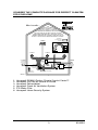
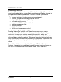
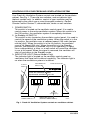
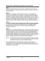
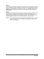
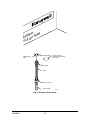
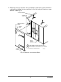
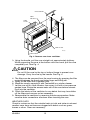
OWNER’S GUIDE
HR230
FRESH AIR
VENTILATION
SYSTEM
69-0854
WELCOME…
…to the world of efficient ventilation. Engineered and built for long,
trouble-free operation, this Honeywell HR230 Fresh Air Ventilation
System provides proper levels of ventilation with energy savings by
transferring heat between the exhaust and fresh air streams. Your home
will now be better protected from indoor pollutants such as formaldehyde, tobacco by-products, radon, moisture, combustion by-products
and carbon monoxide. With the Honeywell Fresh Air Ventilation System,
you can expect to enjoy the benefits of a properly ventilated energy
efficient home for years to come.
Features and benefits:
• Easy-to-clean counterflow core assures years of trouble-free
operation.
• Quiet operation reduces the typical noise levels added by
ventilation products.
• Efficient, low energy consumption saves on utility bills.
• Recovers up to 84% of the difference between indoor and outdoor
temperatures.
CONTENTS
PAGE
THE BENEFITS OF THE PERFECT CLIMATE® SYSTEM
AND THE FRESH AIR VENTILATION SYSTEM .............................. 2
CONSIDER THE COMPLETE PACKAGE FOR PERFECT
CLIMATE® FOR YOUR HOME ........................................................ 3
PERFECT CLIMATE® ........................................................................... 4
CONTROLS FOR YOUR FRESH AIR VENTILATION SYSTEM .......... 5
OPERATING YOUR FRESH AIR VENTILATION SYSTEM .................. 6
GETTING THE MOST FROM YOUR FRESH AIR
VENTILATION SYSTEM ................................................................... 8
MAINTENANCE INSTRUCTIONS FOR THE FRESH AIR
VENTILATION SYSTEM ................................................................... 9
LIMITED WARRANTY ................................................ Inside Back Cover
Attention Homeowner:
The HR230 Fresh Air Ventilation System must be maintained on a
regular basis for maximum efficiency. For complete instructions on
maintaining your Fresh Air Ventilation System, refer to the Maintenance
Instructions for the Fresh Air Ventilation System section on page 9.
1
69-0854
THE BENEFITS OF THE PERFECT CLIMATE® SYSTEM AND THE
FRESH AIR VENTILATION SYSTEM
We take it for granted that our homes protect us from the elements.
But, because of tighter, better quality home constructions, our indoor
environments may be exposing us to unacceptable levels of the very
things we are trying to escape—excessive heat, dryness, humidity,
toxic gases, dust and contaminants—sealed neatly in by the
weatherproofing.
So, what’s the weather forecast for indoors?
Today’s indoor forecast is stormy weather for many homeowners. But
rapid clearing and fresh breezes are just around the corner!
Feeling Right at Home
Unlike what the outdoor brings us, you can have control of indoor
conditions. Temperature, humidity levels and air quality all can affect
physical health, mental attitude, general comfort and energy savings.
With today’s technological advances, you can achieve a “perfect
climate” indoors.
After all, people look to their homes as a place to escape the stresses
of work, a busy lifestyle and an increasingly polluted outdoor environment. Creating a perfect indoor climate is becoming critical to feeling
right at home.
The Honeywell Fresh Air Ventilation System removes stale, unhealthy
inside air and replaces it with a stream of fresh air.
Have you considered the complete package of Perfect Climate controls
for your home?
69-0854
2
CONSIDER THE COMPLETE PACKAGE FOR PERFECT CLIMATE®
FOR YOUR HOME
How it works...
THE
PERFECT CLIMATE
COMFORT CENTER™ IS ONE
PART OF A PERFECT CLIMATE®,
AN INDOOR ENVIRONMENT THAT MAKES
YOU FEEL BETTER, ALLOWS YOU TO LIVE AND
WORK MORE COMFORTABLY, MAINTAINS PRECISE
INDOOR TEMPERATURE, HUMIDITY AND PRECISE AIR
QUALITY, AND ACHIEVES MAXIMUM ENERGY SAVINGS.
HONEYWELL
HOME SECURITY
SYSTEMS
HONEYWELL
PC8900
CONDITIONED
AIR
CONDITIONED
AIR
RETURN AIR
REGISTER
SUPPLY AIR
REGISTER
HONEYWELL
W8900
OPTIMAL
EFFICIENCY AIR
CONDITIONER
OR HEAT PUMP
STALE AIR
EXHAUST
COLD AIR
RETURN
OPTIMAL
EFFICIENCY
FORCED AIR
FURNACE
HONEYWELL
WATER FILTER
STALE
AIR FROM
BATHS
HUMIDIFIER
FRESH AIR
INTAKE
HONEYWELL
FRESH
VENTILATOR
AIR TO
HOME
HONEYWELL
ELECTRONIC AIR CLEANER
M6350
1.
2.
3.
4.
5.
6.
Honeywell PC8900 Perfect Climate Comfort Center™
Honeywell F50, the air cleaner of choice
Honeywell Dehumidistat
Honeywell Fresh Air Ventilation System
F76 Water Filter
Honeywell Home Security System
3
69-0854
PERFECT CLIMATE®
Describing Perfection
The most convenient, most energy efficient, cleanest, healthiest and
most comfortable indoor environment possible today! Perfect climate is
achieved when the components of a home’s climate system work
together:
• optimal efficiency heating and cooling equipment.
• precise, programmable temperature control.
• high efficiency air cleaning/filtering.
• proper humidity control.
• proper ventilation and air distribution.
• whole house water filter.
• security system.
• lighting control.
• multi-zone temperature control.
Products for a Perfect Climate® System
Heating and cooling system: This is the workhorse of your indoor
climate system. Good advice is to have your local heating/cooling
contractor tune up your system annually for comfort, safety and
economy reasons. If your heating plant is old, think about replacing it
with a modern and improved unit. Advances in product technology have
very impressively increased the efficiency of equipment. Sometimes the
improved performance will pay back much of the cost in a few short
years.
For additional information about the Honeywell Perfect Climate®
System, please visit our website at www.honeywell.com/yourhome, or
call the 24-hour automated information line at 1-800-468-1502.
69-0854
4
CONTROLS FOR YOUR FRESH AIR VENTILATION SYSTEM
Your Fresh Air Ventilation System controls are located on the ventilator
cabinet. See Fig. 1. There are two switches, and an indicator light
(defrost models only). In addition, control of your ventilator may be
enhanced by the use of one or more Honeywell products—Perfect
Climate Comfort Centers™, dehumidistats, timers or wall switches.
1. POWER SWITCH
This switch is located on the ventilator control panel. It is used to
control power to the entire ventilation system. When this switch is in
the Off position, the ventilation system is completely shutdown.
2. Lo-Standby-Hi SWITCH
This switch is also located on the ventilator control panel. It is used to
control the speed of the ventilation system. When the switch is in the
Lo position, the ventilator runs at reduced speed (135 cubic feet per
minute [cfm]). When the switch is in the Hi position, the ventilator
runs at full speed (230 cfm). When the switch is in the Standby
position, the ventilator is powered, but it is not operating. A signal
from a dehumidistat, a timer, or a wall switch will cause the ventilator
to run at full speed. When the signal is removed, the ventilator will
shut off and return to the Standby mode.
3. INDICATOR LIGHT (Defrost Models Only)
The indicator light is located on the ventilator control panel on
ventilators that have built-in defrost capability. The indicator light is
on when the ventilation system is in defrost.
LO-STANDBY-HI
SWITCH
SUPPLY
INLET
EXHAUST OUTLET
Fresh Air Ventilation System
Système de ventilation à air frais
Lo
Standby
Hi
Base En attente Haute
Off
POWER
On
A ALIMENATION M
Defrost Cycle
Cycle de dégivrage
POWER SWITCH
INDICATOR LIGHT
(DEFROST MODELS ONLY)
M7612
Fig. 1. Fresh Air Ventilation System controls on ventilator cabinet.
5
69-0854
OPERATING YOUR FRESH AIR VENTILATION SYSTEM
Step 1
Move the power switch to the On position. With this switch in the Off
position, all power to the system is removed and no system controls will
have any effect.
Step 2
Move the Lo-Standby-Hi switch to the Lo position. This setting will
provide a low ventilation rate suitable for continuous operation. When
you do not want continuous ventilation, move the switch to the Standby
position. Activating a Perfect Climate Comfort Center, a timer, a wall
switch or the sensing of high humidity by the dehumidistat will switch the
ventilator into the high speed from either the Lo or Standby position.
Move the switch to the Hi position when you want maximum ventilation.
Step 3
The Perfect Climate Comfort Center may be used to control your ventilation rate. This can be done automatically by using the programmed times
or manually by pressing the Ventilate button on the keypad. See the
Perfect Climate Comfort Center™ User’s Guide (form 69-0891) for
complete instructions.
Step 4
When one or more dehumidistats are part of the control scheme, set the
dehumidistat at the desired humidity level. Generally, the dehumidistat(s)
should be located in areas, such as a bathroom, that generate excess
moisture. When a shower is used, the local humidity level will go above
the dehumidistat setpoint and the ventilation system will switch to the high
speed (maximum ventilation). The ventilation system will return to the
previous setting when the humidity drops below the setpoint.
NOTE: When there is more moisture in the outside air than the inside
air (summer time), turn off the dehumidistat(s). Moisture laden
outdoor air brought inside will not dry the house.
If your heating system has a powered humidifier, make sure the
dehumidistat is set at least ten percent relative humidity above your
humidistat. It may be necessary to lower the humidistat setting to avoid
condensation in the winter.
69-0854
6
Step 5
Your Fresh Air Ventilation System may utilize one or more timers. When
a high ventilation rate is desired, turn the timer to the desired number on
minutes. The Ventilator will switch from the Lo or Standby setting to the
high speed. The ventilator will return to the previous setting when the
time runs out.
Step 6
Your Fresh Air Ventilation System may utilize one or more wall switches
to provide manual control of the system. If a high ventilation rate is
desired, move a switch to the maximum position. The ventilator will run
at high speed until the switch is returned to the normal position.
NOTE: The ventilator will run at high speed if any device in the system
(Perfect Climate Comfort Center, dehumidistat, timer or wall
switch) is activated.
7
69-0854
GETTING THE MOST FROM YOUR FRESH AIR VENTILATION
SYSTEM
Moisture Control
Continual operation of the ventilation system is recommended for
optimum reduction of indoor air pollution and control of humidity.
Increased moisture removal will always occur at maximum ventilation
rates. Use the Hi switch position when first occupying a newly built
home to remove excess moisture from new wood, plaster, cement and
other moisture absorbing construction materials. If your system is wired
to a dehumidistat, it will switch the ventilator to the high speed setting
whenever the humidity level goes above the setpoint.
NOTE: When the amount of moisture in the outside air is greater than
the amount in the inside air, running the ventilation system will
not dry the home. This will occur most often in the summer
months.
Remote Override Switch Functions
Your Fresh Air Ventilation System may incorporate one or more
remotely mounted Perfect Climate Comfort Centers™, dehumidistats,
timers or wall switches. When any of these devices are activated, the
ventilator will run at the high speed. The ventilator will return to the
previous setting when all the remote devices are deactivated. The
remote override function, in combination with the Standby setting, is
especially useful for intermittent bathroom exhaust where continuous
ventilation is not required. Continuous operation is recommended
except when the home is unoccupied, or when proper ventilation is
provided by other means such as open doors and windows.
Defrost
Ventilators designed for use in cold climates are equipped with an
automatic defrost system. The ventilator automatically detects restricted
airflow in the heat transfer core when ice starts to form and a defrost
cycle is initiated. The ventilator is closed off from the duct system, an
auxiliary heater is turned on and the air inside the ventilator is recirculated continually to melt the ice that has formed. When the airflow
returns to normal, the sequence is reversed and ventilation returns to
normal. When the ventilator is in defrost, the LED indicator light on the
control panel is illuminated. Defrost time is held to a minimum by
Honeywell’s exclusive automatic defrost initiation circuit.
69-0854
8
MAINTENANCE INSTRUCTIONS FOR THE FRESH AIR VENTILATION
SYSTEM
CAUTION
Electric shock hazard.
Can cause personal injury or equipment damage.
Before doing maintenance, disconnect power to the ventilator by
unplugging the power cord.
NOTE: Your Fresh Air Ventilation System must be maintained on a
regular basis for the best efficiency. Honeywell recommends
the Fresh Air Ventilation System be cleaned and checked at
least twice a year, preferably at the start of each heating and
cooling season.
Check and/or Clean as Follows:
HEAT TRANSFER CORE AND FILTERS
The room air filter, fresh air filter and the heat transfer core are removed
from the ventilator as a unit.
1. Remove the drain hose(s) from the bottom of the check valve. Turn
the check valve and fitting out of the bottom of the ventilator. Use a
wrench or pliers to loosen the fitting, if necessary. See Fig. 2.
9
69-0854
m s
ste ir frai
y
S a
à
on
DRAIN ACCESS
HOLES ON BOTTOM
OF HR230
CORE DRAIN
HOLE
FITTING
HOSE
CHECK VALVE
DRAIN HOSE
M7610
Fig. 2. Remove drain hose.
69-0854
10
2. Remove the core access door (located on the back of the ventilator
cabinet) by sliding the two catches to the left and pull the door open
and off. See Fig. 3.
HR230 CABINET
DOOR TAB
SLOT
CORE ACCESS
DOOR
2
DOOR
TAB
2
1
DOOR
LATCH
BRACKET
1
1 SLIDE DOOR LATCHES TO THE LEFT.
2 WHEN DOOR IS RELEASED, PULL DOOR
TABS OUT FROM SLOTS.
DOOR
LATCH
M7604
Fig. 3. Remove core access door.
11
69-0854
HR230 CABINET
CORE
HOUSING
CORE
FILTER
CORE FILTER
M7605
CORE HANDLE
Fig. 4. Remove core from ventilator.
3. Using the handle, pull the core straight out approximately halfway.
While supporting the core at the bottom with one hand, pull the core
completely out. See Fig. 4.
CAUTION
Do not lift the core by the top or bottom flange to prevent core
damage. Carry the core by the handle. See Fig. 4.
4. The filters can be removed from the core housing by grasping the filter
material between the thumb and index finger and lifting out.
5. Spray off the filters with a garden hose.
6. Wash the core by spraying it with Fantastik® or a similar cleaner.
7. Let the core sit for a few minutes, then spray it off with a low pressure
garden hose. Shake the excess water out of the core before reinserting it into the ventilator.
8. Check the interior of the ventilator for any debris that may have fallen
off the filters and vacuum out as necessary.
9. Reassemble the ventilator by reversing the above procedure. Make
sure the drain connections are down when inserting the core.
WEATHER CAPS
Check to make sure that the outside fresh air inlet and stale air exhaust
weather caps have not become clogged with debris such as grass,
leaves or snow. Clean as necessary.
69-0854
12
LIMITED WARRANTY
Honeywell warrants this product to be free from defects in the workmanship or materials, under normal use and service, for a period of one (1)
year from the date or purchase by the consumer. If, at any time during
the warranty period, the product is defective or malfunctions, Honeywell
shall repair or replace it (at Honeywell’s option) within a reasonable
period of time.
If the product is defective, please contact:
a) the dealer from whom you purchased it, or
b) the local Honeywell Home and Building Control Sales Office who
will assist you in locating a qualified service representative,
This warranty does not cover removal or reinstallation costs. This
warranty shall not apply if it is shown by Honeywell that the defect or
malfunction was caused by damage which occurred while the product
was in the possession of a consumer.
Honeywell’s sole responsibility shall be repair or replace the product
within the terms stated above. HONEYWELL SHALL NOT BE LIABLE
FOR ANY LOSS OR DAMAGE OF ANY KIND, INCLUDING ANY
INCIDENTAL OR CONSEQUENTIAL DAMAGES RESULTING,
DIRECTLY OR INDIRECTLY, FROM ANY BREACH OF ANY WARRANTY, EXPRESSED OR IMPLIED, OR ANY OTHER FAILURE OF
THIS PRODUCT. Some states do not allow the exclusion or limitation of
incidental or consequential damages, so this limitation may not apply to
you.
THE WARRANTIES SET FORTH HEREIN ARE EXCLUSIVE, AND
HONEYWELL EXPRESSLY DISCLAIMS ALL OTHER WARRANTIES,
WHETHER WRITTEN, ORAL, IMPLIED OR STATUTORY, INCLUDING
BUT NOT LIMITED TO ANY WARRANTIES OF MERCHANTABILITY,
WORKMANSHIP, OR FITNESS FOR A PARTICULAR PURPOSE.
This warranty gives you specific legal rights, and you may have other
rights which vary from state to state.
If you have any questions concerning this warranty, please write
to Home and Building Control Customer Relations, Honeywell, 1985
Douglas Drive North, Minneapolis, Minnesota, 55422.
In Canada, Honeywell Limited/ Honeywell Limitée, 35 Dynamic Drive,
Scarborough, Ontario M1V 4Z9.
Contact Your Local Installer
Home and Building Control
Honeywell Inc.
1985 Douglas Drive North
Golden Valley, MN 55422
Home and Building Control
Honeywell Limited-Honeywell Limitée
740 Ellesmere Road
Scarborough, Ontario
M1P 2V9
Helping You Control Your World
C.H. • 6-95 • Printed in U.S.A. • Form Number 69-0854
www.honeywell.com/
yourhome