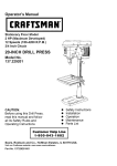
1
English
Model
Modèle
Modelo
Stationary Table Saw
Scie sur table
Sierra de mesa fija
C 10LA
INSTRUCTION MANUAL AND SAFETY INSTRUCTIONS
WARNING
Improper and unsafe use of this power tool can result in death or serious bodily injury!
This manual contains important information about product safety. Please read and understand this manual
before operating the power tool. Please keep this manual available for others before they use the power
tool.
MODE D’EMPLOI ET INSTRUCTIONS DE SECURITE
AVERTISSEMENT
Une utilisation incorrecte et dangereuse de cet outil motorisé peut entraîner la mort ou de
sérieuses blessures corporelles!
Ce mode d’emploi contient d’importantes informations à propos de la sécurité de ce produit.
Priére de lire et d’assimiler ce mode d’emploi avant d’utiliser I’outil motorisé. Garder ce mode
d’emploi à la disponiblilité des autres utilisateurs avant qu’ils utilisent I’outil motorisé.
MANUAL DE INSTRUCCIONES E INSTRUCCIONES DE SEGURIDAD
ADVERTENCIA
!
La utilización inapropiada e insegura de esta herramienta el
eléctrica puede resultar en lesiones
serias o en la muerte!
Este manual contiene información importante sobre la seguridad del producto. Lea y comprenda
este manual antes de utilizar la herramienta eléctrica. Guarde este manual para que puedan
leerlo otras personas antes de que utilicen la herramienta eléctrica.
Hitachi Koki
English
English
CONTENTS
SECTION
PAGE
Product Specifications ........................................
3
Power Tool Safety ..............................................
4
Table Saw Safety ................................................
5
Electrical Requirements and Safety ....................
6
Accessories and Attachments ............................
7
Tools Needed for Assembly ................................
7
Carton Contents ..................................................
7
SECTION
PAGE
Know Your Table Saw ........................................
9
Glossary of Terms ...............................................
10
Assembly and Adjustments .................................
11
Operation ............................................................
18
Maintenance .......................................................
23
Troubleshooting Guide ........................................
24
Push Stick Pattern ...............................................
25
Parts List .............................................................
72
HITACHI AUTHORIZED SERVICE CENTERS
Service under this warranty is available from Hitachi Koki U.S.A., Ltd. at:
IN THE U.S.A.
IN CANADA
3950 Steve Reynolds Blvd. Norcross, GA 30093
9409 Owensmouth Ave. Chatsworth, CA 91311
OR CALL: (800) 546-1666 for a service center nearest you.
Français
6395 Kestrel Road Mississauga, ON L5T 1Z5
OR CALL: (800) 970-2299 for a service center nearest you.
TABLE DES MATIERES
SECTION
PAGE SECTION
PAGE
Spécifications produit ......................................................... 26
Connaître votre scie sur table ..................
32
Consignes de sécurité relatives aux outile électriques ....... 27
Glossaire des termes ...............................
33
Consignes de sécurité relatives à la scie sur table ................ 28
Montage et réglages ................................
34
Exigences électriques et sécurité ....................................... 29
Utilisation .................................................
41
Accessoires ........................................................................ 30
Entretien ...................................................
46
Outils nécessaires pour le montage ................................... 30
Guide de dépannage ................................
47
Contenu de l’emballage ...................................................... 30
Plan du poussoir ......................................
48
Liste des piéces .......................................
72
CENTRES TECHNIQUES HITACHI AGREES
La réparation est réalisée dans le cadre de cette garantie par Hitachi Koki U.S.A., Ltd. :
AU CANADA
AUX ETATS-UNIS
6395 Kestrel Road Mississauga, ON L5T 1Z5
3950 Steve Reynolds Blvd. Norcross, GA 30093
9409 Owensmouth Ave. Chatsworth, CA 91311
OU APPELEZ LE: (800) 546-1666 pour connaître le center
technique le plus proche de chez vous.
Español
OU APPELEZ LE: (800) 970-2299 pour connaître le center
technique le plus proche de chez vous.
ÍNDICE
SECCIÓN
PÁGINA SECCIÓN
PÁGINA
Especificaciones del producto ..........................
49
Conozca su sierra de mesa ................................
55
Seguridad de la herramienta eléctrica ..............
50
Glosario de Términos..........................................
56
Seguridad de la sierra de mesa ........................
51
Montaje y ajustes ................................................
57
Requisitos eléctricos y seguridad .....................
52
Funcionamiento ..................................................
64
Accesorios ........................................................
53
Mantenimiento ....................................................
69
Herramientas necesarias para el montaje ........
53
Guía de solución de problemas ..........................
70
Contenido de la caja .........................................
53
Patrón de empujadores ......................................
71
Lista de piezas ....................................................
72
CENTROS DE SERVICIO AUTORIZADOS DE HITACHI
Hitachi Koki U.S.A. Ltd. proporciona un servicio de reparaciones bajo esta garantía en:
EN EE. UU.
EN CANADA
3950 Steve Reynolds Blvd. Norcross, GA 30093
9409 Owensmouth Ave. Chatsworth, CA 91311
O LLAME AL: (800) 546-1666 para informarse del centro de
reparaciones más cercano.
– 2 –
6395 Kestrel Road Mississauga, ON L5T 1Z5
O LLAME AL: (800) 970-2299 para informarse del centro de
reparaciones más cercano.
English
WARNING
Some dust created by power sanding, sawing, grinding, drilling and other construction activities contains
chemicals known to the state of California to cause cancer, birth defects or other reproductive harm. Some
examples of these chemicals are:
• Lead based paints
• Crystalline silica from bricks, cement and other masonry products
• Arsenic and chromium from chemically treated lumber
Your risk from these exposures varies, depending on how often you do this type of work. To reduce your
exposure to these chemicals, work in a well-ventilated area and work with approved safety equipment, such
as dust masks that are specially designed to filter out microscopic particles.
PRODUCT SPECIFICATIONS
MOTOR
HP (Maximum developed) ...................
Type .....................................................
Amps ....................................................
Voltage .................................................
Hz .........................................................
RPM (no load) ......................................
Overload Protection .............................
3.5
Induction
15/7.5
120/240
60
3450
YES
SAW
Table Size with Extension........................ 27-1/8” x 40-1/8”
Table Extension ...................................... Right & Left
Extension Fence Capacity (Maximum).... Right 30”, Left 18”
Blade Size................................................ 10”
Rip Scale ................................................. YES
Rip Fence ................................................ YES
Miter Gauge ............................................ YES
Maximum Cut Depth @ 90º .................... 3-3/8”
Maximum Cut Depth @ 45º .................... 2-1/4”
Maximum Dado Cut Width ...................... 13/16”
Net Weight .............................................. 299.8 LBS
WARNING
To avoid electrical hazards, fire hazards or damage to the table saw, use proper circuit protection.
This table saw is wired at the factory for 110-120/220-240 Volt operation. It must be connected to a 110-120
Volt / 15 Ampere or 220-240 Volt / 7.5 Ampere time delay fuse or circuit breaker. To avoid shock or fire, replace
power cord immediately if it is worn, cut or damaged in any way.
Before using your table saw, it is critical that you read and understand these safety rules. Failure to follow
these rules could result in serious injury to you or damage to the table saw.
– 3 –
English
POWER TOOL SAFETY
WARNING
Before using your table saw, it is critical that you read and understand these safety rules. Failure to follow
these rules could result in serious injury or damage to the table saw.
Good safety practices are a combination of common
sense, staying alert and understanding how to use your
power tool. To avoid mistakes that could cause serious
injury, do not plug in your power tool until you have read
and understood the following safety rules:
accessories. The use of improper accessories may
cause injury to you or damage to the tool.
15. REMOVE ADJUSTING KEYS AND WRENCHES.
Form the habit of checking to see that keys and
adjusting wrenches are removed from the tool
before turning ON.
16. NEVER LEAVE TOOL RUNNING UNATTENDED.
TURN THE POWER OFF. Do not leave the tool
before the blade comes to a complete stop.
1. READ and become familiar with this entire
Operator’s Manual. LEARN the tool’s applications,
limitations and possible hazards.
2.
WARNING
Look for this symbol that identifies important
safety precautions. It means BE ALERT! YOUR
SAFETY IS INVOLVED!
17. NEVER STAND ON TOOL. Serious injury could
occur if the tool is tipped or if the cutting tool is
unintentionally contacted.
3. NEVER OPERATE THIS MACHINE WITHOUT
THE SAFETY GUARD IN PLACE FOR ALL
THROUGH–SAWING OPERATIONS.
18. DO NOT OVERREACH. Keep proper footing and
balance at all times.
4. DO NOT USE IN A DANGEROUS ENVIRONMENT
such as damp or wet locations or in the rain. Keep
work area well lighted.
19. MAINTAIN TOOLS WITH CARE. Keep tools sharp
and clean for most efficient and safest performance.
Follow instructions for lubricating and changing
accessories.
5. DO NOT use power tools in the presence of
flammable liquids or gases.
6. KEEP WORK AREA CLEAN. Cluttered areas and
benches invite accidents.
7. KEEP CHILDREN AWAY. All visitors should be kept
at a safe distance from the work area.
8. DO NOT FORCE THE TOOL. It will do the job
better and safer if used at the rate for which it was
designed.
20. CHECK FOR DAMAGED OR LOOSE PARTS.
Check for alignment of moving parts, binding
of moving parts, loose mounting and any other
conditions that may affect its safe operation. A
guard or other part that is loose or damaged should
be properly adjusted, repaired or replaced.
21. MAKE WORKSHOP CHILDPROOF with padlocks,
master switches or by removing starter keys.
22. DO NOT operate the tool if you are under the
influence of any drugs, alcohol or medication that
could impair your ability to use the tool safely.
9. USE THE RIGHT TOOL. Don’t force the tool or
attachment to do a job for which it is not designed.
23. USE A DUST COLLECTION SYSTEM whenever
possible. Dust generated from certain materials can
be hazardous to your health and, in some cases,
a fire hazard. Always operate the power tool in a
well-ventilated area with adequate dust removal.
10. WEAR PROPER APPAREL. DO NOT wear loose
clothing, gloves, neckties, rings, bracelets or other
jewelry that may get caught in moving parts.
Non-slip footwear is recommended. Wear protective
hair covering to contain long hair.
24. ALWAYS WEAR EYE PROTECTION. Any power
tool can throw debris into your eyes that could
cause permanent eye damage. ALWAYS wear
safety goggles (not glasses) that comply with ANSI
safety standard Z87.1. Everyday glasses have only
impact resistant lenses. They ARE NOT safety
glasses.
NOTE: Glasses or goggles not in compliance with
ANSI Z87.1 could cause serious injury when they
break.
11. WEAR A FACE MASK OR DUST MASK. Sawing,
cutting and sanding operations produce dust.
12. DISCONNECT TOOLS before servicing and when
changing accessories, such as blades, cutters, etc.
13. REDUCE THE RISK OF UNINTENTIONAL
STARTING. Make sure the switch is in the OFF
position before plugging tool into the power supply.
14. USE ONLY RECOMMENDED ACCESSORIES.
Consult the Operator’s Manual for recommended
– 4 –
25. DIRECTION OF FEED. Feed work into a blade or
cutter against the direction of rotation of the blade or
cutter only.
English
TABLE SAW SAFETY
12. PROVIDE ADEQUATE SUPPORT to the rear
and the sides of the saw table for long or wide
workpieces.
1. ALWAYS USE SAW BLADE GUARD, splitter
and antikickback pawls for every operation for
which they can be used, including through sawing.
Through sawing operations are those in which the
blade cuts completely through the workpiece when
ripping or crosscutting.
2. ALWAYS HOLD WORK FIRMLY against the miter
gauge or rip fence.
3. ALWAYS USE a push stick, especially when ripping
narrow stock. Refer to ripping instructions in this
Operator’s Manual where the push stick is covered
in detail. A pattern for making your own push stick is
included on page 25.
4. NEVER PERFORM ANY OPERATION
FREEHAND, which means using only your hands
to support or guide the workpiece. Always use
either the fence or the miter gauge to position
and guide the work.
WARNING: FREEHAND CUTTING IS THE
MAJOR CAUSE OF KICKBACK AND FINGER/
HAND AMPUTATIONS.
5. NEVER STAND or have any part of your body in
line with the path of the saw blade. Keep your hands
out of the saw blade path.
13. AVOID KICKBACKS (work thrown back towards
you) by keeping the blade sharp, the rip fence
parallel to the saw blade and by keeping the splitter,
anti-kickback pawls and guards in place, aligned
and functioning. Do not release work before passing
it completely beyond the saw blade. Do not rip work
that is twisted, warped or does not have a straight
edge to guide it along the fence.
14. AVOID AWKWARD OPERATIONS and hand
positions where a sudden slip could cause your
hand to move into the saw blade.
15. NEVER USE SOLVENTS to clean plastic parts.
Solvents could possibly dissolve or otherwise
damage the material. Only a soft damp cloth should
be used to clean plastic parts.
16. MOUNT your table saw on a bench or stand
before performing any cutting operations. Refer to
ASSEMBLY AND ADJUSTMENTS on page 11.
17. NEVER CUT METALS or materials that may make
hazardous dust.
18. ALWAYS USE IN A WELL-VENTILATED AREA.
Remove sawdust frequently. Clean out sawdust
from the interior of the saw to prevent a potential
fire hazard. Attach a vacuum to the dust port for
additional sawdust removal.
6. NEVER REACH behind or over the cutting tool for
any reason.
7. REMOVE the rip fence when crosscutting.
8. DO NOT USE a molding head with this saw.
19. NEVER LEAVE THE SAW RUNNING
UNATTENDED. Do not leave the saw until the blade
comes to a complete stop.
9. FEED WORK INTO THE BLADE against the
direction of rotation only.
20. For proper operation follow the instructions in
this Operator’s Manual entitled ASSEMBLY AND
ADJUSTMENTS (Page 11). Failure to provide
sawdust fall-through and removal hole will allow
sawdust to build up in the motor area resulting in a
fire hazard and potential motor damage.
10. NEVER use the rip fence as a cut-off gauge when
crosscutting.
11. NEVER ATTEMPT TO FREE A STALLED SAW
BLADE without first turning the saw OFF. Turn
power switch OFF immediately to prevent motor
damage.
– 5 –
English
ELECTRICAL REQUIREMENTS AND SAFETY
DO NOT MODIFY THE PLUG PROVIDED. If it will not
fit the receptacle, have the proper receptacle installed
by a qualified electrician.
POWER SUPPLY REQUIREMENTS
WARNING
IMPROPER CONNECTION of the equipment grounding
conductor can result in risk of electric shock. The
conductor (wire) with the green insulation (with or
without yellow stripes) is the equipment grounding
conductor. If repair or replacement of the electric cord
or plug is necessary, DO NOT connect the equipment
grounding conductor to a live terminal.
To avoid electrical hazards, fire hazards or damage
to the table saw, use proper circuit protection.
Always use a separate electrical circuit for your
tools. This power tool is wired at the factory for
120V operation. Connect it to a 120V, 15 Amp circuit
and use a 15 Amp time delay fuse or circuit breaker.
To avoid shock or fire, replace the cord immediately
if it is worn, cut or damaged in any way.
CHECK with a qualified electrician or service personnel
if you do not completely understand the grounding
instructions, or if you are not sure the saw is properly
grounded.
EXTENSION CORD REQUIREMENTS
WARNING
Use only 3-wire extension cords that have 3-prong
grounding plugs and 3-pole grounding receptacles that
accept the saw’s plug. Repair or replace damaged or
worn cords immediately.
Any extension cord must be GROUNDED for safe
operation.
MINIMUM GAUGE FOR EXTENSION CORDS (AWG)
Ampere Rating
Volts
Total length of Cord
More Than Not More Than 120V 25ft. 50ft.
100ft. 150ft.
240V 50ft. 100ft. 200ft. 300ft.
0
6
18
16
16
14
6
10
18
16
14
12
10
12
16
16
14
12
12
16
14
12
Not Recommended
3-Prong
-Prong Plug
Grounding Prong
Properly Grounded
3-Prong Receptacle
GUIDELINES FOR EXTENSION CORDS
Any extension cord used for power tools MUST be
grounded (3-wire with two flat prongs and one round
ground prong).
Grounding Lug
Make sure this is
connected to a
connect
known ground.
g
Make sure the extension cord is in good condition.
When using an extension cord, make sure you use one
heavy enough to carry the current the tool will draw.
An undersized cord will cause a drop in line voltage
resulting in loss of power and overheating. The table
above shows the correct size to use according to
extension cord length and nameplate ampere rating. If
in doubt, use the next heavier gauge cord. The smaller
the gauge number the heavier the cord.
NOTE: The 12 to 16 amp rating is correct for this tool. It
is highlighted in the table above.
Adapter
240V OPERATION
The table saw provided a dual voltage, 120V and 240V,
motor. To operate the table saw at 240V, single phase,
reconnect the motor wire as the wire wirding on page
74.
Be sure your extension cord is properly wired and in
good condition. Always replace a damaged extension
cord or have it repaired by a qualified person before
using it. Protect your extension cords from sharp
objects, excessive heat and damp or wet areas.
Before connecting the saw to the extension cord, make
sure the saw switch is turned OFF.
WARNING
To avoid injury, disconnect the motor from power source
outlet before reconnecting the wire.
To operate the table saw at 240V, replace the 120V
plug with a UL/CSA listed plug suitable for 240V (not
included) and the rated current of the saw as shown.
Contact your local Hitachi Authorized Service Center or
qualified electrician for proper procedures to install the
plug. The saw must comply with all local and national
electrical codes after the 240V plug is installed. Connect
the table saw with 240V plug to a power source outlet
as shown.
GROUNDING INSTRUCTIONS
IN THE EVENT OF A MALFUNCTION OR
BREAKDOWN, grounding provides a path of least
resistance for electric current and reduces the risk of
electric shock. This saw is equipped with an electric
cord that has an equipment grounding conductor and
a grounding plug. The plug MUST be plugged into
a matching receptacle that is properly installed and
grounded in accordance with ALL local codes and
ordinances.
2-Prong
-Prong
Receptacle
– 6 –
English
ACCESSORIES AND ATTACHMENTS
RECOMMENDED ACCESSORIES
WARNING
WARNING
Visit your Hardware Department or see the Power
and Hand Tools Catalog to purchase recommended
accessories for this power tool.
To avoid the risk of personal injury:
• Do not use a dado with a diameter larger than 8”.
• Maximum dado width is 13/16”. DO NOT USE
WIDER COMBINATIONS.
• Do not use molding head set with this saw.
• Do not modify this power tool or use accessories
not recommended by Store.
TOOLS NEEDED FOR ASSEMBLY
Supplied
Hex Wrench
Not Supplied
Medium Screwdriver
Adjustable Wrench
#2 Phillips screwdriver
Combination Square
Straight Edge
CARTON CONTENTS
UNPACKING AND CHECKING CONTENTS
N
O
P
Q
R
Separate all parts from packing materials. Check each
part with the illustration on the next page and the “Table
of Loose Parts” to make certain all items are accounted
for, before discarding any packing material.
1 set
1 each
1
1
2
WARNING
If any part is missing or damaged, do not attempt
to assemble the table saw, plug in the power cord,
or turn the switch ON until the missing or damaged
part is obtained and is installed correctly.
TABLE OF LOOSE PARTS
ITEM
A
B
C
D
E
F
G
H
I
J
K
L
M
Table extension hardware
Blade guard and splitter
Dado table insert
Rear table extension
Support rod
DESCRIPTION
QUANTITY
Table saw assembly
1
Rail cover
6
Rip fence
1
Table extension wing
2
Front table extension rail
2
Rear table extension rail
2
Blade
1
Blade wrench
1
Handwheel and handle
1
Adhesive washer
5
Miter gauge
1
Storage bracket & foot hardware
1 set
Handwheel handle & nuts
1 each
NOTE: To make assembly easier, keep contents of box
together. Apply a coat of automobile wax to the table.
Wipe all parts thoroughly with a clean dry cloth. This will
reduce friction when pushing the workpiece.
– 7 –
English
UNPACKING YOUR STATIONARY TABLE SAW
Q
R
A
D
B
C
H
I
G
E
J
F
K
P
L
M
O
N
– 8 –
English
KNOW YOUR STATIONARY TABLE SAW
Blade tilt scale
Table extension (Left)
Miter gauge
Blade guard
Table Insert
Rip fence
Table extension (Right)
Table
Blade elevation handwheel
Blade tilting handwheel
ON/OFF switch with key
Miter gauge storage
Rear table extension
Rip fence storage
– 9 –
English
GLOSSARY OF TERMS
HITACHI PROFESSIONAL
TABLE SAW TERMS
CROSSCUT – A cut made across the width of the
workpiece.
MITER GAUGE – A guide used for crosscutting
operations that slides in the tabletop channels located
on either side of the blade. It helps make accurate
straight or angle cuts.
FREEHAND – Performing a cut without using a fence
(guide), hold down or other proper device to prevent the
workpiece from twisting during the cutting operation.
GUM – A sticky sap from wood products.
RIP FENCE – A guide used for rip cutting that clamps to
the tabletop. It allows the workpiece to be straight.
HEEL – Misalignment of the blade.
TABLE INSERT – Provides access to the blade arbor
for changing blades.
KERF – The amount of material removed by a blade
cut.
OVERLOAD RESET SWITCH – Resets the
thermocouple and provides a way to restart the saw
motor if it overheats or overloads.
MITER CUT – An angle cut made across the width of
the workpiece.
RESIN – A sticky sap that has hardened.
BLADE BEVEL SCALE – Measures the angle the blade
is tilted when set for a bevel cut.
TABLE SCALE – Measures the distance the rip fence is
set from the blade, allowing quick setups.
ANTI-KICKBACK PAWLS – Prevents the workpiece
from being kicked upward or back toward the front of the
table saw by the spinning blade.
SPLITTER – Keeps the workpiece spread apart
after being cut, to prevent binding on the blade and
workpiece.
BLADE ELEVATION HANDWHEEL – Raises and
lowers the blade.
REVOLUTIONS PER MINUTE (RPM) – The number of
turns completed by a spinning object in one minute.
SAW BLADE PATH – The area of the workpiece or
table top directly in line with the travel of the blade or the
part of the workpiece that will be cut.
SET – The distance between two saw blade tips, bent
outward in opposite directions to each other. The further
apart the tips are, the greater the set.
WORKPIECE – The item being cut. The surfaces of a
workpiece are commonly referred to as faces, ends and
edges.
BLADE TILTING HANDWHEEL – Tilts the blade to any
angle between 0° to 45° for bevel cuts.
Leading Edge
Saw Blade Path
Kerf
WOODWORKING TERMS
Surface
ARBOR – The shaft on which a blade is mounted.
Trailing Edge
BEVEL CUT – An angle cut made through the face of
the workpiece.
Workpiece
COMPOUND CUT – A simultaneous bevel and miter
cut.
– 10 –
English
ASSEMBLY AND ADJUSTMENTS
4. Adjust the mounting bolts (2) until the extension is
flush with the saw table. Tighten.
5. Repeat these procedures for the right extension
table.
REMOVE THE STYROFOAM FROM THE CABINETSTAND (FIG. A & A-1)
WARNING
Fig. B
To avoid injury from an accidental start, make sure
the STYROFOAM is removed from the cabinet stand.
1. Remove the back cover (2) of the base by removing
the screws (1), three for each side.
2. Turn the blade elevation handwheel in front of the
table saw to raise the motor (3).
3. Remove the styrofoam (4) under the motor.
4. Replace the back cover (2) and then tighten the
screws (1), three for each side.
Fig. A
1
2
Fig. A-1
3
4
1
2
ASSEMBLY THE FRONT AND REAR TABLE RAIL
(FIG. B-1, B-2)
NOTE: Front of table rails assemblies are different.
Assembly the front rail (Fig. B-1)
1. Attach the right front side cover (1) into right front
table rail (2). Repeat for the left front rail.
2. Place the hex. bolts M8-20 (3), hex bolts M8-16 (4)
through the holes at the front table edge. Screw the
square nuts (5) onto each bolts.
NOTE: Keep the bolts and square nuts loosened
before front rail fixed.
3. Attach the right front rail onto proper location by
having the square nuts pass through the slot of the
front rail. Repeat for the left front rail.
4. Attach the middle plug (6) to connect the two half
front rail.
5. When the blade was installed, use the rip fence and
gauge to adjust the front rail to proper location. When
the front rail is level with table, then fix the front rail
by tightening the six bolts.
Fig. B-1
ASSEMBLY THE TABLE EXTENSION (FIG. B)
WARNING
5
4
3
To avoid injury, beware the weight of the table
extension before assembling the table extension.
4
1. Place the left table extension next to the saw table,
aligning the mounting holes (1).
2. Place bolts (2) and thread in mounting holes.
3. Place a straight edge or combination square on the
saw table, across the table extension.
6
2
– 11 –
1
English
Assembly the rear table rail (Fig. B-2)
6. Attach the middle plug (1) to the rear table rails (2).
7. Place the rear table rails on the saw table, aligning
with the holes in each rail.
8. Place the bolts (3) and tread in the holes; tighten the
bolts and check the alignment again.
Fig. B-2
BLADE RAISING HANDWHEEL (FIG. D)
Thread the blade handwheel handle (1) into blade
raising handwheel (2) and tighten.
BLADE TILTING HANDWHEEL (FIG. D)
1. Attach the blade tilting handwheel (3) to the elevation
screw at the front of the saw.
2. Attach and tighten the dome nut (4) at the end of the
shaft.
3
2
Fig. D
1
2
1
ASSEMBLY THE REAR TABLE EXTENSION
(FIG. C)
NOTE: The maximum load for the rear table
extension is 30 kg.
1. Insert the support rods (1) into the slot on the body
shell. Place screws (2) and tighten.
2. Attach the rear table extension (3) to the support
rods (1). Place screws (4) and tighten.
3. Place the screws (9) to the slot of the rear table reails
(8).
4. Attach the side cover (10) to the rear table reails (8).
5. Tighten the nuts (7).
6. Align the triangle (5) on the rear table extension and
the middle plug (6).
7. Loosen the nuts (7) and screws (4) to adjust the rear
table extension (3) for alignment.
Fig. C
4
9
8
6
5
3
1
7
2
10
3
4
BLADE GUARD ASSEMBLY (FIG. E, F)
WARNING
To avoid injury from an accidental start, make sure
the switch is in the OFF position and the plug is
disconnected from the power source outlet.
• When installing the blade guard, cover the blade
teeth with a piece of folded cardboard to protect
yourself from possible injury.
• Never operate this machine without the safety
guard in place for all through sawing operations.
Installing the blade guard assembly (Fig. E)
1. Remove the table insert.
2. Unlock the blade bevel lock knob (1).
3 With the blade elevation handwheel (2), raise the
blade to the maximum height.
4. Using the blade tilting handwheel, tilt the blade to 45o
on the bevel scale.
5. Lock the blade tilt locking knob.
6. Locate the splitter assembly mounting bracket in
back of the blade.
7. Cover the blade teeth with a folded cardboard or
position the plastic blade guard over the blade to
protect your hands.
8. Place the two kickback pawls (4) toward the rear of
the table, and align the splitter mounting holes to the
holes in the bracket.
9. Place the steel flat washers (6) on the two bolts (5)
and tread the bolts into the holes.
NOTE: Make sure the “anti-kick back pawls” do not get
caught between the insert and the guard, but rest on top
of the insert.
– 12 –
English
IMPORTANT: The splitter must always be correctly
aligned with the blade so the cut workpiece will pass on
either side without binding or twisting.
Fig. E
6
5
4
2
1
Removing the blade guard assembly (Fig. E)
WARNING
To avoid injury from an accidental start, make sure
the switch is in the OFF position and the plug is
disconnected from the power source outlet.
1. Remove the table insert.
2. With the blade elevation handwheel (2), raise the
blade to the maximum height.
3. Loosen blade lock knob (1) and move the handwheel
(2) to 45° on the bevel scale.
4. Tighten the bevel lock knob (1).
5. Cover the blade teeth with a piece of folded
cardboard or position the plastic blade guard over the
blade to protect your hands.
6. Loosen the bolts (5) and remove the blade guard
assembly, then retighten the knob.
7. Return the blade to 90° and replace the table insert.
NOTE: Make sure the “anti-kick back pawls” do not get
caught between the insert and the guard, but rest on top
of the insert.
1. Remove the table insert and raise the blade to the
maximum height by turning the blade elevation
handwheel clockwise.
2. Lift the blade guard and position it toward the rear of
the table.
3. Adjust the blade to the 90O vertical position by
unlocking the blade tilting lock knob and turning the
bevel tilting handwheel counterclockwise, and then
lock into position.
4. To see if the blade (1) and splitter (2) are correctly
aligned, lay a combination square along the side of
the blade and against the splitter (making sure the
square is between the teeth of the blade).
5. Tilt the blade to the 45O position and check the
alignment again.
6 If the blade and splitter are not correctly aligned:
a. Remove the blade guard by removing the wing
bolt that locks the guard in place.
b. Loosen and remove the two bolts (3) from the
mounting bracket (7).
7. Place two adhesive washers (5) on the guard
mounting bracket (attached to the saw). Position
them over the corresponding mounting bolt holes
(refer to step 6-b) after removing the adhesive
backing affixed to the washers.
8. Replace the two guard mounting bolts (3) and tighten
securely. Also reattach the blade guard assembly,
affixing it to the machine by its corresponding wing
bolt.
9. Check the splitter and blade alignment again at both
90O and 45O .
10.Add or remove the adhesive washers until the
alignment is correct.
11.Replace the table insert.
Fig. F
7
5
2
ALIGNING THE BLADE GUARD SPLITTER (FIG. F)
WARNING
2
To avoid injury from an accidental start, make sure
the switch is in the OFF position and the plug is
disconnected from the power source outlet.
• When installing the blade guard, cover the blade teeth
with a piece of folded cardboard to protect yourself
from possible injury.
• Never operate this machine without the safety guard
in place for all through sawing operations.
– 13 –
1
3
English
INSTALLING A BLADE (FIG. G)
REMOVING THE BLADE (FIG. G)
WARNING
WARNING
To avoid injury from an accidental start, make sure
the switch is in the OFF position and the plug is
disconnected from the power source outlet.
To avoid injury from an accidental start, make sure
the switch is in the OFF position and the plug is
disconnected from the power source outlet.
1. Remove the table insert and raise the blade to the
maximum height by turning the blade elevation
handwheel clockwise.
2. Lift the blade guard and position it toward the rear of
the table.
3. Adjust the blade to the 90° vertical position by
unlocking the blade tilting lock knob and turning the
bevel tilting handwheel counterclockwise, and then
lock into position.
4. Pull the motor locking lever (1) toward the front of the
machine while spinning the blade until the latch locks
into place and the blade will no longer turn.
5. Place the blade wrench (3) on the arbor nut (4).
6. Loosen and remove the arbor nut and the flange by
pulling the wrench toward the front of the
machine.
7. Then remove the blade (6). Clean but do not remove
the inner blade flange (5) before reassembling the
blade.
1. Place the blade onto the arbor with the blade teeth
pointing forward to the front of the saw.
2. Make sure the blade fits flush against the inner
flange.
3. Clean the outer blade flange and install it onto the
arbor and against the blade.
4. Thread the arbor nut onto the arbor, making sure
the flat side of the nut is against the blade, then
handtighten.
5. Pull the motor locking lever (1) toward the front of the
machine while spinning the blade until the latch locks
into place and the blade will no longer turn.
6. Place the wrench on the arbor nut and turn clockwise
(toward the rear of the saw table).
7. Replace the table insert and blade guard assembly.
Verify that the blade and blade guard splitter are
aligned. If they are not, refer to page 12, Aligning The
Blade Guard Splitter.
IMPORTANT: Do not operate this saw until the blade
and blade guard splitter are aligned and in working
order.
Fig. G
1
3
4
6
5
– 14 –
English
ADJUSTING THE 90O AND 45O POSITIVE STOPS
(FIG. H, H-1, I)
Your saw has positive stops that will quickly position the
saw blade at 90° and 45° to the table. Make adjustments
only if necessary.
90O Stop (Fig. H, H-1)
1. Disconnect the saw from the power source.
2. Turn the blade tilting handwheel until the blade tilting
scale is at 90°.
3. Turn the blade elevation handwheel and raise the
blade to the maximum elevation.
4. Place a combination square on the table and against
the blade to check if the blade is 90° to the table.
5. If the blade is not 90°to the table. Remove the back
cover (2) of the base by removing the screws (1),
three for each side.
6. Adjust the bevel tilting handwheel to make an
adequate distance between the anchor block (3) and
bevel gear (4).
7. Loosen the two set screws (5) of the anchor block (3)
with 3mm allen key.
8. Separate the anchor block (3) from the worm (6).
• When the bevel angle is more than 90°, turn
the anchor block (3) to A direction in adequate
degree until the bevel angle and bevel scale is
the same.
• When the bevel angle is less than 90°, turn the
anchor block to B direction in adequate degree
until the bevel angle and bevel scale is the same.
9. When completing the above adjustment, replace the
set screws (5) and tighten them.
10. Replace the back cover (2) and then tighten the
screws (1), three for each side. (Fig. H)
45° Stop (Fig. I)
1. Turn the blade tilting handwheel until the blade tilting
scale is 45°.
2. Turn the blade elevation handwheel and raise the
blade to the maximum elevation.
3. Place a combination square on the table and against
the blade to check if the blade is 45° to the table.
4. If the blade is not 45° to the table. Remove the back
cover (2) of the base by removing the screws (1),
three for each side. (Fig. H)
5. Adjust the bevel tilting handwheel to make an
adequate distance between the anchor block (3) and
bevel gear (4).
6. Loosen the two set screws (5) of the anchor block (3)
with 3 mm allen key.
7. Separate the anchor block (3) from the worm (6).
• When the bevel angle is more than 45°, turn the
anchor block (3) to A direction in adequate degree
until the bevel angle and bevel scale is the same.
• When the bevel angle is less than 45°, turn the
anchor block to B direction in adequate degree until
the bevel angle and bevel scale is the same.
8. When completing the above adjustment, replace the
set screws (5) and tighten them.
9. Replace the back cover (2) and then tighten the
screws (1), three for each side. (Fig. H)
Fig. I
4
Fig. H
A
1
2
B
5
3
6
BLADE TILTING INDICATOR (FIG. J)
1. When the blade is positioned at 90O, adjust the blade
tilt pointer to read 0O on the scale.
2. Remove the magnifier, position the pointer over 0O
and replace the magnifier.
NOTE: Make a trial cut on scrap wood before making
critical cuts. Measure for accuracy.
Fig. H-1
Fig. J
0ı
4
6
3
5
B A
– 15 –
5ı 10ı
English
INSTALLING THE TABLE INSERT (FIG. K)
The table insert has been previously installed on your
unit. However, you must verify that the table insert is
flush with the table top surface on all four corners of the
insert.
To avoid serious injury, the table insert must be level
with the table. If the table insert is not flush with the
table, adjust the four bolts (1) with a 4 mm hex. wrench
until it is parallel with the table.
NOTE: To raise the insert, turn the hex screws
counterclockwise, to lower the insert, turn the hex
screws clockwise.
1
Power Cord (FIG. M)
For convenience and to prevent damage to the power
cord when the table saw is not in use or is being
transported, the frame of leg has two brackets (1) on the
side for cord storage.
Fig. M
1
Fig. K
STORAGE (FIG. L, M)
Rip fence and miter gauge (Fig. L)
Storage brackets for the rip fence (1) and miter
gauge (2) are located on the right side of the saw
housing and frame of leg.
MITER GAUGE ADJUSTMENT (FIG. N)
1. Make sure that the miter gauge bar (1) will slide
freely through the table top grooves.
2. Loosen the lock knob handle (2) and turn the gauge
body (3) to set the pointer (4) at 0O on the scale.
3. Make a 90O cut in a scrap piece of wood. Check
the cut to see if it is 90O. If not, loosen the lock knob
handle (2) and move the miter gauge body until it is
square to the miter gauge bar by using a combination
square.
MITER GAUGE OPERATION (FIG. N)
The miter gage is accurately constructed with index
stops at 0O , 15O , 30O , 45O , 60O both right and left side.
Fig. L
2
The operate the miter gage, simply loosen the lock
handle (2) and move the body of the miter gauge to the
desired angle. The miter gauge body will stop at 0O, 15O,
30O , 45O , 60O both right and left side.
Fig. N
1
1
3
2
4
– 16 –
English
RIP FENCE ADJUSTMENT (FIG. O)
1. For adjustments, position the fence to the right of the
blade, parallel with the miter gauge groove.
2. Place the rear clamp (1) (Fig. P) of the fence on the
back rail of the table, and lower the front end over the
front rail (2). Push the handle (3) down to lock.
3. To change the position of the fence, lift up on the
handle to unlock, and slide the fence to the desired
position, then push the handle down to lock.
Fig. O
RIP FENCE INDICATOR (FIG. Q)
NOTE: The rip fence indicator points to the scale on the
front of the table saw. Measurement shown by the
indicator will provide the user with accuracy up to 1/16
of an inch. Measurement shown is the distance from the
blade to the side of the fence closest to the blade.
1. To check the accuracy, measure the actual distance
to the side of the rip fence. If there is a difference
between the measurement and the indicator, adjust
the indicator as shown next.
2. Loosen the indicator screws (1). Slide the indicator
to the correct measurement position on the scale,
then retighten the indicator screws (1).
Fig. Q
1
2
3
1
If the fence is loose when the handle is in the locked
position: (Fig. P)
1. Move the handle upward to the unlocked position.
Turn the adjusting screw (4) clockwise until the rear
clamp is snug.
2. DO NOT turn the adjusting screw more than 1/4 turn
at a time.
3. Over-tightening the screw will cause the rip fence to
come out of alignment.
WARNING
Failure to properly align the fence can cause “kickback”
and serious injury could occur.
2
5
6
7
1
12
13
20
21
22
24
2
RIP FENCE OPERATION
The rip fence moves to either side of saw blade. The
right side is the most common position. Front and rear
guide the fence. Calibrations on the front guide rail
show distance between fence and saw blade.
To adjust rip fence, raise clamp lever to maximun
height, push fence desired distance from saw blade,
and turning micro-set knob (2) left or right.
Fig. P
4
1
1
– 17 –
English
OPERATION
BASIC SAW OPERATIONS
Fig. R-1
RAISE THE BLADE (FIG. R)
To raise or lower the blade, turn the blade elevation
handwheel (1) to the desired blade height, and then
tighten the bevel lock knob (2) to maintain the desired
blade angle.
1
Fig. R
OF
F
2
1
ON
3
OVERLOAD PROTECTION
This saw has an overload relay button that resets the
motor after it shuts off due to overloading or low voltage.
If the motor stops during operation, turn the ON / OFF
switch to the OFF position. Wait about five minutes for
the motor to cool, push in on the reset button and turn
the switch to the ON position.
2
3
USING THE DUST CHUTE (FIG. S)
WARNING
TILTING THE BLADE
1. To tilt the saw blade for bevel cutting, loosen the lock
knob (2) and turn the tilting handwheel (3).
2. Tighten the lock knob (2) to secure.
To prevent fire hazard, clean and remove sawdust
from under the saw frequently.
ON/OFF SWITCH (FIG. R-1)
The ON / OFF switch has a removal key. With the key
removed from the switch, unauthorized and hazardous
use by children and others is minimized.
1. To turn the saw ON, lift switch cover (1) and insert
the safety switch key (2) into the slot in the switch.
Move the switch (3) upward to the ON position.
2. To turn the saw OFF, move the switch downward.
3. To lock the switch in the OFF position, grasp the end
(or yellow part) of the safety switch key, and pull it
out.
4. With the safety switch key removed, the switch will
not operate.
5. If the safety switch key is removed while the saw
is running, it can be turned OFF but cannot be
restarted without inserting the safety switch key.
To prevent sawdust buildup inside the saw housing,
attach a vacuum hose (1) to the dust chute (2) at the
rear of the table saw. DO NOT operate the saw with
the hose in place unless the vacuum is turned on.
Fig. S
2
1
– 18 –
English
CUTTING OPERATIONS
There are two basic types of cuts: ripping and
crosscutting. Ripping is cutting along the length and the
grain of the workpiece. Crosscutting is cutting either
across the width or across the grain of the workpiece.
Neither ripping nor crosscutting may be done safely
freehand. Ripping requires the use of the rip fence, and
crosscutting requires the miter gauge.
Fig. T
WARNING
Before using the saw each and every time, check
the following:
1. The blade is tightened to the arbor.
2. The bevel angle lock knob is tight.
3. If ripping, the fence is locked into position & is
parallel to the miter gauge groove.
4. The blade guard is in place and working properly.
5. Safety glasses are being worn.
The failure to adhere to these common safety rules, and
those printed in the front of this manual, can greatly
increase the likelihood of injury.
RIPPING (FIG. T, U)
WARNING
To prevent serious injury:
• Never use a miter gauge when ripping.
• Never use more than one rip fence during a
single cut.
• Do not allow familiarity or frequent use of your
table saw to cause careless mistakes. Remember
that even a careless fraction of a second is
enough to cause a severe injury.
• Keep both hands away from the blade and clear
from the path of the blade.
• The workpiece must have a straight edge against
the fence and must not be warped, twisted, or
bowed when ripping.
1. Remove the miter gauge and store it in the “storage”
compartment in the base of the saw.
2. Secure the rip fence to the table.
3. Raise the blade so it is about 1/8” higher than the top
of the workpiece.
4. Place the workpiece flat on the table and against the
fence. Keep the workpiece away from the blade.
5. Turn the saw ON and wait for the blade to come to
full speed.
6. Slowly feed the workpiece into the blade by pushing
forward only on the workpiece section (1) that will
pass between the blade and the fence. (Fig. T)
WARNING
1
NOTE: Always use a push stick. When width of the rip is
narrower than 2” the push stick cannot be used because
the guard will interfere…therefore, use the auxiliary
fence so the push stick can be used as shown on page
25.
7. Keep your thumbs off the table top. When both of
your thumbs touch the front edge of the table (2),
finish the cut with a push stick. To make an additional
push stick, use the pattern on page 25.
8. The push stick (3) should always be used. (Fig. U)
9. Continue pushing the workpiece with the push
stick (3) until it passes through the blade guard and
clears the rear of the table.
10.Never pull the piece back when the blade is turning.
Turn the switch OFF. When the blade completely
stops, you can then remove the workpiece.
Fig. U
3
2
1
BEVEL RIPPING
This cut is the same as ripping except the blade bevel
angle is set to an angle other than “0°”.
RIPPING SMALL PIECES
To avoid injury from the blade contact, never make cuts
narrower than 1/2” wide.
1. It is unsafe to rip small pieces. Instead, rip a larger
piece to obtain the size of the desired piece.
2. When a small width is to be ripped and your hand
cannot be safely press between the blade and the
rip fence, use one or more push sticks to move the
workpiece. Always use a push stick during ripping
operations.
AVOID KICKBACK by pushing forward on the section
of the workpiece that passes between the blade and the
fence. Never perform any freehand operations.
– 19 –
English
CROSSCUTTING (FIG. V)
To prevent serious injury:
• Do not allow familiarity or frequent use of your table
saw to cause careless mistakes. Remember that
even a careless fraction of a second is enough to
cause a severe injury.
• Keep both hands away from the blade and the path
of the blade.
• Never attempt to pull the workpiece backwards
during a cutting operation. This will cause kickback
and serious injury to the user can occur.
with screws. Make sure the facing does not interfere
with the proper operation of the sawblade guard. When
cutting long workpieces, you can make a simple outfeed
support by clamping a piece of plywood to a sawhorse.
Fig. W
1
1. Remove the rip fence and place the miter gauge in a
miter gauge groove on the table.
2. Adjust the blade height so it is 1/8 in. higher than the
top of the workpiece.
3. Hold the workpiece firmly against the miter gauge
with the blade path in line with the desired cut
location. Move the workpiece to 1in. distance from
the blade.
4. Start the saw and wait for the blade (1) to come up
to full speed. Never stand directly inline of the saw
blade path, always stand to the side of the blade that
you are cutting on.
5. Keep the workpiece (2) against the face of the miter
gauge (3) and flat against the table. Then slowly
push the workpiece through the blade.
6. Do not try to pull the workpiece back with the blade
turning. Turn the switch OFF, and carefully slide the
workpiece out when the blade is completely stopped.
WARNING
Always position the larger surface of the workpiece
on the table when crosscutting and/or bevel
crosscutting to avoid instability.
Fig. V 3
BEVEL CROSSCUTTING (FIG. X)
This cutting operation is the same as crosscutting
except the blade is at bevel angle other than 0°.
WARNING
Always work to the right side of the blade during
this type of cut. The miter gauge (3) must be in the
right side groove (2) because the bevel angle may
cause the blade guard to interfere with the cut if
used on the left side groove.
1. Adjust the blade (1) to the desired angle, and tighten
the blade bevel lock knob.
2. Tighten miter lock handle at 90°.
3. Hold workpiece firmly against the face of the miter
gauge (3) throughout the cutting operation.
NOTE: When tilting the blade to 45°, the miter gauge
handle will hit the blade guard.
Fig. X
1
1
2
USING WOOD FACING ON THE MITER GAUGE
(FIG. W)
Slots are provided in the miter gauge for attaching an
auxiliary facing (1) to make it easier to cut very long or
short pieces. Select a suitable piece of smooth wood,
drill two holes through it and attach it to the miter gauge
– 20 –
2
3
English
COMPOUND MITER CROSSCUTTING (FIG. Y)
This sawing operation is combining a miter angle with a
bevel angle.
USING WOOD FACING ON THE RIP FENCE (FIG. AA)
When performing some special cutting operations, add a
wood facing (1) to the side of the rip fence (2).
WARNING
Always work to the right side of the blade during
this type of cut. The miter gauge (3) must be in the
right side groove because the bevel angle may
cause the blade guard to interfere with the cut if
used on the left side groove.
When tilting the workpiece to 45° and push it toward
the blade, the blade guard may hit the blade. To
avoid injury, stop the work at that time.
1 . Use a smooth straight 3/4” thick wood board (1) that
is as long as the rip fence.
2. Attach the wood facing to the fence with wood
screw (3) through the hole in the fence. A wood
fence should be used when ripping material such as
thin paneling to prevent the material from catching
between the bottom of the fence and the table.
Fig. AA
1. Set the miter gauge (3) to the desired angle.
2. Place the miter gauge (3) in the right side groove (2)
of the table.
3. Set the blade (1) bevel to the desired bevel angle
and tighten the blade bevel lock knob.
4. Hold workpiece firmly against the face of the miter
gauge (3) throughout the cutting operation.
Fig. Y
1
2
3
MITER CUT (FIG. Z)
This sawing operation is the same as crosscutting
except the miter gauge is locked at an angle other than
90°.
1. Set the blade (1) to 0° bevel angle and tighten the
blade bevel lock knob.
2. Set the miter gauge (3) at the desired miter angle
and lock in position by tightening the miter gauge
locking handle.
3. Hold the workpiece (2) firmly against the face of the
miter gauge throughout the cutting operation.
3
2
1
AUXILIARY FENCE (FIG. BB)
Making the base:
• Start with a piece of 3/8” plywood at least 5-1/2” wide
or wider and 30” long or longer.
• Cut the piece to shape and size shown:
Making the side:
• Start with a piece of 3/4” plywood at least 2-3/8” wide
or wider and 27” long or longer.
• Cut the piece to shape and size shown:
Putting it together:
• Put the pieces together, as shown:
WARNING
Make sure the screw heads do not stick out from the
bottom of the base, they must be flush or recessed.
The bottom must be flat and smooth enough to rest
on the saw table without rocking.
Fig. BB
30”
Fig. Z
1-1/4”
1
3/8” Thick plywood base
5-1/2”
2
27”
3/4” Thick plywood side
2-3/8”
3
3-1/2”
2-5/8”
– 21 –
/4”
4-3
English
Attach auxiliary fence to rip fence with two “C”
clamps. (Fig. CC)
Fig. DD
Fig. CC
2
1
3
DADO CUTS (FIG. DD)
1. The dado blade insert is included with this saw.
Remove the saw blade, original table insert and
blade guard. Install the dado and dado blade insert.
2. Instruction for operating the dado is packed with the
separately purchased dado set.
3. The arbor (1) on this saw restricts the maximum width
of the cut to 13/16”.
4. When making full 13/16” dado cuts, it is not necessary
to install the outside flange (2) before screwing on
the arbor nut (3). Make sure that the arbor nut (3) is
tight, and that at least one thread of the arbor sticks
out past the nut.
5. Do not exceed 8” diameter dadoes and keep the
width 13/16” or less. It will be necessary to remove
the blade guard and splitter when using a dado
blade. Always use caution when operating a dado
blade.
6. Use only the correct number of round outside blades
and inside chippers as shown in the dado set’s
instruction manual. Blade or chipper must not exceed
13/16”.
7. Check saw to ensure that the dado will not strike the
housing, insert, or motor when in operation.
WARNING
For your own safety, always replace the blade, blade
guard assembly, and blade insert when you are
finished with the dado operation.
– 22 –
English
MAINTENANCE
Fig. EE
MAINTAINING YOUR TABLE SAW
GENERAL MAINTENANCE
WARNING
For your own safety, turn the switch OFF and
remove the switch key. Remove the plug from
the power source outlet before maintaining or
lubricating your saw.
2
1. Clean out all sawdust that has accumulated inside
the saw cabinet and the motor.
2. Polish the saw table with an automotive wax to keep
it clean and to make it easier to slide the workpiece.
3. Clean cutting blades with pitch and gum remover.
4. A worn, cut, or damaged power cord should be
replaced immediately.
1
Place a small amount of dry lubricant on the bevel
gear (2). The screw rod (1) must be kept clean and
free of sawdust, gum, pitch, and other contaminants for
smooth operations.
If excessive looseness is observed in any parts of the
blade raising mechanism or tilting mechanism, contact
Hitachi Authorized Service Center immediately.
WARNING
All electrical or mechanical repairs should be
attempted only by a trained repair technician.
Contact Hitachi Authorized Service Center for
service. Use only identical replacement parts. Any
other parts may create a hazard.
5. Use liquid dish washing detergent and water to clean
all plastic parts.
NOTE: Certain cleaning chemicals can damage
plastic parts.
6. Avoid use of cleaning chemicals or solvents,
ammonia and household detergents containing
ammonia.
LUBRICATION
All motor bearings are permanently lubricated at the
factory and require no additional lubrication.
On all mechanical parts of your table saw where a pivot
or threaded rod are present, lubricate using graphite or
silicone. These dry lubricants will not hold sawdust as
would oil or grease.
BLADE RAISING AND TILTING MECHANISM
(FIG. EE)
After each five hours of operation, the blade raising
mechanism and tilting mechanism should be checked
for looseness, binding, or other abnormalities.
1. With the saw disconnected from the power source,
turn the saw upside down and alternately pull upward
and downward on the motor unit.
2. Observe any movement of the motor mounting
mechanism. Looseness or play in the blade raising
screw rod (1) should be limited to 1/8” or less.
3. If excessive looseness is observed in any other part
of the blade raising mechanism or tilting mechanism,
contact Hitachi Authorized Service Center
immediately.
– 23 –
English
TROUBLESHOOTING GUIDE
WARNING
To avoid injury from an accidental start, turn the switch OFF and always remove the plug from the power
source before making any adjustments.
• Consult Hitachi Authorized Service Center if for any reason the motor will not run.
SYMPTOM
POSSIBLE CAUSES
Saw will not start.
1. Saw not plugged in.
2. Fuse blown or circuit breaker tripped.
3. Cord damaged.
Does not make accurate 45°
and 90° rip cuts.
1.
2.
Material pinched blade when
ripping.
1.
2.
1. Plug in saw.
2. Replace fuse or reset circuit breaker.
3. Have cord replaced by Hitachi
Authorized Service Center.
Positive stop not adjusted correctly.
1. Check blade with square and adjust
positive stop.
Tilt angle pointer not set accurately.
2. Check blade with square and adjust to
zero.
Rip fence not aligned with blade.
1. Check and adjust rip fence.
Warped wood, edge against fence is not 2. Select another piece of wood.
straight.
Splitter not aligned correctly with blade. 1. Check and align splitter with blade.
Material binds on splitter.
1.
Saw makes unsatisfactory
cuts.
1. Dull blade.
2. Blade mounted backwards.
3. Gum or pitch on blade.
4.
5.
Material kicked back from
blade.
1.
2.
3.
4.
5.
6.
7.
Blade does not raise or tilt
freely.
Blade does not come up to
speed.
Machine vibrates excessively.
Does not make accurate 45°
and 90° crosscuts.
CORRECTIVE ACTION
1. Replace blade.
2. Turn the blade around.
3. Remove blade and clean with
turpentine and coarse steel wool.
Incorrect blade for work being done.
4. Change the blade.
Gum or pitch on blade causing erratic
5. Clean table with turpentine and steel
feed.
wool.
Rip fence out of adjustment.
1. Align rip fence with miter gauge slot.
Splitter not aligned with blade.
2. Align splitter with blade.
Feeding stock without rip fence.
3. Install and use rip fence.
Splitter not in place.
4. Install and use splitter. (with guard)
Dull blade.
5. Replace blade.
The operator letting go of material before 6. Push material all the way past saw
it is past saw blade.
blade before releasing work.
Miter angle lock knob is not tight.
7. Tighten knob.
1. Sawdust and dirt in raising/tilting
1.
mechanisms.
1. Extension cord too light or too long.
1.
2. Low house voltage.
2.
1. Saw not mounted securely to workbench. 1.
2. Bench on uneven floor.
2.
3. Damaged saw blade.
1. Miter gauge out of adjustment.
– 24 –
Brush or blow out loose dust and dirt.
Replace with adequate size cord.
Contact your electric company.
Tighten all mounting hardware.
Reposition on flat level surface. Fasten
to floor if necessary.
3. Replace blade.
1. Adjust miter gauge.
English
●
●
●
●
PUSH STICK CONSTRUCTION
This is a full-size drawing (actual size)
Use good quality plywood or solid wood
Use 1/2 in. or 3/4 in. material
Push stick MUST be thinner than the width
of material being cut
Drill Hole For
Hanging
Notch To Prevent
Hand From
Slipping
Cut Here To
Push 1/2 in.
Wood
Cut Here To
Push 3/4 in.
Wood
– 25 –
English
10” STATIONARY TABLE SAW
PARTS LIST FOR SCHEMATIC
HKU#
PARTS LIST
Size
MODEL NO. C10LA
I.D. No
Description
Qty
HKU#
I.D. No
Description
726436
09HZ
SPINDLE PULLEY
2
726711
238S
POINTER
1
726437
09JK
WRENCH
1
726712
238T
ROLLING WHEEL
2
726454
0BAC
SET NUT
1
726713
238V
WORM
1
726455
0BAE
ARBOR COLLAR
1
726715
239G
LINK PLATE
1
726462
0BB2
PARRLE RING
1
726716
239H
SIDE COVER (LEFT)
726424
0CSE
POWER CORD CLAMP
2
726717
239J
SIDE COVER (RIGHT)
726465
0DMP
SPECIAL BOLT
1
726724
23BA
SCREW
M6*1.0
2
726469
0HVX
BALL BEARING
6203ZZ
2
726725
23C4
FLAT WASHER
T=0.2MM
3
326109
0J85
FLAT WASHER
5/16*5/8-1/16
4
726726
23C5
SHAFT
726477
0J4E
FLAT WASHER
φ6*13-1
2
726728
23CA
LOCKING ROD
726481
0J4N
FLAT WASHER
φ16*30-3
3
726729
23CN
HEX. SOCKET HD. CAP SCREW
M6*1.0-40
4
325963
0J4R
FLAT WASHER
φ10*20-3
4
726731
23KE
HEX. NUT
M16*1.5,T=7
1
726485
0J6T
FLAT WASHER
3/16*3/4-1/16
2
726732
23KS
BALL BEARING
726491
0J78
FLAT WASHER
1/4*1/2-3/32
2
726736
253T
DUST PLATE
#CE
1
726502
0JAF
EXTERNAL TOOTH LOCK WASHER
φ5
4
726353
2552
HANDLE
#6
1
726506
0JC9
SPRING PIN
1
726737
255V
WASHER
T=3mm
1
726508
0JCH
SPRING PIN
1
726738
25JY
SWITCH MOUNTING
325964
0JDV
SPLIT PIN
1
726739
25MZ
SWITCH BOX
726517
0JG5
PARALLEL KEY
2
726740
25S2
CIRCUIT BREAKER SWITCH
726519
0JH7
V-BELT
1
726748
26MP
REAR BRACKET
726527
0JPU
HEX. HD. BOLT
M8*1.25-20
4
726749
26PT
COMPRESSION SPRING
325965
0JQS
HEX. HD. BOLT
M8*1.25-16
2
726750
26PV
CONNECTOR BOX
726532
0JV3
HEX. SOC. HD. CAP BOLT
M10*1.5-20
2
726751
26QL
CONNECTOR BOX COVER
1
726533
0JV5
HEX. SOC. HD. CAP BOLT
M10*1.5-35
4
726752
26VG
WIRE CONNECTOR
1
726534
0JX7
HEX. SOC. SET SCREW
M6*1.0-6
6
726753
26VH
WIRE CONNECTOR
1
726537
0JZ4
HEX. SOC. SET SCREW
M6*1.0-8
2
726754
26WW
CONNECTOR BOX COVER
1
726530
0K05
HEX. SOC. TRUSS HD. SCREW
M8*1.25-20
8
726756
26YD
LEAD WIRE ASS’Y
1
726531
0K0T
HEX. HD. SCREW AND WASHER
M8*1.25-20
4
726757
26YE
LEAD WIRE ASS’Y
1
726533
0K10
HEX. HD. SCREW AND WASHER
M8*1.25-30
1
726758
26YF
LEAD WIRE ASS’Y
726535
0K17
HEX. HD. SCREW AND WASHER
M8*1.25-20
1
726772
27G2
INSERT ASS’Y
#23
1
726536
0K19
HEX. HD. SCREW AND WASHER
M10X1.5-25
6
726774
27G7
INSERT ASS’Y (DADO)
#23
1
726540
0K2C
HEX. SOCKET HD.CAP SCREWS
M8X1.25-16
6
326115
27GA
HANDLE
726545
0K3X
CR. RE. PAN HD. SCREW & WASHER
M5X0.8-14
6
726781
27YV
HEX. SOC. HD. CAP BOLT
325966
0K4A
CR. RE. PAN HD. SCREW & WASHER
M5*0.8-20
2
726788
28DX
WORM
1
325967
0K5T
CR. RE. COUNT HD. SCREW
M5*0.8-10
4
726789
28DY
BEVEL GEAR
2
726551
0K61
CR. RE. COUNT HD. SCREW
M5*0.8-12
1
726806
28MS
BLADE GUARD ASS’Y
1
325969
0K75
CR. RE. TRUSS HD. SCREW
M6*1.0-12
28
326116
28N0
MITER GAUGE ASS’Y
726554
0K7D
CR. RE. ROUND WASHER HD. SCREW
M6*1.0-10
2
326117
28RA
SWITCH BOX COVER
726555
0K7F
CR. RE. ROUND WASHER HD. SCREW
M5*0.8-8
6
325772
28V2
HEX WASHER HD BOLT
726556
0K7G
CR. RE. ROUND WASHER HD. SCREW
M5*0.8-12
4
726849
28WQ
WHEEL CAUTION STICKER
1
726558
0K7L
CR. RE. ROUND WASHER HD. SCREW
M6*1.0-16
2
726850
28WR
WHEEL CAUTION STICKER
1
726565
0K9P
CR. RE. TRUSS HD. TAPPING SCREW
M6*14-12
6
726851
28WS
CAUTION LABEL
1
726569
0KA0
CR. RE. PAN HD. TAPPING SCREW
M5*12-20
2
726855
28WW
STICKER LABEL
1
726571
0KAA
CR. RE. PAN HD. TAPPING SCREW
M5*12-16
7
726863
28Z5
ANCHOR BLOCK
2
726574
0KC8
CR. RE. TRUSS HD. TAPPING SCREW
M4*16-16
8
326118
29E2
ROCKER SWITCH
1
726577
0KCX
CR. RE. PAN HD PLAIN WASHER TAPPING SCREW
M5*0.8-10
4
726864
28Z7
CR. RE. COUNT HD. TAPPING SCREW
726587
0KFG
CR. RE. PAN HD. SCREW
M5*0.8-12
4
726873
293H
PUSH BLOCK
326110
0KHZ
CAP HD. SQ.NECK BOLT
M6*1.0-12
2
325975
29N3
FLAT WASHER
726592
0KK9
SLOTTED PAN HD. SCREW
M6*1.-20
2
325773
29R2
WARNING LABEL
726595
0KL1
CR. RE. PAN HD. ROUND NECK SCREW
M6*1.0-12
2
325976
2A0M
TILTING SCALE
726597
0KMS
HEX. NUT
M6*1.0 T=5
2
326119
2E3K
CR. RE. ROUND WASHER HD. SCREW
726598
0KMT
HEX. NUT
M8*1.25 T=5
2
325977
2E7K
LEAD WIRE ASS’Y
1
726599
0KMU
HEX. NUT
M10*1.5 T=8
1
325978
2E8E
MOTOR
1
726601
0KMW
HEX. NUT
M10*1.5 T=4
1
325979
2EDZ
HOOK
1
726603
0KMY
HEX. NUT
M8*1.25 T=6.5
2
325980
2EE0
DUST COLLECTOR JOINT
1
726604
0KN3
HEX. NUT
M16*1.5 T=10
1
325981
2EE1
DUST TUBE
1
726606
0KNV
HEX. NUT
5/8*18UNF T=8
2
325982
2EE2
LEVELING PAD
4
726611
0KQF
CROWN NUT
M8*1.25 T=18
2
325983
2EE5
CHIP PLATE
1
726614
0KQP
SQUARE NUT
M8*1.25 T=6.5
6
325984
2EE6
RETAINING CLIP
726615
0KQW
LOCK NUT
M5*0.8 T=5
2
325985
2EE7
REAR COVER
726616
0KQX
NUT
M6*1.0 T=6
2
325986
2EE8
DUST COLLECTOR
1
726618
0KR1
LOCK NUT
M16*2.0 T=16
3
325987
2EE9
UPPER SUPPORT
1
326111
0KRQ
SERRATED TOOTHED HEXAGON FLANGE NUT
M6*1.0 T=6
2
325988
2EEA
SUPPORT ROD
726623
0KSC
STRAIN RELIEF
2
325989
2EEE
BRACKET
325732
0KTA
STRAIN RELIEF
5
325990
2EEG
BODY SHELL
#CE
1
726633
0LMK
LOCKING CABLE TIE
5
325991
2EEH
BODY SHELL
#CE
1
726639
0QGR
COMPRESSION SPRING
1
325992
2EEJ
EXTENSION WING
1
726640
0R25
COLLAR
1
325993
2EEK
RAIL
1
326112
10LF
HEX. NUT
2
325994
2EEL
RAIL
1
726654
145M
SPRING PIN
2
325995
2EEM
RAIL
726655
151G
O-RING ROD
2
325996
2EEN
RAIL
326113
2FB4
BLADE
1
325997
2EEP
BRACKET
#CE
1
726683
22VD
PARALLEL PIN
1
325998
2EEQ
BRACKET
#CE
1
726684
22VF
SLEEVE
1
325999
2EEU
BODY SHELL
#CE
1
726346
2372
TABLE
#CE
1
326000
2EEW
EXTENSION WING
#CE
2
726347
2374
BODY
#6
1
326001
2EEX
DUST COLLECTOR
#6
1
726348
2376
HEIGHT LEVER SEAT
1
326002
2EEY
BODY SHELL
#CE
1
726349
2378
CUTTER SHAFT
1
326003
2EEZ
BODY SHELL
#CE
1
726350
2389
WHEEL
1
326004
2EGX
HANDLE ASS’Y
1
726351
2390
COMPRESSION SPRING
1
326005
2EGY
RETAINING CLIP
2
726688
237F
BEVEL GEAR
1
326007
2EH4
PIN
1
726689
237G
REINFORCE PLATE
1
326008
2EHB
LINK PLATE
1
726690
237L
LOCK HANDLE
1
326009
2EHC
PLUG-BUTTON
1
726691
237N
CENTER SHAFT
1
326010
2EHD
PLUG-BUTTON
1
726692
237P
HEIGHT REGULATER BOLT
1
326011
2EJC
HOSE CLAMP
2
726693
237Q
CENTER SHAFT
1
326120
2ELN
RIP FENCE ASS’Y
1
726694
237T
SET PLATE
2
326012
2EVH
SCALE (RIGHT)
1
726685
237U
COVER
1
326013
2EVK
SCALE (LEFT)
1
726696
237V
DUST GUARD
1
326014
2EVM
LABEL
1
726697
237W
GUIDE BLOCK
1
326015
2EW1
LABEL
1
726698
237X
SPONGE
4
326016
2EW2
CAUTION STICKER
1
726699
237Y
WHEEL
1
326121
2F3J
BRACKET
1
726700
237Z
SET PLATE
1
326122
2FB4
BLADE
1
326114
238D
RETAINING CLIP
1
326123
2FB5
WASHER
726702
238G
LOCATION SEAT
2
326124
2FB6
TORSION SPRING
726705
238K
ARM BRACKET
2
326125
2FBG
CR. RE. PAN HD. SCREW & WASHER
726707
238M
WASHER
1
326126
2FC3
POWER CABLE
726710
238R
COLLAR
M6*1.0 T=4
#6
L=296MM
T=3MM
1
– 72 –
Size
Qty
1
1
1
1
2
1
1
1
#6
2
1
#6
1
1
2
M10*1.5-55
1
1
1
M6*1.0-16
2
2
1
T=0.5MM
2
2
1
M5*0.8-10
3
2
#CE
1
2
4
1
1
2
1
M6*1.0-12
4
1
English
10” STATIONARY TABLE SAW
SCHEMATIC
MODEL NO. C10LA
– 73 –
120V & 240V Wire Wirding
120 V Wire Wirding
240 V Wire Wirding
Motor
(Terminal Block)
White
(Rocker Switch)
Black
White
Black
Black
White
Black
Black
White
Black
Green
Motor
White
White
Green
Black
CIRCUIT BREAKER
SWITCH
(GROUND)
White
Black
Black
White
Black
Black
Terminal Block
Black
Brown
Black
Blue
White
Black
Black
Rocker Switch
Rocker Switch
White
White
Black
Black
Green
Black
Black
Motor
Terminal Block
Power Cord
(CIRCUIT BREAKER
SWITCH)
Black
White
Black
Blue
White
Black
Black
(CIRCUIT BREAKER
SWITCH)
(GROUND)
Black
White
Black
240V
60HZ
Power
(CIRCUIT BREAKER
SWITCH)
Brown
Blue
Black
Black
120V
60HZ
Power
Black
White
Blue
Black
Rocker Switch
Black
Motor
(Terminal Block)
Black
White
Black
Black
White
Power Cord
(GROUND)
– 74 –
Green
(GROUND)
White
Black
English
Issued by
Hitachi Koki Co., Ltd.
Shinagawa Intercity Tower A, 15-1, Konan 2-chome,
Minato-ku, Tokyo 108-6020, Japan
Distributed by
Hitachi Koki U.S.A., Ltd.
3950 Steve Reynolds Blvd.
Norcross, GA 30093
Hitachi Koki Canada Co.
6395 Kestrel Road
Mississauga ON L5T 1Z5
– 75 –
603
Code No. C99150161
Printed in Taiwan