1
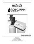
Owner’s Manual
©2002,2003,2004
Manufactured by:
HELLENBRAND, INC.
404 Moravian Valley Road • PO Box 187
Waunakee, Wisconsin 53597
Phone: 608-849-3050 • Fax 608-849-7398
Web: www.hellenbrand.com • Email: [email protected]
This owner’s manual is designed to assist owners and installers with the operation, maintenance and installation of your new water
softener. It is our sincere hope that this manual is clear, concise and helpful to both owner and installer. We have included detailed
instructions on general operating conditions, pre-installation and installation instructions, start-up, and timer and meter programming.
We have included a troubleshooting guide, service instructions and parts diagrams to assist you.
Owners will appreciate the simplified, illustrated format for operation, programming and troubleshooting. In the event that you
need professional assistance for servicing your water softener, please contact the dealer who installed this system.
TABLE OF CONTENTS
Frequently Asked Questions .................................................................................................................................................................. 2
Job Specification Sheet ............................................................................................................................................................... Page 3
Soft Water Basics ................................................................................................................................................................................... 4
Operating Conditions .............................................................................................................................................................................. 4
Pre-Installation Check List ..................................................................................................................................................................... 5
Installation Instructions ........................................................................................................................................................................... 6
Programming .................................................................................................................................................................................... 7-11
Water Softener Disinfection ................................................................................................................................................................. 12
Water Softener Draining Procedure ..................................................................................................................................................... 12
Trouble Shooting ............................................................................................................................................................................ 13-14
Parts Diagrams ............................................................................................................................................................................... 15-20
Specifications ................................................................................................................................................................................. 21-23
Warranty ............................................................................................................................................................................................... 24
FREQUENTLY ASKED QUESTIONS
1. Do I still use the same amount of soap in the dishwasher and clothes washer and showers now that I have a water
softener? No, the Water Quality Association states soft water can save up to 55% on detergent use. Start with using half the
amount of detergent previously used, this can be adjusted up or down based on preference. Soft water helps fabrics last longer,
because hardness minerals combined with soap can make fabric fibers brittle.
2. What is the health impact of drinking soft water? The sodium added to water by a softening is a non-issue most of the time,
even for people on a sodium-restricted diet. One could soften up to 75 grains per gallon water with sodium chloride and still be
well with the US Food and Drug Administration’s labeling of a “Low Sodium” beverage. People on a sodium-restricted diet should
consult their physician.
3. Should I use soft water for my plants? Some plants may be sensitive to even minute amounts of sodium. Suggest using hard
water for watering plants, often a kitchen cold faucet is plumbed for hard water or the outside faucets are usually plumbed for hard
water. If not, you can place your softener on bypass and fill water containers at the closest sink. Water from a reverse osmosis
system can always be used to water plants.
4. Will water spots disappear now that I have soft water? Water spots caused by hardness scale will disappear with a functioning water softener. However, other natural minerals dissolved in the water in high enough concentrations may cause spotting.
These mineral spots will be much easier to wipe away compared to hardness spotting.
5. Will soft water cause my water or ice cubes to look or taste different? Most people can tell the difference in taste between
hard and soft water, it is a personal preference. Ice cubes will appear the same, they may look cloudy due to air in water or
dissolved minerals, and this will not change because now they are made with softened water. A reverse osmosis drinking water
system will provide clearer ice cubes.
Dealer Name _________________________________________ Phone ________________________________________
Address ______________________________________________________________________________________________
_____________________________________________________________________________________________
2
JOB SPECIFICATION SHEET
MODEL NO. ___________________________________________________________________________________________
*WATER TEST AT TIME OF INSTALLATION
_______ Hardness CaCo3 (gpg)
______ Other______________________
_______ Iron (ppm)
______ Other______________________
_______ pH
______ Other______________________
*SIZING INFORMATION
All Water is Softened Except:
_______ Rear Hose Bib
_______ Front Hose Bib _______ Kitchen Cold _______ Toilets _______ All Cold
_______ Other _________________________________________________________________________________________
The average family uses 75 gallons per person daily for all water uses in the home, about 50 gallons per person daily if soft water
is not supplied to the toilets, and about 30 gallons per person daily if only hot water is softened.
_______ Daily Water Usage (Gallons/Person)
x _______ Family Size (Number of people in family)
= _______ Total Gallons Per Day
x _______ Grains Per Gallon of Hardness
(Note: Add 3 grains per gallon of hardness for each ppm iron for total compensated hardness)
= _______ Total Grains Per Day
*INSTALLATION DATE __________________________________________________________________________________
*SERIAL NUMBER _____________________________________________________________________________________
NOTES ______________________________________________________________________________________________
______________________________________________________________________________________________________
3
SOFT WATER BASICS
Hardness
Excess amounts of calcium and magnesium in water produce
hardness. A water softener removes the majority of calcium
and magnesium to produce softened water.
Hardness is measured in terms of grains. (This grain
weight is derived from the average weight of a dry grain of
wheat.) When your water is tested the grain hardness is
calculated and expressed as grains per gallon (gpg). This
calculation, as well as the number of people in your household
will help determine what type and size of water softener will
most efficiently soften your water.
Your water softener contains an ion exchange
media (sometimes called resin) which removes the hardness
from water as it flows through the softener tank. Eventually so
much hardness collects on the exchange media that the softener can no longer soften water. At this point it is considered
"exhausted". Regeneration is now necessary.
Regeneration
To regenerate the exchange media, it must be rinsed with a
brine (salt) solution. This removes the hardness from the exchange media and replaces it with sodium. The exchange media
is then ready to remove hardness from water. The hardness
minerals and excess brine solution are rinsed down the drain.
During the regeneration cycle the softener is also
backwashed. This reversing of the normal flow of water serves
to remove sediment which may have accumulated during the
softening process due to the filtering action of the exchange
media. Backwashing also loosens and fluffs up the bed of
exchange media to insure that during regeneration the brine
solution will come into contact with all the media.
Figure 1
Maintenance of Your Softener
Salt: Salt to a softener is what gasoline is to a car. Not only must a softener have salt, but it should be the proper type to insure
efficient recharging of the unit. Ask your dealer what type of salt may best suit your needs. Always have an adequate supply of salt on
hand. Check the salt level of your brine tank every couple of weeks initially to determine how much salt you use - this will depend on
how much water you use. As a rule of thumb, with 20 gpg hard water, about a 1/2 lb. of salt per person per day is used. In other words,
a family of four uses 60 lbs. of salt a month. If your household does not use much water, do not fill your salt keeper over 1/2 full, salt
bridging may occur in the brine tank. This may result in hard water due to ineffective regeneration. Fill the tank approximately threefourths full, with a minimum of 12” of salt. DO NOT USE Block Salt when the ProMate control is programmed with a brine tank prefill.
Block salt does not dissolve quick enough to provide a good regeneration.
Cleaning Salt Keeper: Salt keeper may require periodic cleaning. Inspect the salt keeper at least once a year for buildup of
insoluble materials. It is recommended to periodically clean the salt keeper no matter what kind of salt you are using. See page 9,
miscellaneous #3 for details on cleaning.
REMEMBER: Salt is the fuel to run your water softener. Buy the best clean salt available.
OPERATING CONDITIONS
Your water conditioner has been designed to adequately
handle up to 100 grains per gallon of hardness that might be
encountered as well as up to 2 ppm of Ferrous Bicarbonate
Iron. This is iron that is dissolved in an oxygen-free water supply.
It is not visible to the eye in a freshly drawn sample because the
water appears clear. But upon standing in contact with air, the
ferrous iron will become oxidized to the ferric state and start to
precipitate as a reddish brown floc. It can then be seen and if
allowed to remain in the supply will cause discolored water. In
order for your conditioner to remove the iron, air (oxygen) must
4
be kept from coming in contact with water until after it has been
passed through the water conditioner. In some cases, additional
equipment may be required to treat water supplies having
special characteristics, such as: ferric hydroxide iron, iron bacteria, low pH, taste and odors, etc. If any question should exist,
contact your dealer.
This water softener is not intended to be used for treating
water that is microbiologically unsafe or of unknown quality without adequate disinfection before or after treatment.
PRE-INSTALLATION CHECK LIST
(All electrical & plumbing should be done in accordance to all local codes)
Water Pressure: A minimum of 20 pounds of water pressure
(psi) is required for regeneration. Maximum 120 psi.
Water Quality: On rural water supplies there is often a problem
with sand or sediment in the water. (This problem occasionally
occurs in public water supplies.) If the water is not filtered
before being softened, the sand and sediment will plug up the
water softener restricting the flow through the resin bed. This
problem often requires rebedding of the mineral tank. Note:
Well and/or pump problems affecting the operation of the
softener are repairs that are not covered under warranty. To
prevent these unnecessary, and expensive repairs that are not
covered under warranty, we recommend the installation of an
in-line filter system ahead of softener installations.
Electrical: A continuous 110 volt 60 cycle current supply is
required. Make certain the current supply is uninterrupted and
cannot be turned off with another switch. All electrical connections
must be connected per local codes. Surge protection is
recommended with all electric controls.
Existing Plumbing: Condition of existing plumbing must be
Figure 4
free from lime and iron build-up. Piping that is built-up heavily
with lime and/or iron must be replaced. If piping is blocked with
iron, additional equipment must be installed ahead of the water
conditioner to correct the problem.
Drain Line: The conditioner should be located close to a drain.
Avoid overhead drain lines if possible to prevent back pressure
on the brine injector. Overhead drains are not to exceed 8 feet
above the floor and no more than 20 feet in length. The pipe
size for the drain line should be a minimum of 3/4”. Backwash
flow rates in excess of 7 gpm or length in excess of 20’ require
1” drain line.
Bypass Valves: Always provide for the installation of a bypass valve.
Softening: It is recommended that the conditioner be installed
to soften both the hot and cold water supply. A separate hard
water faucet may be plumbed for drinking purposes if you
desire. Outside faucets should be left on hard water.
Caution: Water temperature is not to exceed 110°F; the
conditioner cannot be subject to freezing conditions, or to a
vacuum due to loss of pressure (such as a water main break).
Figure 5
5
INSTALLATION INSTRUCTIONS
(All electrical & plumbing should be done in accordance to all local codes)
•
Do not use vaseline, oils, other hydrocarbon lubricants or
spray silicone anywhere. A silicon lubricant may be used on
black o-rings but is not necessary. Avoid any type of
lubricants, including silicone, on red or clear lip seals.
•
Do not use pipe dope or other sealants on threads. Only
teflon tape may be used on threads. Teflon tape is not
necessary on the nut connection or caps because of o-ring
seals.
•
The pipe size for the drain line should be a minimum of 3/4”.
Backwash flow rates in excess of 7 gpm or length in excess
of 20’ require 1” drain line.
1. Place the conditioner where you want to install it, making
sure it is on a clean, level and firm base.
2. Do all necessary plumbing (inlet to inlet, outlet to outlet and
drain line to drain). The control valve, fittings and/or bypass
are designed to accommodate minor plumbing
misalignments but are not designed to support the weight of
a system or the plumbing.
3. When assembling the installation fitting package (inlet and
outlet), connect the fitting to the plumbing system first and
then attach the nut, split ring and o-ring. Heat from soldering
or solvent cements may damage the nut, split ring or o-ring.
Solder joints should be cool and solvent cements should be
set before installing the nut, split ring and o-ring. Avoid
getting primer and solvent cement on any part of the o-rings,
split rings, bypass valve or control valve.
4. A jumper ground wire should be installed between the
inlet and outlet pipe whenever the metallic continuity of
a water distribution piping system is interrupted. Install grounding strap on metal pipes.
5. The drain connection may be made using either 5/8” polytube
(See figure 6a, page 5) or a 3/4” female adapter. If
soldering, joints near the drain must be done prior to
connecting the drain line flow control fitting. Leave at least
6” between the drain line control fitting and solder joints
when soldering pipes that are connected on the drain line
control fitting. Failure to do this could cause interior damage
to the drain line flow control fitting.
6. The brine refill flow control assembly is installed in an easy
to access refill elbow located on top of the control valve. The
refill flow control assembly is attached to the control valve
with a locking clip. The locking clip allows the elbow to
rotate 270 degrees so the outlet can be orientated towards
the saltkeeper.
7. Connect the brine line found in the brine tank to the brine
connection on the control valve. The control valve has a
standard refill elbow which a 3/8” flexible tube can be
connected, see figure 6a, page 5. (An optional elbow can
be ordered which accommodates a 1/2” flexible tube for a
high regenerant draw rate situation). Both elbows use the
same refill flow control and retainer. Do not connect the
other end of the brine line to the safety brine valve in the
brine tank at this time. Make sure the floor is clean beneath
the salt tank and that it is level and smooth.
8. A 1/2” (inside diameter) gravity drain line may be connected
to the overflow fitting on the side of the brine tank. This
overflow is in case of a malfunction in the brine shut off. If
the unit is installed where water may flow in the event of an
overflow and cause water damage, connect a length of
flexible tubing and run to a drain below the level of the
overflow. (Do not connect the tubing to the drain line on
the control valve. Do not run tubing above overflow
height at any point.)
1”
Drain
Connection
Brine Line
Connecton
Figure 6a
6
Figure 6b
PROGRAMMING
Initial Start Up
The initial start up will probably be done by the technician
installing the softener system. If not, the following instructions
will step you through the process.
1. Complete all plumbing connections: inlet, outlet, drain
line and brine line. Do not add salt at this time.
2. Place the bypass valve in the bypass position. (See
figure 3 page 4) Turn on the main water supply. Open
a cold soft water faucet to flush the piping of any air
and/or foreign material. Run until the water is clear.
3. Manually add 6 inches of water to the brine tank.
4. Now plug the transformer into a 110-volt receptacle.
(Be certain the outlet is uninterrupted.) Within 5
seconds the control will automatically align itself into
the softening mode and the display will flash 12:00 (am).
(Figure 7, page 6).
5. Set the time of day. (figure 8, page 7)
6. Push REGEN button and hold it down for 3 seconds.
The system will advance to the “First” position. (Note:
Depending on how the system is programmed it could
read backwash, rinse, brine or fill). Keep pushing
REGEN button until “Rinse” shows in the lower right
hand corner of display. Slowly place the by-pass into
the “diagnostic mode” (see fig 4, page 5). Run water
to the drain until it runs clear. Return the by-pass valve
to the by-pass position (fig 3, page 5). Push REGEN
button until “Time” appears in upper left hand corner
of display.
7. Once again, push REGEN button and hold down for 3
seconds. Keep pushing REGEN button until “Backwash” appears. Slowly place the by-pass valve into
8.
the “Diagnostic Mode” 1/2 way. Allow water to slowly
fill the mineral tank. When a solid stream of water
starts coming out of the drain line, open the by-pass
inlet valve all the way and allow to run out the drain
until water clears. Then slowly place the by-pass into
the “normal operation” mode by opening the outlet
side of by-pass valve, figure 2, page 4.
Press the regen button until LED display says “BRINE”.
7
STEP 1
SET TIME OF DAY
➔
Step 1 - Press SET CLOCK.
STEP 2
Step 2 - Current Time (hour): Set the hour of the day using ▲ or ▼ buttons. AM/
PM toggles after 12. Press NEXT to go to step 3.
Step 3 - Current Time (minutes): Set the minutes of day using ▲ or ▼ buttons.
Press NEXT to exit Set Clock. Press REGEN to return to previous step.
➔
Power Loss - If the power goes out for less than two hours, the system will
automatically reset itself. If an extended power outage occurs, the time of day
will flash on and off which indicates the time of day should be reset. The system
will remember the rest of the program settings. Do not forget to reset for daylight
savings time.
STEP 3
Figure 9
STEP 1
➔
Step 1 - Press NEXT and ▲ simultaneously for 3 seconds.
STEP 3
Step 2 - Hardness: Set the amount of total compensated hardness in grains (hardness as
calcium carbonate) per gallon using ▲ or ▼ buttons. The default is 20 with value ranges from 1 to
150 in 1 grain increments. Note: The grains per gallon should be increased if soluble iron needs
to be reduced. Add 3 grains of hardness for each ppm of iron present. If this display shows nA , then system is either set-up in “time clock” or “filter” modes. (See page 23). Press NEXT to go to
Step 3. Press REGEN to exit Installer Displays/Settings.
➔
STEP 2
➔
STEP 4
Step 3 - Day Override: This sets the number of days between regenerations. If value set to
“oFF” regeneration initiation is based solely on gallons used. If value is set as a number (allowable range from 1 to 28) a regeneration initiation will be called for on that day even if sufficient
number of gallons were not used to call for a regeneration. Set Day Override using ▲ or ▼
buttons:
• number of days between regeneration (1 to 28); or
• “oFF”
➔
See figure 12a & b, page 10-11, for more detail on softener setup. Press NEXT to go to step 4.
Press REGEN to return to previous step.
STEP 5
➔
RETURN TO
NORMAL MODE
Figure 10a
8
INSTALLER DISPLAYS/SETTINGS
Step 4 - Next Regeneration Time (hour): Set the hour of day for regeneration using ▲ or ▼
buttons. AM/PM toggles after 12. The default time is 2:00 a.m. This display will show “REGEN”
on 0 GAL if system is set for immediate regeneration. See table 6, page 19. Press NEXT to go to
step 5. Press REGEN to return to previous step.
Step 5 - Next Regeneration Time (minutes): Set the minutes of day for regeneration using ▲ or
▼ buttons. This display will not be shown if system is set for immediate regeneration. Press
NEXT to exit Installer Displays/Settings. Press REGEN to return to previous step.
SET SALT MONITOR OPTION
NOTE: This screen will not appear if system is set up as a filter or the 'set low salt
warning' is set to off. See dealer for details
Step 1US - Press the NEXT button until SALT appears in the display. It does not matter if the
SALT display alternates with the LBS REMAINING display.
Step 2US - Press SET CLOCK
Step 3US - Set LBS REMAINING: Use the ▼ or ▲ button to adjust the pounds remaining in
the brine tank.
NOTE: Estimate the pounds of salt in the brine tank and add it to the amount of salt added
to the brine tank. The example at the left would indicate 200 lbs. of salt being added to a
brine tank that has 40 lbs. remaining.
Step 4US - Press SET CLOCK to exit Adding Salt.
NOTE: The salt used per regeneration setting can be set in increments
of 0.1 pounds, but LBS REMAINING screen will round up or down to the
closet whole number.
Once the salt remaining as gone below the set point the display will
automatically flash Salt Fill.
RETURN TO
NORMAL MODE
Figure 10b
Regeneration Mode
Typically a system is set to regenerate at a time of low water usage. An example
of a time with low water usage is when the household is asleep. If there is a demand
for water when the system is regenerating, untreated water will be supplied.
Regeneration Step #2
(shows time remaining in regen step is 8:22)
When the system begins to regenerate, the display will change to include
information about the step of the regeneration process and the time remaining for
that step to be completed. The system runs through the steps automatically and
will reset itself to provide treated water when the regeneration has been completed.
Manual Regeneration
Sometimes there is a need to regenerate the system, sooner than when the
system calls for it, usually referred to as manual regeneration. There may be
a period of heavy water usage because of guests or a heavy laundry day.
To initiate a manual regeneration at the preset delayed regeneration
time, press and release “REGEN”. The words “REGEN TODAY” will flash
on the display to indicate that the system will regenerate at the preset
delayed regeneration time. If you pressed the “REGEN” button in error,
pressing the button again will cancel the request.
To initiate a manual regeneration immediately, press and hold the “REGEN”
Figure 11
button for three seconds. The system will begin to regenerate immediately.
The request cannot be cancelled. You must cycle all the way through the cycles to make it stop. PLEASE NOTE: This will reset the meter.
Note: If the salt keeper does not contain salt. Fill with salt and wait at least two hours before regenerating.
9
CYCLE TIME ADJUSTMENTS
Normally it is not recommended to adjust the lengths of the cycle times. However, certain water conditions may
dictate adjustments. This should only be done from the recommendation of a water conditioning professional.
The following charts shows the upper and lower limits of each cycle.
Cycle Options
Fill
Softening (Service)
Backwash
Brine
Units
Lbs.
Minutes
Minutes
Minutes
Lower/Upper Limit
0.1 to 99.9
1 to 999
1 to 999
1 to 999
Factory Setting
See Page 20
120
8
60
STEP 1S
STEP 1S – Press NEXT and ▼ simultaneously for 3 seconds. If screen in Step
2S does not appear in 5 seconds the lock on the valve is activated.
STEP 2S
STEP 2S – Choose SOFTENING using ▼ or ▲ button. Press NEXT to go to
Step 3S. Press REGEN to exit Softener System Setup.
STEP 3S – Select the time for the first cycle (which in this example is FILL)
using the ▼ or ▲ button. Press NEXT to go to Step 4S. Press REGEN to
return to previous step.
STEP 4S – Select the time for the second cycle (which in this example is
SOFTENING) using ▼ or ▲ button. Press NEXT to go to Step 5S. Press
REGEN to return to the previous step.
STEP 5S – Select the time for the third cycle (which in this example is BACKWASH) using the ▼ or ▲ button. Press NEXT to go to Step 6S. Press
REGEN to return to the previous step.
STEP 6S – Select the time for the fourth cycle (which
in this example is dn BRINE) using the ▼ or ▲ button.
Press NEXT to go to Step 7S. Press REGEN to return
to the previous step.
STEP 7S – Select the time for the fourth cycle (which in this example is dn
BRINE) using the ▼ or ▲ button. Press NEXT to go to Step 8S. Press
REGEN to return to the previous step.
Figure 12a
10
STEP 8S
STEP 8S – Select the time for the fourth cycle (which in this example is RINSE) using
the ▼ or ▲ button. Press NEXT to go to Step 9S. Press REGEN to return to the
previous step.
RINSE
STEP 9S
STEP 10S
STEP 11S
STEP 12S
STEP 9S - Set Grain Capacity using the ▼ or ▲ button. The ion exchange capacity
is in grains of hardness as calcium carbonate for the system based on the pounds of
salt that will be used. Calculate the pounds of salt using the fill time previously
selected. The allowable grains capacity range varies from 5,000 to 200,000 grains.
The increment increase is 500 for the range from 5000 to 30,000; 1000 for the range
of 30,000 to 100,000; and 2000 for the range of 100,000 to 200,000. Grains capacity
is affected by the fill time. The grains capacity for the selected fill time should be
confirmed by testing. The capacity and hardness levels entered are used to automatically calculate reserve capacity when gallon capacity is set to AUTO. Press NEXT to
go to Step 10S. Press REGEN to return to previous step.
STEP 10S – set Gallons Capacity using ▼ or ▲ button. If value is set to:
• “AUTO” gallon capacity will be automatically calculated and reserve capacity will be
automatically estimated;
• “oFF” regeneration will be based solely on the day override set (see Installer Display/Settings Step 3I); or
• as a number (allowable range 20 to 50,000) regeneration initiation will be based off
the value specified.
Increment increase is 20 for the range 20 to 1000, 50 for the range of 1000 to 10,000
and 100 for the range of 10,000 to 50,000.
If “oFF” or a number is used, hardness display will not be allowed to be set in Installer
Displays/Settings Step 2I. See Table 8 for more detail. Press NEXT to go to Step
11S. Press REGEN to return to previous step.
STEP 11S – Set Regeneration Time Options using the ▼ or ▲ button. If value is set
to:
• “NORMAL” means regeneration will occur at the preset time;
• “on O” means regeneration will occur immediately when the gallons capacity
reaches 0 (zero); or
• “NORMAL + on 0” means regeneration will occur at one of the following:
- the preset time when the gallons capacity falls below the reserve or the specified
number of days between regenerations is reached, whichever comes first; or
- immediately after 10 minutes of no water usage when the gallon capacity reaches 0 (zero).
See page 23 for more options. Press NEXT to go to Step 12S. Press REGEN to
return to previous step.
STEP 12S – Set Low Salt Warning using the ▼ or ▲ button. If value is set to:
• “oFF” no low salt level warning will appear for the user,
or
• a specific value “FILL SALT” will flash on the display
when the calculated remaining pounds of salt falls below
that level. Allowable values range from 10 to 400 pounds
in 10 pound increments.
Press NEXT to exit Softener System Setup. Press
REGEN to return to previous step.
Figure 12b
11
WATER SOFTENER DISINFECTION
The materials of construction of your water softener will not
support bacterial growth nor will these materials contaminate a
water supply. However, the normal conditions existing during
shipping, storage, and installation indicate the advisability of
disinfecting a softener after installation, before the softener is
used to treat potable water. In addition, during normal use a
softener may become fouled with organic matter or in some
cases, with bacteria from the water supply.
Therefore, every water softener should be disinfected
after installation, some will require periodic disinfection during
their normal life. Disinfect as follows:
5.25% SODIUM HYPOCHLORITE solutions are available
under such trade names such as Clorox, Linco, Bo Peep,
White Sail and Eagle Brand Bleach. If stronger solutions
are used, such as those sold for commercial laundries,
adjust the dosage accordingly.
1. Dosage:
a. Softening resin; 1.2 fluid ounce per cubic foot of
mineral (see page 18).
2. Add the required amount of hypochlorite solution to the
brine well of the brine tank.
a. Proceed with the normal regeneration. Press regen
and allow the water softener to go through a normal
regeneration.
SODIUM HYPOCHLORITE (household bleach)
WATER SOFTENER DRAINING PROCEDURE
In cold weather climates it is common for plumbing systems that
are not in use to be “winterized“ or drained of all water to prevent
any damage that may be caused by the excessive expansion of
water when it freezes. To prevent damage to a water softener
it must be properly drained also. A simple way to properly drain
or winterize a water softener is to use compressed air to force
all of the water out of the softener mineral tank. The following
procedure will explain the process:
1) Initiate the softener into a manual regeneration cycle. After
the refill cycle, advance control to backwash and allow it to
complete the backwash cycle (this will clean the media) and
start into the brine-draw cycle. Allow the regeneration to
continue in the brine draw cycle until the brine is drawn out
of the salt keeper and the air check at the bottom of the brine
pick-up tube shuts off. At this time no more brine is introduced into the softener and the slow rinse process begins.
2) Turn the water supply inlet and outlet valves off to the water
softener as soon as the air check shuts off and no more
brine is being drawn into the softener (at the beginning of the
slow rinse process).
3) Unplug the electric power leaving the softener control valve
in the brine draw cycle.
4) Disconnect the brine tube at the top of the salt keeper and
force air into the brine tube toward the softener mineral tank
and control valve. The air will force the brine/water solution
that was drawn into the mineral tank out to drain through the
control valve drain line. (An air compressor blow gun attachment with a portable air compressor works well.)
CAUTION: You do not want to apply any more pressure than
necessary to force the brine/water out of the mineral tank.
The small amount of brine/water that may be left in the
mineral tank will not expand enough to cause any damage
to the softener when it freezes.
If your softener is equipped with an optional bottom drain on
the mineral tank, you will have to follow all of the same
procedures with the exception of the need for compressed
air. With the brine tube disconnected from the salt keeper,
raise it to a level above the softener control valve and
temporarily secure it in this position. Now open the drain
valve at the bottom of the mineral tank and allow all brine/
water to drain from the mineral tank.
CAUTION: If a hose is connected to the drain valve to direct
the brine/water to a floor drain be sure it runs downward and
is unobstructed. When brine/water quits running at the drain,
be sure to leave the drain valve open until you start the
system up again.
5) At this time the salt keeper has very little water left in it. What
liquid is left in the salt keeper is saturated brine, provided that
there is still salt left in the tank. Saturated brine will not freeze
solid and cause any damage and does not have to be drained
any further from the brine tank.
If there is no salt left in the salt keeper when the system is
drained we recommend dumping all of the water out of the
brine tank at this time. See brine tank cleaning instructions.
(#3 in miscellaneous section, below)
6) CAUTION: It is important at this time to be assured that the
inlet/outlet water supply piping is properly drained. Depending on how the water supply piping was routed to the water
softener control valve, a water loop or trap may have been created.
Sometimes drain valve(s) are installed at the bottom of the
loop to assure all water can be drained out. If not it may be
necessary to disconnect the control valve from the piping
system and open the inlet/outlet valve(s) to allow all the water
to drain from the piping. This should be done when the rest
of the plumbing system is drained.
7) Draining or winterizing of your softener is complete. Refer to
the start-up procedures on page 6 when you are ready to start
your softener.
MISCELLANEOUS
1. Salt Usage: See your water conditioning professional for a
recommendation on the best type of salt for your application.
2. Brine Tank Cleaning:
a. Remove brine tank cover.
b. Scoop out as much old salt as possible.
c. Disconnect brine tubing from safety brine valve at brine well.
d. Remove safety brine valve from brine well.
e. Place one hand in brine well to hold overflow nut and
remove 2 piece overflow.
f. Remove optional brine well and grid plate, if used, from
saltkeeper.
g. Remove any remaining salt and/or impurities from brine tank.
h. Using clean water and a brush or rag, wipe and rinse inside of
brine tank. Also wipe and rinse the grid plate and brine well.
12
i.
Reassemble brine tank reversing steps c - f. Note: If grid
plate is used and it is damaged or cracked, replace with new one.
j. Put brine tank in place making sure there is no debris or
foreign material beneath it.
k. Reconnect brine tubing to safety brine valve.
l. Manually add 6 inches of water to the saltkeeper (or to
approximately 1” above the grid plate, if used).
m. Add new salt. Important: Do not add the old salt which was
removed earlier unless it is clean and not mushy. We
recommend using new salt.
n. Follow the disinfection instructions found on page 8.
o. Put on brine tank cover.
TROUBLE SHOOTING
PROBLEM
1. ERROR followed by code number
Error Code 1001 - Unable to recognize
start of regeneration
Error Code 1002 - Unexpected stall
Error Code 1003 - Motor ran to long,
timed out trying to reach next cycle
position
Error Code 1004 - Motor ran to long,
timed out trying to reach home
position
If other Error Codes display
contact the factory
CAUSE
A. Control valve has just been serviced
B. Foreign matter is lodged in control valve
C. High drive forces on piston
D. Control valve pistion not in home position
E. Motor not inserted fully to engage pinion,
motor wires broken or disconnected,
motor failure
F. Drive gear label dirty or damaged,
missing or broken gear
G. Drive bracket incorrectly aligned to
back plate
H. PC board is damaged or defective
I. PC board incorrectly aligned to
drive bracket
CORRECTION
A. Press NEXT and REGEN for 3 seconds or
unplug power source jack (black wire) and plug
back in to reset control valve
B. Check piston and spacer stack assembly
for foreign matter
C. Loosen drive cap assembly 1/4 turn or replace
D. Press NEXT and REGEN for 3 seconds or unplug
power source jack (black wire) and plug back in
to reset control valve
E. Check motor and wiring. Replace motor if
necessary
F.
Replace or clean drive gear
G. Reseat drive bracket
H. Replace PC board
I. Ensure PC board is correctly snapped on to
drive bracket
2. Error Code 4003
A. Possible low voltage through circuit board
or miscommunication on board at start-up
A. Unplug power supply from board, re-apply power.
If this does not solve the problem, replace PC board
3.Control valve stalled in regeneration
A.
B.
C.
D.
E.
F.
G.
Motor not operating
No electric power at outlet
Defective transformer
Defective PC board
Broken drive gear or drive cap assembly
Broken piston retainer
Broken main or regenerant piston
A.
B.
C.
D.
E.
F.
G.
Replace Motor
Repair outlet our use working outlet
Replace transformer
Replace PC board
Replace drive gear or drive cap assembly
Replace drive cap assembly
Replace main or regenerant piston
4. Control valve does not regenerate
automaticallly when REGEN button
is depressed and held
A.
B.
C.
D.
Transformer unplugged
No electric power at outlet
Broken drive gear or drive cap assembly
Defective PC board
A.
B.
C.
D.
Connect transformer
Repair outlet or use working outlet
Replace drive gear or drive cap assembly
Replace PC board
5. Control valve does not regenerate
automatically but does when
REGEN button is depressed
A. By-pass valve in bypass position
B. Meter connection disconnected
C. Restricted/stalled meter turbine
D. Defective meter
E. Defective PC board
F. Set-up error
A. Put control valve in service position
B. Connect meter to PC board
C. Remove meter and check for rotation
or foreign matter
D. Replace meter
E. Replace PC board
F. Check control valve set-up procedure
6. Time of day flashes on and off
A. Power has been out more than two hours,
the transformer was unplugged and then
plugged back into the wall outlet, the
transformer plug was unplugged and then
plugged back into the board or the NEXT
and REGEN buttons were pressed to
reset the valve
A. Reset the time of day
7. Softener delivers hard water.
A. Bypass valve is open or faulty.
B. No salt or low salt level in brine tank.
A. Close bypass valve or replace.
B. Add salt to brine tank and maintain salt level
above water level.
C. See problem #11.
D. Check gallon capacity settings.
E. Check brine refill setting and refill flow restrictor for
blockage.
F. See problem #8.
G. Test meter and clean or replace meter.
H. Test raw water hardness and adjust settings to
highest known hardness.
C. Softener fails to draw brine.
D. Excessive water usage.
E. Insufficient brine level in brine tank.
F. Resin level inadequate.
G. Meter faulty.
H. Raw water hardness fluctuation.
8. Unit uses too much salt.
A. Improper brine refill setting.
B. Improper settings.
C. Excessive water in brine tank.
D. Leaking faucets, toilets, etc...
A. Check brine refill setting for proper salt dosage
B. Check water hardness and reevaluate capacity setting
specification
C. See problem #10.
D. Repair or replace those items.
13
TROUBLE SHOOTING
PROBLEM
9. Loss of resin.
CAUSE
A. Backwash controller missing.
B. Faulty distributor tube assembly.
C. Air in water supply system.
A. Install backwash controller.
B. Check distributor tube assembly for cracks or holes.
C. 1. Check for leaks in brine lines, fittings, or air check.
Repair or replace.
2. Install upper distributor.
3. Ensure that water supply system has an air
eliminator.
A. Low water pressure.
B. Excessive water in brine tank.
C. Wrong size injector.
A. Check incoming water pressure - Must remain at
minimum of 25 psi.
B. See problem #10.
C. Install correct injector.
11. Excessive water in brine tank.
A.
B.
C.
D.
E.
Plugged injector.
Faulty piston assembly.
Plugged or kinked drain line.
Backwash flow controller closed off.
Defective brine line flow control.
A.
B.
C.
D.
E.
Remove injector and clean ports.
Replace piston assembly.
Inspect drain line for kinks or plugging.
Check backwash flow controller.
Replace brine refill flow control.
12. Softener fails to draw brine.
A.
B.
C.
D.
E.
F.
Injector is plugged.
Faulty piston assembly.
Brine line connection leak.
Drain line plugged creating excess back pressure.
Drain line too long or too high
Low inlet pressure.
A.
B.
C.
D.
E.
F.
Remove injector and clean ports.
Check piston assembly.
Inspect brine line during refill cycle for leaks.
Inspect drain line for blockage.
Refer to drain line specifications.
Increase inlet pressure to a minimum of 25 psi.
13. Continuous flow to drain.
A.
B.
G.
A.
B.
Piston assembly failure.
Motor failure.
Circuit board failure.
Iron build-up in resin.
Resin bed fouled with sand or sediment.
A.
B.
G.
A.
B.
10. Softener delivers salt water.
14. Loss of water pressure.
C. Resin bed mushing due to high amount
of oxidizers in water supply (chlorine).
15. Iron in softened water.
A. Iron has fouled resin bed.
Replace piston assembly.
Replace motor.
Replace circuit board.
See problem #14.
Rebed softener and install sediment filter ahead
of softener.
C. Rebed softener. Install dechlorinaton system
C. Prefilter failure.
D. Iron level excessive.
E. Control fails to regenerate.
A. Use iron reducing resin cleaner to cleanse resin bed,
and increase salt dosage or regenerate more
frequently. Install an Iron Curtain System ahead
of the softener.
B. Test water to determine type of iron, install iron
reduction system.
C. Check prefilter.
D. Install iron reduction system.
E. See problem #4.
16. Control does not display time of day
A.
B.
C.
D.
A.
B.
C.
D.
17. Control does not display correct
time of day
A. Switched outlet
B. Power outage
C. Defective PC board
A. Use uniterrupted outlet
B. Reset time of day
C. Replace PC board
18. No “softening” or “filtering” display
when water is flowing
A. Bypass valve in bypass position
B. Meter connection disconnected
C. Restricted/stalled meter turbine
D. Defective meter
E. Defective PC board
A. Put bypass valve in service position
B. Connect meter to PC board
C. Remove meter and check for rotation, clean
foreign material
D. Replace meter
E. Replace PC board
A.
B.
C.
D.
A.
B.
C.
D.
B. Iron is not in a soluble state.
19. Control valve regenerates at
wrong time of day
14
CORRECTION
Transformer unplugged
No electric power at outlet
Defective transformer
Defective PC board
Power outages
Time of day not set correctly
Time of regeneration incorrect
Control valve set at “on 0”
(immediate regeneration)
E. Control valve set at NORMAL + on 0
Connect power
Repair outlet or use working outlet
Replace transformer
Replace PC board
Reset control valve to correct time of day
Reset to correct time of day
Reset regeneration time
Check control valve set-up procedure
regeneration time option (see table 6, page 19)
E. Check control valve set-up procedure
regeneration time option (see table 6, page 19)
PROMATE-1 CONDITIONER & SALT KEEPER ASSEMBLIES
Item
1
2
3&4
Description
Control Center-Metered
Control Center-Time Clock
Top Diffuser
Mineral Tank Assembly
Qty
1
1
1
5
6
7-15a
b
c
7
8a
b
c
9a
b
c
10-14 a
b
10
11*
12
13
14 a
b
15
16 a
b
–
PM-24 8 x 44
PM-32 9 x 48
PM-48 10 x 44
PM-48 10 x 54
PM-64 13 x 54
PM-96 14 x 65
PM-128 16 x 65
PM-160 18 x 65
PM-192 20 x 62
Ion Exchange Resin
Underbedding
Salt Keeper Assy (18x40)-Granite
Salt Keeper Assy (24x41)
Salt Keeper Assy (24x50)
3/8” x 6” Brine Line
18x40 Salt Keeper Tank-Granite
24x41 Salt Keeper Tank-Black
24x50 Salt Keeper Tank-Black
Salt Keeper Cvr 18x40
Salt Keeper Cvr 24x41
Salt Keeper Cvr 24x50
Safety Brine Valve Assy 41”
Safety Brine Valve Assy 50”
Cap, Brine Well
Safety Brine Valve
Float Assembly
Air Check
Brine Well 40”-41”
Brine Well 50”
2-Piece Overflow
Grid Plate 18” (optional)
Grid Plate 24” (optional)
Owners Manual
1
1
1
1
1
1
1
1
1
*
*
1
1
1
1
1
1
1
1
2
1
1
1
1
1
1
1
1
Part #
60-PM1-ED (see pages 13-17 for detailed components)
60-PM1-TC
9-D1203
Item 3 only
Item 4 only
Not Shown
Mineral Tank
Distributor Assy
Granite Tank Jacket
19-RT0844NAT
9-93243-RT
99-162-7
19-RT0948NAT
9-93247-RT
99-164-7
19-RT1044NAT
9-93243-RT
99-166-7
19-RT1054NAT
9-93253-RT
99-168-7
19-RT1354NAT
9-93254-RT
19-RT1465NAT
9-93272-RT
Tank Adapter
19-RT1665NAT-4 9-93272-RT
19-020-RT
19-RT1865NAT-4 9-TO418 (Hub & Lateral) 19-020-RT
19-RT2062NAT-4 9-TO421 (Hub & Lateral) 19-020-RT
1-A4068
*See Specifications for amount
1-A8072
*See Specifications for amount
3-SB05-7
3-S405-3
3-S505-3
2-H1023-06
2-1840GR
2-2441BK
2-2450BK
2-G2191-60
Included with 8b
Included with 8c
2-H4700-39
2-H4700-46
2-H7016
Figure 13
2-H4600
2-H4640-9.5
2-H4500-48
2-H1030-36S
2-H1030-46S
2-H1018
2-H1072-01
2-H002
73-350
*
*Safety Brine Valve (Item 11)
Drawing for service only
Must be ordered complete
15
16
17
WATER METER AND METER PLUG
BYPASS VALVE
Not Shown
1
2
3
11*
15-V3191-01
15-V3151
15-V3150
15-V3105
15-V3191-01
Bypass 90º Vert. Assy.
Nut 1” Quick Connect
Split Ring
O-Ring 215
Bypass Verticle Adpt. Assy (set of 2)
2
2
2
1
19
INSTALLATION FITTING ASSEMBLIES
ITEM NO.
1
2
3
4
1-4
DESCRIPTION
ORDER NO.
15-V3151
15-V3150
15-V3105
15-V3149
15-V3007
Nut 1” Quick Connect
Split Ring
O-Ring 215
Fitting 1” PVC Male NPT Elb.
Fitting 1” PVC Male NPT Asy. (Set of 2)
20
QTY.
ITEM NO.
2
2
2
2
1
1
2
3
4
1-4
ORDER NO.
15-V3151
15-V3150
15-V3105
15-V3189
15-V3007-01
DESCRIPTION
Nut 1” Quick Connect
Split Ring
O-Ring 215
Fitting 3/4” & 1” PVC Solv. 90
Fitting 3/4” & 1” PVC Solv 90 (set of 2)
QTY.
2
2
2
2
1
ITEM NO.
1
2
3
4
1-4
ORDER NO.
15-V3151
15-V3150
15-V3105
15-V3164
15-V3007-04
DESCRIPTION
Nut 1” Quick Connect
Split Ring
O-Ring 215
Fitting 1” Plastic Male NPT
Fitting 1” Male NPT Asy. (Set of 2)
QTY.
ITEM NO.
2
2
2
2
1
1
2
3
4
1-4
Figure 26
ITEM NO.
1
2
3
4
1-4
ORDER NO.
15-V3151
15-V3150
15-V3105
15-V3317
15-V3007-05
DESCRIPTION
Nut 1” Quick Connect
Split Ring
O-Ring 215
Fitting 1-1/4” Plastic Male NPT
Fitting 1-1/4” Male NPT (Set of 2)
QTY.
2
2
2
2
1
Figure 27
ORDER NO.
15-V3151
15-V3150
15-V3105
15-V3316
15-V3007-06
DESCRIPTION
Nut 1” Quick Connect
Split Ring
O-Ring 215
Fitting 1” Plastic Male BSPT
Fitting 1” Male BST Asy. (Set of 2)
QTY.
2
2
2
2
1
Figure 28
21
PROMATE 1 SYSTEM SPECIFICATIONS
ED-“ELECTRONIC DEMAND”
TC-“TIME CLOCK”
MODEL
PM1-24ED
PM1-24TC
PM1-48ED
PM1-48TC
PM1-64ED
PM1-64TC
PM1-96ED PM1-128ED
PM1-96TC PM1-128TC
PM1-160ED
PM1-160TC
PM1-192ED
PM1-192TC
FACTORY PRESET MINUTES
Backwash-1; Min
Brine; Min.
Backwash-2; Min
Fast Rinse; Min
8
60
8
4
8
60
8
4
8
60
8
4
8
60
8
4
8
60
8
4
8
60
8
4
8
60
8
4
8
60
8
4
8
60
8
4
Refill-Minutes
-High Efficiency
-Low Salting
-Medium Salting*
-High Salting
3.0
4.0
5.0
7.5
4.0
5.3
6.7
10.0
4.0
5.3
6.7
10.0
6.0
8.0
10.0
15.0
8.0
10.7
13.5
20.0
12.0
16.0
20.0
30.0
16.0
21.3
27.0
40.0
20.0
26.7
33.5
50.0
24.0
32.0
40.0
60.0
Refill-Lbs of Salt
-High Efficiency
-Low Salting
-Medium Salting*
-High Salting
4.5
6.0
7.5
11.5
6.0
8.0
10.0
15.0
6.0
8.0
10.0
15.0
9.0
12.0
15.0
22.5
12.0
16.0
20.0
30.0
18.0
24.0
30.0
45.0
24.0
32.0
40.0
60.0
30.0
40.0
50.0
75.0
36.0
48.0
60.0
90.0
Capacity Grains
-High Efficiency
-Low Salting
-Medium Salting*
-High Salting
17,200
19,980
21,040
24,230
22,930
26,650
28,060
32,310
22,930
26,650
28,060
32,310
34,400
39,970
42,090
48,460
45,870
53,300
56,120
64,620
68,810
79,950
84,180
96,930
91,750
106,600
112,240
129,240
114,690
133,250
140,300
161,550
137,620
159,900
168,360
193,860
Water Usage (U.S. Gallons)
At Factory Settings
and 40 psi Inlet Pressure
44
54
68
69
127
134
179
245
272
Service Flow Rate;
Flow Rate @ 10 psi
9.8
10.1
11.3
10.5
14.2
14.4
15.1
17.3
17.8
Flow Rate @ 15 psi
Mineral; Cu Ft.
Underbedding;lbs
Mineral Tank Dimen.
Brine Tank Dimen.
Drain Line Flow Con
Brine Line Flow Con
Injector; color
13.1
0.75
8
8x44
18x40
1.3
0.5
C-Violet
13.0
1
11
9x48
18x40
1.7
0.5
D-Red
14.5
1
14
10x44
18x40
2.2
0.5
E-White
14.1
1.5
14
10x54
18x40
2.2
0.5
E-White
18.2
2
40
13x54
18x40
4.2
0.5
G-Yellow
19.2
3
40
14x65
24x41
4.2
0.5
H-Green
20.1
4
45
16x65
24x41
5.3
0.5
I-Orange
*Factory Settings are in bold
22
PM1-32ED PM1-32-10ED
PM1-32TC PM1-32-10TC
22.7
23.1
5
6
50
75
18x65
20x62
24x50
24x50
7.5
7.5
0.5
0.5
J-L. Blue K-L. Green
PROGRAMMING OPTIONS
Reserve
Gallons
Regeneration
Type
Days
Override
AUTO
NORMAL
oFF
Reserve capacity automatically estimated.
Regeneration occurs when gallons capacity falls below the reserve capacity at the next
Regen Set Time.
AUTO
NORMAL
1 to 24
Reserve capacity automatically estimated.
Regeneration occurs at the next Regen Set Time when gallons capacity falls below the
reserve capacity or the specified number of days between regenerations is reached.
20 to
50,100
NORMAL
oFF
oFF
NORMAL
1 to 24
Reserve capacity not automatically estimated.
Regeneration occurs at the next Regen Set Time when the specified number of days
between regenerations is reached.
20 to
50,100
NORMAL
1 to 24
Reserve capacity not automatically estimated.
Regeneration occurs at the next Regen Set Time when gallons capacity reaches 0 or the
specified number of days between regenerations is reached.
AUTO
On 0
oFF
Reserve capacity not automatically estimated.
Regeneration occurs immediately when gallons capacity reaches 0.
Time of regeneration will not be allowed to be set because of regeneration will always
occur when gallons capacity reaches 0.
20 to
50,100
On 0
oFF
Reserve capacity not automatically estimated.
Regeneration occurs immediately when gallons capacity reaches 0.
Time of regeneration will not be allowed to be set because regeneration will always
occur on 0.
Reserve capacity not automatically estimated.
Regeneration occurs at the next Regen Set Time when gallons capacity reaches 0.
Reserve capacity automatically estimated.
Regeneration occurs when gallons capacity falls below the reserve
capacity at the next Regen Set Time or regeneration occurs immediately after
10 minutes of no water usage when gallon capacity reaches 0.
NORMAL on 0
oFF
AUTO*
NORMAL on 0*
1 to 24
*14
Reserve capacity automatically estimated.
Regeneration occurs at the next Regen Set Time when gallons capacity
falls below the reserve capacity or the specified number of days between regenerations
is reached or regeneration occurs immediately after 10
minutes of no water usage when gallon capacity reaches 0.
20 to
50,100
NORMAL
1 to 24
Reserve capacity not automatically estimated.
Regeneration occurs at the next Regen Set Time when specified number of days
between regenerations is reached or regeneration occurs immediately after 10 minutes
of no water usage when gallon capacity reaches 0.
AUTO
*Factory settings in bold
GENERAL SPECIFICATIONS
OPERATING PRESSURES
Minimum/Maximum ................................................................................................................................. 20 psi-120 psi
OPERATING TEMPERATURES
Minimum/Maximum ................................................................................................................................. 40º - 110º F
METER
Accuracy ................................................................................................................................................. ±5%
Flow Rate Range .................................................................................................................................... 0.25 - 27 GPM
Gallon Range .......................................................................................................................................... 20 - 50,100
DIMENSIONS
Drain Line ............................................................................................................................................... 3/4” or 1” NPT
Brine Line ................................................................................................................................................ 3/8” Poly Tube
Electrical Current Draw and Voltage ....................................................................................................... 0.5A 110v
Compatible with the following regenerants or chemicals: Sodium chloride, potassium permanganate, sodium bisulfite, sodium hydroxide,
hydroxide, hydrochloric acid, chlorine and chloramines.
23
PROMATE-1 WARRANTY
Hellenbrand Water Conditioners, Inc., warrants to the original consumer/purchaser against defects in material and/or workmanship
from the date of the original installation as follows:
For a Period of FIVE YEARS: The control valve including electrical parts, internal parts, and valve body.
For a Period of TEN YEARS: Mineral tanks, 6” Diameter - 13” Diameter.
For a Period of FIVE YEARS: Mineral tanks, 14” - Up.
For a Period of FIVE YEARS: The salt storage/cabinet tank.
For a Period of ONE YEAR: Any other component.
Any parts used for replacement are warranted for the remainder of the original warranty period.
If a part described above becomes defective within the specified period, you should notify your Hellenbrand ProMate-1 dealer and
arrange a time during normal business hours for the dealer to inspect the water conditioner on your premises. Any part found defective
within the terms of this warranty will be repaired or replaced by him. You pay only freight from our factory and local dealer charges.
THIS WARRANTY DOES NOT COVER defects caused by accident, fire, flood, Act of God, misuse, misapplication, neglect,
alteration, installation or operation contrary to our printed instructions, or repair or service by anyone other than the factory or authorized
Hellenbrand ProMate-1 dealer.
Our performance specifications are furnished with each water conditioning unit. ANY EXPRESS WARRANTY NOT PROVIDED
HEREIN, AND ANY REMEDY FOR BREACH OF CONTRACT WHICH BUT FOR THIS PROVISION MIGHT ARISE BY IMPLICATION
OR OPERATION OF LAW, IS HEREBY EXCLUDED AND DISCLAIMED. THE IMPLIED WARRANTIES OF MERCHANTABILITY
AND OF FITNESS FOR ANY PARTICULAR PURPOSE ARE EXPRESSLY LIMITED TO A TERM OF TWO (2) YEARS. SOME
STATES DO NOT ALLOW LIMITATIONS ON HOW LONG AN IMPLIED WARRANTY LASTS, SO THE ABOVE LIMITATION MAY
NOT APPLY TO YOU.
As a manufacturer, we do not know the characteristics of your water supply or the purpose for which you are purchasing this water
conditioner. Please understand the quality of water supplies may vary seasonally or over a period of time, and that your water usage
rate may vary as well. Water characteristics can also change considerably if your water conditioner is moved to a new location. For these
reasons, we assume no liability for the determination of the proper equipment necessary to meet your requirements and we do not
authorize others to assume such obligations for us.
UNDER NO CIRCUMSTANCES SHALL HELLENBRAND WATER CONDITIONERS, INC., BE LIABLE TO PURCHASER OR TO
ANY OTHER PERSON FOR ANY INCIDENTAL, SPECIAL, OR CONSEQUENTIAL DAMAGES OR FOR ANY OTHER LOSS,
DAMAGE, OR EXPENSE OF ANY KIND, INCLUDING LOSS OF PROFITS, WHETHER ARISING OUT OF BREACH OF WARRANTY,
BREACH OF CONTRACT, OR OTHERWISE.
Some states do not allow the exclusion or limitation of incidental or consequential damages, so the above limitation or exclusion
may not apply to you. This warranty gives you specific legal rights, and you may also have other rights which vary from state to state.
24
73-351
6/04 - 2,500