1
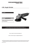
7” Angle Grinder
46237
Set up And Operating Instructions
Distributed exclusively by Harbor Freight Tools®.
3491 Mission Oaks Blvd., Camarillo, CA 93011
Visit our website at: http://www.harborfreight.com
Read this material before using this product.
Failure to do so can result in serious injury.
Save this manual.
Copyright© 2001 by Harbor Freight Tools®. All rights reserved. No portion of this manual or any artwork
contained herein may be reproduced in any shape or form without the express written consent of Harbor
Freight Tools. Diagrams within this manual may not be drawn proportionally. Due to continuing improvements,
actual product may differ slightly from the product described herein.
For technical questions or replacement parts, please call 1-800-444-3353.
Manual revised 09a
Save This Manual
NOTICE is used to
address practices
not related to personal injury.
Keep this manual for the safety warnings and precautions, assembly, operating, inspection, maintenance and cleaning
procedures. Write the product’s serial
number in the back of the manual near the
assembly diagram (or month and year of
purchase if product has no number). Keep
this manual and the receipt in a safe and
dry place for future reference.
CAUTION, without
the safety alert
symbol, is used to address
practices not related to
personal injury.
General Power Tool Safety
Warnings
Important SAFETY
Information
WARNING Read all safety
warnings and instructions.
Failure to follow the warnings and
instructions may result in electric
shock, fire and/or serious injury.
Save all warnings and
instructions for future reference.
The term ″power tool″ in the
warnings refers to your mainsoperated (corded) power tool or
battery-operated (cordless) power
tool.
In this manual, on the labeling,
and all other information provided with this product:
This is the safety alert
symbol. It is used to alert
you to potential personal
injury hazards. Obey all
safety messages that
follow this symbol to avoid
possible injury or death.
1.
a.Keep work area clean and well lit.
Cluttered or dark areas invite accidents.
DANGER indicates
a hazardous
situation which, if not
avoided, will result in death or
serious injury.
b.Do not operate power tools in
explosive atmospheres, such as in
the presence of flammable liquids,
gases or dust. Power tools create
sparks which may ignite the dust or
fumes.
WARNING
indicates a
hazardous situation which, if
not avoided, could result in
death or serious injury.
CAUTION, used
with the safety
alert symbol, indicates a
hazardous situation which, if
not avoided, could result in
minor or moderate injury.
SKU 46237
Work area safety
c.Keep children and bystanders
away while operating a power tool.
Distractions can cause you to lose
control.
2.
Electrical safety
a.Power tool plugs must match the
outlet. Never modify the plug in
any way. Do not use any adapter
For technical questions, please call 1-800-444-3353.
Page 2
plugs with grounded power tools.
Unmodified plugs and matching outlets will reduce risk of electric shock.
b.Avoid body contact with grounded
surfaces such as pipes, radiators,
ranges and refrigerators. There is
an increased risk of electric shock if
your body is grounded.
c.Do not expose power tools to rain
or wet conditions. Water entering
a power tool will increase the risk of
electric shock.
d.Do not abuse the cord. Never use
the cord for carrying, pulling or
unplugging the power tool. Keep
cord away from heat, oil, sharp
edges or moving parts. Damaged
or entangled cords increase the risk
of electric shock.
e.When operating a power tool outdoors, use an extension cord suitable for outdoor use. Use of a cord
suitable for outdoor use reduces the
risk of electric shock.
f. If operating a power tool in a damp
location is unavoidable, use a
Ground Fault Circuit Interrupter
(GFCI) protected supply. Use of
a GFCI reduces the risk of electric
shock.
3.
Personal safety
a.Stay alert, watch what you are doing and use common sense when
operating a power tool. Do not use
a power tool while you are tired
or under the influence of drugs,
alcohol or medication. A moment
of inattention while operating power
tools may result in serious personal
injury.
b.Use personal protective equipment. Always wear eye protection.
SKU 46237
Safety equipment such as dust mask,
non-skid safety shoes, hard hat, or
hearing protection used for appropriate conditions will reduce personal
injuries.
c.Prevent unintentional starting.
Ensure the switch is in the off-position before connecting to power
source and/or battery pack, picking up or carrying the tool. Carrying power tools with your finger on
the switch or energizing power tools
that have the switch on invites accidents.
d.Remove any adjusting key or
wrench before turning the power
tool on. A wrench or a key left attached to a rotating part of the power
tool may result in personal injury.
e.Do not overreach. Keep proper
footing and balance at all times.
This enables better control of the
power tool in unexpected situations.
f. Dress properly. Do not wear loose
clothing or jewelry. Keep your
hair, clothing and gloves away
from moving parts. Loose clothes,
jewelry or long hair can be caught in
moving parts.
g.If devices are provided for the connection of dust extraction and collection facilities, ensure these are
connected and properly used. Use
of these devices can reduce dustrelated hazards.
h.Only use safety equipment that
has been approved by an appropriate standards agency. Unapproved
safety equipment may not provide
adequate protection. Eye protection
must be ANSI-approved and breathing protection must be NIOSH-ap-
For technical questions, please call 1-800-444-3353.
Page 3
g.Use the power tool, accessories
and tool bits etc. in accordance
with these instructions, taking into
account the working conditions
and the work to be performed. Use
of the power tool for operations different from those intended could result
in a hazardous situation.
proved for the specific hazards in the
work area.
4.
Power tool use and care
a.Do not force the power tool. Use
the correct power tool for your application. The correct power tool will
do the job better and safer at the rate
for which it was designed.
b.Do not use the power tool if the
switch does not turn it on and off.
Any power tool that cannot be controlled with the switch is dangerous
and must be repaired.
c.Disconnect the plug from the
power source and/or the battery
pack from the power tool before
making any adjustments, changing accessories, or storing power
tools. Such preventive safety measures reduce the risk of starting the
power tool accidentally.
d.Store idle power tools out of the
reach of children and do not allow
persons unfamiliar with the power
tool or these instructions to operate the power tool. Power tools are
dangerous in the hands of untrained
users.
e.Maintain power tools. Check for
misalignment or binding of moving
parts, breakage of parts and any
other condition that may affect the
power tool’s operation. If damaged, have the power tool repaired
before use. Many accidents are
caused by poorly maintained power
tools.
f. Keep cutting tools sharp and
clean. Properly maintained cutting
tools with sharp cutting edges are
less likely to bind and are easier to
control.
SKU 46237
5.
Service
a.Have your power tool serviced by
a qualified repair person using
only identical replacement parts.
This will ensure that the safety of the
power tool is maintained.
Grinding, Sanding or Wire
Brushing Operation Safety
Warnings
1.
This power tool is intended to
function as a grinder, sander or
wire brushing tool. Read all safety
warnings, instructions, illustrations and specifications provided
with this power tool. Failure to follow all instructions listed below may
result in electric shock, fire and/or
serious injury.
2.
Operations such as polishing or
cutting-off are not recommended
to be performed with this power
tool. Operations for which the power
tool was not designed may create a
hazard and cause personal injury.
3.
Do not use accessories which
are not specifically designed and
recommended by the tool manufacturer. Just because the accessory
can be attached to your power tool, it
does not assure safe operation.
4.
The rated speed of the accessory
must be at least equal to the maxi-
For technical questions, please call 1-800-444-3353.
Page 4
mum speed marked on the power
tool. Accessories running faster than
their RATED SPEED can break and
fly apart.
sive or work piece fragments. The
eye protection must be capable of
stopping flying debris generated
by various operations. The eye protection must be capable of stopping
flying debris generated by various
operations. The dust mask or respirator must be capable of filtrating particles generated by your operation.
Prolonged exposure to high intensity
noise may cause hearing loss.
5.
The outside diameter and the
thickness of your accessory must
be within the capacity rating of
your power tool. Incorrectly sized
accessories cannot be adequately
guarded or controlled.
6.
The arbor size of wheels, flanges,
backing pads or any other accessory must properly fit the spindle
of the power tool. Accessories with
arbor holes that do not match the
mounting hardware of the power tool
will run out of balance, vibrate excessively and may cause loss of control.
9.
7.
Do not use a damaged accessory.
Before each use inspect the accessory such as abrasive wheels
for chips and cracks, backing pad
for cracks, tear or excess wear,
wire brush for loose or cracked
wires. If power tool or accessory
is dropped, inspect for damage or
install an undamaged accessory.
After inspecting and installing an
accessory, position yourself and
bystanders away from the plane of
the rotating accessory and run the
power tool at maximum no-load
speed for one minute. Damaged
accessories will normally break apart
during this test time.
10. Hold power tool by insulated gripping surfaces only, when performing an operation where the cutting
accessory may contact hidden
wiring or its own cord. Cutting accessory contacting a ″live″ wire may
make exposed metal parts of the
power tool ″live″ and shock the operator.
8.
Wear personal protective equipment. Depending on application,
use face shield, safety goggles
or safety glasses. As appropriate,
wear dust mask, hearing protectors, gloves and workshop apron
capable of stopping small abra-
SKU 46237
Keep bystanders a safe distance
away from work area. Anyone
entering the work area must wear
personal protective equipment.
Fragments of work piece or of a
broken accessory may fly away and
cause injury beyond immediate area
of operation.
11. Position the cord clear of the spinning accessory. If you lose control,
the cord may be cut or snagged and
your hand or arm may be pulled into
the spinning accessory.
12. Never lay the power tool down
until the accessory has come to a
complete stop. The spinning accessory may grab the surface and pull
the power tool out of your control.
13. Do not run the power tool while
carrying it at your side. Accidental
contact with the spinning accessory
For technical questions, please call 1-800-444-3353.
Page 5
could snag your clothing, pulling the
accessory into your body.
14. Regularly clean the power tool’s
air vents. The motor’s fan will draw
the dust inside the housing and excessive accumulation of powdered
metal may cause electrical hazards.
15. Do not operate the power tool near
flammable materials. Sparks could
ignite these materials.
16. Do not use accessories that require liquid coolants. Using water
or other liquid coolants may result in
electrocution or shock.
17. Maintain labels and nameplates on
the tool. These carry important safety
information. If unreadable or missing, contact Harbor Freight Tools for a
replacement.
18. Avoid unintentional starting. Prepare
to begin work before turning on the
tool.
19. Do not lay the tool down until it has
come to a complete stop. Moving
parts can grab the surface and pull
the tool out of your control.
20. Do not leave the tool unattended
when it is plugged into an electrical
outlet. Turn off the tool, and unplug it
from its electrical outlet before leaving.
21. This product is not a toy. Keep it out
of reach of children.
22. People with pacemakers should
consult their physician(s) before use.
Electromagnetic fields in close proximity to heart pacemaker could cause
pacemaker interference or pacemaker failure. In addition, people with
SKU 46237
pacemakers should:
• Avoid operating alone.
• Do not use with power switch locked
on.
• Properly maintain and inspect to
avoid electrical shock.
• Any power cord must be properly
grounded. Ground Fault Circuit Interrupter (GFCI) should also be implemented – it prevents sustained electrical shock.
23. Some dust created by power sanding, sawing, grinding, drilling, and
other construction activities, contains
chemicals known [to the State of California] to cause cancer, birth defects
or other reproductive harm. Some
examples of these chemicals are:
• Lead from lead-based paints
• Crystalline silica from bricks and cement or other masonry products
• Arsenic and chromium from chemically treated lumber
Your risk from these exposures varies, depending on how often you do
this type of work. To reduce your
exposure to these chemicals: work in
a well ventilated area, and work with
approved safety equipment, such as
those dust masks that are specially
designed to filter out microscopic
particles. (California Health & Safety
Code § 25249.5, et seq.)
24. WARNING: Handling the cord on
this product will expose you to lead,
a chemical known to the State of
California to cause cancer, and birth
defects or other reproductive harm.
Wash hands after handling. (California Health & Safety Code § 25249.5,
et seq.)
25. The warnings, precautions, and instructions discussed in this instruction
For technical questions, please call 1-800-444-3353.
Page 6
manual cannot cover all possible conditions and situations that may occur.
It must be understood by the operator
that common sense and caution are
factors which cannot be built into this
product, but must be supplied by the
operator.
2.
Never place your hand near the
rotating accessory. Accessory may
kickback over your hand.
3.
Do not position your body in the
area where power tool will move
if kickback occurs. Kickback will
propel the tool in direction opposite to
the wheel’s movement at the point of
snagging.
4.
Use special care when working
corners, sharp edges etc. Avoid
bouncing and snagging the accessory. Corners, sharp edges or
bouncing have a tendency to snag
the rotating accessory and cause loss
of control or kickback.
5.
Do not attach a saw chain woodcarving blade or toothed saw
blade. Such blades create frequent
kickback and loss of control.
Kickback and Related Warnings
Kickback is a sudden reaction to a
pinched or snagged rotating wheel, backing pad, brush or any other accessory.
Pinching or snagging causes rapid stalling of the rotating accessory which in turn
causes the uncontrolled power tool to be
forced in the direction opposite of the accessory’s rotation at the point of the binding.
For example, if an abrasive wheel is
snagged or pinched by the workpiece, the
edge of the wheel that is entering into the
pinch point can dig into the surface of the
material causing the wheel to climb out
or kick out. The wheel may either jump
toward or away from the operator, depending on direction of the wheel’s movement
at the point of pinching. Abrasive wheels
may also break under these conditions.
Kickback is the result of power tool
misuse and/or incorrect operating procedures or conditions and can be avoided by
taking proper precautions as given below.
1.
Maintain a firm grip on the power
tool and position your body and
arm to allow you to resist kickback forces. Always use auxiliary
handle, if provided, for maximum
control over kickback or torque
reaction during start-up. The operator can control torque reactions or
kickback forces, if proper precautions
are taken.
SKU 46237
Safety Warnings Specific for
Grinding Operations
1.
Use only wheel types that are
recommended for your power tool
and the specific guard designed
for the selected wheel. Wheels for
which the power tool was not designed cannot be adequately guarded
and are unsafe.
2.
The guard must be securely attached to the power tool and positioned for maximum safety, so the
least amount of wheel is exposed
towards the operator. The guard
helps to protect operator from broken
wheel fragments and accidental contact with wheel.
3.
Wheels must be used only for
recommended applications. For
example: do not grind with the
For technical questions, please call 1-800-444-3353.
Page 7
4.
5.
side of cut-off wheel. Abrasive cutoff wheels are intended for peripheral
grinding, side forces applied to these
wheels may cause them to shatter.
2.
Do not smoke during use. Nicotine reduces the blood supply to the
hands and fingers, increasing the risk
of vibration-related injury.
Always use undamaged wheel
flanges that are of correct size and
shape for your selected wheel.
Proper wheel flanges support the
wheel thus reducing the possibility of
wheel breakage. Flanges for cut-off
wheels may be different from grinding
wheel flanges.
3.
Wear suitable gloves to reduce the
vibration effects on the user.
4.
Use tools with the lowest vibration
when there is a choice between different processes.
5.
Include vibration-free periods each
day of work.
Do not use worn down wheels
from larger power tools. Wheel
intended for larger power tool is not
suitable for the higher speed of a
smaller tool and may burst.
6.
Grip tool as lightly as possible (while
still keeping safe control of it). Let
the tool do the work.
7.
To reduce vibration, maintain the tool
as explained in this manual. If any
abnormal vibration occurs, stop use
immediately.
Vibration Safety
This tool vibrates during use. Repeated or long-term exposure to vibration may cause temporary or permanent
physical injury, particularly to the hands,
arms and shoulders. To reduce the risk of
vibration-related injury:
1.
Save these
instructions.
Anyone using vibrating tools regularly or for an extended period should
first be examined by a doctor and
then have regular medical checkups to ensure medical problems are
not being caused or worsened from
use. Pregnant women or people
who have impaired blood circulation
to the hand, past hand injuries, nervous system disorders, diabetes, or
Raynaud’s Disease should not use
this tool. If you feel any medical or
physical symptoms related to vibration (such as tingling, numbness, and
white or blue fingers), seek medical
advice as soon as possible.
SKU 46237
For technical questions, please call 1-800-444-3353.
Page 8
of electric shock. (See 3-Prong Plug
and Outlet.)
Grounding
To prevent
electric shock
and death from
incorrect grounding
wire connection:
Check with a qualified
electrician if you are in doubt
as to whether the outlet is
properly grounded. Do not
modify the power cord plug
provided with the tool. Never
remove the grounding prong
from the plug. Do not use the
tool if the power cord or plug
is damaged. If damaged, have
it repaired by a service facility
before use. If the plug will not
fit the outlet, have a proper
outlet installed by a qualified
electrician.
2.
The grounding prong in the plug is
connected through the green wire inside the cord to the grounding system
in the tool. The green wire in the cord
must be the only wire connected to
the tool’s grounding system and must
never be attached to an electrically
“live” terminal. (See 3-Prong Plug
and Outlet.)
3.
The tool must be plugged into an
appropriate outlet, properly installed
and grounded in accordance with all
codes and ordinances. The plug and
outlet should look like those in the
preceding illustration. (See 3-Prong
Plug and Outlet.)
Double Insulated Tools: Tools
with Two Prong Plugs
Grounded Tools: Tools with Three
Prong Plugs
1.
1.
Tools marked with “Grounding Required” have a three wire cord and
three prong grounding plug. The
plug must be connected to a properly
grounded outlet. If the tool should
electrically malfunction or break
down, grounding provides a low
resistance path to carry electricity
away from the user, reducing the risk
SKU 46237
Tools marked “Double Insulated” do
not require grounding. They have
a special double insulation system
which satisfies OSHA requirements
and complies with the applicable
standards of Underwriters Laboratories, Inc., the Canadian Standard
Association, and the National Electrical Code. (See Outlets for 2-Prong
Plug.)
For technical questions, please call 1-800-444-3353.
Page 9
3.
4.
5.
6.
As the distance from the supply outlet
increases, you must use a heavier
gauge extension cord. Using extension cords with inadequately sized
wire causes a serious drop in voltage,
resulting in loss of power and possible tool damage.
(See Table A.) The smaller the
gauge number of the wire, the greater
the capacity of the cord. For example, a 14 gauge cord can carry a
higher current than a 16 gauge cord.
(See Table A.)
RECOMMENDED MINIMUM WIRE
GAUGE FOR EXTENSION CORDS*
(120/240 VOLT)
NAMEPLATE
AMPERES
(at full load)
0 – 2.0
18
18
18
18
16
2.1 – 3.4
18
18
18
16
14
3.5 – 5.0
18
18
16
14
12
5.1 – 7.0
18
16
14
12
12
7.1 – 12.0
18
14
12
10
-
12.1 – 16.0
14
12
10
-
-
16.1 – 20.0
12
10
-
-
-
TABLE A
* Based on limiting the line
voltage drop to five volts at
150% of the rated amperes.
Symbology
When using more than one extension cord to make up the total length,
make sure each cord contains at
least the minimum wire size required.
(See Table A.)
If you are using one extension cord
for more than one tool, add the
nameplate amperes and use the sum
to determine the required minimum
cord size. (See Table A.)
If you are using an extension cord
outdoors, make sure it is marked with
the suffix “W-A” (“W” in Canada) to
indicate it is acceptable for outdoor
use.
EXTENSION CORD
LENGTH
150’
2.
Grounded tools require a three wire
extension cord. Double Insulated
tools can use either a two or three
wire extension cord.
Protect the extension cords from
sharp objects, excessive heat, and
damp or wet areas.
100’
1.
7.
75’
Extension Cords
extension cord or have it repaired by
a qualified electrician before using it.
50’
Double insulated tools may be used
in either of the 120 volt outlets shown
in the preceding illustration. (See
Outlets for 2-Prong Plug.)
25’
2.
Double Insulated
Canadian Standards Association
Underwriters Laboratories, Inc.
V~
A
Volts Alternating Current
Amperes
No Load Revolutions per Minute
n0 xxxx/min. (RPM)
Make sure the extension cord is properly wired and in good electrical condition. Always replace a damaged
SKU 46237
For technical questions, please call 1-800-444-3353.
Page 10
Specifications
Electrical
Requirements
120 V~ / 1300 W Input,
780 W Output
Motor No Load Speed 8,500 RPM
Wheel Diameter
7”
Arbor Diameter
7/8”
Spindle Thread
5/8” x 11 TPI
95GA
E194601
Unpacking
When unpacking, check to make sure
that the item is intact and undamaged. If
any parts are missing or broken, please
call Harbor Freight Tools at the number
shown on the cover of this manual as soon
as possible.
refer to the Assembly Diagram near
the end of this manual.
Assembly
TO PREVENT
SERIOUS INJURY:
Do not operate this tool with
one hand only or without the
Auxiliary Handle properly
installed.
Attach the Side Handle (24) by
screwing it into the hole on the right,
left or top of the Reducer (19), depending on your preference.
Functions
This hand-held tool may be used for
grinding operations.
Instructions for
putting into use
Read the entire Important
Safety Information
section at the beginning of this
manual including all text under
subheadings therein before set
up or use of this product.
To prevent
serious injury
from accidental
operation:
Turn the Power Switch of the
tool to its “OFF” position and
unplug the tool from its
electrical outlet before
assembling or making any
adjustments to the tool.
Note: For additional information regarding
the parts listed in the following pages,
SKU 46237
For technical questions, please call 1-800-444-3353.
Page 11
• dry and clean.
• proven undamaged by inspection and by the ring-test explained
below.
Operating Instructions
Read the entire Important
Safety Information
section at the beginning of this
manual including all text under
subheadings therein before set
up or use of this product.
2.
Push the Brake Pin (22) button while
slowly turning the Outer Flange (1)
with the Spanner (50) provided until
the Brake Pin depresses fully. This
will prevent the Spindle (7) from spinning and allow you to unscrew the
Outer Flange.
3.
Remove the Outer Flange.
4.
Closely inspect the Grinding Wheel
before mounting. Perform a ring-test
on the wheel (unless wheel is smaller
than 7” or is an unusual shape) as
follows:
Tool Set Up
To prevent
serious injury
from accidental
operation:
Turn the Power Switch of the
tool to its “OFF” position and
unplug the tool from its
electrical outlet before
performing any inspection,
maintenance, or cleaning
procedures.
Do not install a circular saw
blade, a wood carving blade,
carving disc with saw chain
cutters, or a cutting-carving
disc on this tool.
Each accessory must have
the correct Arbor size and
must fit properly on the
Shoulder Bushing. Make sure
accessories are tightened
down securely.
Installing a Grinding Wheel
1.
Before installing a grinding wheel,
review the warnings on pages 4 - 8.
The Grinding Wheel MUST be:
• rated to at least 8,500 RPM.
• no larger than 7” in diameter.
• fitted with a 7/8” round arbor hole.
• a type of grinding wheel suitable for
surface grinding, not edge grinding.
SKU 46237
a.Suspend wheel using a pin or finger
through the arbor hole.
45°
Hang
Wheel
from
Pin
45°
V
E
R
T
I
C
A
L
Tap
Wheel
Here
C
E
N
T
E
R
45°
45°
b.Tap the flat side of the wheel with a
light non-metallic object, such as a
screwdriver handle, at a point 45°
from the vertical center line on each
side of the wheel and 1 – 2 inches
from the edge of the wheel (see Illustration).
For technical questions, please call 1-800-444-3353.
Page 12
c. Rotate the wheel 45 degrees and
repeat the test until the entire wheel
has been checked.
d.An undamaged wheel will give a
clear tone. If cracked, there will be a
dead sound and not a clear ring.
5.
6.
Slip the grinding wheel onto the Spindle with a paper gasket, or blotter,
first. The blotter should be centered
on the grinding wheel and the wheel
and blotter should rest flat against the
Inner Flange.
WARNING: To prevent serious
injury, blotters must be used for all
grinding wheels they are provided
with. Blotters help prevent grinding wheel damage and wheel slippage, causes of wheel failure.
Thread the Outer Flange onto the
Spindle. Wrench tighten only enough
so that the wheel is securely held on
the spindle.
WARNING: To prevent serious
injury, do not overtighten flange.
Overtightening can damage the
wheel, causing wheel failure.
allow access by children or pets to
prevent injury and distraction.
2.
Route the power cord along a safe
route to reach the work area without
creating a tripping hazard or exposing
the power cord to possible damage.
The power cord must reach the work
area with enough extra length to allow free movement while working.
3.
Secure loose work pieces using a
vise or clamps (not included) to prevent movement while working.
4.
There must not be hazardous objects, such as utility lines or foreign
objects, nearby that will present a
hazard while working.
5.
You must use personal safety equipment including, but not limited to,
ANSI-approved eye and hearing protection, as well as heavy work gloves.
6.
Before beginning work, provide for
sparks and debris that will fly off the
work surface.
Guard Adjustment
7.
Adjust the Wheel Guard so that it
provides a shield between the user
and the wheel.
8.
Loosen the Nut (4) that holds the
Guard in place, reposition the Guard
as needed to provide protection from
the wheel, and tighten the Nut again.
Do not remove the guard.
Work Piece and Work Area Set Up
1.
Designate a work area that is clean
and well-lit. The work area must not
SKU 46237
For technical questions, please call 1-800-444-3353.
Page 13
General Operating Instructions
To prevent
serious injury:
Grip the tool firmly in both
hands.
1.
Plug the Cord (41) into the electrical
outlet.
2.
Secure the material being cut. Hold
the Handle with one hand, and the
Back Handle (44) with the other, and
press down on the Switch (38). This
will start the motor.
3.
Allow the tool to come up to full
speed before touching the work material.
4.
Apply the wheel to the work material, allowing the tool to operate at
full speed. If the tool bogs down, use
lighter pressure.
5.
To lock the tool in the “On” position,
activate the Switch and push the
Switch Lock (51) button located on
the left side of the Back Handle. Now
you can continue grinding without
having to hold onto the Switch. Keep
your hand in same position in case
you need to shut off the unit in a
hurry. To turn the tool off, press down
on the Switch again.
6.
To create a smoother surface, keep
the tool moving over the work surface.
7.
Release the Trigger Switch to stop
the tool.
8.
Allow the tool to come to a complete
stop before setting it down.
9.
To prevent accidents, turn off the tool
and disconnect its power supply after
SKU 46237
use. Clean, then store the tool indoors out of children’s reach.
For technical questions, please call 1-800-444-3353.
Page 14
Maintenance And
Servicing
3.
After Use, clean external surfaces
of the tool with clean cloth. Never use
solvents or harsh cleaners as they
may damage the housing. To prevent electrical shock, do not allow
water or other liquids to enter the
motor vent holes.
4.
Carbon Brush (46) Maintenance.
The carbon brushes may require
maintenance when the motor performance of the tool decreases or stops
working completely. To maintain the
brushes:
Procedures not specifically
explained in this manual
must be performed only by a
qualified technician.
To prevent
serious injury
from accidental
operation:
Turn the Power Switch of the
tool to its “OFF” position and
unplug the tool from its
electrical outlet before
performing any inspection,
maintenance, or cleaning
procedures.
To prevent serious
injury from tool
failure:
Do not use damaged
equipment. If abnormal noise
or vibration occurs, have the
problem corrected before
further use.
Cleaning, Maintenance, and
Lubrication
1.
2.
BEFORE EACH USE, inspect the
general condition of the tool. Check
for loose screws, misalignment or
binding of moving parts, cracked or
broken parts, damaged electrical wiring, and any other condition that may
affect its safe operation.
Periodically blow dust and grit out
of the motor vents using dry compressed air. Always wear safety
glasses when performing this maintenance operation.
SKU 46237
a.Unscrew the Brush Cap (45) using
a flat head screwdriver (sold separately).
b.Pull Brush from the Plastic Housing
(35). Keep track of which orientation the old carbon brushes were
in to prevent needless wear if they
will be reinstalled.
c. If either carbon brush is worn down
by more than 1/2, replace both carbon brushes.
d.To clean old carbon brushes before
reusing them, rub the contact areas
with a pencil eraser.
e.Hold the spring clips to the side and
reinsert the old carbon brushes in
the same orientation to reduce wear.
f. When installing the carbon brushes,
make sure the carbon portions of
the carbon brushes contact the motor armature, and that the indented
portions of the brushes are positioned where the springs contact.
Also, make sure the springs operate
freely.
g.Reconnect the Carbon Brush Leads.
h.Replace the Brush Caps. Do not
overtighten.
For technical questions, please call 1-800-444-3353.
Page 15
Note: New carbon brushes tend to spark
when first used until they wear and
conform to the motor’s armature.
Problem
5.
WARNING! If the supply cord of
this power tool is damaged, it must
be replaced only by a qualified
service technician.
Troubleshooting
Possible Causes
Likely Solutions
Tool will not start
1. No power at outlet.
2. Cord not connected.
3. Carbon Brushes may be worn or
damaged.
1. Check power at outlet.
2. Check that cord is plugged in.
3. Inspect Carbon Brushes and replace if
necessary.
Tool operates
slowly or
erratically.
1. Carbon Brushes may be worn or
damaged.
2. Excess pressure applied to
workpiece.
1. Inspect Carbon Brushes and replace if
necessary.
2. Decrease pressure, allow tool to do
the work.
Tool does not grind 1. Disc accessory may be loose on
effectively.
Spindle. Check tightness of Outer
Flange Arbor Nut or threaded disc
accessory on Spindle.
2. Disc accessory may be damaged,
worn or wrong type for the
material.
1. Be sure disc accessory is of correct
dimension and Outer Flange Arbor Nut
is tight.
2. Check condition and type of disc
accessory. Use only proper type of
disc accessory in good condition.
Follow all safety precautions whenever diagnosing or servicing the
tool. Disconnect power supply before service.
SKU 46237
For technical questions, please call 1-800-444-3353.
Page 16
Parts List
PLEASE READ THE FOLLOWING CAREFULLY
The manufacturer and/or distributor has provided the parts list and assembly
diagram in this manual as a reference tool only. Neither the manufacturer or
distributor makes any representation or warranty of any kind to the buyer that
he or she is qualified to make any repairs to the product, or that he or she is
qualified to replace any parts of the product. In fact, the manufacturer and/
or distributor expressly states that all repairs and parts replacements should
be undertaken by certified and licensed technicians, and not by the buyer. The
buyer assumes all risk and liability arising out of his or her repairs to the
original product or replacement parts thereto, or arising out of his or her
installation of replacement parts thereto.
SKU 46237
For technical questions, please call 1-800-444-3353.
Page 17
ASSEMBLY DIAGRAM
Record Product’s Serial Number Here:
Note: If product has no serial number, record month and year of purchase instead.
Note: Some parts are listed and shown for illustration purposes only, and are not available individually as replacement parts.
SKU 46237
For technical questions, please call 1-800-444-3353.
Page 18
LIMITED 90 DAY WARRANTY
Harbor Freight Tools Co. makes every effort to assure that its products meet high
quality and durability standards, and warrants to the original purchaser that this product is free from defects in materials and workmanship for the period of 90 days from
the date of purchase. This warranty does not apply to damage due directly or indirectly,
to misuse, abuse, negligence or accidents, repairs or alterations outside our facilities,
criminal activity, improper installation, normal wear and tear, or to lack of maintenance.
We shall in no event be liable for death, injuries to persons or property, or for incidental,
contingent, special or consequential damages arising from the use of our product. Some
states do not allow the exclusion or limitation of incidental or consequential damages, so
the above limitation of exclusion may not apply to you. This warranty is expressly in lieu of all other warranties, express or implied, including the
warranties of merchantability and fitness.
To take advantage of this warranty, the product or part must be returned to us with
transportation charges prepaid. Proof of purchase date and an explanation of the complaint must accompany the merchandise. If our inspection verifies the defect, we will either repair or replace the product at our election or we may elect to refund the purchase
price if we cannot readily and quickly provide you with a replacement. We will return repaired products at our expense, but if we determine there is no defect, or that the defect
resulted from causes not within the scope of our warranty, then you must bear the cost
of returning the product.
This warranty gives you specific legal rights and you may also have other rights
which vary from state to state.
3491 Mission Oaks Blvd. • PO Box 6009 • Camarillo, CA 93011 • (800) 444-3353
SKU 46237
For technical questions, please call 1-800-444-3353.
Page 19