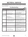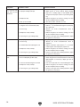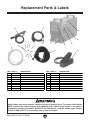
1
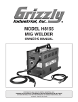
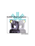
MODEL H8154
AC/DC STICK/TIG WELDER
OWNER'S MANUAL
COPYRIGHT © MAY, 2007 BY GRIZZLY INDUSTRIAL, INC.
WARNING: NO PORTION OF THIS MANUAL MAY BE REPRODUCED IN ANY SHAPE
OR FORM WITHOUT THE WRITTEN APPROVAL OF GRIZZLY INDUSTRIAL, INC.
#TS9402 PRINTED IN CHINA
�����������������������������������������������������������������������
��������������������������������������������������������������
����������������������������������������������������������������������
��������������������������������������������������������������������
������������������������
������������������������������������������������������������������
��������������������������������������������������������������������
�����������������������������������������������������������������
����������������������������������������������������������������������
���������������������������������������������������������������������
�����������������������������������������������������
�����������������������������������������������������������������������
��������������������������������������������������������������������
�����������������������������������������������������������������������
������������������������������������������������������������������
�������������������������������������������������������������������
��������������������
�� �������������������������������������
�� ����������������������������
������������������������������������������������������������������
������������������������������������������������������������������
��������������������������������������������������������������������
����������������������������������������������������������������������
������������������������������������
Table of Contents
INTRODUCTION ............................................................................................................................... 2
Foreword .................................................................................................................................... 2
Contact Info ................................................................................................................................ 2
Specifications ............................................................................................................................. 3
Identification ............................................................................................................................... 3
SECTION 1: SAFETY ....................................................................................................................... 4
Safety Instructions for Stick/TIG Welders .................................................................................. 4
Additional Sources for Welding Codes and Standards .............................................................. 6
SECTION 2: CIRCUIT REQUIREMENTS ........................................................................................ 7
220V Operation .......................................................................................................................... 7
Grounding for Welding Safety .................................................................................................... 8
SECTION 3: INVENTORY ................................................................................................................ 9
SECTION 4: OPERATIONS ........................................................................................................... 10
Operation Safety ...................................................................................................................... 10
Welder Duty Cycle ................................................................................................................... 10
Welder Controls ....................................................................................................................... 11
General Welding Operations .................................................................................................... 13
SECTION 5: ACCESSORIES ......................................................................................................... 14
SECTION 6: SERVICE ................................................................................................................... 15
Troubleshooting........................................................................................................................ 15
Replacement Parts & Labels ................................................................................................... 17
WARRANTY AND RETURNS ........................................................................................................ 21
INTRODUCTION
Foreword
Contact Info
We are proud to offer the Model H8154 AC/DC
Stick/TIG Welder. This machine is part of a growing Grizzly family of fine metalworking equipment.
When used according to the guidelines set forth in
this manual, you can expect years of trouble-free,
enjoyable operation and proof of Grizzly’s commitment to customer satisfaction.
If you have any comments regarding this manual,
please write to us at the address below:
The specifications, drawings, and photographs
illustrated in this manual represent the Model
H8154 when the manual was prepared. However,
owing to Grizzly’s policy of continuous improvement, changes may be made at any time with no
obligation on the part of Grizzly.
For your convenience, we always keep current
Grizzly manuals available on our website at www.
grizzly.com. Any updates to your machine will be
reflected in these manuals as soon as they are
complete. Visit our site often to check for the latest updates to this manual!
-2-
Grizzly Industrial, Inc.
/O Technical Documentation Manager
P.O. Box 2069
Bellingham, WA 98227-2069
Email: [email protected]
C
We stand behind our machines. If you have any
service questions or parts requests, please call or
write us at the location listed below.
Grizzly Industrial, Inc.
1203 Lycoming Mall Circle
Muncy, PA 17756
Phone: (570) 546-9663
Fax: (800) 438-5901
E-Mail: [email protected]
Web Site: http://www.grizzly.com
H8154 AC/DC Stick/TIG Welder
Specifications
Stick Welding Current..............................5–130A
Stick Duty Cycle .............................35% @ 130A
AC TIG Welding Current .......................20–160A
AC TIG Duty Cycle .........................35% @ 160A
AC TIG Square Wave Balance .............. 30–70%
AC TIG Square Wave Frequency ........20-100Hz
DC TIG Welding Current .........................5–160A
DC TIG Duty Cycle .........................35% @ 160A
DC TIG Current Upslope .........................0.2 sec.
DC TIG Current Downslope ................. 1-10 sec.
TIG Gas Pre-Flow ................................0–10 sec.
TIG Gas Post-Flow ...............................1–25 sec.
Power Consumption ................23.8A @ 220VAC
Output Power .....................................60–80VDC
Length/Width/Height ..................... 21 x 9 x 16 in.
Net Weight .................................................22 lbs.
M
L
O
Figure 2. Model H8154 front connections.
L.
M.
N.
O.
Positive Output Socket
Negative Output Socket
Remote Control Connection
Gas Outlet Connection
Identification
D
A
B
N
P
T
E
C
S
F
Q
R
Figure 3. Model H8154 features on back of
welder.
K
J
I
H
G
Figure 1. Model H8154 control panel.
A.
B.
C.
D.
E.
F.
G.
H.
I.
J.
K.
Output Current Dial
Square Wave Balance Dial
Downslope Current Dial
Power Light
Warning Light
Post-Flow Time Dial
Welding Current LED Readout
Stick/TIG Selector
2-Step/4-Step Selector
AC/DC Selector
Pre-Flow Time Dial
H8154 AC/DC Stick/TIG Welder
P.
Q.
R.
S.
T.
Power ON/OFF Switch
Gas Inlet Connection
Power Cord
Welder Enclosure Ground Terminal
Cooling Fan and Cover
-3-
�����������������
��������������������������������������
������������������������������������
��������������������������������������������������������������������������������������������������
��������������������������������������������������������������������������������������������
��������������������������������������������������������������������������������������������
��������������������������������������������������������������������������������������������
��������������������
�������������������������������������������������������������������
���������������������������������������
�������������������������������������������������������������������
����������������������������������������
�������������������������������������������������������������������
���������������������������������������������������������������������
�������������������������
������
������������������������������������������������������������������
��������������������������������
���������������������������������
Safety Instructions for
Stick/TIG Welders
��� ������� ���� �������� �����������
���� �������������������������������
1.
�����������������������������������
����� ��������
������� ��������
����������
READ
THIS MANUAL.
This ���
manual
con�������
tains proper operating and safety proce-
dures for this equipment.
��� ������� ���� ����� ���������
�������������������������������
2. WELDING FUMES. Breathing welding
����������� ��������� ����������� �����
fumes can cause suffocation or poisoning
����� ������� ���������� ������������ ����
without warning. Keep your head out of
�������������������
welding fumes. Use adequate ventilation
at the arc to
safely��
remove
the
fumes from
��� �������
�����
������
���������
your
breathing
zone
and
the
general
area.
����������� ����� ����������
Use
ANSI
approved
respirators
for
the
type
���������� ����� ��������� ������
of
welding
operation.
Protect
others
from
����� ����� ���� ������ ������� ������������
these fumes.
����������
-4-
3.
����� ���������� �����������
����������
������
���� ������
����������
WELDING IN
A CONFINED
SPACE
CAN
��������������
BE
HAZARDOUS. Always open all covers,
sustain forced ventilation, remove toxic and
��� ����� ������� ��������� ��� ����
hazardous
materials, and provide a power
����������������������������������������������
disconnect
to the
inside
the�������
work
��� �������� �����
����welder
������ ���
�������
space.
Always
work
with
someone
who
����� ����������� ����� ��������� ��� ��������
can
give
you
help
from
outside
the
space.
�������������������������������������
Welding can displace oxygen. Always check
safe breathing
atmosphere
and provide
��� for
������
��������
����������
�����
air-supplied
respirators if necessary. Keep
��������������������������������
in
mind that all normal welding hazards are
������������������������������������
intensified
in a confined space.
������������������������������������
H8154 AC/DC Stick/TIG Welder
4.
ELECTRIC SHOCK. DO NOT touch live
electrical parts. Connect welder to power
source with approved earth ground. Make
sure all electrical connections are tight,
clean, and dry. Connect workpiece to
approved earth ground. The work lead is
NOT a ground connection and is to be
used only to complete the working welding
circuit.
5.
PREVENT FIRES. Welding work zones
must be kept clear of flammable liquids,
such as gasoline and solvents; combustible solids, such as paper and wood; and
flammable gases, such as acetylene and
hydrogen. Provide approved fire barriers
and fire extinguishing equipment for the
welding zone. Stay alert for sparks and
spatter thrown into cracks and crevices that
can start a smoldering fire.
6.
7.
8.
PERSONAL PROTECTIVE EQUIPMENT.
Wear eye, ear, and body protection
approved for welding operations. Wear
complete body protection, such as clean
and oil-free protective clothing, leather
gloves, protective cap, heavy long-sleeve
shirt, cuffless pants, and high leather boots.
DO NOT wear jewelry or frayed clothing.
Use a welding helmet with correct shade of
filter for the operation. Protect other people
and property in your working zone from
exposure to arc radiation, sparks, and spatter.
WORKING AREA. Keep working area clear
of any material not involved in the welding
operation. Keep all equipment, workpieces,
and work surfaces clean, dry, and free of
entanglements. Keep lead cables organized and away from your body.
AVOID EXPLOSION HAZARD. Never
weld on closed containers or containers
with fumes inside. Containers should be
prepared per American Welding Society
Publication F4.1, Section 7.
H8154 AC/DC Stick/TIG Welder
9.
HANDLING GAS CYLINDERS. Regardless
of content, pressurized gas cylinders can
explode. Always secure a protector cap in
place over the outlet valve assembly when
moving the cylinder. A broken off valve
could release the pressurized contents and
cause the cylinder to be hurled about at
dangerously high speeds, causing serious
property damage, personal injury, or death.
Always use safe methods when moving gas
cylinders. Always secure a gas cylinder to a
wall or approved cylinder cart with a chain
before using or storing.
10. PROTECT GAS CYLINDERS FROM HEAT
OR DAMAGE. An excess of heat can
cause the pressurized gas to expand and
explode the cylinder. Never weld on the
gas cylinder. Damaging the outside of the
cylinder can cause the cylinder to crack and
explode. Exploding pressurized gas cylinders can cause serious property damage,
personal injury, or death.
11. ELECTRIC AND MAGNETIC FIELDS
(EMF). Welding operations create EMF
around the welding equipment and
workpieces. Workers who have pacemakers must consult with their physician before
using this equipment or being within 50 feet
of welding operations.
12. EQUIPMENT MAINTENANCE. Make sure
equipment inspections and maintenance
are performed by a qualified person as
required. Stop the welding operation and
disconnect the welder from power if the
equipment is damaged or malfunctions.
13. EXPERIENCING DIFFICULTIES. If you
are experiencing difficulties performing the
intended operation, stop using the equipment. Contact our Technical Support
Department at (570) 546-9663.
-5-
Additional Sources
Additional Sources for
Welding Codes and Standards
American Welding Society, 550 N.W. LeJeune Road, Miami, FL 33126, (305) 443-9353, Website: www.
aws.org.
—Safety in welding, Cutting, and Allied Processes, ANSI Standard Z49.1
—Recommended Safe Practices for the Preparation for Welding and Cutting of Containers and Piping,
AWS F4.1
National Fire Protection Association, P. O. Box 9101, 1 Battery March Park, Quincy, MA 02269-9101, (617)
770-3000, Website: www.nfpa.org and www.sparky.org.
—National Electrical Code, NFPA Standard 70
—Standard for Fire Prevention During Welding, Cutting, and Other Hot Work, NFPA Standard 51B
Compressed Gas Association, 1735 Jefferson Davis Highway, Suite 1004, Arlington, VA 22202-4102, (703)
412-0900, Website: www.cganet.com.
—Safe Handling of Compressed Gases in Cylinders, CGA Pamphlet P-1
Canadian Standards Association, Standards Sales, 178 Rexdale Boulevard, Rexdale, Ontario, Canada
M9W 1R3, (800) 463-6727, Website: www.csa-international.org.
—Code for Safety in Welding and Cutting, CSA Standard W117.2
American National Standards Institute (ANSI), 11 West 42nd Street, New York, NY 10036-8002, (212) 6424900, Website: www.ansi.org.
—Practice for Occupational and Educational Eye and Face Protection, ANSI Standard Z87.1
U. S. Government Printing Office, Superintendent of Documents, P. O. Box 371954, Pittsburgh, PA 15250
(312) 353-2220, Website: www.osha.gov.
—OSHA, Occupational Safety and Health Standards for General Industry, Title 29, Code of Federal
Regulations (CFR), Part 1910, Subpart Q, and Part 1929, Subpart J
American Conference of Government Industrial Hygienists (ACGIH), 1330 Kemper Meadow Drive, Suite
600, Cincinnati, OH 45240-1634, (513) 742-2020, Website: www.acgih.org.
—Threshold Limit Values (Booklet)
Like all equipment there is potential danger
when operating this welder. Accidents are
frequently caused by lack of familiarity or
failure to pay attention. Use this welder with
respect and caution to lessen the possibility
of operator injury. If normal safety precautions are overlooked or ignored, serious
personal injury may occur.
-6-
No list of safety guidelines can be complete.
Every shop environment is different. Always
consider safety first, as it applies to your
individual working conditions. Use this and
other equipment with caution and respect.
Failure to do so could result in serious personal injury, damage to equipment, or poor
work results.
H8154 AC/DC Stick/TIG Welder
Circuit Requirements
SECTION 2: CIRCUIT REQUIREMENTS
220V Operation
Serious personal injury could occur if you
connect the machine to the power source
before you have completed the set up process. DO NOT connect the machine to the
power source until instructed to do so.
Grounding
In the event of an electrical short, grounding
reduces the risk of electric shock. The grounding
wire in the power cord must be properly connected
to the grounding prong on the plug; likewise, the
outlet must be properly installed and grounded.
All electrical connections must be made in accordance with local codes and ordinances.
Electrocution or fire could
result if this machine is
not grounded correctly
or if your electrical configuration does not comply with local and state
codes. Ensure compliance
by checking with a qualified electrician!
Amperage Draw
The Model H8154 welder draws the following
amps under maximum load:
Draw at 220V, Single Phase ............... 23.8 Amps
Circuit Requirements
Connect your welder to a dedicated and grounded
circuit that is rated for the amperage given below.
Never replace a circuit breaker on an existing circuit with one of higher amperage without consulting a qualified electrician to ensure compliance
with wiring codes. If you are unsure about the
wiring codes in your area or you plan to connect your machine to a shared circuit, consult
a qualified electrician.
Minimum 220V Circuit Requirement ..... 30 Amps
Plug/Receptacle Type
Recommended Plug/Receptacle....NEMA L6-30
Extension Cords
We do not recommend the use of extension cords.
Instead, arrange the placement of your equipment
and the installed wiring to eliminate the need for
extension cords.
If you find it absolutely necessary to use an extension cord at 220V with your machine:
•
Use at least a 10 gauge cord that does not
exceed 50 feet in length.
•
The extension cord must also contain a
ground wire and plug pin.
•
A qualified electrician MUST size cords over
50 feet long to prevent damage to the welder.
Figure 4. NEMA L6-30 plug and receptacle.
H8154 AC/DC Stick/TIG Welder
-7-
Grounding for
Welding Safety
There are two or more electrical circuits involved
in any welding operation. The practice of safely
grounding these circuits is documented in various codes and standards (refer to Additional
Sources for Welding Codes and Standards on
Page 6).
Welding Machine Ground
When properly connected to a power source, the
Model H8154 welder is grounded through the
power cord and local power grid. The internal
welding circuit of the welder is insulated from the
external enclosure. However, to avoid shocking
hazards if this internal insulation fails, you must
establish a separate earth ground for the welder's
external enclosure. This ground will ensure that
if a short does occur and the metal enclosure
becomes integrated with the welding current, the
current will safely dissipate directly through the
ground instead of through you.
Note: Refer to the publication NFPA 70, National
Electric Code, Article 250, Grounding, and your
local electrical codes for the correct method of
establishing this ground.
The grounding terminal for the H8154 external
enclosure is located on the left rear of the welder
(see Figure 5).
Figure 5. Location of external enclosure
grounding terminal on the rear of the Model
H8154.
-8-
Workpiece Ground
The incoming power circuit to the welder and the
working welding circuit are two separate circuits
that must have separate grounds. The welding circuit consists of the internal components
of the welder, the welding cables, the electrode
holder/torch assembly, the work clamp, and the
workpiece.
ANSI Welding Standards (Z49.1, 11.3.2.1) specify
that "Grounding [of the workpiece] shall be done
by locating the work on a grounded metal floor or
platen, or by connection to a grounded building
frame or other satisfactory ground."
Always ensure that the ground for the incoming power circuit to the welder and the
ground for the working welding circuit are
never connected. Failure to comply with this
warning could result in death, serious personal injury, or property damage.
You must also avoid "double grounding" the
workpiece. ANSI Z49.1 states that "Care shall be
taken to avoid the flow of welding current through
a connection intended only for safety grounding
since the welding current may be of a higher magnitude than the grounding conductor can safely
carry."
Note: The work lead from the welder is sometimes incorrectly referred to as the "ground lead."
The work lead from the welder is NOT a ground.
The work lead and the ground connection to the
workpiece are separate and must NOT be connected in any way.
TIG welders use a high frequency current
that creates a high electro-magnetic field
(EMF) around the welder. EMF disrupts electronic devices. To avoid damage, keep electronic devices at least 50 feet from the
welder when it is powered on. Workers who
have pacemakers must consult with their
physician before using this equipment or
being within 50 feet of welding operations.
H8154 AC/DC Stick/TIG Welder
SECTION 3: INVENTORY
The Model H8154 was carefully packed when it left our warehouse. If you discover the machine is damaged
or a part is missing after you have signed for delivery, please immediately call Customer Service at (570)
546-9663 for advice.
Save the containers and all packing materials for possible inspection by the carrier or its agent. Otherwise,
filing a freight claim can be difficult.
When you are completely satisfied with the condition of your shipment, inventory the contents.
B
A
C
F
K
E
D
J
G
H
I
Figure 6. Model H8154 inventory.
A.
B.
C.
D.
E.
F.
Model H8154 AC/DC Stick/TIG Welder
Gas Nozzles (#4, #5, and #6)
Collets (1.6, 1.8, and 2.0mm)
Collet Body
Small Collet Backcap
Long Collet Backcap
H8154 AC/DC Stick/TIG Welder
G.
H.
I.
J.
Work Clamp and Cable
Stick Electrode Clamp and Cable
Gas Tubing (Inlet)
TIG Torch Assembly, Cable, Gas Tubing,
and Torch Remote Control
K. Foot Remote Control
-9-
SECTION 4: OPERATIONS
Operation Safety
Damage to your eyes and lungs could result
from using this machine without proper
protective gear. Always wear safety glasses,
welder's helmet, and a respirator when operating this welder.
NOTICE
If you have never used this type of machine
or equipment before, WE STRONGLY RECOMMEND that you read books, trade magazines, or get formal training before beginning any projects. Regardless of the content in this section, Grizzly Industrial will
not be held liable for accidents caused by
lack of training.
Welder Duty Cycle
As the welder produces the desired power output
for the welding operation, some of the power is
converted to heat. In order to protect the welder
components from over-heating, each welder has
an established duty cycle. The duty cycle is variable depending upon the amperage output being
used.
-10-
A duty cycle is the number of minutes out of 10
minutes that the welder can safely operate at the
current amperage output without over-heating.
For instance, the Model H8154 has a stick duty
cycle of 35% at 130A output. This means that the
welder can operate continuously for 3.5 minutes
at 130A output, then the arc must be stopped for
at least 6.5 minutes to allow the welder to cool
off before starting the arc again. It is important to
leave the main power to the welder ON so that the
cooling fan can speed the cooling process.
The Model H8154 operates with an efficient cooling fan (at the rear of the welder) and has an
internal thermostat that will shut the welder down
if the maximum duty cycle has been reached.
Shutdown will be evident by the loss of welding
circuit and the illumination of the yellow warning
light on the face of the welder. When the welder
has cooled sufficiently, the internal thermostat
will re-establish the welding circuit and the yellow
warning light will go out.
Note: Most electrodes used with stick welding are
consumed within a few minutes, so the welder
has a chance to cool down when the welding circuit is stopped to install a new electrode.
However, with TIG welding, the operator needs to
plan his work within the duty cycle constraints of
the welder.
Always treat the welding components as if
they carry live welding current, even when
the welder reaches the duty cycle limit and
shuts down. When the welder re-establishes
the welding current, the electrode and work
leads will immediately carry live welding current. Ignoring this warning could result in
death or serious personal injury.
H8154 AC/DC Stick/TIG Welder
Welder Controls
D
A
B
NOTICE
After completing the welding operation,
keep the power to the welder ON for a
period of time to let the welder fan cool
the welder down. To avoid damage to your
welder, never shut the power OFF before
the welder enclosure is completely cool to
the touch.
E
C
F
E.
Warning Light:
—Not Lit: The welder is ready for use.
Figure 7. Model H8154 controls.
—Yellow: When the duty cycle has been
exceeded, the internal thermostat will disable the welding circuit until the fan has
sufficiently cooled the welder.
A. Output Current Dial: Adjust this control for
the correct welding output current.
—Green: Output current is too high or the
welder has failed.
K
J
I
H
G
—Red: Input current is incorrect.
—AC/DC Stick Welding ....................5–130A
—AC TIG Welding ..........................20–160A
—DC TIG Welding ...........................5–160A
B. Square Wave Percentage: Use this dial to
adjust the deposition and penetration of the
AC TIG arc. The dial is incremented in percentage of the positive square wave cycle.
For example, when the dial is set at 60%,
40% of each current cycle is negative and
60% is positive.
F.
Post-Flow Time Dial: This knob will control
the amount of time (0–25 seconds) gas will
flow through the TIG torch after the welding
arc is shut off.
G. Welding Current: This LED readout shows
the welding output current in amperes.
H. Stick/TIG Selector: Use this switch to select
stick or TIG welding.
C. Downslope Current Dial: Use this dial to
control the amount of time (0–10 seconds) the
welding current decreases from the selected
output current to OFF.
D. Power Light: This will light when the power
is turned ON.
H8154 AC/DC Stick/TIG Welder
-11-
I.
4. Release the torch thumb switch at any
time to raise the welding current to the
selected output current over the preset
upslope time of 0.2 seconds.
2-Step/4-Step Selector (TIG only): Select
either the 2-step or 4-step sequence for TIG
welding.
Note: The foot remote control can be substituted for the torch thumb switch in these
steps.
5. Press the thumb switch again to end the
welding operation.
—2-Step
6. The welding current decreases to the preset finish current, and stays at the level
while the thumb switch is depressed.
1. To start the sequence, press and hold
the torch thumb switch.
7. Release the thumb switch at any time to
shut off the welding current.
2. Gas flows for 0.5 seconds to purge the
torch line of air.
3. The welding current starts with a preset
upslope time of 0.2 seconds from the preset starting current of 15A to the selected
output current
4. Release the thumb switch to end the
welding sequence.
5. The welding current decreases from the
selected output current to the preset finish current over the preset downslope
time, then the welding current shuts off.
8. The shielding gas continues to flow for
the post-flow time selected.
J.
AC/DC Selector: Use this switch to select
AC or DC current output.
K. Pre-Flow Time Dial: This knob will control
the amount of time (0–10 seconds) gas will
flow through the TIG torch before the welding
current in turned on.
6. The shielding gas continues to flow for
the post-flow time selected.
—4-Step
1. To start the sequence, press the torch
thumb switch.
2. The welding current starts at the preset
starting current of 15 amps, and stays at
that level while the torch thumb switch is
depressed.
3. Gas flows for 0.5 seconds to purge the
torch line of air.
-12-
H8154 AC/DC Stick/TIG Welder
General Welding
Operations
6.
Decide which type of weld is correct for your
project and properly prepare the metal.
7.
Select the correct settings on the front control
panel for your welding operation.
Becoming a good welder takes a lot of practice
and experience. If you are a novice, read books
and get help from an experienced welder before
beginning a welding operation.
8.
Make sure all connections, hoses, gas cylinder, and grounds are correct and secure.
Note: Insert the welding cable connectors
into the welder output sockets and twist
clockwise until fully secure. For TIG welding, connect the additional remote connector
(torch or foot) and gas hose to the appropriate connections.
Practice on scrap metal and expect to spend considerable time learning the many aspects of good
welding.
Although it is beyond the scope of this manual to
instruct how to weld, here are some general steps
for successful welding:
1.
2.
Read and understand this manual and ensure
that all safety instructions are followed.
Establish a safe and efficient welding environment and ensure that you are properly
protected for the welding operation. Ensure
that there is a working fire extinguisher readily available.
3.
Have an experienced welder stand by to
assist if needed.
4.
Select the correct electrode, tungsten rod,
and filler metal type and size for your welding
project.
5.
Choose the correct amperage output and be
aware of the duty cycle for this amperage.
H8154 AC/DC Stick/TIG Welder
9.
Stay aware of the work environment around
you as you weld, and ensure that flying
sparks do not start a fire.
10. Look slightly ahead of the arc. Even with
the protection of the welder's hood, looking
directly at the arc can damage your eyes.
11 . Listen to the sound of the weld. Each type
of weld has its own distinct sound when it is
progressing correctly.
12. During at least one hour after the welding
operation is complete, check for smoldering
material or fire.
-13-
ACCESSORIES
SECTION 5: ACCESSORIES
H7786—Auto Darkening Welding Helmet
Automatic UV and IR filters protect eyes from
harmful visible and invisible light during welding.
Switching time is less than or equal to 2 milliseconds, so there's no need to flip the helmet up to
see your work under normal light conditions. Full
face protection features adjustable head suspension and adjustable delay time, sensitivity and
dark shade protection. Viewing area is 31⁄ 2" x 11⁄ 2".
Includes 2 AAA batteries.
Figure 8. Model H7786 welding helmet.
G7868—Welding Respirators
Flame retardant outer shell is recommended for
welding applications. Special depth filter provides high loading capacity for metal fumes without increasing breathing resistance. Heavy-duty
adjustable headstrap and soft, closed cell foam
face seal offers maximum comfort, protection and
fit. 5 pack.
Figure 9. Model G7868 welding respirators.
-14-
H9745—Leather Shoe Covers
H9746—Leather Knee Pads
H9748—Leather Jacket Medium (40–42)
H9887—Leather Jacket Large (44–46)
H9888—Leather Jacket X-Large (48–52)
These leather jackets, knee pads, and shoe covers provide full protection from welding sparks
and spatter. Gloves not included.
Figure 10. Models H9748/H9746/H9745 leather
welding protection.
H3157—Deluxe Welding Gloves
Top grain, leather gloves protect against welding
hazards. Extra long to protect wrists and forearms. One size fits all.
Figure 11. Model H3157 deluxe welding gloves.
H8154 AC/DC Stick/TIG Welder
Troubleshooting
SECTION 6: SERVICE
Review the troubleshooting and procedures in this section to fix or adjust your machine if a problem develops. If you need replacement parts or you are unsure of your repair skills, then feel free to call our Technical
Support at (570) 546-9663.
Troubleshooting
Symptom
Possible Cause
Possible Solution
Welder does not 1. Plug/receptacle is at fault or wired incor- 1. Test for good contacts; correct the wiring.
power up or the
rectly.
breaker trips.
2. Wiring is open/has high resistance.
2. Check for broken wires or disconnected/corroded
connections, and repair/replace as necessary.
3. ON/OFF switch is at fault.
3. Replace faulty ON/OFF switch.
4. Duty cycle has been exceeded.
4. Let the fan cool the welder.
Porosity (small cavi- 1. Arc length is too long.
ties or holes caused 2. Workpiece is dirty or damp.
from gas pockets
in weld); poor weld
bead color.
3. Damp electrodes.
4. Inadequate gas flow (TIG).
5. Incorrect electrode/filler metal used.
6. Loose fittings in torch/gas hoses (TIG).
1. Reduce length of arc.
2. Remove all grease, oil, moisture, coatings, rust, and
dirt from workpiece before welding; blow out all air
and moisture from gas lines.
3. Use dry electrodes.
4. Adjust gas flow rate as necessary.
5. Use correct type and size of electrode/filler metal.
6. Tighten torch/gas hose fittings; check gas hoses and
connections for leaks; replace if necessary.
Excessive spatter.
1.
2.
3.
4.
1.
2.
3.
4.
Amperage too high for electrode.
Voltage too high; arc length too long.
Incorrect electrode/tungsten rod used.
Incorrect gas or gas settings (TIG).
Select large electrode or decrease amperage.
Reduce voltage or arc length.
Use correct type and size of electrode/tungsten rod.
Use the correct gas for the welding operation; adjust
the gas flow as necessary.
Distortion of base 1. Excessive heat applied to base metal.
metal.
1. Make tack welds along joint before starting operation; select lower amperage for electrode; increase
travel speed; weld in small segments and allow cooling between welds.
Burn through or 1. Excessive heat applied to base metal.
excessive penetration of base metal.
1. Select lower amperage; use smaller electrode;
increase and/or maintain steady travel speed.
Lack of penetration.
1. Material too thick; joint preparation must provide
access to bottom of groove.
2. Keep arc on leading edge of weld puddle; reduce
travel speed.
3. Increase amperage; select larger electrode.
4. Use the correct gas for the welding operation; adjust
the gas flow as necessary.
1. Improper joint preparation.
2. Improper weld technique.
3. Insufficient heat applied to weld.
4. Incorrect gas or gas settings (TIG).
H8154 AC/DC Stick/TIG Welder
-15-
Symptom
Possible Cause
Failure of weld to 1. Insufficient heat applied to weld.
fuse completely with 2. Improper welding technique.
base metal or prior
weld bead.
3. Workpiece dirty.
4. Duty cycle exceeded.
Unstable arc.
1. Weld circuit polarity is incorrect.
2. Tungsten rod is contaminated (TIG).
3. Arc too long.
4. Workpiece is dirty or damp.
5. Incorrect gas or gas settings (TIG).
Arc wanders.
1. Improper gas flow (TIG).
2. Arc too long.
3. Contaminated electrode/tungsten rod.
4. Workpiece is dirty or damp.
5. Incorrect gas or gas settings (TIG).
Arc is difficult to 1. Weld circuit not complete.
start.
2. No or inadequate gas flow (TIG).
3. Incorrect electrode/tungsten rod used.
4. Workpiece is dirty or damp.
5. Incorrect gas or gas settings (TIG).
-16-
Possible Solution
1. Increase amperage; select larger electrode.
2. Widen groove to access bottom during welding;
keep arc on leading edge of weld puddle; place
stringer bead in proper location at joint during welding.
3. Remove all grease, oil, moisture, coatings, rust, and
dirt from workpiece before welding.
4. Shut down welder and allow it to cool.
1. Switch cable polarity at welder.
2. Remove 1⁄2" of contaminated tungsten rod and properly repoint rod.
3. Shorten arc; lower torch/electrode closer to
workpiece.
4. Remove all grease, oil, moisture, coatings, rust, and
dirt from workpiece before welding.
5. Use the correct gas for the welding operation; adjust
the gas flow as necessary.
1. Adjust gas flow as necessary.
2. Shorten arc; lower torch/electrode closer to
workpiece.
3. Replace electrode; (TIG) Remove 1⁄2" of contaminated tungsten rod and properly repoint rod.
4. Remove all grease, oil, moisture, coatings, rust, and
dirt from workpiece before welding.
5. Use the correct gas for the welding operation; adjust
the gas flow as necessary.
1. Check clamps and cables; tighten all connections.
2. Check all gas hoses and connections for leaks and
tighten/replace as necessary; adjust gas flow as
necessary.
3. Use correct type and size of electrode/tungsten rod.
4. Remove all grease, oil, moisture, coatings, rust, and
dirt from workpiece before welding.
5. Use the correct gas for the welding operation; adjust
the gas flow as necessary.
H8154 AC/DC Stick/TIG Welder
Replacement Parts & Labels
12
13
17
18
3
1
4
5
15
2
6
11
7
8
9
16
14
10
REF PART #
DESCRIPTION
REF PART #
DESCRIPTION
1
2
3
4
5
6
7
8
9
GAS INLET TUBE
COLLET BODY
GAS NOZZLE #4
GAS NOZZLE #5
GAS NOZZLE #6
LONG COLLET BACKCAP
SMALL COLLET BACKCAP
COLLET 1.6MM
COLLET 1.8MM
10
11
12
13
14
15
16
17
18
COLLET 2MM
TIG TORCH & CABLE ASSEMBLY
WORK CLAMP & CABLE
ELECTRODE CLAMP & CABLE
FOOT REMOTE CONTROL
ELECTRICITY LABEL
READ MANUAL LABEL
WELDER ID LABEL
SHOCK WARNING LABEL
PH8154001
PH8154002
PH8154003
PH8154004
PH8154005
PH8154006
PH8154007
PH8154008
PH8154009
PH8154010
PH8154011
PH8154012
PH8154013
PH8154014
PLABEL-14
PLABEL-12
PH8154017
PH8154018
Safety labels warn about machine hazards and ways to prevent injury. The owner of this welder
MUST maintain the original location and readability of the labels on the welder. If any label is
removed or becomes unreadable, REPLACE that label before using the welder again. Contact
Grizzly at (800) 523-4777 or www.grizzly.com to order new labels.
H8154 AC/DC Stick/TIG Welder
-17-
�������������
���������������������������������������������������������������������������������� �
������������������������������������������������������������������������������������
����� ����������������������� ������������������������������� ���� ���������������������
���������������������������� ������ ������������������������ ���������������������������
���������������������������� ������������������������������� ���������������������������
�������������������������������������������������������������������������������������������������������������������
����������������������������������������������������������������������������������
��� ���������������������������
�
����� ��������������
�
����� ����������
� ���� �������
� ���� ��������
����� �������
����� ������
���������������������
��� �����������������������������������������������������
����
����
����
����
����
����
����
����
����
����
�������������
���������������
�����������
�����
�������������������
����������������������
����������
�������������������
��������
�����������������
����
����
����
����
����
����
����
����
����
����
�����������������
���������������
�������������������
�������������������
�����������������
�����������������
����������
����
����������
������������
����
����
����
����
����
����
����
����
����
�����������������
����
�����������
�������������
���������
��������
���������������
��������������������
������
��� �������������������������������������
�
����� ����������������
� ���� ����������������
�
����� ����������������
� ���� ����������������
����� ���������������
����� ��������
��� �����������������������
�
����� ������
�
����� ������
����� �����
����� ���
� ���� ������
� ���� ������
��� ������������������������������������������������
�
����� ����������
����� ����������
����� ������������
� ���� ���������
��� �����������������������������������������������
�
����� ����
����� ����
����� ����
� ���� ���
��� ���������������������������������������������������
������ ����
��������
��� ����������������������������������������������������
������ ����
��������
��� ��������������������������������������������������������������������������������������
�
��������������������������������������������
������ ����
��������
���� �������������������������������������������������������������������������������
� ��������������������������������������������������������������������������������� �
� ��������������������������������������������������������������������������������� �
� ��������������������������������������������������������������������������������� �
����������������������
�����
�����
����
������������������������
�������������
��������������������������
����������������������
�����������������������������������
�����������������������������������
�������������������������������������
��������������������������������������
��������������������������������������
WARRANTY AND RETURNS
Grizzly Industrial, Inc. warrants every product it sells for a period of 1 year to the original purchaser from
the date of purchase. This warranty does not apply to defects due directly or indirectly to misuse, abuse,
negligence, accidents, repairs or alterations or lack of maintenance. This is Grizzly’s sole written warranty
and any and all warranties that may be implied by law, including any merchantability or fitness, for any particular purpose, are hereby limited to the duration of this written warranty. We do not warrant or represent
that the merchandise complies with the provisions of any law or acts unless the manufacturer so warrants.
In no event shall Grizzly’s liability under this warranty exceed the purchase price paid for the product and
any legal actions brought against Grizzly shall be tried in the State of Washington, County of Whatcom.
We shall in no event be liable for death, injuries to persons or property or for incidental, contingent, special,
or consequential damages arising from the use of our products.
To take advantage of this warranty, contact us by mail or phone and give us all the details. We will then
issue you a “Return Number,’’ which must be clearly posted on the outside as well as the inside of the
carton. We will not accept any item back without this number. Proof of purchase must accompany the
merchandise.
The manufacturers reserve the right to change specifications at any time because they constantly strive to
achieve better quality equipment. We make every effort to ensure that our products meet high quality and
durability standards and we hope you never need to use this warranty.
Please feel free to write or call us if you have any questions about the machine or the manual.
Thank you again for your business and continued support. We hope to serve you again soon.
�����������������������������������������������������������������������
�������������������������������������
������������������������������������
�����������������
��������������������������������
���������������������������������
����
���������������������
������������������