1
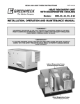
READ AND SAVE THESE INSTRUCTIONS
PART #462255
Energy Recovery Ventilator
®
Model:
APEX-200
INSTALLATION, OPERATION, & MAINTENANCE MANUAL
Energy recovery wheels certified by the ARI Air-to-Air
Energy Recovery Ventilation Equipment Certification
Program in accordance with ARI Standard 1060.
Actual performance in packaged equipment may vary.
Certified Ratings are available in the Certified Product
Directory at http://www.ari.org/directories/erv
RECEIVING AND HANDLING
The APEX is thoroughly inspected and test run at the factory. However, damage may occur during shipping and
handling. Upon delivery, inspect the unit for both obvious and hidden damage. If damage is found, record all
necessary information on the bill of lading and file a claim with the final carrier. In addition, ensure all accessory
items are present. Some accessory items are stored inside the unit during shipping.
SAFETY WARNING
Improper installation, adjustment, alteration, service or maintenance can cause property damage, injury or death.
Read this installation, operation, and maintenance manual thoroughly before installing or servicing this equipment.
WARRANTY
Greenheck warrants this equipment to be free from defects in material and workmanship for a period of one year
from the purchase date. The energy recovery wheel is warranted to be free from defects in material and
workmanship for a period of five years from the purchase date. Any units or parts which prove defective during the
warranty period will be replaced at our option when returned to our factory, transportation prepaid.
Motors are warranted by the motor manufacturer for a period of one year. Should motors furnished by Greenheck
prove defective during this period, they should be returned to the nearest authorized motor service station.
Greenheck will not be responsible for any removal or installation costs.
INSTALLATION SUPPLEMENT
Refer to the following installation supplement for APEX
units supplied with a Temperature Control Package:
Temperature Control Package, Part #461468
Refer to the following installation supplement for APEX
units supplied with a Greenheck roof curb, Model GKD:
APEX Roof Curb IOM, Part #462831
SAVE THIS MANUAL
This manual is the property of the
owner, and is required for future
maintenance. This manual should
remain with each APEX unit when
the job is complete.
Table of Contents
Storage . . . . . . . . . . . . . . . . . . . . . . . . . . . 2
General . . . . . . . . . . . . . . . . . . . . . . . . . . . 3
Installation . . . . . . . . . . . . . . . . . . . . . . . . 3
Lifting . . . . . . . . . . . . . . . . . . . . . . . . . . . .3
Unit weights . . . . . . . . . . . . . . . . . . . . . . .4
Recommended roof openings . . . . . . . .4
Roof curb mounting . . . . . . . . . . . . . . . .4
Rail mounting . . . . . . . . . . . . . . . . . . . . . 5
Weatherhoods / Dampers . . . . . . . . . . . 5
Electrical connections . . . . . . . . . . . . . .6
Service Clearances . . . . . . . . . . . . . . . . . 7
Access Locations . . . . . . . . . . . . . . . . . . 7
Dimensional Data . . . . . . . . . . . . . . . . . . .7
Access Door Descriptions . . . . . . . . . . .7
Coil Application Recommendations . . . 8
Water coils . . . . . . . . . . . . . . . . . . . . . . . 8
DX coils . . . . . . . . . . . . . . . . . . . . . . . . . 8
Drain pan trap piping . . . . . . . . . . . . . . . 9
Electric Heater Application/Operation .9
Variable Frequency Drive . . . . . . . . . . . .9
Frost Control Application/Operation . .10
Economizer Application/Operation . . .11
Optional Accessories . . . . . . . . . . . .12-13
Start-Up Checks . . . . . . . . . . . . . . . . . . 14
Fan information . . . . . . . . . . . . . . . . . . 15
Fan belt drives . . . . . . . . . . . . . . . . . . . .16
Fan RPM . . . . . . . . . . . . . . . . . . . . . . . .16
Vibration . . . . . . . . . . . . . . . . . . . . . . . . .17
Energy recovery wheel . . . . . . . . . . . . 17
Routine Maintenance . . . . . . . . . . . . . . 18
Lubrication / Dampers / Belts . . . . . . .18
Motors . . . . . . . . . . . . . . . . . . . . . . . . . .19
Wheel and fasteners . . . . . . . . . . . . . . .19
Bearings . . . . . . . . . . . . . . . . . . . . . . . . .19
Filters / Door Seals . . . . . . . . . . . . . . . 20
Coil Maintenance . . . . . . . . . . . . . . . . . . .21
Maintenance . . . . . . . . . . . . . . . . . . . . .21
Winterizing . . . . . . . . . . . . . . . . . . . . . .21
Energy Recovery Wheel Maintenance 22
Accessing energy recovery wheel . . . .22
Removing wheel segments . . . . . . . . .22
Cleaning wheel segments . . . . . . . . . . .23
Wheel belt / Wheel bearings . . . . . . . .23
Parts List . . . . . . . . . . . . . . . . . . . . . . . . .24
Sequence of Operation . . . . . . . . . . . . .25
Airflow Troubleshooting . . . . . . . . . . . .26
General Troubleshooting . . . . . . . . .27-28
Storage
When a unit is not going to be in service for an extended amount of time, certain procedures should be
followed to keep the fans in proper operating condition.
• Rotate fan wheel monthly and purge grease from bearings once every three months
• Cover unit with tarp to protect from dirt and moisture (Note: do not use a black tarp as this will promote
condensation)
• Energize fan motor once every three months
• Store belts flat to keep them from warping and stretching
• Store unit in location which does not have vibration
• After storage period, purge grease from fan bearings before putting fan into service
If storage of unit is in a humid, dusty or corrosive atmosphere, rotate the fan and purge the bearings once a
month. Improper storage which results in damage to the unit or components will void the warranty.
2
®
Basic Unit Operation
The APEX brings in
fresh, outdoor air and
removes stale, exhaust
air. Prior to discharging
the exhaust air, the
energy recovery wheel
transfers energy from
the exhaust air to the
outdoor air at an
efficiency of 70-80%.
Simply put, this unit
preconditions the
outdoor air to save
money on heating and
cooling costs. This
particular unit also has
cooling and heating
options available after
the recovery wheel to
further condition the
fresh air temperature if
desired.
Energy Recovery Wheels
Exhaust Air
discharged outside
Top View
Fresh
Outdoor Air
Exhaust Air
discharged outside
Optional Cooling &
Heating Coils
Side View
Fresh
Outdoor Air
Preconditioned Air
sent to RTU or AHU
Exhaust Air
from building
Installation
The system design and installation should follow
accepted industry practice, such as described in the
ASHRAE Handbook.
SAFETY WARNING
All factory provided lifting lugs must be used
when lifting the units. Failure to comply with
this safety precaution could result in
property damage, serious injury, or death.
Adequate space should be left around the unit for
piping coils and drains, filter replacement, and
maintenance. Sufficient space should be provided on
the side of the unit for routine service and component
removal should that become necessary. See Service
Clearances for more details.
Lift using lifting lugs
and spreader bars
Lifting
1) Before lifting, be sure that all shipping material has
been removed from unit.
2) To assist in determining rigging requirements,
weights are shown on next page.
3) Unit must be lifted by the eight lifting lugs provided
on base structure.
4) Rigger to use suitable mating hardware to attach to
unit lifting lugs.
5) Two spreader bars must span the unit to prevent
damage to the cabinet by the lift cables.
6) Always test-lift the unit to check for proper balance
and rigging before hoisting to desired location.
7) Never lift units by weatherhoods.
8) Never lift units in windy conditions.
9) Preparation of curb and roof openings should be
completed prior to lifting unit to the roof.
10) Do not use fork lifts for handling unit.
3
FIGURE 1: Example diagram of lifting the APEX
®
Installation
Unit Weights (dry weights)
Unit
Approx. Weight (lbs)
APEX-200 (without coils)
9,000
APEX-200 (with HW & CW coils)
12,000
Recommended Roof Openings
W
Exhaust
Air
Intake
Outdoor
Air
Discharge
Model
A
B
C
D
APEX-200
86
44
68.75
44
All dimensions shown are in inches.
A
Curb Outside Dimensions
D
C
L
FIGURE 2: Recommended roof openings.
B
2.50
From Inside Curb
To Recommended
Roof Opening
Model
L
W
APEX-200
283.5
92.0
Dimensions shown are in inches.
Roof Curb Mounting
Rooftop units require curbs to be mounted first. The
duct connections must be located so they will be clear
of structural members of the building.
1. Factory Supplied Roof Curbs
Roof curbs are Model GKD, which are shipped in a
knockdown kit and require field assembly (by others).
Assembly instructions are included with the curb.
2. Cut Roof Opening and Locate Curb
Layout the unit roof openings such that the supply
discharge & exhaust inlet of the unit will line up with
the corresponding ductwork (refer to Recommended
Roof Openings). Do not make openings larger than
necessary. Be sure to allow for the recommended
service clearances. Keep the supply inlet of the unit
away from any other exhaust fans. Likewise, position
the exhaust discharge opening away from fresh air
intakes of any other equipment.
3. Install Curb
Locate curb over roof opening and fasten in place.
Check that the diagonal dimensions are within ± 1⁄8
inch of each other and adjust as necessary. Shim as
required to level.
4. Set the Unit
Lift unit to a point directly above the curb and duct
openings. Guide unit while lowering to align with
duct openings. Roof curbs fit inside the unit base.
Make sure the unit is properly seated on the curb
and is level.
Duct Size:
80 in. x 30 in.
FIGURE 3: Duct dimensions.
BASE
SIDE OF UNIT
2.00
6.00
2.00
2 IN. INSULATION
1.25
0.75
5. Duct Work
Installation of all ducts should be done in
accordance with SMACNA and AMCA guidelines.
ROOF CURB
FIGURE 4: Roof curb details.
Dimensions based on Greenheck-supplied roof curb only!
4
®
Installation
Rail Mounting
Rail Layout
• Rails designed to handle the weight of the APEX should be positioned as shown on the diagrams below
(rails by others).
•
Make sure that rail positioning does not interfere with the supply air discharge opening or the exhaust air
intake opening on the APEX unit (see FIGURE 6).
•
Rails should run the width of the unit and extend beyond the unit a minimum of 12 inches on each side (see
FIGURE 5).
•
Set unit on rails.
Outdoor
Air
Intake
Hood
Exhaust Air
Discharge Hood
EXHAUST
INLET
OPENING
SUPPLY
DISCHARGE
OPENING
7.00
52.00
118.00
160.00
FIGURE 5: Isometric view of APEX on rails.
FIGURE 6: Side view of APEX on rails.
Weatherhoods
Supply weatherhood will be factory mounted. There are two
exhaust weather hoods shipped separately as a kit with
instructions on how to mount (refer to Page 7 for hood locations).
Dampers
Backdraft dampers are always included as an integral part
of the exhaust hood assemblies. Motorized outdoor air
and exhaust air dampers are optional and are factory
mounted (and wired) at the inlet.
An optional motorized damper is also available for
recirculation mode. This damper allows 100% recirculation
of exhaust air through the coils for continued tempering of
the space during unoccupied mode (i.e. no outdoor air
being brought in). This damper is mounted and wired at
the factory.
5
®
Installation
Electrical Connections
SAFETY DANGER!
The electrical supply must be compatible with that shown on
the nameplate: voltage, phase, and amperage capacity.
Connect power to the unit per the unit specific wiring diagram
located on the inside of the control center access door. The
wiring diagram indicates which electrical accessories were
provided on the unit. The electrical supply line must be properly
fused and conform to local and national electrical codes.
Electric shock hazard. Can cause injury or
death. All wiring should be performed by a
qualified electrician. Before attempting to
perform any service or maintenance, turn
the electrical power to unit to OFF at
disconnect switch(es). Unit may have
multiple power supplies.
All internal electrical components are pre-wired at the factory. To
SAFETY CAUTION!
determine what specific electrical accessories were provided with
Verify
power
before wiring the supply and
the unit, refer to the unit specific wiring diagram located in the unit
control voltage. Greenheck is not
control center. Field electrical connections required:
responsible for any damage to, or failure of
1) supply power to the main disconnect (See FIGURE 7,
the unit caused by incorrect field wiring.
Item #1). A door interlocking safety disconnect is
provided as a standard feature.
2) low voltage control power to the 24 VAC control circuit (See FIGURE 7, Item #7).
IMPORTANT: Use minimum 14 ga. wire for 24 volt control power. Control wire resistance should not
exceed 0.75 ohms (approximately 285 feet total length for 14 ga. wire; 455 feet total length for 12 ga.
wire). If wire resistance exceeds 0.75 ohms, an industrial-style, plug-in relay should be added to the
unit control center and wired in place of the remote switch (typically between terminal blocks R and G
on the control strip — See FIGURE 7, Item #7). The relay must be rated for at least 5 amps and have
a 24 VAC coil. Failure to comply with these guidelines may cause motor starters to “chatter” or not
pull in which can cause contactor failures and/or motor failures.
Control wires should not be run inside the same conduit as that carrying the supply power. The unit must be
electrically grounded in accordance with the current National Electrical Code, ANSI/NFPA-70.
Note:
Standard factory installed electric pre-heaters and post-heaters have their own disconnect separate
from the unit disconnect. Thus, each electric heater requires its own separate power connection.
Typical Control Center Components
1.
2.
3.
4.
5.
6.
Main Disconnect
Motor Starter — Exhaust Air Fan #1
Motor Starter — Exhaust Air Fan #2
Motor Starter — Outdoor Air Fan
Energy Wheels Motor Contactor
Control Power Transformer
(24 VAC Secondary)
7. 24 VAC Terminal strip
8. Fuses for the control circuit, wheel drive
transformer, and blower motors.
9. Energy Wheel Motor Transformer (230 VAC
Secondary - for units with primary voltage
greater than 230 VAC) (transformer not shown)
1
6
8
7
5
2
3
4
FIGURE 7: Typical control center components.
6
®
Installation
Service Clearances / Access Locations
APEX-200 units require minimum clearances for access on all sides for routine maintenance. Filter replacement,
drain pan inspection and cleaning, energy wheel cassette inspection, fan bearing lubrication and belt
adjustment, are examples of routine maintenance that must be performed. Blower and motor assemblies,
energy recovery wheel cassettes, coil and filter sections are always provided with a service door or panel for
proper component access. Clearances for component removal may be greater than the service clearances.
Contact Greenheck for component removal clearance.
Exhaust
Hood
36 in.
Outdoor Air
Intake Hood
29 in.
Exhaust
Air
Wheel Cassettes
Inlet
2 in.
Filters
96 in.
Coil
Section
Control
Center
Exhaust
Hood
36 in.
FIGURE 8: Clearances for service on APEX-200
Dimensional Data / Access Door Descriptions
Model
A
APEX-200 287.75
B
96.5
C
92.5
Exterior Dimensions
D
E
F
58.75 15.75
31
Width (just unit):
Width (including lifting lugs):
Overall Width (with exhaust hoods):
Overall Length (with outdoor air hood):
96.5
99.875
146.75
303.5
4
5
3
C
E
7
1
8
6
D
1
10
11
9
F
H
I
B
G
H*
I*
24.63 25.125
Following is a list of items accessible through the
access doors shown on the diagram at the left. Some
items are optional and may not have been provided.
1) Exhaust blower #1, energy recovery wheel #1
maintenance (segment removal for cleaning)
2) Half of supply filters
3) Exhaust filters (refer to Filter Maintenance).
Energy recovery wheel motors, belts, and seals
4) Supply blower, motor, and drives
5) Supply blower and drives
6) Coil drain pan and electric heater
7) Control center, variable frequency drives, and
temperature control package
8) Half of supply filters
9) Exhaust blower #2, energy recovery wheel #2
maintenance (segment removal for cleaning)
10) Outdoor air damper, electric preheater, frost
control sensors, and economizer sensors
11) Aluminum mesh filters (both sides of hood)
(All dimensions shown are in inches.)
2
G
10.75
A
* G, H, & I typical both sides of unit
FIGURE 9: Dimensional data and access door locations.
7
®
Installation
Coil Application Recommendations
Factory installed cooling and heating components are mounted
in the coil section of the unit. The coil section is downstream of
the energy wheel on the supply air side of the unit.
See FIGURE 10 for coil connection location. Coil connections
are located external to the unit as shown. Coil connections that
are not external have been ordered from the factory with
interior or exhaust airstream coil connections.
Note:
Water coil
connections
DX coil liquid
connection
access door
DX coil liquid connections are accessible through
access doors shown in FIGURE 10.
Water Coils
1. Piping should be in accordance with accepted industry standards.
Pipework should be supported independently of the coils. Water
connections are male N.P.T iron pipe. When installing couplings,
do not apply undue stress to the connection extending through
the unit. Use a backup pipe wrench to avoid breaking the weld
between coil connection and header.
Water coil
connections
FIGURE 10
2. Connect the WATER SUPPLY TO THE BOTTOM CONNECTION on the air leaving side and the WATER
RETURN TO THE TOP CONNECTION on the air entering side. To ensure proper venting, an external air vent
in the piping is recommended. Connecting the supply and/or return in any other manner will result in very
poor performance. Be sure to replace factory installed grommets around coil connections if removed for
piping. Failure to replace grommets will result in water leakage into the unit and altered performance.
3. The air vent at the uppermost point should be temporarily opened during system start-up to release all of
the air from the coil. To maintain heat transfer capacity, periodically vent any air in coil.
4. Water coils are not normally recommended for use with entering air temperatures below 40oF; however, the
energy recovery wheel maintains a pre-coil temperature higher than 40oF. No control system can be
depended on to be 100% safe against freeze-up with water coils. Glycol solutions or brines are the only
safe media for operation of water coils with low entering air temperatures.
CONTINUOUS WATER CIRCULATION THROUGH THE COIL AT ALL TIMES IS HIGHLY RECOMMENDED.
5. Pipe sizes for the system must be selected on the basis of the head (pressure) available from the circulation
pump. The velocity should not exceed 6 feet per second and the friction loss should be approximately
3 feet of water column per 100 feet of pipe.
6. For chilled water coils, the condensate drain pipe should be sized adequately to ensure the condensate
drains properly. See Drain Pan Traps and FIGURE 11.
Direct Expansion (DX) Coils
1. Piping should be in accordance with accepted industry standards. Pipework should be supported
independently of the coils. Undue stress should not be applied at the connection to coil headers.
2. The condensate drain pipe should be sized adequately to ensure the condensate drains properly. See Drain
Pan Traps and FIGURE 11.
3. When connecting suction and liquid connections make sure the coil is free from all foreign material. Make
sure all joints are tight and free of leakage. Be sure to replace factory installed grommets around coil
connections if removed for piping.
4. Greenheck does not supply condensing units; for further instruction on DX coil installation and operation
contact your condensing unit manufacturer.
8
®
Installation
Drain Pan Traps
Drain lines and traps should be run full size or larger from
the drain pan connection (drain pan connection is 1.25-inch
diameter female thread). Drain pans should have drain lines
and traps to permit the condensate from the coils to drain
freely. On all units with drain pans, the trap depth and the
distance between the trap outlet and the drain pan outlet
should be twice the static pressure in the drain pan section
under normal operation to assure the trap remains sealed.
6 in. min.
6 in. min.
FIGURE 11: Drain pan trap dimensions.
Electric Heater Application/Operation
Factory installed electric post-heaters can be
provided to warm the air leaving the energy recovery
wheel to a user specified discharge temperature.
Electric heaters are available in 208, 230, or 460 VAC
(refer to heater nameplate for voltage).
field adjustable set point). The four stages will come
on one at a time until the discharge temperature set
point is satisfied). Post-heaters are not single point
wired (see Electrical Connections).
Post-heaters supplied with Greenheck temperature
control package are 3-stage with binary control that
provides 7 steps of heating. For example, a 35 kW
heater with three stages will be composed of 5, 10,
and 20 kW stages. The stages essentially ‘mix and
match’ to provide heat output from 5 kW to 35 kW, in
5 kW increments.
Post-heaters are standard as 4-stage, step control.
Step control heaters are designed with multiple stages
made up of equal increments of heating capability. For
example, an 80 kW heater with four stages will be
composed of four 20-kW stages. Post-heaters come
standard with a discharge temperature sensor (with
Variable Frequency Drive for Fans (E7 Series by Yaskawa)
(see page 13 for VFD on energy recovery wheel)
Factory installed VFDs for the fans are programmed at the factory
per the settings shown in TABLE 1 below (see FIGURE 12 for key
pad). VFDs are shipped with a jumper between A1 to +V to allow
the unit to turn on at full speed until the appropriate control signal
can be applied. Remove the jumper when wiring the appropriate
.0-10 Vdc control signal. See FIGURE 13. Refer to the instruction
manual that ships with the unit when making adjustments. A copy
of the manual can be found online at www.drives.com. For
technical support, contact Yaskawa direct at 1-800-927-5292.
Parameters
Setting Comment
A1-01 Access Level
2
Advanced Level
A1-04 Password
0
Leave as default
b1-01 (Frequency) Ref Source
1
Terminal - Analog Input A1
b1-02 Run (Command) Source
1
Contact Closure on S1
C1-01 Accl Time 1
30
Seconds
30
Seconds
C1-02 Decel Time 2
d2-01 Ref Upper Limit
100% % of E1-04
d2-02 Ref Lower Limit
50%
E1-04 Max Frequency
60 Hz Ref for d2-01, d2-02, H3-03
E2-01 Motor Rated FLA
?A
% of E1-04
Nameplate amps
H3-02 Terminal A1 Gain
100% 10V = 60 Hz, 100% of E1-04
H3-03 Terminal A1 Bias
50%
L8-10
Cooling Fan Operation
O2-03 User Defaults
0V = 30 Hz, 50% of E1-04
0
Fan only during RUN
1
Saves setting as user defaults
Set defaults by A1-03 = 1110
A1-01 Access Level
FIGURE 12: VFD key pad & LCD
0
FIGURE 13: Control signal to VFD
Operation Only
TABLE 1: Factory settings for VFD used on fans
9
®
Installation
Frost Control Application/Operation
Extremely cold outdoor air temperatures can cause moisture condensation and frosting on the energy recovery
wheel. Frost control is an optional feature that will prevent/control wheel frosting. Three options are available:
1) Timed Exhaust frost control
2) Electric preheat frost control
3) Modulating wheel frost control
Indoor RH @ 70°F
20%
30%
40%
Frost Threshold Temp
-10°F
-5°F
0°F
All of these options are provided with a thermostat (with
TABLE 2: Frost threshold temperatures
probe) mounted in the supply air inlet compartment (see
FIGURE 15) and a pressure sensor to monitor pressure drop
across the wheel. The typical temperature setting corresponds to the indoor air relative humidity as shown in
Table 2 and represents when frost can occur. An increase in pressure drop would indicate that frost is
occurring. Both the pressure sensor AND the outdoor air temperature sensor must trigger in order to initiate
frost control. The two sensors together insure that frost control is only initiated during a real frost condition. The
following explains the three options in more detail.
Timed exhaust frost control includes a timer in addition to the thermostat and
pressure sensor. When timed exhaust frost control is initiated, the timer will turn the
supply blower on and off to allow the warm exhaust air to defrost the energy recovery
wheel. Default factory settings are 5 minutes off and 30 minutes on. Use the following
test procedure for troubleshooting.
Testing (refer to FIGURE 14)
• Jumper the pressure switch. Set the Timer Scale for T1 and T2 to 1
minute. Set the Timer Settings for T1 and T2 to 1.0. Set the dip switch to
the down position.
• Turn the temperature sensor up as high as possible. The supply blower
should cycle on for one minute, then turn off for one minute.
• After testing, set the Timer Scale as follows: T1 = 10 minutes, T2 = 1 hour
• Set the Timer Settings as follows: T1 = 0.5, T2 = 0.5. The timer is now set
for 5 minutes off and 30 minutes on. Remember to remove the jumper.
A1
B1
15
0.8 0.6
1.0
0.4
0
T2
Dip
Switch
0.2
1 MIN T2
Timer
Scale
1 MIN T1
0.8 0.6
1.0
0.4
0
0.2
T1
16
18
A2
FIGURE 14
Electric preheat frost control includes an electric heater (outdoor air inlet) and an air pressure switch
(outdoor air outlet) in addition to the thermostat and pressure sensor on wheel. When electric preheat frost
control is initiated, the electric pre-heater will turn on and warm the air entering the energy wheel to avoid
frosting. Use the following test procedure for troubleshooting.
Testing
• Turn the thermostat as high as it will go and jumper the wheel pressure
sensor. The heater should turn on.
• If it doesn’t, either put the supply side doors on or temporarily jumper the
air pressure switch to avoid nuisance tripping of the pressure switch.
Remember to remove the jumpers.
Modulating wheel frost control includes a variable frequency drive in addition to the thermostat and pressure
sensor. When modulating wheel frost control is initiated, the variable frequency drive will reduce the speed of
the wheel. Reducing the speed of the energy wheel reduces its effectiveness, which keeps the exhaust air
condition from reaching saturation, thus, eliminating condensation and frosting. If the outdoor air temperature is
greater than the frost threshold temperature OR the pressure differential is less than the set point, the wheel will
run at full speed. If the outdoor air temperature is less than the frost threshold temperature AND the pressure
differential is greater than the set point, the wheel will run at minimum speed until the pressure differential falls
below the set point. The temperature and pressure differential set points are set at the factory, but are fieldadjustable. The variable frequency drive will be fully programmed at the factory.
10
®
Installation
Economizer Application/Operation
The energy recovery wheel operation can be altered to take advantage of economizer operation (free cooling).
Two modes are available: 1) De-energizing the wheel or 2) Modulating the wheel.
De-energizing the wheel is accomplished with a signal from a Temperature or Enthalpy sensor mounted in
the supply air inlet compartment (see FIGURE 15). This Primary sensor will de-energize the energy wheel when
the outdoor air temperature (factory default is 65°F) or enthalpy (factory default is the ‘D’ setting) is below the
field adjustable set point. An Override temperature sensor is also furnished in the supply air inlet compartment
to deactivate economizer mode (see FIGURE 15). The Override (with field adjustable set point) is set at some
temperature lower than the Primary sensor (factory default is 50°F). Effectively, the two sensors create a
deadband where the energy recovery wheel will not operate and free cooling from outside can be brought into
the building unconditioned.
Testing (terminals referenced below are in the unit control center — see FIGURE 7, Item #7)
Temperature sensor with Override
• Turn both Temperature and Override thermostats down
as low as they go. The wheel should be rotating.
• Turn the Temperature sensor up as high as it goes, and
keep the Override sensor as low as it will go. The wheel
should stop rotating.
• Turn both sensors as high as they will go. The wheel
Override
should start rotating.
• Set the Temperature sensor at desired point for
economizer operation to begin. Set the Override sensor
at desired point for economizer operation to end
(factory default is 65°F and 50°F, respectively).
Probes
FIGURE 15
Enthalpy Sensor
(Primary Sensor)
Timed Exhaust
Frost Control
Enthalpy sensor with Override
• A factory-installed 620 ohm resistor is connected across terminals SR and +. The Override sensor
should be turned down below current temperature in unit. Turn the unit on; LED on the sensor should
be off. Confirm continuity across terminals 1 and 2 and no continuity across terminals 2 and 3.
• Disconnect the 620 ohm resistor from terminals SR and +. LED should turn on. Confirm continuity
across terminals 2 and 3 and no continuity across terminals 1 and 2.
• Turn Override sensor above current temperature in unit. Confirm continuity across terminals 3 and 6.
Set the Override sensor to the desired point for economizer operation to end (factory default is 50°F).
• Reconnect the factory-installed jumper.
Modulating the Wheel
In applications in which an internal heat gain is present in the space, the rotational speed of the energy wheel
may be modulated (via variable frequency drive) to avoid overheating the space during the winter. The speed of
the energy wheel will be controlled in response to the discharge temperature set point.
Sequence of Operation: The variable frequency drive is fully programmed at the factory. A ‘call for cool’ must
be field wired to the unit (terminals provided in unit - refer to wiring diagram in unit control center) to allow for
initiation of economizer mode. When the space calls for cooling, factory supplied controls will drive the
following wheel operations:
:
Wheel runs at full speed (maximum energy recovery)
TOA > TRA
TOA < TRA and TOA > TSA
:
Wheel is stopped (no energy recovery)
:
Wheel will modulate to maintain discharge temperature
TOA < TRA and TOA < TSA
where (TOA) is the outdoor air temperature set point, (TRA) is the return air temperature set point, and (TSA) is the
supply air discharge thermostat set point (nominal 60°F – not adjustable).
11
®
Optional Accessories
Rotation Sensor
The rotation sensor monitors energy recovery wheel rotation. If the wheel should stop rotating, the sensor will
close a set of contacts in the unit control center. Field wiring of a light (or other alarm) to these contacts will
notify maintenance personnel when a failure has occurred.
Dirty Filter Sensor
Dirty filter sensors monitor pressure drop across the outdoor air filters, exhaust air filters, or both. If the
pressure drop across the filters exceeds the set point (set at factory), the sensor will close a set of contacts in
the unit control center. Field wiring of a light (or other alarm) to these contacts will notify maintenance
personnel when filters need to be replaced.
Temperature Control Package
Temperature control package allows for stand-alone operation
of energy recovery units provided with supplemental cooling
and heating. Controller can be ordered for discharge or room
control. Room control would require a room thermostat (or
other call for heat) be wired to the controller. A remote panel
option is also available to allow set points and other controller
parameters to be adjusted from a remote location. For
additional information, refer to the following documents:
Catalog: Temperature Control Package
IOM: Temperature Control Package, Part #461468
CO2 Sensor
This accessory is often used to provide a modulating control signal to a variable frequency drive to raise and
lower airflow in relationship to the CO2 levels in the space. This strategy is often referred to as Demand Control
Ventilation and provides further energy savings to the system.
Service Outlet
120 VAC GFCI service outlet ships loose for field installation.
Requires separate power source so power is available when unit
main disconnect is turned off for servicing.
Vapor Tight Lights
Vapor tight lights provide light to each of the
compartments in the energy recovery unit. The
lights are wired to a switch mounted on the
outside of the unit. The switch requires a separate
power source to allow for power to the lights
when the unit main disconnect is off for servicing.
12
®
Optional Accessories
Remote Control Panel
The remote panel is a series of junction boxes ganged together
and includes a stainless steel face plate. The remote panel is
available with a number of different alarm lights and switches to
control the unit. The remote panel ships loose and requires
mounting and wiring in the field. Refer to “Remote Panel Wiring
Schematics” (Part #461368) for instructions on wiring the remote
panel to the 24 VAC terminal strip in the energy recovery unit
control center.
The remote panel is available with the following options:
1) Unit on/off switch
2) Unit on/off light
3) 7-day time clock
4) Hand/off/auto switch
5) Time delay override
6) Exhaust air dirty filter light
7) Outdoor air dirty filter light
8) Economizer light
9) Frost control light
10) Wheel rotation sensor light
Variable Frequency Drive for Energy Recovery Wheel (GPD-305 Series by Yaskawa)
Factory installed VFD for the energy recovery wheel are
programmed at the factory per the settings shown in TABLE 4
below. Refer to the instruction manual that ships with the unit
when making adjustments. A copy of the manual can be found
online at www.drives.com. For technical support, contact Yaskawa
direct at 1-800-927-5292.
Parameters
Setting Comment
n01
Access Level
1
n01 - n79 can be read or set
n02
Operation Method
1
Terminal
n03
Reference Selection
2
0-10 Vdc (mod. wheel econ.)
n09
Max Frequency
n16
Accl Time 1
10
Seconds
n17
Decel Time 2
10
Seconds
n29
Jog Frequency
6 Hz
n30
Ref Upper Limit
100% % of n09
n31
Ref Lower Limit
0%
n32
Motor Rated FLA
?A
n36
Multi-Function Input
10
n40
Frequency Detection
4
n41
Analog Freq. Ref. Gain
0
Inverse acting
n42
Analog Freq. Ref. Bias
99
Inverse acting
n58
Freq. Dectection Level
5.9 Hz
n01
Access Level
60 Hz
0
VFD key pad & LCD
% of n09
n01 read or set; n02-n79 read
TABLE 4: Factory settings for VFD used on energy recovery wheel
13
®
Unit Start-Up
SAFETY DANGER!
SAFETY CAUTION!
Electric shock hazard. Can cause injury or death.
Before attempting to perform any service or
maintenance, turn the electrical power to unit to OFF
at disconnect switch(es). Unit may have multiple
power supplies.
Use caution when removing access panels or other
unit components, especially while standing on a
ladder or other potentially unsteady base. Access
panels and unit components can be heavy and
serious injury may occur.
SAFETY CAUTION!
Do not operate energy recovery ventilator without the
filters and birdscreens installed. They prevent the entry
of foreign objects such as leaves, birds, etc.
For proper unit function and safety, follow everything in this start-up procedure in the order presented. Perform
procedure after the electrical connections are complete.
Pre-Start Check List
1. Disconnect and lock-out all power switches.
2. Remove any foreign objects that are located in the energy recovery unit.
3. Check all fasteners, set screws, and locking collars on the fans, bearings, drives, motor bases and
accessories for tightness.
4. Rotate the fan wheels and energy recovery wheels by hand and ensure no parts are rubbing. If rubbing
occurs, refer to the following Fan or Energy Recovery Wheel section.
5. Check the fan belt drives for proper alignment and tension (see following Fan Belt section).
6. Filters can load up with dirt during construction. Replace any dirty pleated filters and clean the
aluminum mesh filters in the intake hood (refer to Routine Maintenance section).
7. Verify that dampers open and close properly.
Special Tools Required
•
•
•
•
•
Voltage meter
Amperage meter (with wire probes)
Incline manometer or equivalent
Tachometer
Thermometer
Energy Recovery Wheel
(2 per unit)
Outdoor Air Pleated Filters
(both sides of unit)
Refer to Page 3 for Airflow Diagram
*Motorized Outdoor Air
Intake Damper Location
Outdoor Air Intake Hood
(contains aluminum
mesh filters)
Plenum
Supply Fan
Forward Curved Exhaust Fan
(one on each side of unit)
Exhaust Air Pleated Filters
(access inside unit)
*Coil Section
(connections this
side or internal)
*Motorized Exhaust Air Intake Damper Location
(integral backdraft damper in exhaust hoods)
*Indicates an optional accessory.
14
®
Unit Start-Up
Supply Fan (Plenum Type)
The APEX-200 contains one plenum supply fan located on the end of the
unit opposite the outdoor air intake (see beginning of Unit Start-Up section
for diagram of unit layout). Efficient fan performance can be maintained by
having the correct radial gap and overlap. These items should be checked
before start-up and after the fan has been in operation for 24 hours.
Radial Gap: Radial gap is
adjusted by loosening the inlet
cone/ring on the wheel. If
additional adjustment is required
to maintain a constant radial gap,
loosening the bearing bolts and
centering the wheel is acceptable
as a secondary option.
Overlap: Proper overlap is
obtained by loosening the wheel
hub from the shaft and adjusting
the wheel to maintain an ‘A’
dimension of 11 7⁄16 ± 3⁄8 inches
(see FIGURE 16).
Overlap
A
Radial
Gap
FIGURE 16: Radial gap
and overlap
Spring Vibration Isolators on Supply Fan
Three to four Z-brackets prevent unwanted fan and isolator movement
during shipping. Proper unit operation requires the removal of these
brackets.
1. Remove the 5/16 in. hex head bolts from each Z-bracket and fan base.
2. Pull Z-bracket out from the fan base.
3. Replace the bolts to their original position in the fan base.
Exhaust Fans (Forward Curved Type)
The APEX-200 contains two forward curved exhaust fans located on
either side of the unit (see Basic Unit Operation). These forward curved
fans should be checked for free rotation. If any binding occurs, check
for concealed damage and foreign objects in the fan housing. Be sure
to check the belt drives per the start-up recommendations in the
following section.
Fan Performance Modifications
Due to job specification revisions, it may be necessary to
adjust or change the sheave or pulley to obtain the desired
airflow at the time of installation. Start-up technician must
check blower amperage to ensure that the amperage listed
on the motor nameplate is not exceeded. Amperage to be
tested with access doors closed and ductwork installed.
15
SAFETY CAUTION!
When operating conditions of the fan are to be
changed (speed, pressure, temperature, etc.),
consult Greenheck to determine if the unit can
operate safely at the new conditions.
®
Unit Start-Up
Fan Belt Drives
The fan belt drive components, when supplied by Greenheck Fan Corporation, have been carefully selected for
the unit's specific operating condition. Caution: utilizing different components than those supplied could result in
unsafe operating conditions which may cause personal injury or failure of the following components: 1) Fan
Shaft, 2) Fan Wheel, 3) Bearings, 4) Belt, 5) Motor. Tighten all fasteners and set screws securely and realign drive
pulleys after adjustment. Check pulleys and belts for proper alignment to avoid unnecessary belt wear, noise,
vibration and power loss. Motor and drive shafts must be parallel and pulleys in line (see FIGURES 17 & 18).
Belt Drive Installation
1. Remove the protective coating from the end of the fan shaft and ensure
that it is free of nicks and burrs.
2. Check fan and motor shafts for parallel and angular alignment.
3. Slide sheaves on shafts - do not drive sheaves on as this may result in
bearing damage.
4. Align fan and motor sheaves with a straight-edge or string and tighten.
5. Place belts over sheaves. Do not pry or force belts, as this could result in
damage to the cords in the belts.
6. With the fan off, adjust the belt tension by moving the motor base. (See
belt tensioning procedures in the Routine Maintenance section of this
manual). When in operation, the tight side of the belts should be in a
straight line from sheave to sheave with a slight bow on the slack side.
WRONG
WRONG
WRONG
FIGURE 17: Aligning
sheaves with a
straight edge
CORRECT
FIGURE 18: Proper alignment of motor and drive shaft.
Fan RPM
Supply fan will have a fixed motor pulley. Exhaust fans will have an adjustable motor
pulley (on 15 HP and below) preset at the factory to the customer specified RPM. Fan
speed can be increased or decreased by adjusting the pitch diameter of the motor pulley.
Multi-groove variable pitch pulleys must be adjusted an equal number of turns open or
closed. For the exhaust blowers, any increase in fan speed represents a substantial
increase in load on the motor. Always check the motor amperage reading and compare it
to the amperage rating shown on the motor nameplate when changing fan RPM.
For Exhaust Fans. All access doors must be installed except the control center door.
Close off as much of the exhaust blower access opening as possible while measuring the
amp draw. Do not operate units with access doors open or without proper ductwork in
place as the exhaust motors will overload.
16
®
n
Airflow
R ota
Blower access is labeled on unit. Check for proper wheel rotation by momentarily
energizing the fan. Rotation is determined by viewing the wheel from the drive side and
should match the rotation decal affixed to the fan housing (see FIGURE 19). If the wheel
is rotating the wrong way, direction can be reversed by interchanging any two of the
three electrical leads. Check for unusual noise, vibration, or overheating of bearings.
Refer to the “Troubleshooting” section of this manual if a problem develops.
ti o
Direction of Fan Wheel Rotation
Rotation
FIGURE 19
Unit Start-Up
Vibration
Excessive vibration maybe experienced during initial start-up. Left unchecked, excessive vibration can cause a
multitude of problems, including structural and/or component failure. The most common sources of vibration
are listed below.
1.
2.
3.
4.
5.
6.
7.
8.
9.
Wheel Unbalance
Drive Pulley Misalignment
Incorrect Belt Tension
Bearing Misalignment
Mechanical Looseness
Faulty Belts
Drive Component Unbalance
Poor Inlet/Outlet Conditions
Foundation Stiffness
Many of these conditions can be discovered by careful observation. Refer to
the troubleshooting section of this manual for corrective actions. If
observation cannot locate the source of vibration, a qualified technician using
vibration analysis equipment should be consulted. If the problem is wheel
unbalance, in-place balancing can be done.
Generally, fan vibration and noise is transmitted to other parts of the building
by the ductwork. To eliminate this undesirable effect, the use of heavy canvas
connectors is recommended.
Energy Recovery Wheel
The APEX contains two energy recovery wheels (see
FIGURES 20 & 21). These wheels are inspected for
proper mechanical operation at the factory. However,
during shipping and handling, shifting can occur that may
affect wheel operation. Wheels are accessible through the
access doors marked "Energy Wheel Cassette Access".
Due to the size and weight of these wheels, they remain
stationary and all maintenance is performed in place.
There is ample room inside the unit to perform energy
recovery wheel servicing.
Turn the energy recovery wheels by hand to verify free
operation. The wheel should rotate smoothly and should
not wobble.
FIGURE 20: Inside layout of APEX unit
Drive Belt
Inspect the drive belt. Make sure the belt rides smoothly through the pulley and over the wheel rim.
Air Seals
Air seals are located around the perimeter of the
wheel and across the face of the wheel (both sides of
wheel). Check that these seals are secure and in
good condition.
Air seals which are too tight will prevent proper
rotation of the energy recovery wheel. Air seal
clearance may be checked by placing a sheet of
paper, to act as a feeler gauge, against the wheel
face. To adjust the air seals, loosen all eight seal
retaining screws. These screws are located on the
bearing support that spans the length of the cassette
through the wheel center. These seals are located on
each side of the wheel; be sure to check both of
them. Adjust the seals such that they tug slightly on
the sheet of paper as the wheel is turned. Tighten the
retaining screws.
Bearing Support
Adjustable
Air Seals
Label showing
cassette serial #
and date code
Drive Belt
Drive Pulley
Replace access doors and apply power. Observe that
the wheels rotate freely at about 60 RPM. If wheels
do not rotate or are binding, contact your local
representative.
FIGURE 21: Energy recovery wheel components
17
®
Routine Maintenance
SAFETY DANGER!
SAFETY CAUTION!
Electric shock hazard. Can cause injury or death.
Before attempting to perform any service or
maintenance, turn the electrical power to unit to OFF
at disconnect switch(es). Unit may have multiple
power supplies.
Use caution when removing access panels or other
unit components, especially while standing on a
ladder or other potentially unsteady base. Access
panels and unit components can be heavy and
serious injury may occur.
Once the unit has been put into
operation, a routine
maintenance program should
be set up to preserve reliability
and performance. Items to be
included in this program are:
•
•
•
•
•
Lubrication
Dampers
Fan Belts
Motors
Wheel & Fasteners
•
•
•
•
Bearings
Filter Maintenance
Coil Maintenance
Energy Wheel Cassette
Lubrication
Check all moving components for proper lubrication. Apply lubrication where required. Any components
showing excessive wear should be replaced to maintain the integrity of the unit and ensure proper operation.
Dampers
Check all dampers to ensure they open and close properly and without binding. Backdraft dampers can be
checked by hand to determine if blades open and close freely. Apply power to motorized dampers to ensure
the actuator opens and closes the damper as designed.
Fan Belts
Belts must be checked on a regular basis for wear, tension, alignment, and dirt accumulation. Premature or
frequent belt failures can be caused by improper belt tension (either too loose or too tight) or misaligned
sheaves. Abnormally high belt tension or drive misalignment will cause excessive bearing loads and may result
in failure of the fan and/or motor bearings. Conversely, loose belts will cause squealing on start-up, excessive
belt flutter, slippage, and overheated sheaves. Both loose and tight belts can cause fan vibration.
When replacing belts on multiple groove drives, all belts should be changed to provide uniform drive loading.
Do not pry belts on or off the sheave. Loosen belt tension until belts can be removed by simply lifting the belts
off the sheaves. After replacing belts, ensure that slack in each belt is on the same side of the drive. Belt
dressing should never be used.
Do not install new belts on worn sheaves. If the sheaves have grooves worn in them, they must be replaced
before new belts are installed.
Deflection =
Belt Span
64
The proper belt setting is the lowest tension at
which the belts will not slip under peak load
operation (see FIGURE 22). For initial tensioning,
set the belt deflection at 1⁄64-inch for each inch of
belt span (measured half-way between sheave
centers). For example, if the belt span is 64 inches,
the belt deflection should be 1 inch (using
moderate thumb pressure at mid-point of the
drive). Check belt tension two times during the first
24 hours of operation and periodically thereafter.
Belt Span
FIGURE 22: Proper fan belt settings
18
®
Routine Maintenance
Motors
Motor maintenance is generally limited to cleaning and lubrication. Cleaning
should be limited to exterior surfaces only. Removing dust and grease
buildup on the motor housing assists proper motor cooling. Never washdown motor with high pressure spray. Greasing of motors is only intended
when fittings are provided. Many fractional motors are permanently
lubricated for life and require no further lubrication. Motors supplied with
grease fittings should be greased in accordance with the manufacturer's
recommendations. When motor temperature does not exceed 104°F (40°C),
the grease should be replaced after 2000 hours of running time.
Wheel & Fasteners
Wheels require very little attention when moving clean air. Occasionally oil and dust may accumulate on the
wheel causing imbalance. When this occurs the wheel and housing should be cleaned to ensure smooth and
safe operation. Inspect fan impeller and housing for fatigue, corrosion or wear.
Routinely check all fasteners, set screws and locking collars on the fan, bearings, drive, motor base and
accessories for tightness. A proper maintenance program will help preserve the performance and reliability
designed into the fan.
Bearings
Shaft bearings are the most critical
moving part of a fan. Therefore,
special attention should be given to
keeping the bearings clean and well
lubricated. Proper lubrication
provides for reduction in friction and
wear, transmission and dissipation
of heat, extended bearing life and
prevention of rust.
In order for a lubricant to fulfill these
tasks, the proper grease applied at
regular intervals is required. See the
recommended bearing lubrication
schedule. If unusual conditions
exist, such as temperatures below
32°F, temperatures above 200°F,
moisture, or contaminants - more
frequent lubrication is required.
Recommended Bearing Lubrication Schedule for APEX Fans
Relubrication Schedule in Months*
Fan
RPM
750
1000
1250
1500
Bearing Bore (inches)
1⁄2-1
1 1⁄8-1 1⁄2 1 5⁄8-1 7⁄8 1 15⁄16 2 3⁄16
6
6
5
5
5
4
3
2
4
3
2
1
3
2
1
1
2 7⁄16 3
3 3⁄16 3 1⁄2
3 15⁄164 1⁄2
4 15⁄16 5 1⁄2
3
2
1
0.5
2
1
0.5
0.5
2
1
0.5
0.25
1
0.5
0.25
0.25
* Suggested initial greasing interval is based on 12 hour per day operation. For continuous (24 hour)
operation, decrease greasing interval by 50%.
- For ball bearings, add 1-2 shots of grease up to 2 inch bore sizes, and 4-5 shots of grease above 2 inch
bore sizes with hand grease gun.
- For roller bearings, relubricate with 4 shots of grease up to 2 inch bore size and 8 shots for 2-5 inch
bore size.
- Adjust lubrication frequency based on condition of purged grease.
- A high quality lithium base grease conforming to NLGI Grade 2 consistency, such as those listed below,
should be used.
MOBILITH SHC 220
MOBILITH AW2
TEXACO MULTIFAK AFB2
TEXACO PREMIUM RB
SHELL ALVANIA #2
EXXON UNIREX N2
WARNING: Lubricate bearings prior to periods of extended shutdowns or storage and rotate shaft monthly to
aid in preventing corrosion. If the fan is stored more than three months, the bearings should be
purged with new grease prior to start-up.
With the unit off, add grease very
slowly with a manual grease gun
until a slight bead of grease forms at the seal. Be careful not to
unseat the seal by over lubricating or using excessive pressure. A
guide to the amount of grease to be used is to fill 30% to 60% of
available space in the bearing and housing. Never mix greases
made with different bases. This will cause a breakdown of the
grease and possible failure of the bearing.
In addition to lubricating the bearings at specified intervals, set
screws in the bearing collars should be checked for tightness. A
bearing collar which has loosened will cause premature failure of
the fan shaft. Fasteners attaching the bearings to the drive frame
should also be checked.
19
®
Routine Maintenance
External Filter Maintenance
Aluminum mesh, 2-inch deep filters are located in the
supply weatherhood (if the weatherhood option was
purchased). Filters should be checked and cleaned on
a regular basis for best efficiency. The frequency of
cleaning depends upon the cleanliness of the incoming
air. These filters should be cleaned prior to start-up.
FIGURE 23:
Outdoor air
intake hood
mesh filter
access.
To access these filters, remove bottom bolt in the
access door on the side of the weatherhood (one
access door on each side of weatherhood). Slide the
access door up and then pull bottom out to remove
door. Then, slide the filters out (see FIGURE 23).
Clean filters by rinsing with a mild detergent in warm
water. After the filters are dry, an adhesive spray,
available at most filter distributors, may be applied to
increase filter efficiency.
TABLE 4: Filter size and quantities.
Model
Internal Filter Maintenance
APEX-200
Internal
Filter Size
20 in. x 20 in.
Quantity
Supply
16
Quantity
Exhaust
16
The APEX will typically be provided with 2-inch, pleated
filters in the outdoor air and exhaust airstreams. These
filters should be checked per a routine maintenance
schedule and replaced as necessary to ensure proper
airflow through the unit. See TABLE 4 for pleated filter
size and quantity for each unit.
Outdoor Air Filters: Access to the outdoor air filters is
through the doors labeled as “Filter Access” (both
sides of unit). The filters are stacked two high and four
deep. They can be removed by pulling on the strap
mechanism (see FIGURE 24). Be sure to replace strap
mechanism to assist with filter replacement for next
maintenance interval.
Exhaust Air Filters: Access to the exhaust filters is
through the door labeled “Coil Access”. You must enter
the unit to get at the exhaust filter access door. This
door is located in the divider between the airstreams
(see FIGURE 25). Open the door and pull the exhaust
filters up and out of the “V” bank rack.
FIGURE 24: Strap mechanism used to
remove outdoor air filters.
Door Seal Maintenance
Slip-on type vinyl seal is installed on the perimeter of
the door openings of the APEX. Seal should be
inspected at least annually to ensure that seal is still
pliable and intact.
FIGURE 25: Access to exhaust air filters.
20
®
Routine Maintenance
Coil Maintenance
Filters upstream of the coil should be checked regularly. If the filters are dirty, they should be cleaned or
replaced. It is important that the coils stay clean to maintain desired airflow (refer to Filters in this section).
1. Coils must be clean to obtain maximum performance. Check once a year under normal operating
conditions and, if dirty, brush or vacuum clean. Soiled fins reduce the capacity of the coil, demand more
energy from the fan, and create an environment for odor and bacteria to grow and spread through the
conditioned zone. High pressure water (700 Psi or less) may be used to clean coils with fin thickness over
0.0095 inches thick. TEST THE SPRAY PRESSURE over a small corner of the coil to determine if the fins
will withstand the spray pressure.
For coils with fragile fins or high fin density, foaming chemical sprays and washes are available. Many coil
cleaners contain harsh chemicals, so they must be used with caution by qualified personnel only. Care
must be taken not to damage the coils, including fins, while cleaning.
CAUTION: Fin edges are sharp.
2. Drain pans in any air conditioning unit will have some moisture in them, therefore, algae and other
organisms will grow due to airborne spores and bacteria. Periodic cleaning is necessary to prevent this
build-up from plugging the drain and causing the
drain pan to overflow. Inspect twice a year to avoid
SAFETY CAUTION!
the possibility of overflow. Also, drain pans should be
Biological hazard. May cause disease. Cleaning
kept clean to prevent the spread of disease. Cleaning
should be performed by qualified personnel.
should be performed by qualified personnel.
Winterizing Coils
Coil freeze-up can be caused by such things as air stratification and
failure of outdoor air dampers and/or preheat coils. Routine draining of
water cooling coils for winter shutdown cannot be depended upon as
insurance against freeze-up. Severe coil damage may result. It is
recommended that all coils be drained as thoroughly as possible and then
treated in the following manner.
Fill each coil independently with an antifreeze solution using a small
circulating pump and again thoroughly drain. Check freezing point of
antifreeze before proceeding to next coil. Due to a small amount of water
always remaining in each coil, there will be diluting effect. The small
amount of antifreeze solution remaining in the coil must always be
concentrated enough to prevent freeze-up.
NOTE: Carefully read instructions for mixing antifreeze solution used.
Some products will have a higher freezing point in their natural state than
when mixed with water.
21
®
Routine Maintenance
Energy Recovery Wheel Maintenance
Annual inspection of the energy recovery wheel is
recommended. Units ventilating smoking lounges
and other non-clean air spaces should have
energy recovery wheel inspections more often
based upon need. Inspections for smoke
ventilation applications are recommended
bimonthly to quarterly until a regular schedule
can be established.
ACCESSING ENERGY RECOVERY WHEEL
The APEX has two energy recovery wheels. Open
the exhaust blower access doors to access each
wheel (FIGURE 26). The energy recovery wheel
cassettes do not slide out due to their size and
weight.
FIGURE 26: Access to wheel through exhaust
blower door.
**WARNING: Disconnect power to the unit
before performing any type of service.**
REMOVING THE ENERGY RECOVERY WHEEL SEGMENTS
Steel retainers are located on
the inside of the wheel rim
(FIGURE 27). Push the retainer
toward center of wheel, then
lift up and away to release
segments (FIGURE 28 & 29).
Bracket Segment Retainer
Lift Away
From Segment
CatchSegment Retainer
Inside of Wheel Rim
Spoke
Push Toward Center
Cen
ter
FIGURE 27: Wheel retaining arms.
of W
hee
l
IMPORTANT! PLACE RETAINERS BACK IN THE ORIGINAL POSITION
BEFORE ROTATING THE ENERGY RECOVERY WHEEL.
OTHERWISE DAMAGE TO RETAINER WILL OCCUR.
FIGURE 28: Wheel segment retaining arms
rotated for removal.
FIGURE 29: Wheel segment removed to
allow for cleaning.
22
®
Routine Maintenance
CLEANING ENERGY RECOVERY WHEEL SEGMENTS
If the wheel appears excessively dirty, it should be cleaned to ensure maximum operating efficiency. Only
excessive buildup of foreign material needs to be removed. DISCOLORATION AND STAINING OF ENERGY
RECOVERY WHEEL DOES NOT AFFECT ITS PERFORMANCE.
Thoroughly spray wheel matrix with household cleaner such as Fantastic™ or equivalent. Gently rinse with
warm water and using a soft brush remove any heavier accumulation. A detergent/water solution can also be
used. Avoid aggressive organic solvents, such as acetone. The energy recovery wheel segments can be soaked
in the above solution overnight for stubborn dirt or accumulation.
After cleaning is complete, shake the excess water from the wheel or segments. Dry wheel or segments before
placing them back into the cassette. Place wheel or segments back into cassette by reversing removal
procedures.
** DO NOT CLEAN ENERGY RECOVERY WHEEL SEGMENTS WITH WATER IN EXCESS OF 140°F
** DO NOT DRY ENERGY RECOVERY WHEEL SEGMENTS IN AIR IN EXCESS OF 140°F.
Energy Recovery Wheel Belt
Inspect belts each time filters are replaced. Belts that look
chewed up or are leaving belt dust near the motor pulley
may indicate a problem with the wheel. Be sure to inspect
wheel for smooth and unrestricted rotation. If a belt
requires replacement, contact the local Greenheck
representative. Instructions for replacement will ship with
the new belt.
FIGURE 30: Wheel belt & pulley
Energy Recovery Wheel Bearings
In the unlikely event that a wheel bearing fails, access
is available through the access door above the exhaust
blower discharge. Remove the plate shown in Figure 31
to access bearing.
FIGURE 31: Wheel bearing access
23
®
Parts List
4
5
8
10
6
2
7
3
9
1
3
1. Supply blower
- Plenum fan
- Adjustable motor mount for belt tensioning
- Adjustable sheaves for speed control
2. Exhaust blower (2 per unit - each side)
- Forward curved fan
- Adjustable motor mount for belt tensioning
- Adjustable sheaves for speed control
3. Vibrations isolators (4 per blower)
- Neoprene (exhaust blowers)
- Spring (supply blower)
4. Energy recovery wheel cassette (2 per unit)
5. Removable energy recovery wheel segments
6. Supply weatherhood with 2 in. aluminum mesh
filters
Model APEX
11
(shown with optional chilled
water and hot water coils)
7. Exhaust weatherhood with birdscreen and integral
backdraft damper (2 per unit)
8. Supply air filter racks for 2 in. pleated, 30%
efficient filters (2 straight racks for supply)
9. Exhaust air filter racks for 2 in. pleated, 30%
efficient filters (v-bank rack accessed inside unit)
10. Electrical control box (standard features)
- Single point power
- Disconnect interlocked with access door
- Motor starters for the supply blower, exhaust
blowers and energy wheel motors
- 24 VAC, control circuit with terminal strip
11. Coil section houses supply air tempering options
- DX or chilled water for cooling
- Electric or hot water heat for heating
24
®
Sequence of Operation
Basic Unit
The APEX unit is pre-wired such that when a call for outside air is made (via field supplied 24 VAC control
signal wired to unit control center), the supply fan, exhaust fan and energy wheel are energized and the
motorized dampers open. The APEX unit can be supplied with or without heating and cooling coils. For units
with coils, controls can be supplied by Greenheck (refer to the Temperature Control IOM, Part #461468, for
sequence of operation) or by the controls contractor. If supplied by the controls contractor, they would provide,
mount, and wire any temperature controllers and temperature or relative humidity sensors required for the unit
to discharge air at the desired conditions.
Summer Operation
Outdoor air is preconditioned (temperature and moisture levels are decreased) by the transfer of energy from
the cooler, drier exhaust air via the energy recovery wheel.
Units supplied with cooling coils can further cool the air coming off the wheel and strip out moisture to levels at
or below room design. A heating coil downstream of the cooling coil can reheat the air to a more comfortable
discharge temperature to the space.
Economizer Operation: See Economizer Application/Operation section
Winter Operation
Outdoor air is preconditioned (temperature and moisture levels are increased) by the transfer of energy from the
warmer, more humid exhaust air via the energy recovery wheel.
Units supplied with heating coils can further heat the air coming off the wheel to levels at or above room
design.
Frost Control Operation: See Frost Control Application/Operation section
25
®
Troubleshooting Airflow
Test and Balance Report
The test and balance report (TAB) is utilized to determine whether the appropriate amount of outdoor air and
exhaust air is being supplied and removed from a building, respectively. There are no set rules on what
information must be included in a TAB report. As such, if a TAB report indicates that the airflow on a unit is low,
prior to contacting the factory, please determine the following information:
Model Number
Serial Number
Name Plate Information
Voltage
Hertz
Phase
Outdoor Air Fan Amps
Exhaust Fan Amps
Outdoor Air Fan Horsepower
Exhaust Fan Horsepower
Design Airflow
Outdoor Air
Exhaust
Measured Airflow
Outdoor Air
Exhaust
Measured Data
Blower Rotation
Outdoor Air Fan RPM
Exhaust Fan RPM
Outdoor Air Fan Amp Draw
Exhaust Fan Amp Draw
Pressure Drop Across Energy Recovery Wheel
Outdoor Air Side
Exhaust Side
Airflow problems can often be tied back to improper ductwork installation. Be sure to install ductwork in
accordance with SMACNA and AMCA guidelines.
26
®
Troubleshooting
Symptom
Blower Fails to
Operate
Motor Starters
“Chatter” or Do
Not Pull In
Motor Over Amps
Low Airflow (cfm)
Possible Cause
Corrective Action
Blown fuse or open circuit
breaker.
Replace fuse or reset circuit breaker and check amps.
Defective motor or capacitor.
Replace.
Motor starter overloaded.
Reset starter and check amps.
Electrical.
Check for On/Off switches. Check for correct supply voltage.
Drive.
Check for broken or loose belts. Tighten loose pulleys.
Control power (24 VAC) wiring
run is too long (resistance
should not exceed 0.75 ohms).
Shorten wiring run to mechanical room or install a relay
which will turn unit on/off (C/F for relay information).
Incoming supply power is
less than anticipated. Voltage
supplied to starter coil must
be within +10% / -15% of
nominal voltage stated on
the coil.
Need to increase supply power or use a special control
transformer which is sized for the actual supply power.
Cfm too high.
Check cfm and adjust drives if needed.
Static pressures are higher or
lower than design.
If higher, ductwork should be improved.
If lower, fan rpm should be lower.
Blower rotation is incorrect.
Check rotation and reverse if necessary.
Motor voltage incorrect.
Check motor nameplate versus supplied voltage.
Motor horsepower too low.
See specifications and catalog for fan curves to determine if
horsepower is sufficient.
Shorted windings in motor.
Replace motor.
Unit damper not fully open.
Adjust damper linkage or replace damper motor.
System static pressure too high.
Improve ductwork to eliminate losses using good duct
practices.
Blower speed too low.
Check for correct drives and rpm with catalog data.
Fan wheels are operating
backwards.
For 3-phase see Fan Wheel Rotation on page 16.
Dirty filter or energy wheel.
Follow cleaning procedures on pages 20 and 23.
Leaks in ductwork.
Repair.
Elbows or other obstructions
may be obstructing fan outlet.
Correct or improve ductwork.
Belt slippage.
Adjust belt tension.
Blower fan speed too high.
Check for correct fan rpm. Decrease fan speed if necessary.
Filter(s) not in place.
Install filters.
Insufficient static pressure (Ps)
(airflow resistance).
Induce Ps into system ductwork. Make sure grilles and
access doors are installed. Decrease fan speed if necessary.
High Airflow (cfm)
* Always provide the unit model and serial number when requesting parts or service information. * Always check motor amps and compare to nameplate rating.
27
®
Troubleshooting
Symptom
Possible Cause
Corrective Action
One or Both
Blowers Turn Off
Intermittently and
Back on After
About 2 Minutes
Blower fan motor overloads are
tripping and auto-resetting.
Decrease fan speed.
Exhaust Only frost control
sensors are tripping.
Adjust frost temperature sensor set point as needed.
Air seals are too tight.
See Energy Recovery Wheel on page 17.
“Economizer” sensors are
operating.
Adjust temperature or enthalpy set points as needed.
No power to wheel motor.
Make sure wheel drive is plugged in. Verify power is
available.
Check for loose or broken belts. Replace belts (consult
factory).
Energy Wheel
Does NOT Turn
Wheel drive belt.
Energy Wheel
Runs Intermittently
Excessive Noise or
Vibration
Wheel motor overloads are
tripping, due to rubbing
between wheel and air seals.
Recheck air seals, make sure they are not too tight. See
Energy Recovery Wheel on page 17.
Fan wheel rubbing on inlet.
Adjust wheel and/or inlet cone. Tighten wheel hub or bearing
collars on shaft.
Bearings.
Replace defective bearing(s). Lubricate bearing(s). Tighten
collars and fasteners.
Wheel out of balance.
Replace or rebalance.
Loose wheel on shaft.
Tighten wheel setscrew.
Loose motor or blower sheave.
Tighten sheave setscrew.
Belts too loose.
Adjust belt tension after 24 hours of operation.
Belts too tight.
Loosen to maintain a 3/8 inch deflection per foot of span
between sheaves.
Worn belt.
Replace.
Motor base or blower loose.
Tighten mounting bolts.
Buildup of material on wheel.
Clean wheel and housing.
Bearing and drive misaligned.
Realign.
Noise being transmitted by
duct.
Make sure ductwork is supported properly. Make sure ductwork metal thickness is sized for proper stiffness. Check duct
size at discharge to ensure that air velocities are not too high.
* Always provide the unit model and serial number when requesting parts or service information. * Always check motor amps and compare to nameplate rating.
Warranty
Greenheck warrants this equipment to be free from defects in material and workmanship for a period of one year from
the purchase date. The energy recovery wheel is warranted to be free from defects in material and workmanship for a
period of five years from the purchase date. Any units or parts which prove defective during the warranty period will be
replaced at our option when returned to our factory, transportation prepaid.
Motors are warranted by the motor manufacturer for a period of one year. Should motors furnished by Greenheck prove
defective during this period, they should be returned to the nearest authorized motor service station. Greenheck will not
be responsible for any removal or installation costs.
As a result of our commitment to continuous improvement,
Greenheck reserves the right to change specificaions without notice.
GREENHECK
P.O. BOX 410 SCHOFIELD, WISCONSIN 54476-0410
PH. 715-359-6171
www.greenheck.com
#462255 APEX IOM FS
Rev. 1 March 2004
Copyright © 2004 Greenheck Fan Corp.