1
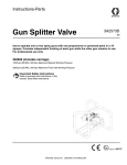
Instructions
™
XTR
Airless Spray Gun
Part No. 233889, Series A
Heavy Duty RAC tip guard, 519 SwitchTip™
Part No. 234032, Series A
Standard (nonreversing) Dripless™ tip guard, 519 flat tip
7250 psi (50 MPa, 500 bar) Maximum Working Pressure
Read warnings and instructions.
Graco Inc. P.O. Box 1441 Minneapolis, MN 55440-1441
Copyright 2002, Graco Inc. is registered to I.S. EN ISO 9001
309523D
Contents
Contents
Manual Conventions . . . . . . . . . . . . . . . . . . . . . . . .
Warning . . . . . . . . . . . . . . . . . . . . . . . . . . . . . . . . . . .
System Requirements . . . . . . . . . . . . . . . . . . . . . . .
Grounding . . . . . . . . . . . . . . . . . . . . . . . . . . . . . . . .
Gun Trigger Safety . . . . . . . . . . . . . . . . . . . . . . . . . .
Pressure Relief Procedure . . . . . . . . . . . . . . . . . . .
Operating Gun . . . . . . . . . . . . . . . . . . . . . . . . . . . . .
Maintenance . . . . . . . . . . . . . . . . . . . . . . . . . . . . . . .
2
3
4
5
5
6
7
9
Flushing . . . . . . . . . . . . . . . . . . . . . . . . . . . . . . . . . 11
Repair . . . . . . . . . . . . . . . . . . . . . . . . . . . . . . . . . . . 12
Parts . . . . . . . . . . . . . . . . . . . . . . . . . . . . . . . . . . . . 16
Technical Data . . . . . . . . . . . . . . . . . . . . . . . . . . . . 19
Dimensions . . . . . . . . . . . . . . . . . . . . . . . . . . . . . . . 19
Graco Standard Warranty . . . . . . . . . . . . . . . . . . . 20
Graco Phone Numbers . . . . . . . . . . . . . . . . . . . . . 20
Manual Conventions
Warning
WARNING
A warning alerts you to possible serious injury or
death if you do not follow instructions.
Symbols, such as fire and explosion (shown), alert you
to a specific hazard and direct you to read the indicated hazard warnings on pages 3-4.
2
Caution
CAUTION
A caution alerts you to possible equipment damage or
destruction if you do not follow instructions.
Note
A note indicates additional helpful information.
309523D
Warning
WARNING
INJECTION HAZARD
High-pressure fluid from gun, hose leaks, or ruptured components will pierce skin. This may look like just
a cut, but it is a serious injury that can result in amputation. Get immediate medical attention.
•
Do not point the gun at anyone or at any part of the body.
•
Do not put your hand or fingers over the gun fluid nozzle.
•
Do not stop or deflect leaks with your hand, body, glove, or rag.
•
Do not “blow back” fluid; this is not an air spray system.
•
Follow Pressure Relief Procedure, page 6, when you stop spraying and before cleaning, checking,
or servicing equipment.
•
Use lowest possible pressure when flushing, priming, or troubleshooting.
•
Never spray without tip guard and trigger guard installed.
•
Engage trigger lock when not spraying.
•
Tighten all fluid connections before operating the equipment.
•
Check hoses, tubes, and couplings daily. Replace worn or damaged parts immediately. High pressure hose cannot be recoupled; replace the entire hose.
FIRE AND EXPLOSION HAZARD
Solvent and paint fumes in work area can ignite or explode. To help prevent fire and explosion:
•
Use equipment only in well ventilated area.
•
Eliminate all ignition sources, such as pilot lights, cigarettes and plastic drop cloths (potential static
arc).
•
Do not plug or unplug power cords or turn lights on or off when flammable fumes are present.
•
Keep the work area free of debris, including solvent, rags, and gasoline.
•
Ground equipment and conductive objects. See Grounding, page 5.
•
Hold gun firmly to side of grounded pail when triggering into pail.
•
Use only grounded hoses.
•
If there is static sparking or you feel a shock, stop operation immediately. Do not use equipment
until you identify and correct the problem.
EQUIPMENT MISUSE HAZARD
Misuse can cause serious injury or death.
309523D
•
For professional use only.
•
Use equipment only for its intended purpose. Call your Graco distributor for information.
•
Read manuals, warnings, tags, and labels before operating equipment. Follow instructions.
•
Check equipment daily. Repair or replace worn or damaged parts immediately.
•
Do not alter or modify equipment. Use only Graco parts and accessories.
•
Do not exceed the maximum working pressure or temperature rating of the lowest rated system
component. See Technical Data in all equipment manuals.
•
Use fluids and solvents that are compatible with equipment wetted parts. See Technical Data in all
equipment manuals. Read fluid and solvent manufacturer’s warnings.
•
Route hoses and cables away from traffic areas, sharp edges, moving parts, and hot surfaces.
•
Do not use hoses to pull equipment.
•
Comply with all applicable safety regulations.
3
System Requirements
WARNING
BURN HAZARD
This equipment is used with heated fluid, which can cause equipment surfaces to become very hot. To
avoid severe burns:
• Do not touch hot fluid or equipment.
•
Allow equipment to cool completely before touching it.
•
Wear gloves if fluid temperature exceeds 110° F (43° C).
TOXIC FLUID OR FUMES HAZARD
Toxic fluids or fumes can cause serious injury or death if splashed in the eyes or on skin, inhaled, or
swallowed.
•
Read Material Safety Data Sheet (MSDS) to know the specific hazards of the fluids you are using.
•
Store hazardous fluid in approved containers, and dispose of it according to applicable guidelines.
PERSONAL PROTECTIVE EQUIPMENT
You must wear proper protective equipment when operating, servicing, or when in the operating area of
the equipment to help protect you from serious injury, including eye injury; inhalation of toxic fumes, and
hearing loss. This equipment includes but is not limited to:
•
Protective eyewear
•
Gloves, clothing, and respirator as recommended by the fluid and solvent manufacturer
•
Hearing protection
RECOIL HAZARD
The gun can recoil when triggered at very high pressure. If unprepared, this could force your hand back
or cause you to fall and injure yourself. Be sure you have firm footing and hold the gun securely.
System Requirements
•
4
Install a bleed-type master air valve on a pneumatic
pump air supply line to relieve air trapped between
this valve and the pump after air regulator is shut off.
Trapped air can cause the pump to cycle unexpectedly.
•
Install a fluid drain valve between the pump and gun
to relieve pressure in displacement pump, hose, and
gun. Triggering gun to relieve pressure may not be
sufficient. See Pressure Relief Procedure, page 6.
309523D
Grounding
Grounding
WARNING
•
Read warnings, page 3.
Solvent flushing pails: follow local code. Use only
conductive metal pails placed on a grounded surface.
Do not place pail on a nonconductive surface, such
as paper or cardboard, which interrupts grounding
continuity.
Check your local electrical code and pump/sprayer manual for detailed grounding instructions.
•
Spray gun: ground through connection to a
grounded fluid hose and pump/sprayer.
•
Fluid hose: use only grounded hoses.
•
Fluid supply container: follow local code.
•
Object being sprayed: follow local code.
Ti1102 1
•
To maintain grounding continuity when flushing
or relieving pressure: hold metal part of gun firmly
to side of grounded metal pail, then trigger gun.
Gun Trigger Safety
WARNING
To engage trigger lock: turn it to position A. If engaged,
gun will not trigger. Engage trigger lock whenever you
stop spraying to avoid accidental triggering.
Read warnings, page 3.
Wallet-sized warning card with important injection
treatment information is included with the gun.
Additional cards are available at no charge. Provide a card to all operators.
A
Ti1950A
To disengage trigger lock: turn it to position B.
B
Ti1949A
309523D
5
Pressure Relief Procedure
Pressure Relief Procedure
WARNING
5.
Engage trigger lock.
6.
Open fluid drain valve; have a container ready to
catch drainage. Leave drain valve open until you
start spraying again.
7.
If you suspect that pressure is not fully relieved
because:
Read warnings, page 3.
1.
2.
3.
Engage trigger lock.
Shut off pump. Close bleed-type master air valve
(pneumatic pumps only).
Disengage trigger lock.
•
Spray tip is clogged
SwitchTip: Follow procedure on page 10.
Flat Tip: Very slowly loosen tip guard retaining
nut and relieve pressure gradually then loosen
completely. Clear tip.
•
4.
Hold a metal part of the gun firmly to a grounded
metal pail. Trigger gun to relieve pressure.
Hose is clogged
Slowly loosen hose end coupling and relieve
pressure gradually. Clean hose obstruction.
T12178A
6
309523D
Operating Gun
Operating Gun
Strain the fluid if it contains particles that could
clog fluid tip.
1.
Connect a grounded fluid hose to the gun.
2.
Without spray tip installed, flush pump as
instructed in pump manual. Use lowest pressure
possible. Be sure you have a firm footing and hold
gun securely.
5.
Install GHD RAC spray tip and tip guard as
instructed in the enclosed GHD RAC tip instructions. See Adjusting Spray Pattern, page 8, for
information on positioning for a vertical or horizontal pattern.
6.
Start pump and spray onto test paper.
a.
Adjust fluid pressure until spray is completely
atomized. Use lowest pressure possible;
higher pressure may not improve spray pattern and causes premature tip and pump
wear.
b.
If adjusting pressure does not give a good
spray pattern, follow Pressure Relief Procedure, page 6, then try another tip size.
Solvent
3.
Prime system with material.
Paint
4.
Follow Pressure Relief Procedure, page 6.
Engage trigger lock.
7.
309523D
Trigger gun full-open or full-close. Hold gun at right
angles to work surface. Do not swing gun in an
arc. Practice to find the best length and speed of
stroke.
7
Operating Gun
Adjusting Spray Pattern
3.
Spray Pattern Size
For a vertical pattern, turn tip guard to position E.
For a horizontal pattern turn to position D.
D
E
The spray tip orifice and spray angle determine pattern
coverage and size. When you need more coverage, use
a larger spray tip rather than increasing fluid pressure.
Spray Pattern Direction
TI1951A
1.
Follow Pressure Relief Procedure, page 6.
Engage trigger lock.
4.
Tighten nut (C).
C
TI1951A
2.
Loosen tip guard retaining nut (C).
C
TI1951A
8
309523D
Maintenance
Maintenance
Cleaning Spray Tip and Tip Guard
WARNING
1.
Follow Pressure Relief Procedure, page 6.
Engage trigger lock.
2.
Clean spray tip with a solvent-soaked brush.
Read warnings, page 3.
•
•
CAUTION
To avoid ruining packings, do not soak entire gun in
solvent.
Never hang gun by the tip guard. Damaging tip
guard edges causes paint to collect there.
309523D
•
Clean front of tip frequently to reduce fluid
buildup.
•
Clean tip and tip guard at end of each work
day.
9
Maintenance
If RAC Spray Tip Clogs
7.
WARNING
Rotate RAC tip handle (G) to spraying position
(arrow points forward).
Read warnings, page 3.
1.
2.
3.
If spray tip clogs while spraying, stop spraying
immediately.
G
8.
Engage trigger lock.
If tip is still clogged:
a.
Engage trigger lock.
b.
Shut off sprayer and disconnect power
source.
c.
Open fluid drain valve to relieve pressure.
d.
Remove and clean GHD RAC spray tip.
Rotate RAC tip handle back 180° (arrow points
back).
TI1952A
4.
5.
6.
10
Disengage trigger lock.
To remove clog, trigger gun into a pail or onto the
ground.
Engage trigger lock.
309523D
Flushing
Flushing
WARNING
4.
Start pump at its lowest pressure.
5.
Disengage trigger lock, then trigger gun into the
paint pail. When solvent appears, release trigger.
6.
Trigger gun into solvent pail. Circulate fluid until
system is thoroughly flushed.
7.
Follow Pressure Relief Procedure, page 6.
Engage trigger lock.
Read warnings, page 3.
Flush pump and gun before fluid can dry in it. If available, use flushing procedure provided in your pump or
sprayer manual instead of this procedure.
1.
Follow Pressure Relief Procedure, page 6.
Engage trigger lock.
T12178A
2.
3.
Remove tip guard and spray tip. Clean with solvent. See page 9.
Put the pump intake in a grounded pail of compatible solvent.
T12178A
309523D
11
Repair
Repair
Repair Kit 245876 is available. Parts included with
the kit are marked with *.
5.
Disassembly
1.
2.
Holding needle with tool (A*), remove needle
retainer (8).
A*
Follow Pressure Relief Procedure, page 6.
Engage trigger lock.
8
Disconnect fluid hose. Remove tip and tip guard
(17).
T12188A
17
6.
Pull needle (3*) out the front of the gun.
3*
3.
Using a wrench, remove cap (10) with spring (9)
(releases spring tension on needle).
T12183A
7.
10
Using a socket wrench, remove seal retainer (4*)
from the back of the gun. Use a pick to remove
gasket (11*).
9
T12180A
4*
11*
4.
Remove valve seat (2*) and gasket (12*).
12*
2*
T12186A
8.
Clean and replace parts as needed.
T12181A
12
309523D
Repair
Assembly
If you need to remove trigger
1.
Using a wrench, remove lock nut (13) from trigger
stud (14).
To avoid losing parts, be ready for two actuator
pins (6) to fall out of gun body (1) when trigger (5)
is removed.
2.
Slide trigger stud (14) out of gun body, and remove
trigger (5).
3.
Install trigger in reverse order of disassembly.
Grease actuator pins (6) and trigger stud (14).
14
Use clean, petroleum jelly where grease is indicated.
1.
Press a new gasket (11*) into gun body. Lightly
grease seal retainer (4*) and install. Torque to
48-72 in-lbs (5-8 N•m).
4*
11*
1
T12186A
2.
5
13
Lightly grease needle (3*), and install it into the
front of the gun, pressing needle through seal
retainer.
6
3*
T12186A
T12187B
3.
Apply light-strength Loctite™ to needle threads.
Holding needle with tool (A*), install needle
retainer (8). Tighten until it bottoms out.
A*
8
T12188A
- continued -
309523D
13
Repair
4.
Lightly grease valve seat (2*) threads. Squeeze
trigger to retract needle and install gasket (12*)
and valve seat (2*). Torque valve seat to 26-32
ft-lbs (35-43 N•m).
2.
Start and prime the pump.
3.
Disengage trigger lock and trigger gun into a waste
container for a short time.
4.
Release trigger; the gun should immediately stop
spraying and there should not be any leaks.
12*
2*
T12181A
5.
Grease and install spring (9) and cap (10). Tighten
cap to 10-13 ft-lbs (8-10 N•m).
10
9
If there is a problem, follow Pressure Relief Procedure on page 6, engage trigger lock, and disconnect fluid hose.
16
T12180A
Check through Assembly procedure and correct
problem.
If fluid inlet fitting (16) is removed, to reinstall,
apply sealant to threads and torque to 26-32 ft-lbs
(35-43 N•m).
Test gun before using
1.
14
5.
Install tip and tip guard before regular use.
Engage trigger lock. Connect fluid hose to gun.
309523D
Repair
309523D
15
Parts
Parts
Part No. 233889, Series A
Part No. 234032, Series A
Heavy Duty RAC tip guard, 519 SwitchTip™
Standard (nonreversing) Dripless™ tip guard, 519 flat tip
11*
1
18c†
17c†
18d†
4*
8
14
17b†
18b★ 17a†
10
9
3*
6
12*
2*
18a★
25
19
18
13
17
26
15
16
5
T12174B
16
309523D
Parts
Part No. 233889, Series A
Heavy Duty RAC tip guard, 519 SwitchTip™
Ref.
No.
Part No. Description
1
2*
3*
4*
5
6
8
9
10
11*
12*
13
14
15
16
15A858
–
–
–
245857
15A863
15A865
117350
15A864
–
156766
105334
177538
15A861
15A862
GUN BODY
VALVE SEAT
NEEDLE
SEAL RETAINER ASSEMBLY
TRIGGER
PIN
RETAINER
SPRING
CAP
GASKET
GASKET
LOCKNUT; M4 x 0.7
STUD
TRIGGER GUARD
FLUID FITTING, 1/4 npsm x 1/2
UNEF
17
245994 GHD RAC TIP GUARD; Includes
items 17a-17c
17a†
–
• TIP GUARD
17b†
–
• NUT
Qty.
1
1
1
1
1
2
1
1
1
1
1
1
1
1
1
1
Ref.
No.
Part No. Description
Qty.
17c†
–
• HOUSING
18
GHD519 SwitchTip, 519 size; Includes items
18a-18d
–
• SwitchTip
18a★
18b★
–
• SCREW
18c†
–
• SEAL
18d†
–
• GASKET
19
15B650 SCREWS, 6-32 UNC-2A
22▲ 222385 WARNING CARD
23▲ 187346 WARNING TAG
26
15B875 SEAL
1
1
1
1
1
1
2
1
1
1
*
Parts included in Repair Kit 245876, purchased separately. Installation tool included.
†
Parts not available separately. Order kit 245994 (see kit
instructions 406554).
★
Parts not available separately.
▲
Replacement Danger and Warning labels, tags, and cards
are available at no cost.
1
1
Part No. 234032, Series A
Standard (nonreversing) Dripless™ tip guard, 519 flat tip
Ref.
No.
Part No. Description
1
2*
3*
4*
5
6
8
9
10
11*
12*
13
14
15A858
–
–
–
246298
15A863
15A865
117350
15A864
–
156766
105334
177538
309523D
GUN BODY
VALVE SEAT
NEEDLE
SEAL RETAINER ASSEMBLY
TRIGGER
PIN
RETAINER
SPRING
CAP
GASKET
GASKET
LOCKNUT; M4 x 0.7
STUD
Qty.
1
1
1
1
1
2
1
1
1
1
1
1
1
Ref.
No.
15
16
17
18
19
22▲
23▲
25
26
Part No. Description
Qty.
15A861 TRIGGER GUARD
15A862 FLUID FITTING, 1/4 npsm x 1/2
UNEF
220222 TIP GUARD
163519 SPRAY TIP, 519 size
15B650 SCREWS, 6-32 UNC-2A
222385 WARNING CARD
187346 WARNING TAG
166969 TIP GASKET
15B875 SEAL
1
1
1
1
2
1
1
1
1
*
Parts included in Repair Kit 245876, purchased separately. Installation tool included.
▲
Replacement Danger and Warning labels, tags, and cards
are available at no cost.
17
Parts
Accessories
Part No. 245878: 2-Finger Trigger Kit
Front Extension: 7/8-14 UNF-2B with RAC 5 tip guard
and tip
Part No. 246294:10” (0.25 m)
Part No. 246295:15” (0.4 m)
Part No. 246296: 18” (0.5 m)
Part No. 236987: Inlet Swivel
1/4 npsm
Part No. 246297: 180° Spray Nozzle
7/8-14 UNC-2B
Part No. 246291: Gun Filter Swivel
1/4 npsm (not shown)
Part No. 194744: Packing Repair Tool
Included in Repair Kit 245876
24
18
194744 TOOL, packing repair
1
309523D
Technical Data
Technical Data
Maximum Working Pressure. . . . . . . . . . . . . . . . . . . . . . .
Fluid Orifice. . . . . . . . . . . . . . . . . . . . . . . . . . . . . . . . . . . .
Fluid Inlet . . . . . . . . . . . . . . . . . . . . . . . . . . . . . . . . . . . . .
Fluid Tube Inside Diameter . . . . . . . . . . . . . . . . . . . . . . . .
Maximum Fluid Temperature . . . . . . . . . . . . . . . . . . . . . .
Sound Pressure . . . . . . . . . . . . . . . . . . . . . . . . . . . . . . . .
Sound Power. . . . . . . . . . . . . . . . . . . . . . . . . . . . . . . . . . .
7250 psi (50 MPa, 500 bar)
0.090" (2.3 mm)
1/4 npsm(m)
0.25” (6.4 mm)
160°F (71°C)
103 dB(A)*
111.6 dB(A)*
stainless steel, polyethylene, nylon, polypropylene, acetal,
Wetted Parts . . . . . . . . . . . . . . . . . . . . . . . . . . . . . . . . . . .
carbide, plated steel
*Results are maximum readings taken at 6000 psi (41 MPa, 414 bar), with HD427 tip, using water. Sound power level
was tested to ISO 3744-1981.
Dimensions
Weight (including tip and tip guard) . . . . . . . . . . . . . . . . . 26 oz (745 g)
Length. . . . . . . . . . . . . . . . . . . . . . . . . . . . . . . . . . . . . . . . 5” (127 mm)
Height . . . . . . . . . . . . . . . . . . . . . . . . . . . . . . . . . . . . . . . . 8” (203 mm)
309523D
19
Graco Standard Warranty
Graco warrants all equipment referenced in this document which is manufactured by Graco and bearing its name to be free from defects in material
and workmanship on the date of sale by an authorized Graco distributor. With the exception of any special, extended, or limited warranty published
by Graco, Graco will, for a period of twelve months from the date of sale, repair or replace any part of the equipment determined by Graco to be
defective. This warranty applies only when the equipment is installed, operated and maintained in accordance with Graco’s written
recommendations.
This warranty does not cover, and Graco shall not be liable for general wear and tear, or any malfunction, damage or wear caused by faulty
installation, misapplication, abrasion, corrosion, inadequate or improper maintenance, negligence, accident, tampering, or substitution of
non-Graco component parts. Nor shall Graco be liable for malfunction, damage or wear caused by the incompatibility of Graco equipment with
structures, accessories, equipment or materials not supplied by Graco, or the improper design, manufacture, installation, operation or maintenance
of structures, accessories, equipment or materials not supplied by Graco.
This warranty is conditioned upon the prepaid return of the equipment claimed to be defective to an authorized Graco distributor for verification of
the claimed defect. If the claimed defect is verified, Graco will repair or replace free of charge any defective parts. The equipment will be returned
to the original purchaser transportation prepaid. If inspection of the equipment does not disclose any defect in material or workmanship, repairs will
be made at a reasonable charge, which charges may include the costs of parts, labor, and transportation.
THIS WARRANTY IS EXCLUSIVE, AND IS IN LIEU OF ANY OTHER WARRANTIES, EXPRESS OR IMPLIED, INCLUDING BUT NOT LIMITED
TO WARRANTY OF MERCHANTABILITY OR WARRANTY OF FITNESS FOR A PARTICULAR PURPOSE.
Graco’s sole obligation and buyer’s sole remedy for any breach of warranty shall be as set forth above. The buyer agrees that no other remedy
(including, but not limited to, incidental or consequential damages for lost profits, lost sales, injury to person or property, or any other incidental or
consequential loss) shall be available. Any action for breach of warranty must be brought within two (2) years of the date of sale.
GRACO MAKES NO WARRANTY, AND DISCLAIMS ALL IMPLIED WARRANTIES OF MERCHANTABILITY AND FITNESS FOR A
PARTICULAR PURPOSE, IN CONNECTION WITH ACCESSORIES, EQUIPMENT, MATERIALS OR COMPONENTS SOLD BUT NOT
MANUFACTURED BY GRACO. These items sold, but not manufactured by Graco (such as electric motors, switches, hose, etc.), are subject to the
warranty, if any, of their manufacturer. Graco will provide purchaser with reasonable assistance in making any claim for breach of these warranties.
In no event will Graco be liable for indirect, incidental, special or consequential damages resulting from Graco supplying equipment hereunder, or
the furnishing, performance, or use of any products or other goods sold hereto, whether due to a breach of contract, breach of warranty, the
negligence of Graco, or otherwise.
FOR GRACO CANADA CUSTOMERS
The Parties acknowledge that they have required that the present document, as well as all documents, notices and legal proceedings entered into,
given or instituted pursuant hereto or relating directly or indirectly hereto, be drawn up in English. Les parties reconnaissent avoir convenu que la
rédaction du présente document sera en Anglais, ainsi que tous documents, avis et procédures judiciaires exécutés, donnés ou intentés, à la suite
de ou en rapport, directement ou indirectement, avec les procédures concernées.
Graco Phone Numbers
TO PLACE AN ORDER, contact your Graco distributor or call to identify the nearest distributor.
Phone: 612-623-6921 or Toll Free: 1-800-367-4023, Fax: 612-378-3505
All written and visual data contained in this document reflects the latest product information available at the time of publication.
Graco reserves the right to make changes at any time without notice.
Sales Offices: Minneapolis, Detroit
International Offices: Belgium, Korea, Hong Kong, Japan
GRACO INC. P.O. BOX 1441 MINNEAPOLIS, MN 55440-1441
www.graco.com
Printed in USA 309523D
8/2002, Revised 10/2002