1
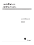
Installation
Instructions
Refrigerator
Models 15, 16, 17, 18
Questions? Call 800.GE.CARES (800.432.2737) or Visit our Website at: www.GEAppliances.com
In Canada, call 1.800.361.3400 or Visit our Website at: www.geappliances.ca
BEFORE YOU BEGIN
CLEARANCES
Read these instructions completely and carefully.
Allow the following clearances for ease of installation,
proper air circulation and plumbing and electrical
connections.
•
IMPORTANT – Save these
instructions for local inspector’s use.
•
IMPORTANT – Observe all
•
Note to Installer – Be sure to leave these
•
Note to Consumer – Keep these instructions
• Sides 3/4″ (19 mm)
• Top 1″ (25 mm)
• Back 1″ (25 mm)
governing codes and ordinances.
instructions with the Consumer.
•
•
•
•
ROLLERS AND LEVELING LEGS
for future reference.
Skill level – Installation of this appliance requires
basic mechanical skills.
Completion time – Refrigerator Installation
15 minutes
Reversing the Door Swing
1 hour
Proper installation is the responsibility of the
installer.
Product failure due to improper installation is not
covered under the Warranty.
Leveling legs near each front corner of the refrigerator
are adjustable. They firmly position the refrigerator
and prevent it from moving when the doors are
opened. Leveling legs should be set so the front of the
refrigerator is raised just enough that the doors close
easily when opened about halfway.
Turn the leveling legs clockwise to raise the
refrigerator, counterclockwise to lower it.
Rollers next to the leveling legs allow you to move the
refrigerator away from the wall for cleaning.
Turn the legs counterclockwise until the weight of the
refrigerator is transferred from them to the rollers.
After rolling the refrigerator back into place, turn the
legs clockwise until the legs again bear the weight of
the refrigerator.
WATER SUPPLY TO THE ICEMAKER
(on some models)
If the refrigerator has an icemaker, it will have to be
connected to a cold water line. A water supply kit
(containing copper tubing, shutoff valve, fittings and
instructions) is available at extra cost from your dealer,
by visiting our Website at www.GEAppliances.com (in
Canada at www.geappliances.ca) or from Parts and
Accessories, 800.626.2002 (in Canada 1.888.261.3055).
REFRIGERATOR LOCATION
• Do not install the refrigerator where the temperature
will go below 60°F (16°C) because it will not run often
enough to maintain proper temperatures.
• Install it on a floor strong enough to support it fully
loaded.
12
Installation Instructions
1 INSTALLING THE WATER LINE
BEFORE YOU BEGIN
(ON SOME MODELS)
WHAT YOU WILL NEED
Recommended copper water supply kits are WX8X2,
WX8X3 or WX8X4, depending on the amount of
tubing you need. Approved plastic water supply lines
are GE SmartConnect™ Refrigerator Tubing
(WX08X10002, WX08X10006, WX08X10015 and
WX08X10025).
When connecting your refrigerator to a GE Reverse
Osmosis Water System, the only approved installation
is with a GE RVKit. For other reverse osmosis water
systems, follow the manufacturer’s recommendations.
• Copper or GE SmartConnect™ Refrigerator Tubing
kit, 1/4″ outer diameter to connect the refrigerator
to the water supply. If using copper, be sure both
ends of the tubing are cut square.
This water line installation is not warranted by the
refrigerator or icemaker manufacturer. Follow these
instructions carefully to minimize the risk of expensive
water damage.
To determine how much tubing you need: measure
the distance from the water valve on the back of the
refrigerator to the water supply pipe. Then add 8′
(2.4 m). Be sure there is sufficient extra tubing
(about 8′ [2.4 m] coiled into 3 turns of about 10″
[25 cm] diameter) to allow the refrigerator to move
out from the wall after installation.
Water hammer (water banging in the pipes) in house
plumbing can cause damage to refrigerator parts and
lead to water leakage or flooding. Call a qualified
plumber to correct water hammer before installing
the water supply line to the refrigerator.
GE SmartConnect™ Refrigerator Tubing Kits are
available in the following lengths:
To prevent burns and product damage, do not hook
up the water line to the hot water line.
2′ (0.6 m)
6′ (1.8 m)
15′ (4.6 m)
25′ (7.6 m)
If you use your refrigerator before connecting the
water line, make sure the icemaker power switch is
in the O (off) position (on power switch models) or
the feeler arm is in the STOP (up) position (on feeler
arm models).
– WX08X10002
– WX08X10006
– WX08X10015
– WX08X10025
Be sure that the kit you select allows at least 8′ (2.4 m)
as described above.
Do not install the icemaker tubing in areas where
temperatures fall below freezing.
NOTE: The only GE approved plastic tubing is that
supplied in GE SmartConnect™ Refrigerator Tubing
kits. Do not use any other plastic water supply line
because the line is under pressure at all times. Certain
types of plastic will crack or rupture with age and
cause water damage to your home.
When using any electrical device (such as a power
drill) during installation, be sure the device is double
insulated or grounded in a manner to prevent the
hazard of electric shock, or is battery powered.
All installations must be in accordance with local
plumbing code requirements.
13
Installation Instructions
1 INSTALLING THE WATER LINE
(CONT.)
Install the shutoff valve on the nearest frequently used
drinking water line.
WHAT YOU WILL NEED (CONT.)
• A GE water supply kit (containing tubing, shutoff
valve and fittings listed below) is available at extra
cost from your dealer or from Parts and Accessories,
800.626.2002.
• A cold water supply. The water pressure must be
between 20 and 120 p.s.i. (1.4–8.1 bar).
1 SHUT OFF THE MAIN WATER
SUPPLY
Turn on the nearest faucet long enough to clear
the line of water.
2 CHOOSE THE VALVE LOCATION
Choose a location for the valve that is easily
accessible. It is best to connect into the side of
a vertical water pipe. When it is necessary to
connect into a horizontal water pipe, make the
connection to the top or side, rather than at the
bottom, to avoid drawing off any sediment from
the water pipe.
• Power drill.
• 1/2″ or adjustable wrench.
• Straight and Phillips blade screwdriver.
• Two 1/4 ″ outer diameter compression nuts and
2 ferrules (sleeves)—to connect the copper tubing
to the shutoff valve and the refrigerator water valve.
OR
• If you are using a GE SmartConnect™ Refrigerator
Tubing kit, the necessary fittings are preassembled
to the tubing.
3 DRILL THE HOLE FOR THE VALVE
Drill a 1/4″ hole in the water pipe (even if using
a self-piercing valve) using a sharp bit. Remove any
burrs resulting from drilling the hole in the pipe.
Take care not to allow water to drain into the drill.
Failure to drill a 1/4″ hole may result in reduced
ice production or smaller cubes.
• If your existing copper water line has a flared fitting
at the end, you will need an adapter (available at
plumbing supply stores) to connect the water line to
the refrigerator OR you can cut off the flared fitting
with a tube cutter and then use a compression
fitting. Do not cut formed end from GE
SmartConnect™ Refrigerator tubing.
• Shutoff valve to connect to the cold water line.
The shutoff valve should have a water inlet with a
minimum inside diameter of 5/32″ at the point of
connection to the COLD WATER LINE. Saddle-type
shutoff valves are included in many water supply kits.
Before purchasing, make sure a saddle-type valve
complies with your local plumbing codes.
14
Installation Instructions
4 FASTEN THE SHUTOFF VALVE
7 CONNECT THE TUBING
TO THE VALVE
Fasten the shutoff valve to the cold water pipe with
the pipe clamp.
Place the compression nut and ferrule (sleeve)
for copper tubing onto the end of the tubing and
connect it to the shutoff valve.
Pipe Clamp
Make sure the tubing is fully inserted into the
valve. Tighten the compression nut securely.
Saddle-Type
Shutoff Valve
For plastic tubing from a GE SmartConnect™
Refrigerator Tubing kit, insert the molded end
of the tubing into the shutoff valve and tighten
compression nut until it is hand tight, then tighten
one additional turn with a wrench. Overtightening
may cause leaks.
Vertical Cold
Water Pipe
NOTE: Commonwealth of Massachusetts Plumbing
Codes 248CMR shall be adhered to. Saddle valves
are illegal and use is not permitted in Massachusetts.
Consult with your licensed plumber.
Compression
Nut
Saddle-Type
Shutoff Valve
SmartConnect™
Tubing
5 TIGHTEN THE PIPE CLAMP
Tighten the clamp screws until the sealing washer
begins to swell.
Packing Nut
NOTE: Do not overtighten or you may crush the
tubing.
Outlet Valve
NOTE: Commonwealth of Massachusetts Plumbing
Codes 248CMR shall be adhered to. Saddle valves
are illegal and use is not permitted in Massachusetts.
Consult with your licensed plumber.
Washer
Pipe Clamp
Ferrule (sleeve)
Inlet End
Clamp Screw
8 FLUSH OUT THE TUBING
Turn the main water supply on and flush out the
tubing until the water is clear.
Shut the water off at the water valve after about
one quart (1 liter) of water has been flushed
through the tubing.
6 ROUTE THE TUBING
Route the tubing between the cold water line and
the refrigerator.
Route the tubing through a hole drilled in the wall
or floor (behind the refrigerator or adjacent base
cabinet) as close to the wall as possible.
NOTE: Be sure there is sufficient extra tubing
(about 8 feet [244 cm] coiled into 3 turns of about
10 ″ [25 cm] diameter) to allow the refrigerator to
move out from the wall after installation.
15
Installation Instructions
1 INSTALLING THE WATER LINE
9 CONNECT THE TUBING TO THE
(CONT.)
9 CONNECT THE TUBING TO THE
REFRIGERATOR (CONT.)
REFRIGERATOR
Fasten the tubing into the clamp provided to
hold it in a vertical position. You may need to
pry open the clamp.
NOTES:
• Before making the connection to the refrigerator,
be sure the refrigerator power cord is not plugged
into the wall outlet.
Tubing Clamp
1/4″ Copper
Tubing
• We recommend installing a water filter if your
water supply has sand or particles that could clog
the screen of the refrigerator’s water valve. Install
it in the water line near the refrigerator. If using
GE SmartConnect™ Refrigerator Tubing kit,
you will need an additional tube (WX08X10002)
to connect the filter. Do not cut plastic tube to
install filter.
1/4″ Compression
Nut
Ferrule
(sleeve)
Refrigerator
Connection
Remove the access cover.
SmartConnect™
Tubing
Reattach the access cover.
Remove the plastic flexible cap from the water
valve (refrigerator connection).
10 TURN THE WATER ON AT THE
SHUTOFF VALVE
Tighten any connections that leak.
Place the compression nut and ferrule (sleeve)
onto the end of the tubing as shown. On GE
SmartConnect™ Refrigerator Tubing kit,
the nuts are already assembled to the tubing.
Insert the end of the tubing into the water valve
connection as far as possible. While holding the
tubing, tighten the fitting.
For plastic tubing from a GE SmartConnect™
Refrigerator Tubing kit, insert the molded end
of the tubing into the shutoff valve and tighten
compression nut until it is hand tight, then
tighten one additional turn with a wrench.
Overtightening may cause leaks.
16
Installation Instructions
11 PLUG IN THE REFRIGERATOR
12 START THE ICEMAKER
On power switch models, set the icemaker power
switch to the l (on) position. On feeler arm models,
move the feeler arm to the ON (down) position. The
icemaker will not begin to operate until it reaches
its operating temperature of 15°F (–9°C) or below.
It will then begin operation automatically.
Arrange the coil of tubing so that it does not vibrate
against the back of the refrigerator or against the
wall. Push the refrigerator back to the wall.
Power
switch
Power switch model
Feeler Arm in the
STOP (up) position
Feeler Arm in
the ON (down) position
Feeler arm model
NOTE: In lower water pressure conditions, the
water valve may turn on up to 3 times to deliver
enough water to the icemaker.
2 REVERSING THE DOOR SWING
TOOLS REQUIRED
IMPORTANT NOTES
When reversing the door swing:
• Read the instructions all the way through before
starting.
• Handle parts carefully to avoid scratching paint.
• Set screws down by their related parts to avoid using
them in the wrong places.
• Provide a non-scratching work surface for
the doors.
IMPORTANT: Once you begin, do not move the
cabinet until door-swing reversal is completed.
These instructions are for changing the hinges from
the right side to the left side—if you ever want to change
the hinges back to the right side, follow these same
instructions and reverse all references to left and right.
Phillips screwdriver
5/16″ hex-head
socket driver
Putty knife or thin-blade
screwdriver
17
Masking tape
T20 or T25 Torxdriver,
whichever your model
requires
5/16″ open-end
wrench