1
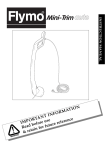
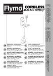
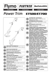
POWER TRIM
600 HD
Original Instructions
TIO
A
M
R
N
FO
N
I
ANT
T
R
nce
e
O
s
e
P
r
u
e
f
e
M
I
efor uture re
b
d
a
Re
or f
f
n
i
ta
& re
For all customer enquiries or for replacement parts, contact:-
01325 300303
www.flymo.com
[email protected]
1
Carton Contents
Switch Handle
Steady Handle
Tube
Trimmer Head
Instruction
Manual
Guard
Electric Cable with
moulded on plug
IMPORTANT ! Please check the contents of the carton are correct BEFORE assembling your new Flymo product.
IF ANY PARTS ARE MISSING CONTACT:Husqvarna UK Ltd. Customer Service Department direct
Telephone : 01325 300303, Fax : 01325 302530
Safety
If not used properly this trimmer can be dangerous! This trimmer can cause serious injury to the operator and others, the warnings and safety instructions must be followed to ensure reasonable safety and
efficiency in using this trimmer. The operator is responsible for following the warning and safety instructions in this manual and on the trimmer.
Explanation of Symbols on the Power Trim
Warning
Read the user instructions carefully to
make sure you understand all the
controls and what they do.
360º
10m
Keep others, including children, pets and
bystanders outside the 10 metre hazard
zone. Stop the trimmer immediately if
you are approached.
General
1. This product is not intended for use by persons (including children) with reduced physical, sensory or
mental capabilities, or lack of experience and knowledge, unless they have been given supervision or
instruction concerning the use of the product by a
person responsible for their safety. Children should
be supervised to ensure that they do not play with
the product. Local regulations may restrict the age of
the operator.
2. Only use the trimmer in the manner and for the functions described in these instructions.
3. Never operate the trimmer when you are tired, ill or
under the influence of alcohol, drugs or medicine.
4. The operator or user is responsible for accidents or
hazards occurring to other people or their property.
The use of eye protection is recommended
to protect against objects thrown by the cutting line.
To avoid the possibility of electric shock, do
not use in damp or wet conditions.
Switch off! Remove plug from mains before
adjusting, cleaning or if cable is entangled or
damaged.
Warning: The cutting line continues to rotate
after the machine has been switched off.
Electrical
AVOID ACCIDENTAL STARTING. REMOVE PLUG
FROM MAINS AND KEEP FEET AWAY FROM THE
SWITCH LEVER WHEN:- CLEANING AROUND THE
INSIDE OF THE SAFETY GUARD, REMOVING OR
REFITTING SPOOL CAP, MANUALLY FEEDING OR
REPLACING NYLON LINE.
1. The British Standards Institute recommend the use
of a Residual Current Device (R.C.D.) with a tripping
current of not more than 30mA. Even with a R.C.D.
installed 100% safety cannot be guaranteed and safe
working practice must be followed at all times.
Check your R.C.D. every time you use it.
2. Before use, examine cable for damage. If there are
signs of damage or ageing, it must be replaced by
the manufacturers service agent or a similar qualified person to avoid hazard.
3. Do not use the trimmer if the electric cables are
damaged or worn.
2
4.
Immediately disconnect from the mains electricity supply if the cable is cut, or the insulation is damaged. Do
not touch the electric cable until the electrical supply
has been disconnected. Do not repair a cut or damaged cable. Replace it with a new one.
5. Your extension cable must be uncoiled, coiled cables
can overheat and reduce the efficiency of your trimmer.
6. Keep the cable clear of the cutting area and obstacles at all times.
7. Do not pull cable around sharp objects.
8. Always switch off at the mains before disconnecting
any plug, cable connector or extension cable.
9. Never pull on the cable to disconnect any of the plugs.
10. Switch off, remove plug from mains and examine electric
supply cable for damage or ageing before winding cable
for storage. Do not repair a damaged cable, replace it with
a new one. Use only Flymo replacement cable.
11. Always wind cable carefully, avoiding kinking.
12. Use only on AC mains supply voltage shown on the
product rating label.
13. Flymo trimmers are double insulated to EN60335.
Under no circumstance should an earth be connected to any part of the trimmer.
Preparation
1. While using your product always wear substantial
footwear and long trousers.
2. Before using the machine and after any impact, check
for signs of wear or damage and repair as necessary.
3. Inspect the area to be cut before each use. Remove
all objects such as stones, broken glass, nails, wire,
string etc, which can be thrown or become entangled in the trimmer head.
4. Before use, inspect the area for wildlife, especially
hedgehogs.
5. Check that the cutting head is fitted correctly.
Use
1. Use the trimmer only in daylight or good artificial light.
2. Avoid operating your trimmer in wet grass, where feasible.
3. Take care in wet grass, you may lose your footing.
4. On slopes, be extra careful of your footing and wear
non-slip footwear.
5. Do not walk backwards when trimming, you could
trip. Walk never run.
6. Keep cutting head below waist level.
7. Never operate the trimmer with damaged guards or
without guards in place.
8. Never fit metal cutting elements.
9. Keep hands and feet away from the cutting means at
all times and especially when switching on the motor.
10. Never pick up or carry a trimmer by the cable.
11. Do not lean over the trimmer guard - objects may be
thrown by the cutting line.
12. Remove the plug from the mains :
before leaving the trimmer unattended for any period;
before clearing a blockage;
before checking, cleaning or working on the appliance;
if you hit an object. Do not use your trimmer until
you are sure that the entire trimmer is in a safe operating condition;
if the trimmer starts to vibrate abnormally. Check
immediately. Excessive vibration can cause injury.
Maintenance and storage
1. Keep all nuts, bolts and screws tight to be sure the
trimmer is in safe working condition.
2. Replace worn or damaged parts for safety.
3. Only use the replacement cutting line specified for
this product.
4. Only use replacement parts and accessories recommended by Husqvarna UK Ltd..
5. After any maintenance in dealing with the cutting line,
always return the product to its normal operating position before switching on.
6. Clean unit with a dry cloth. Never use metal objects
to clean the unit.
7. Inspect and maintain the trimmer regularly. Any repairs
must be carried out by an authorised repairer.
8. Store in a cool dry place and out of reach of children.
Do not store outdoors.
Cables
IMPORTANT
Use only 1.00mm2 size cable up to 40 metres length
maximum.
Maximum rating:
1.00mm2 size cable, 10 amps 250 volts AC.
THE POWER TRIM IS SUPPLIED WITH AN ELECTRIC MAINS CABLE WIRED DIRECTLY INTO THE
PRODUCT.
1. Flymo Mains Cables and Extension Cables are
available from your local Approved Service Centre.
2. Do not wire an extension cable directly to your product
yourself. Please contact your local Approved Service
Centre for further information on the connectors and
kits available.
3. Only use extension cables specifically designed for
outdoor use.
CONNECTORS
Flymo connectors are suitable for use with 2 core cable
only. Under no circumstances should these connectors
be used for earthed products.
All Flymo connectors and cables are of splashproof construction. They are not waterproof and must not be left
outside permanently nor should they be submerged or
immersed in water. Do not let cable lay or trail through
pools of water or splashed with water from hose pipes.
MAINS PLUG REPLACEMENT
• If the plug supplied is cut off it should be destroyed. There is an electric shock hazard if a
cut off plug is inserted into a 13 amp socket.
1. No earth required. Flymo products are double insulated to EN60335 and under no circumstances
should an earth be connected to any part of the
product.
2. Ensure the mains voltage suits your product.
3. IMPORTANT!
The wires in the mains lead are coloured in accordance
with the following code:
BLUE
NEUTRAL
BROWN
LIVE
The wire which is coloured BLUE must be connected to
the Terminal which is marked with the letter ʻNʼ or
coloured BLACK. The wire which is coloured BROWN
must be connected to the Terminal which is marked with
the letter ʻLʼ or coloured RED.
4. It is important that the outer sheath is clamped correctly into the 3-pin plug.
5. If in doubt consult your local Service Repairer or
qualified electrician before the machine is used.
6. A 5 Amp fuse must be fitted to the Mains Plug.
7. The normal plug fuse and household fuse only protect the electrical equipment and are not a safeguard
against electrocution.
If your product is hard wired i.e. non-detachable
mains electric cable, a conversion kit and extension cable is available from all Approved Service
Centres which can be found in your local Yellow
Pages.
3
Assembly Instructions
A1
A2
K!
IC
K!
CL
C
LI
C
B1
B2
C
D
1
1
2
2
3
E1
E2
Assembly of Switch Handle to Tube (A1)
• Ensure that the internal cable is not twisted.
1. Insert the tube into the switch handle.
2. Push until it clicks into position.
• ENSURE THAT THE TUBE IS FULLY LOCATED BY
ATTEMPTING TO REMOVE IT.
Assembly of Trimmer Head to Tube (A2)
• Ensure that the internal cable is not twisted.
1. Insert the tube into the trimmer head.
2. Push until it clicks into position.
• ENSURE THAT THE TUBE IS FULLY LOCATED BY
ATTEMPTING TO REMOVE IT.
Safety Guard Assembly (B1) & (B2)
1. Locate the safety guard over the cutting head. Ensure the nylon line is fed through the hole in the
safety guard as illustrated in fig B1.
2. Push into location and turn safety guard in the direction illustrated in Fig B2, until a click is heard and the
safety guard is securely locked in position.
• ENSURE THE SAFETY GUARD IS SECURELY IN
PLACE BY ATTEMPTING TO TWIST GUARD.
Steady Handle Assembly (C)
1. Depress the two buttons on the sides of the switch
handle.
2. Locate the steady handle over the buttons and release the buttons.
3. Adjust the steady handle to the most comfortable operating position by depressing the buttons and moving the handle.
Height Adjustment (D)
1. Turn height adjuster (D1) in the direction indicated to
un-lock (D2).
2. Adjust the length of the tube to the most comfortable
operating position.
3. Turn height adjuster in the opposite direction to lock
(D3).
• ENSURE THAT THE TUBE IS FULLY SECURED.
Cable Restraint (E1) & (E2)
1. Form loop in mains cable and push the loop through
the slot as illustrated in picture (E1).
2. To secure, position loop over the hook and pull the
cable back through the slot as illustrated in picture
(E2).
Double Auto Feed System
F
line cutter
How the automatic line feed works (F)
1. When initially switching on the trimmer, a small length
of line is fed out.
2. A ʻclatteringʼ noise will be heard when the two nylon
lines hit the line cutter. DO NOT BE ALARMED this
is quite normal. After approximately 5 seconds the
line will be cut to the correct length and the noise will
reduce as the motor reaches full speed.
• Make sure the motor is up to speed before trimming or edging.
3. If the noise of the nylon line being cut cannot be
heard, more line will need to be fed out.
4. To feed more line, it is first necessary to to allow the
motor to stop completely, then re-start, allowing the
motor to reach full speed.
5. Repeat step 4. until you hear the lines hitting against the
cutter. (Do not repeat this procedure more than 6 times)
6. If problems are experienced with the automatic line
feed refer to Fault Finding Chart.
How to trim and edge
H
G
•
•
•
J
K
1
L
1
2
WARNING
The use of eye protection is recommended.
Do not lean over the trimmer whilst trimming or
edging, objects may be thrown by the cutting line.
Do not allow cutting head to rest on the ground.
Do not overload your trimmer.
Overloading can be avoided by making sure the
motor speed does not drop unduly.
DISCONNECT FROM THE MAINS ELECTRICITY
SUPPLY BEFORE ATTEMPTING ANY MAINTENANCE OR ADJUSTMENT.
BEFORE USE
Make sure that both lines are fed out.
Make sure motor is up to speed before trimming
or edging.
How to trim
• YOUR PRODUCT CONTAINS ELECTRONIC
SPEED CONTROL FOR YOUR SAFETY. YOUR
PRODUCT WILL START SLOWLY AND SPEED UP
WHEN YOU START CUTTING.
1. Hold as illustrated in Fig G.
2. To start, squeeze the switch lever.
3. Cut with nylon line at an angle using the tip. See Fig
H.
4. Swing trimmer in and out of the cutting area taking
small cuts (J)
5. Line is fed out automatically every time the trimmer
head stops rotating and returns to operating speed.
• Extra line can be fed out manually as described in
Manual line feed
6. To stop your trimmer release the switch lever.
How to edge
1. To convert to edging mode, depress the locking button (K1) and twist head anti-clockwise (K2). An audible "click" will confirm that the head is locked. Ensure
the button has returned to its original position.
2. Hold as illustrated in Fig G.
3. To start, squeeze the switch lever.
4. Rest the edger on the roller for extra stability and line
up the edge of the lawn with the two indicators on the
guard (L1). Edge in direction indicated in Fig L.
5. To return to trimming mode, depress the locking button and twist head clockwise. An audible "click" will
confirm that the head is locked. Ensure the button
has returned to its original position.
Manual line feed
M
manual line
feed button
To manually feed the nylon line (M)
1. If required line can be fed out manually.
2. To operate, press and release manual line feed button, whilst gently pulling on one of the lines until the
line reaches the line cutter.
3. When the required amount of line is fed out, gently
pull on the second line (there is no need to press the
manual line feed button again).
4. If the line extends past the line cutter, too much line
has been fed out.
5. If too much line is fed out, remove the spool cap and
click spool anti-clockwise until the line is at the desired
length.
Cutting Head
To remove spool cap
1. Press and hold in the two cap release latches. (N).
2. Pull cap away from the spoolholder. (N).
When refitting the spool cap
1. Keep all areas of the cap and spoolholder clean.
Failure to do so may prevent the cap being securely
located in the spoolholder.
2. Replace the cap, pressing firmly DOWN towards
the spoolholder to ensure cap is fully located.
3. Check that the cap is correctly fitted by trying to remove it without depressing the two latches.
To replace nylon line
For your convenience it is recommended you buy spool
and line complete. Nylon line only is also available. Both
are available from Husqvarna UK Ltd. stockists.
To fit spool and line complete:
1. Remove the cap.
2. Remove old spool.
3. Place spool into spoolholder.
4. Release one line from cleat (Q1).
5. Secure line into slot (P1).
6. Repeat for second line.
• Ensure spool is fully located by gently rotating it during
fitment, whilst keeping the spoolholder steady.
7. Refit the cap.
To fit nylon line only:
• Remember ! Your Flymo Trimmer is designed to use
only nylon line with a maximum diameter of 2.0mm.
Use only genuine Flymo nylon line.
1. IMPORTANT - Always wind the line onto the upper
section of the spool first.
Take approximately 5 metres of line. Insert 15mm of
line into one of the holes in the upper section of the
spool (Q) and wind line in the direction of the arrows
on the top of the spool. Leave approximately 100mm
of line unwound and place into cleat as illustrated in
figure Q1. Repeat on lower section of spool.
2. Care should be taken to ensure that the line is neatly
coiled on the spool. Failure to do so will impair the efficiency of the automatic line feed.
3. Then fit spool as described in ‘To fit spool and line
complete’, section above.
N
Cap
Cap release
latch
Spool
Spoolholder
Slot
P
P1
Q1
Q
Cleat
Maintenance
R
•
WARNING
Disconnect from the mains electricity supply, before attempting any maintenance or adjustment.
Cutting head continues to rotate after the trimmer
has been switched off. Keep fingers and hands
clear of the line cutter on leading edge of guard.
Caring for your Power Trim
After you have finished using your Flymo Power Trim follow the procedure below:
AVOID ACCIDENTAL STARTING. REMOVE PLUG
FROM MAINS AND KEEP FEET AWAY FROM THE
SWITCH LEVER WHEN: CLEANING AROUND THE INSIDE OF THE SAFETY GUARD, REMOVING OR REFITTING SPOOL CAP, MANUALLY FEEDING OR
REPLACING NYLON LINE.
1. Disconnect from the mains electricity supply.
2. Never clean your trimmer with water, cleaning fluids,
or solvents, just remove debris with a suitable tool, a
soft brush or dry cloth.
3. Using a soft brush, clean around the inside of the
safety guard, the cutting head (Fig R) and the motor
housing air vents. (Fig S)
4. Inspect the trimmer carefully, especially the parts of
the cutting head.
5. If your trimmer is damaged in any way contact your
local approved service centre.
• Never use a damaged trimmer.
6. Store in a cool, dry place and out of reach of children.
Cable Storage
1. Your mains cable can be stored on the product as illustrated in Fig T.
2. Wind cable carefully to avoid kinking.
3. To release the cable press the button and the hook
will drop down (Fig V).
4. Push cable hook fully back into position.
S
T
V
Fault Finding Chart
WARNING Disconnect from the mains electricity supply before attempting any maintenance or adjustment.
FAULT
LINE NOT FEEDING
OR
LINE TOO SHORT
OR
TRIMMER VIBRATES
CONTINUOUS CLATTERING NOISE
LINE SNAPS CONTINUOUSLY
CHECK
ACTION
Is the automatic line feed working?
No
Manually feed out line.
SEE “MANUAL LINE FEED”
Is the line fed out and visible?
Has line been removed from
cleat?
No
Remove cap and spool, free line
and re-fit spool and cap. SEE
“CUTTING HEAD”
Is the manual line feed working?
No
The line may be jammed on the
spool. Rewind line to remove
crossed loops. Check that line is in
correct section of spool.
Is the motor up to speed before
use?
No
Allow the motor to reach operating
speed before use.
Has too much line been fed out?
Yes
SEE “MANUAL LINE FEED”
Is the line cutter missing from the
safety guard?
Yes
Contact your local approved
Service Centre or Husqvarna UK
Ltd. Customer Service.
Are you using the trimmer correctly?
Is the line jamming on the spool?
IF NONE OF THE ABOVE
OR IF FAULT PERSISTS
?
Yes
Only use tip of nylon line to trim.
SEE “How to trim and edge”
Rewind the line on the spool, if
symptoms still persist, change
spool and line.
Contact Husqvarna UK Ltd. Customer Service
Telephone : 0870 609 1901
Environmental Information
•
•
Awareness of the environment must be considered
when disposing of ʻend-of-lifeʼ product.
If necessary, contact your local authority for disposal
information.
The symbol
on the product or on its packaging indicates that this product may not be treated as household
waste. Instead it shall be handed over to the applicable
collection point for the recycling of electrical and electronic equipment.
By ensuring this product is disposed of correctly, you will
help prevent potential negative consequences for the
environment and human health, which could otherwise
be caused by inappropriate waste handling of this product.
For more detailed information about recycling of this
product, please contact your local council office, your
household waste disposal service or the shop where
you purchased the product.
Guarantee & Guarantee Policy
If any part is found to be defective due to faulty manufacture
within the guarantee period, Husqvarna UK Ltd., through its Authorised Service Repairers will effect the repair or replacement to
the customer free of charge providing:
(a) The fault is reported directly to the Authorised Repairer.
(b) Proof of purchase is provided.
(c) The fault is not caused by misuse, neglect or faulty adjustment by the user.
(d) The failure has not occurred through fair wear and tear.
(e) The machine has not been serviced or repaired, taken apart
or tampered with by any person not authorised by Husqvarna
UK Ltd.
(f) The machine has not been used for hire.
(g) The machine is owned by the original purchaser.
(h) The machine has not been used commercially.
*
This guarantee is additional to, and in no way diminishes the
customers statutory rights.
Failures due to the following are not covered, therefore it is important that you read the instructions contained in this Operator's Manual and understand how to operate and maintain your machine:
Failures not covered by guarantee
*
Replacing Nylon Line.
*
Failures as a result of not reporting an initial fault.
*
Failures as a result of sudden impact.
*
Failures as a result of not using the product in accordance
with the instructions and recommendations contained in this
Operator's Manual.
*
Machines used for hire are not covered by this guarantee.
*
The following items listed are considered as wearing parts
and their life is dependent on regular maintenance and are,
therefore not normally subject to a valid warranty claim: Nylon
Line, Spool and Line, Electric Mains Cable
*
Caution!
Husqvarna UK Ltd. does not accept liability under the warranty for defects caused in whole or part, directly or indirectly
by the fitting of replacement parts or additional parts that are
not either manufactured or approved by Husqvarna UK Ltd.,
or by the machine having been modified in any way.
EC Declaration of Conformity
Husqvarna UK Ltd., Aycliffe Industrial Park
Newton Aycliffe, Co. Durham, DL5 6UP, England
Declare under our sole responsibility that the product(s);
Category............................Electric Lawn Trimmer
Type(s) ............................PTHD26
Identification of Series.......See Product Rating Label
Year of Construction..........See Product Rating Label
Conforms to the essential requirements & provisions of the following EC Directives:
98/37/EC (until 31.12.09), 2006/42/EC (from 01.01.10), 2004/108/EC, 2000/14/EC
based on the following EU harmonized standards applied:
EN60335-1, EN60335-2-91, EN786, EN50366, EN55014-1, EN61000-3-2, EN61000-3-3
The maximum A weighted sound pressure level LpA at the operatorʼs position, recorded on a sample of the above
product(s) corresponds to the Level given in the table.
The maximum hand / arm vibration weighted value measured according to EN ISO 5349 on a sample of the above
product(s) corresponds to the Value given in the table.
2000/14/EC: The Measured Sound Power LWA & Guaranteed Sound Power LWA values are according to the tabulated
figures.
Conformity Assessment Procedure............... Annex VI
Notified Body................................................. Intertek, Cleeve Road
Leatherhead, Surrey
KT22 7SB, England
Newton Aycliffe 13/11/2008
M.Bowden
Research & Development Director
Husqvarna UK Ltd.
PTHD26
Type
Width of Cut (cm)
Speed of Rotation of Cutting Device (rpm)
Power (W)
Measured Sound Power LWA (dB(A))
Guaranteed Sound Power LWA (dB(A))
Level (dB(A))
Value (m/s2)
Weight (Kg)
26
7,000
600
91
96
74
4.6
3.5
Husqvarna UK Ltd.
Aycliffe Industrial Park
NEWTON AYCLIFFE
Co.Durham DL5 6UP
ENGLAND
Telephone - 01325 302302 Fax - 01325 310339
Our policy of continuous improvement means that the specification of products may be altered from time to time without prior notice.
5103658-01