1
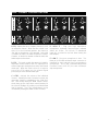
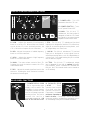
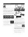
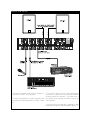
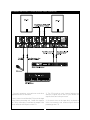
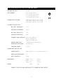
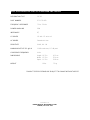
PORTABLE
SOUND SYSTEMS
From Fender Pro Audio
Owner's Manual for
LTB Portable Sound System
P/N 051923
REV B
Fender Musical Instruments
7975 North Hayden Road, Scottsdale, Arizona 85258 U.S.A.
Fender knows the importance of sound reinforcement. From the simple box-top mixer
to today's professional touring concert systems, the need to communicate, to make the
connection between the performer and the audience is foremost in Fender's mind.
Perhaps no other single piece of gear can make or break your band's sound. You see,
your sound system is more than just a combination of dials, wires and speakers. It is
an integral part of the audio chain and should be treated with special care and attention
to detail.
At Fender, we know what building quality musical instruments and sound reinforcement
equipment is all about. In fact, many of the world's best sounding electric musical
instruments and sound reinforcement equipment proudly wear the Fender name.
Whether you need a simple box top powered mixer for your Saturday afternoon jam, or
a professional full-size concert system, Fender has the sound reinforcement equipment
to meet your needs. Likewise, your decision to purchase Fender pro audio gear is one
you will appreciate with each performance for years to come.
Wishing you years of enjoyment and a heartfelt thank you,
Bill Schultz
Bill Schultz
Chairman
Fender Musical Instruments Corporation
THE FENDER LTB
POR TABLE POWERED
MIXER
INTRODUCTION
The LTB: an 80 watt professional powered mixer
from your friends at Fender® Pro Audio. We are sure
you will find your new LTB sound system to be both
a unique and effective sound reinforcement product,
providing years of trouble-free service. With ease of
setup in mind, the integrated mixer/amplifier design
combined with the full-range LTB-10 speaker
enclosures makes your LTB a versatile, yet simple to
operate sound system. Included in your LTB
package is one dynamic cardiod microphone, one
microphone cable and two speaker cables;
everything you need to get started.
80 Watts into 4Ω
3-Band Equalizer
+15V DC Phantom Power
Individual Channel Effects Level Control
Both 1/4 inch Phone TS and 3-Pin XLR
Female Input Connectors
Enclosed in a boxtop style cabinet, your LTB
mixer/amplifier features individual channel preamps,
+15V DC phantom power, line and mic level channel
inputs, a patch bay and much, much more. With
1/4 inch TS phone jacks and 3-Pin XLR female
input jacks, your LTB sound system can
accommodate a wide variety of input connections
and signal levels.
Patch Points for Line Level Outboard Gear
Full-bodied Spring Reverb
Everything You Need to Get Started:
LTB Mixer / Amplifier
One Dynamic Cardiod Microphone
One Microphone Cable
Two Speaker Cables
Two Full-Range Speaker Enclosures
Ideal for live music, churches, auditoriums, hotel
conference or meeting rooms, your LTB sound
system is suitable for a variety of sound
reinforcement applications. The LTB mixer /
amplifier‘s front panel patch bay makes using
outboard effects gear and signal processing
equipment a snap. Moreover, the patch bay
provides easy access for adding or rerouting power
amplifiers. Still, the LTB-10 speaker enclosures
deliver a powerful, full-range sound ideal for music,
vocals or whatever your sound needs require.
Designed for the both novice, as well as the
seasoned audio professional, your LTB sound
system will provide years of reliable, trouble-free
service, day in and day out. Please read through
this owner’s manual in order to more thoroughly
understand the operation of your LTB portable
sound system.
WARNING:
- TO REDUCE THE RISK OF FIRE OR SHOCK
HAZARD, DO NOT EXPOSE THIS UNIT TO RAIN OR
MOISTURE.
- NO USER SERVICEABLE PARTS INSIDE, REFER
SERVICING TO QUALIFIED PERSONNEL ONLY.
- THIS UNIT MUST BE EARTH GROUNDED.
3
INPUT CHANNEL CONTROL FUNCTIONS
A
B
C
D
E
A. EQ - Adjusts the tone / frequency boost or cut of
its respective channel. When the tone control is set
at the 12 o’clock (notched) position, the channel is
“flat” with no frequencies cut or boosted. As the dial
is rotated clockwise, the treble response increases.
Likewise, as the dial is rotated counterclockwise the
treble response decreases.
D. HIGH Z - Plug your high impedance
microphones, keyboards, drum machines, outboard
effects, etc. in here. This 1/4 inch, TS unbalanced
input jack is suited for use with items having line
level outputs.
E. LOW Z - Plug your microphone in here. This
three pin XLR balanced female input connector is
intended for input signals from low impedance
microphones. Pins 2 and 3 automatically provide
Phantom Power (+15V DC) for some condenser
style microphones.
B. EFX - This knob controls the amount of signal its
respective channel sends to the EFX output jack for
external signal processing devices and to the internal
reverb pan. When the knob is set at 0, no signal is
sent to the EFX output jack for external signal
processing or to the internal reverb pan.
C. LEVEL - Adjusts the volume of the individual
channel. Rotating the knob clockwise increases the
respective channel’s contribution to the “Main Out”
mix. After slowly raising the MAIN volume control,
slowly bring up this input level control listening for
the onset of feedback or howling or until the desired
level is reached. The LTB’s overall volume can be
increased by rotating the MAIN control clockwise.
4
MASTER CONTROL PANEL FUNCTIONS
B
A
F
C
G
D
E
F. POWER LED - This LED
illuminates when the LTB is on.
G. POWER SWITCH - Turns
the AC power ON and OFF.
H
I
J
H. MAIN - This 1/4 inch, TS,
unbalanced, line level output is
designed to feed the LTB’s main
bus signal to an external power
amplifier or main house mixer.
K
A. LOW - Adjusts the amount of low frequency
boost or cut in the LTB. When all the tone controls
are set at their 12 o’clock (notched) position, the
LTB is “flat” with no frequencies cut or boosted.
I. EFX - This 1/4 inch, TS, unbalanced, line level
output jack is designed to feed the LTB’s effects bus
signal to an external signal processing device, such
as a digital delay or a chorus unit.
B. MID - Adjusts the amount of middle frequency
boost or cut in the overall mix.
J. AUX IN - This 1/4 inch, unbalanced, TS, line level
input jack is designed to accept signal from an
external processing device, such as a digital delay or
a chorus unit. Any signal entering this jack is mixed
into the Main bus signal.
C. HIGH - Adjusts the amount of high frequency
boost or cut in the overall mix.
D. MAIN - The main volume control of the LTB.
Rotating the knob clockwise increases the LTB’s
overall volume level.
K. FTSW - This 1/4 inch, TS, unbalanced, output
jack is designed for use with an optional footswitch
(P/N 048458). When a footswitch is inserted into
this jack, the LTB’s internal reverb can be turned on
or off remotely.
E. REV - Adjusts the reverb signal level sent to the
main mix. Rotating the knob clockwise increases
the amount of reverb signal.
REAR PANEL FUNCTIONS
L
L. POWER SUPPLY CORD
- This is a grounding type
supply cord to reduce the
possibility of shock hazard.
Completely unwind the cord
from its cord wrap to prevent
blocking air flow. Be sure to
connect the cord to a
grounded receptacle. DO
NOT ALTER THE AC PLUG.
M. PARALLEL SPKR M
JACKS
These
speaker level output
jacks feed your main
speaker enclosures.
80W
Remember, the total
4Ω MIN. LOAD TOTAL
minimum impedance
load is 4 ohms. Connecting a load of less than 4
ohms may result in unsatisfactory performance such
as overheating to the point of thermal shutdown.
5
BASIC SETUP OF YOUR LTB
Before using the LTB, please read and
follow the steps listed below:
1. IMPORTANT Heed all safety warnings when
operating the LTB.
2. Please be sure to check for these items. The
LTB sound system comes complete with 2 LTB-10
Speaker cabinets, 2 speaker cables, 1 microphone
cable and 1 dynamic cardioid microphone.
3. Make sure the power switch is in the OFF
position, the EQ, LOW, MID and HIGH tone controls
are in their 12 o’clock notched positions and all
channel LEVELS, the MAIN and the REV are in their
MIN positions.
Stereo Cassette
RECORD LEVEL L
R
LEFT
9
2
0
O 1 3
1 2 4
P L AY
POWER
RIGHT
RECORD
1
2
PA U S E
STOP
REW
FF
1
1
2
2
0
TA P E S E L E C T
1
2
3
3
-5
NORMAL
Cr O 2
4
4
Volume
0
M E TA L
-5
Value
1
2
3
4
5
6
7
8
Value
Value
Value
Value
Value
Value
Value
Value
Yes
This Illustration was done
A
B
Value
Value
by Phil Sanchez
January 27, 1997
No
This full page illustration can be found on page 8.
4. Next, plug the supply cord into a power source
with the correct voltage.
7. Turn all instruments, outboard gear and other
equipment ON before powering up the LTB.
5. Connect the speaker cables
from the LTB’s SPEAKER
OUTPUT jacks located on the rear
of the LTB mixer to the input jacks
on the speaker cabinets.
8. Slowly raise the MAIN volume control to its 12
o’clock position. Next, slowly bring up the
appropriate channel input level control (ie: if the
microphone is plugged into the channel 1 inputs, the
appropriate channel control is labeled 1), listening for
the onset of feedback or howling or until the desired
level is reached. The LTB’s overall volume can be
increased by rotating the MAIN
control clockwise.
80W
4Ω MIN. LOAD TOTAL
6. Connect the cord(s) from any microphones,
instruments, outboard gear or other signal source(s)
to the appropriate input jack(s) on your LTB.
9. If using external signal processing
devices, slowly raise the appropriate channel EFX
control until the desired level is reached (ie: if the
microphone is plugged into the channel 1 inputs, the
appropriate channel control is labeled 1).
10. When shutting down the LTB, turn OFF the LTB
FIRST then any additional outboard gear,
instruments or other equipment.
For more detail on setting up your LTB, please refer
to the diagrams on pages 9 and 10.
6
GROUNDING AND HUMS
TROUBLESHOOTING
Ground loops are one of the most
common causes of hum and buzz in
sound reinforcement systems and other
audio products. A ground loop usually
occurs if the separate pieces of
equipment are plugged into different AC
circuits. Also, if the audio wiring is placed too close
to the power cords, hums or buzzes can bleed into
the system. Still, improperly maintained power and
audio cables are yet another cause of bothersome
noise. In order to help minimize stray hums and
buzzes, here are some helpful hints.
If the LTB is set up but does not
function, please check the following
items:
• Is the LTB 's power cord properly plugged into an
electrical outlet?
• Is there power at the outlet?
• Are the volume control knobs on the LTB turned
above the MIN position?
• Are the volume control knobs on your instruments
turned above their minimum position?
• Is the mic/instrument properly plugged into the
LTB ?
• Is the mic/instrument turned on?
• Are your audio cables frayed, cut or damaged?
• If using an outboard gear, are the cords
properly connected?
• Are the speaker cables properly connected?
• Is there power to the outboard gear?
• Are the levels on your outboard gear above their
minimum positions?
• (If applicable) does your instrument have power?
1. Keep all electronics connected to the sound
system on the same electrical circuit.
2. Keep audio signal cables away from the AC
power cords.
3. Use balanced cables when applicable.
4. Always plug the LTB into a grounded AC electrical
outlet.
5. Be sure to use properly maintained cords and
cables with the LTB.
VINYL COVERING CARE
If after checking all of the above the LTB is still not
performing correctly, consult your nearest authorized
Fender Service Center.
The LTB mixer and speaker cabinets
are covered in vinyl for long life and
lasting good looks. To clean the
cabinets, use a sponge dampened with
a light soapy solution. Avoid spilling any
liquids on the operating surface, grilles, volume and
tone controls, switches and line cord inputs.
ALWAYS unplug the LTB before cleaning it or
approaching it with fluids. Before plugging in the
LTB wait until the unit has completely dried.
7
SIMPLE LTB SETUP
Stereo Cassette
RECORD LEVEL L
R
LEFT
9
2
0
O 1 3
1 2 4
P L AY
POWER
RIGHT
RECORD
1
2
PA U S E
STOP
REW
FF
1
1
2
2
-5
0
TA P E S E L E C T
1
2
NORMAL
Cr O 2
4
4
Volume
0
3
3
M E TA L
-5
Value
1
2
3
4
5
6
7
8
Value
Value
Value
Value
Value
Value
Value
Value
Yes
This Illustration was done
A
B
Value
Value
by Phil Sanchez
January 27, 1997
No
1. Connect the speaker cords from the PARALLEL
SPKR JACKS to the LTB-10 speakers.
3. The LEVEL control in each channel strip adjusts
the amount of signal sent to the main bus where all
channel signals are summed. The MAIN knob in
the master section adjusts the volume level to the
main speakers.
2. Connect a microphone to a LOW Z input jack and
any keyboard or other instrument to a HIGH Z input
jack.
4. Be sure to turn the tape deck, keyboard or other
instruments and gear on before powering up the LTB.
8
RUNNING AN EFFECTS PROCESSOR THRU YOUR LTB
Volume
Value
1
2
3
4
5
6
7
8
Value
Value
Value
Value
Value
Value
Value
Value
Yes
This Illustration was done
A
B
Value
Value
by Phil Sanchez
January 27, 1997
No
1. Connect speakers, microphones and other
equipment to the LTB as before.
3. The EFX knob on each channel adjusts the
amount of signal sent to the EFX jack where the
signal is then sent to the processor.
2. Next, connect a cord from the EFX jack to the input
on the effects processing unit. Return the signal to
the LTB by connecting a cord from the output of the
effects unit to the AUX IN jack on the LTB.
4. Be sure to turn on the tape deck, keyboard or
other instruments and outboard gear before
powering up the LTB.
9
SPECIFICATIONS FOR THE LTB POWERED MIXER
DESIGNATION TYPE
PR 345
PART NUMBER
071-1700-000
071-1730-000
071-1740-000
071-1760-000
POWER SPECIFICATIONS
120V version: 120V AC, 60 Hz, 270W
230V version: 230V AC, 50 Hz, 270W
240V version: 240V AC, 50 Hz, 270W
(120 V)
(240 V) Aust
(230 V) UK
(230 V) Euro
PRE-AMPLIFIER SECTION
MIC INPUT IMPEDANCE
2.7 kΩ
LINE INPUT IMPEDANCE
100 kΩ
MIC INPUT SENSITIVITY
2 mV
LINE INPUT SENSITIVITY
6 mV
CHANNEL TONE CONTROLS Low +/- 15 dB @ 30 Hz
Mid +/- 15 dB @ 1 kHz
High +/- 15 dB @ 15 kHz
OVERALL AMPLIFIER
FREQUENCY RESPONSE
-3 dB @ 10 Hz to -3 dB @ 50 kHz
PHANTOM POWER
+15 V DC
(Aux In @ 10 mV)
POWER AMPLIFIER SECTION
POWER OUTPUT
80W @ <0.03% T.H.D. + noise @ 1 kHz into 4 Ω
RATED LOAD IMPEDANCE
4Ω
INPUT SENSITIVITY
34 mV
DIMENSIONS
WEIGHT
Height: 5.75 in
Width: 17.5 in
Depth: 10 in
20 lbs
14.6 cm
43 cm
25.5 cm
9 kg
PRODUCT SPECIFICATIONS ARE SUBJECT TO CHANGE WITHOUT NOTICE.
10
SPECIFICATIONS FOR THE LTB-10 SPEAKER ENCLOSURE
DESIGNATION TYPE
PR 355
PART NUMBER
071-1710-000
FREQUENCY RESPONSE
75 Hz - 20 kHz
POWER HANDLING
60W
IMPEDANCE
8Ω
LF DRIVER
10” with 1.5” voice coil
HF DRIVER
Piezoelectric Horn
SENSITIVITY
94 dB, 1W - 1M
MAXIMUM OUTPUT SPL @ 1 M
111dB continuous, 117 dB peak
CROSSOVER FREQUENCY
4 kHz
DIMENSIONS
Height: 16.75 in
Width: 12.75 in
Depth: 11.75 in
WEIGHT
16 lbs
42.5 cm
32.4 cm
29.8 cm
7.3 kg
PRODUCT SPECIFICATIONS ARE SUBJECT TO CHANGE WITHOUT NOTICE.
A PRODUCT OF:
FENDER MUSICAL INSTRUMENTS CORP.
CORONA, CA 91720 USA