1
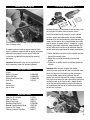
.36NT Control Line
Evolution Engine
®
US E R GUIDE
Introduction
Congratulations on your purchase of the newest
and one of the most technically advanced 2-stroke
model airplane engines in the world. Whether
you are new to the sport of model aviation or an
experienced flier, you will enjoy the features of the
new Evolution® Engines Control Line (CL) Engine.
The Evolution CL Engine is designed to be the most
powerful yet controllable in its class, extremely
easy to start and operate, and provide years of
enjoyable service. It incorporates many unique
design features, such as our Set Right™ needle
valve assembly. Every feature is designed to ensure
success with your new engine.
This user’s guide is intended to provide the basic
information to operate and maintain your Evolution
CL Engine.
Important: While the Evolution engine is extremely
easy to operate, if this is your first experience flying
a model airplane, it is highly recommended that
you have the help of an experienced modeler during
the first few flights. Your local hobby store or flying
club can put you in touch with an experienced pilot
in your area.
Glow Plug
Venturi
High-Speed Needle
Glow Plug
Venturi
2
Mounting the Engine
Installing the Muffler
The muffler mounting accessory package includes mounting screws
(2), lock washers (2), muffler gaskets (2) and an L- wrench.
Securely tighten all engine mounting screws and re-check tightness
before each flying session.
All model airplanes include an engine mount of some
type. It is extremely important that the engine be securely
mounted to the airplane’s engine mount. Follow the
instructions included with the airplane for mounting
the engine.
Important: Before each flying session, check that all
engine mounting screws are securely tightened.
Included Items
Engine
Muffler (standard) Muffler (Tongue) Muffler Screw Gasket Set
Glow Plug
Wrench
Instructions
Decal Sheet
EVO036601
EVO036601L
EVO036E36A,
EVOGP1
Using the included muffler mounting screws and lock
washers, attach your choice muffler with the included
hex wrench. Be sure the lock washers are placed over the
screws and that one gasket is placed between the muffler
and the engine. A second gasket is included as a spare.
Securely tighten both screws with moderate torque. The
exhaust outlet of the muffler can be rotated to allow the
exhaust outlet to be repositioned for various applications.
1.Loosen the lock nut on the back of the muffler and then
loosen the assembly screw.
2.Rotate the rear half of the muffler to the desired
position.
3.Tighten the assembly screw first and then tighten the
lock nut.
Important: After five runs, retighten the muffler
mounting screws and head bolt. Heat and vibration from
these first few runs can cause the gasket to compress.
Once the muffler screws are re-tightened, they will
remain tight and leak-free until the muffler is removed.
Also, if you have chosen the tube style muffler, tighten the
muffler thru-bolt at this time as well—loosen the lock
nut on the back of the muffler, tighten the thru-bolt via
the screwhead at the front of the muffler then retighten
the lock nut at the rear.
Optional Items
Glow Plug (2 & 4 Cycle)
Glow Plug Wrench
Manual Fuel Pump
Blue Block After Run Oil
Metered Glow Driver with Nicad
Power Pro 12V Starter
Fieldmate Prebuilt Flight Box
EVOGP1
HAN2510
HAN118
EVOX1000
HAN7101
HAN161
HAN117
3
Attaching the Propeller and Spinner
Attaching the Fuel Lines
Using medium silicone fuel tubing, attach the fuel tank’s
clunk line to the fuel nipple. This line will supply fuel to
the engine. Attach the vent line to the muffler pressure
nipple. This line pressurizes the fuel tank with the muffler
pressure, creating consistent fuel flow, regardless of the
airplane’s attitude.
Fuel Line
Vent Line
Securely tighten the prop nut using an adjustable wrench.
Starting the Evolution Engine
Fuel
The Evolution engine comes baseline adjusted from the
factory. We recommend using high quality Cool Power
Omega or Power Master fuels containing 5 to 10% Nitro.
The Evolution engine has been test run using these fuels.
If another brand of fuel is used, it may be necessary to
slightly adjust the needle valves to compensate for the
differences in fuel.
Glow Plug
If you are using an aftermarket spinner nut, install the
propeller, the prop washer and then the prop nut in that
order (see photo). Securely tighten the prop nut using
whatever is most suitable to tighten the spinner nut (if
you are using one). In the photo above we are using a
spinner nut only.
The Evolution engine comes with a specially designed
“Super Plug”. The plug’s unique shape directs incoming
fuel/air mixture away from the plug element. When
replacing the plug, be sure to replace it with another
Evolution 2-4 stroke Super Plug (EVOGP1).
Starting the Engine
Step 1.Fill the tank with the above-mentioned 5 or
10% fuel.
Step 2.Reattach the fuel lines, making sure the vent
and clunk line are attached to the fuel nipple
and the muffler pressure nipple.
Caution: Do not attach the glow driver yet.
Step 3.Place your thumb over the venturi and flip the
4
prop counter-clockwise through 6 -10 complete
revolutions, thus priming the engine. Have a
helper hold your airplane.
Step 4. Attach the glow driver.
Step 5.Turn the engine over using an electric starter.
The engine should fire within seconds of applying
the starter.
Step 6.Remove the glow driver.
Step 7. Allow the engine to run for 30 seconds. And then
adjust the needle valve for your desired ground rpm. We
suggest you set the needle valve so the engine is running
at a fast 4-cycle if you are using the engine for stunt and
sport applications.
SetRight Needle Valves
The design of the SetRight needle valve system is such
that, during normal operating conditions, the typical user
will find that the normal range of adjustment allowed by
the system is more than adequate for most situations.
As a matter of fact, we intended this to be used as a
tool to identify operating problems. If you find that the
range of adjustment allowed by the SetRight needle is
inadequate after your initial period of running, then a
problem in your engine system has occurred. This might
be a bad glow plug, dirty or old fuel, an air leak in the
fuel system somewhere or any number of other reasons.
Do not make any permanent adjustment range changes
to the SetRight needle system if it was once working
correctly for you and now does not. Investigate other
problems first.
However, occasionally due to atmospheric, altitudinal
or fuel conditions, you may find that the range of
adjustment built into the SetRight needle valve system
is inadequate for your needs. These conditions are rare
and easy to fix.
Needle Limiters
In most conditions: With changes in flying field
altitudes, changes in temperatures, etc., it will be
necessary to adjust the needle valve. The needle
has a limiter to restrict the movement to just under
one full needle turn, more than enough range for
most conditions.
If your engine starts from the above procedure, but won’t
reliably continue to run with the glow driver removed,
follow the steps above right.
SetRight Needle Valve Correction
Should the SetRight needle valve need to be
adjusted outside of the factory-established
parameters, simply pull out the detent spring on
the high-speed needle assembly and move the
needle valve in the desired direction so the SetRight
pin passes the spring detent. You now have
re-established a new range for your purposes.
Note: We have found that if you rotate the blue
collar that locks down the needle clip so that the
setscrew is located adjacent to the actual clip
itself, this will easily increase the tension on the
needle clip and hold the needle in place more
securely.
Note: We have found that the best rpm to start with for
this engine is to set the needle so the ground rpm is
9200 - 9500. This will provide a solid 4-stroking style
run with a 2-4 break when needed. Pick the appropriate
prop to match the application and airplane. A 4-5 pitch
prop at these rpms will yield a 5.2-5.4 second lap time
on 60- to 62-foot lines. We recommend as a starting
point the mid-sized venturi .236 in (6mm) and an 11 x 4
to 11 x 5 two-blade propeller.
5
Why would fuel go “bad”?
The largest portion of the fuel is methanol (alcohol).
Methanol is hygroscopic; it attracts moisture. This can
cause your fuel to be contaminated with water, which will
cause poor engine performance. Additionally, the UV rays
in sunlight will eventually break down the nitromethane if
the fuel jug is stored in sunlight for long periods of time.
How can you tell when your fuel has gone “bad”?
The first indications will generally be the inability to start
the engines at previously run needle-valve settings.
Another clue might be that the engine has very poor idle,
runs but bogs down tremendously during run up and/or
will not attain the same rpms that you are used to.
How do I keep my fuel fresh?
If you have the opportunity, look for someone at a flying
field on a sunny day who has a jug of fuel that is only
1/4 full. What you may notice is that there are droplets
attached to the top and sides of the container. This is
the moisture in the air that is condensing inside the jug
because of the greenhouse effect of the semi-translucent
plastic jug. The only way to overcome the greenhouse
effect is to store your fuel in a metal can.
You can also combat the effects of the moisture in the air
by squeezing all the extra air from your fuel container at
the end of the day or transferring your fuel into smaller
containers as the level of the fuel is reduced in your
gallon jug. Many pilots will invest in 1/2 gallon or quartsize containers and only bring that amount of fuel to the
field on any given day. This allows their main supply of
fuel to stay at home in a controlled storage environment,
virtually ensuring problem-free fuel.
6
How to tell if your glow plug is bad
The glow plugs on the market today are designed
to provide good service to the user and may last a long
time or a short time, all dependent upon the way you
choose to operate your engine.
Physical indications that you might need to change the
glow plug are:
1. Twisted or mangled glow plug element (usually
caused by too high a compression ratio).
2. Small “bumps” are attached to the glow plug
element. This will generally be most noticeable
during the break-in process. These are actually
tiny pieces of aluminum that have attached to the
element and will severely hinder the operation of
the glow plug.
3. The glow plug element is no longer shiny but is dull,
almost a white powder color. (This just comes with
age and is a by-product of the catalytic reaction.
The shinier the wire, the better the catalytic reaction
can be.)
Operating indications that you need to change your
glow plug are:
1. The glow element will not light with a charged glow
igniter. This indicates that there is a physical short
or breakage in the element wire itself.
2. Glow plug lights but the engine will not continue
running once the battery is disconnected. (This is
usually an indication of the microscopic particles
we discussed earlier.)
3. Glow plug lights, engine runs but there is a
perceptible loss of rpm at full throttle when the
battery is disconnected. This is a typical indication
that the white powder residue is building to the
point that the catalytic reaction of the glow plug is
no longer anywhere close to being optimum.
Evolution Control Line Engine Specifications
Items
EVOE0365
Disp Bore Stroke Weight
(c.i.) (mm) (mm)
(oz)
.354" .806" .695"
9.2
Crank K
(ISO)
1/4X28
Cylinder Propeller
ABC
11x4 or 11x5
F
H
G
B A
C
Dimensions(mm)
EVOE0365
A
30
D
B
38
Troubleshooting Guide
Engine Won’t Fire
• Glow starter not charged
- Charge glow starter
• Glow plug burnt out
- Replace glow plug
• No fuel is getting to the carburetor
- Check tank, fuel lines reversed
• The starter is reversed
- Reverse the polarity on the starter cables
Engine Quits Repeatedly
• Needles need adjusting
- See adjustment procedure
• Bad or old fuel
- Replace with fresh fuel
• Worn out glow plug
- Replace with new EVOGP1 super plug
Engine Runs Inconsistently
• Hole in fuel line
- Replace fuel line
• Bad or old fuel
- Replace with fresh fuel
Maintenance
After each flying session:
E = height
F = length
G = crankshaft thread size
H = muffler bolt spacing
1. Fully drain the fuel from the tank.
2. Start the engine and run it until the fuel is
completely run out of the engine.
3. Try starting the engine three more times or until
C
15
D
47
E
78
F
72
G
1/4X28
H
37
it will no longer fire. This gets all the fuel out of
the engine.
At the end of every flying session, several drops (about
10) of after-run oil (Evolution Engine's Blue Block Rust
Inhibitor) should be applied into the venturi and the
engine should be flipped over for a few seconds with the
starter. This will prevent rust and corrosion.
If you need additional help or have any questions, please call Horizon’s Service Center.
Horizon has trained technicians who are qualified to answer your engine questions.
Evolution/Horizon Service Center
4105 Fieldstone Road
Champaign, IL 61822
877-504-0233
European Union:
Electronics and engines requiring inspection or repair should be shipped to one of the
following addresses:
Horizon Hobby UK
Units 1-4 Ployters Rd
Staple Tye, Southern Way
Harlow
Essex CM18 7NS, United Kingdom
Please call +44 1279 641 097 or [email protected] with any questions or
concerns regarding this product or warranty.
Horizon Technischer Service
Otto Hahn Str. 9a
25337 Elmshorn
Germany
Please call +49 4121 46199 66 or [email protected] with any questions or
concerns regarding this product or warranty.
7
WARRANTY INFORMATION
Warranty Period
Exclusive Warranty- Horizon Hobby, Inc., (Horizon)
warranties that the Products purchased (the
“Product”) will be free from defects in materials and
workmanship for a period of 2 years from the date of
purchase by the Purchaser.
Limited Warranty
(a) This warranty is limited to the original Purchaser
(“Purchaser”) and is not transferable. REPAIR OR
REPLACEMENT AS PROVIDED UNDER THIS WARRANTY
IS THE EXCLUSIVE REMEDY OF THE PURCHASER. This
warranty covers only those Products purchased from
an authorized Horizon dealer. Third party transactions
are not covered by this warranty. Proof of purchase is
required for warranty claims. Further, Horizon reserves
the right to change or modify this warranty without
notice and disclaims all other warranties, express or
implied.
(b) Limitations- HORIZON MAKES NO WARRANTY OR
REPRESENTATION, EXPRESS OR IMPLIED, ABOUT
NON-INFRINGEMENT, MERCHANTABILITY OR FITNESS
FOR A PARTICULAR PURPOSE OF THE PRODUCT. THE
PURCHASER ACKNOWLEDGES THAT THEY ALONE HAVE
DETERMINED THAT THE PRODUCT WILL SUITABLY
MEET THE REQUIREMENTS OF THE PURCHASER’S
INTENDED USE.
(c) Purchaser Remedy- Horizon’s sole obligation
hereunder shall be that Horizon will, at its option,
(i) repair or (ii) replace, any Product determined
by Horizon to be defective. In the event of a defect,
these are the Purchaser’s exclusive remedies. Horizon
reserves the right to inspect any and all equipment
involved in a warranty claim. Repair or replacement
decisions are at the sole discretion of Horizon.
This warranty does not cover cosmetic damage or
damage due to acts of God, accident, misuse, abuse,
negligence, commercial use, or modification of or to
any part of the Product. This warranty does not cover
damage due to improper installation, operation,
maintenance, or attempted repair by anyone other
than Horizon. Return of any goods by Purchaser must
be approved in writing by Horizon before shipment.
8
Damage Limits
HORIZON SHALL NOT BE LIABLE FOR SPECIAL,
INDIRECT OR CONSEQUENTIAL DAMAGES, LOSS OF
PROFITS OR PRODUCTION OR COMMERCIAL LOSS IN
ANY WAY CONNECTED WITH THE PRODUCT, WHETHER
SUCH CLAIM IS BASED IN CONTRACT, WARRANTY,
NEGLIGENCE, OR STRICT LIABILITY. Further, in
no event shall the liability of Horizon exceed the
individual price of the Product on which liability is
asserted. As Horizon has no control over use, setup,
final assembly, modification or misuse, no liability
shall be assumed nor accepted for any resulting
damage or injury. By the act of use, setup or assembly,
the user accepts all resulting liability.
If you as the Purchaser or user are not prepared
to accept the liability associated with the use of
this Product, you are advised to return this Product
immediately in new and unused condition to the place
of purchase.
LAW: These Terms are governed by Illinois law (without
regard to conflict of law principals).
Safety Precautions
This is a sophisticated hobby Product and not a toy.
It must be operated with caution and common sense
and requires some basic mechanical ability. Failure to
operate this Product in a safe and responsible manner
could result in injury or damage to the Product or
other property. This Product is not intended for use by
children without direct adult supervision. The Product
manual contains instructions for safety, operation
and maintenance. It is essential to read and follow all
the instructions and warnings in the manual, prior to
assembly, setup or use, in order to operate correctly
and avoid damage or injury.
Questions, Assistance, and Repairs
Your local hobby store and/or place of purchase
cannot provide warranty support or repair. Once
assembly, setup or use of the Product has been
started, you must contact Horizon directly. This
will enable Horizon to better answer your questions
and service you in the event that you may need any
assistance. For questions or assistance, please direct
your email to [email protected], or
call 877.504.0233 toll free to speak to our product
support staff.
Inspection or Repairs
If this Product needs to be inspected or repaired,
please call for a Return Merchandise Authorization
(RMA). Pack the Product securely using a shipping
carton. Please note that original boxes may be
included, but are not designed to withstand the rigors
of shipping without additional protection. Ship via a
carrier that provides tracking and insurance for lost
or damaged parcels, as Horizon is not responsible for
merchandise until it arrives and is accepted at our
facility. A Service Repair Request is available at www.
horizonhobby.com on the “Support” tab. If you do not
have internet access, please include a letter with
your complete name, street address, email address
and phone number where you can be reached during
business days, your RMA number, a list of the included
items, method of payment for any non-warranty
expenses and a brief summary of the problem. Your
original sales receipt must also be included for
warranty consideration. Be sure your name, address,
and RMA number are clearly written on the outside of
the shipping carton.
Warranty Inspection and Repairs
TO RECEIVE WARRANTY SERVICE, YOU MUST INCLUDE
YOUR ORIGINAL SALES RECEIPT verifying the proofof-purchase date. Provided warranty conditions have
been met, your Product will be repaired or replaced
free of charge. Repair or replacement decisions are at
the sole discretion of Horizon Hobby.
Non-Warranty Repairs
SHOULD YOUR REPAIR NOT BE COVERED BY
WARRANTY, THE REPAIR WILL BE COMPLETED AND
PAYMENT WILL BE REQUIRED WITHOUT NOTIFICATION
OR ESTIMATE OF THE EXPENSE UNLESS THE EXPENSE
EXCEEDS 50% OF THE RETAIL PURCHASE COST. By
submitting the item for repair you are agreeing to
payment of the repair without notification. Repair
estimates are available upon request. You must
include this request with your repair. Non-warranty
repair estimates will be billed a minimum of ½ hour
of labor. In addition you will be billed for return freight.
Please advise us of your preferred method of payment.
Horizon accepts money orders and cashiers checks,
as well as Visa, MasterCard, American Express, and
Discover cards. If you choose to pay by credit card,
please include your credit card number and expiration
date. Any repair left unpaid or unclaimed after 90 days
will be considered abandoned and will be disposed of
accordingly. PLEASE NOTE: NON-WARRANTY REPAIR
IS ONLY AVAILABLE ON ELECTRONICS AND MODEL
ENGINES.
Electronics and engines requiring inspection or repair
should be shipped to the following address:
Horizon Service Center
4105 Fieldstone Road
Champaign, Illinois 61822
All other Products requiring warranty inspection or
repair should be shipped to the following address:
Horizon Product Support
4105 Fieldstone Road
Champaign, Illinois 61822
PLEASE CALL 877-504-0233 WITH ANY QUESTIONS
OR CONCERNS REGARDING THIS PRODUCT OR
WARRANTY.
European Union:
Electronics and engines requiring inspection or repair
should be shipped to the following address:
Horizon Hobby UK
Units 1-4 Ployters Rd
Staple Tye
Southern Way
Harlow
Essex CM18 7NS
United Kingdom
Please call +44 (0) 1279 641 097 or email
[email protected] with any questions or
concerns regarding this product or warranty.
Horizon Technischer Service
Otto Hahn Str. 9a
25337 Elmshorn
Germany
Telephone: +49 4121 46199 66
Fax: +49 4121 46199 70
Mail: [email protected]
9
10
No.
Description No.
Description
1
2
3
4
5
6
7
8
9
10
11
12
13
14
15
16
Crankcase
Rear Cover with Gasket
Piston & Liner Set (ABC)
Connecting Rod (Dual Bushing)
Wrist Pin w/Clips (Teflon)
Crankshaft (1/4 X 28)
Cylinder Head
Cylinder Head Shims
Prop Driver
Spacer Washer
Carburetor Retainer (Drawbar)
Prop Washer
Prop Nut (1/4 X 28)
Gasket Set, Engine
Ball Bearing, Front (Rubber Seal)
Ball Bearing, Rear (Open Race)
17
18
19
20
21
22
23
24
25
26
27
28
29
30
31
32
Screw Set, Engine
Muffler (Standard)
Muffler (Tongue Style .36)
Muffler Gasket & Mounting Screw Set
Spraybar Bracket (Remote)
Spraybar (Remote)
High-Speed Needle Valve Ratchet
Fuel Nipple & Gasket Set
Venturi Set (3 pcs.)
Venturi Fuel Nipple
Propeller Washer & Nut Set
Needle Valve Assembly
High Speed Needle Valve
Collar w/Set Screw
Carburetor Gasket O-Ring Set
Small Parts Set, Carburetor
Cross-Reference of Evolution .36 CL Part Number
#
1
2
3
4
5
6
7
8
9
10
11
12
13
14
15
16
17
18
19
20
21
22
23
24
25
26
27
28
29
30
31
32
Description .36CL
CrankcaseEVO036101
Rear Cover w/GasketEVO032102
Piston & Liner (ABC)EVO036203CL
Connecting Rod (Dual Bushing)
EVO032204
Wrist Pin w/Clips (Teflon)EVO032213
Crankshaft (1/4 x 28)EVO032210
Cylinder HeadEVO036103
Cylinder Head ShimsEVO036112
Prop DriverEVO036219
Spacer WasherEVO032225
Carburetor Retainer (Drawbar)EVO036129
Prop WasherEVO100220
Prop Nut (1/4 x 28)EVO100221
Gasket Set, EngineEVO036416
Ball Bearing, Front (Rubber Seal)
EVO032109
Ball Bearing, Rear (Open Race)EVO028110
Screw Set, EngineEVO036901
Muffler (Standard)EVO036601
Muffler (Tongue Style .36)
EVO036601L
Muffler Mounting Screw Set
w/GasketEVO036E36A
Spraybar Bracket (Remote)
EVO036870
Spraybar, RemoteEVO100830
High-Speed Needle Valve Ratchet
EVO100873
Fuel Nipple & Gasket Set
EVO100114
Venturi Set (3 pcs.)
EVO036827
Venturi Fuel Nipple
EVO100115
Propeller Washer & Nut Set
EVO040228
Needle Valve Assembly
EVO036874
High Speed Needle Valve
EVO100829A
Collar w/Set Screw
EVO100834A
Carburetor Gasket O-Ring Set
EVO036E36B
Small Parts Set, Carburetor
EVO061E61C
11
© 2008 Manufactured Exclusively for Horizon Hobby, Inc. 877-504-0233
www.horizonhobby.com
12958