1
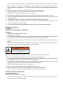
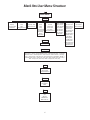
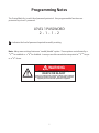
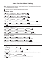
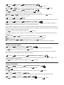
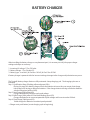
FTA1100
Installation and Operation Instructions
Mark IIXG Diesel Engine Fire Pump Controllers
NS1100-50
ECN 225126
Table of Contents
INTRODUCTION ...........................................................................................................................1
MOUNTING CONTROLLER ............................................................................................................1
Wall Mount................................................................................................................... 1 - 2
Floor/Base Plate Mount......................................................................................................2
MAKING ELECTRICAL CONNECTIONS ...................................................................................... 2 - 4
MAKING SYSTEM PRESSURE CONNECTIONS .................................................................................4
PROGRAMMING THE MARK IIXG ...................................................................................................4
User Interface and Display .................................................................................................5
User Menu Structure..........................................................................................................6
Programming Notes ..........................................................................................................7
MAIN MENU - SETTINGS
System Setup
Display
Brightness ..................................................................................................................8
Contrast .....................................................................................................................8
Invert .........................................................................................................................8
Keyboard ...................................................................................................................8
Language and Units
Language ...................................................................................................................8
Pressure Units ............................................................................................................8
Passwords
Level 1 ........................................................................................................................8
Level 2 ........................................................................................................................8
Date & Time
Time ..........................................................................................................................8
Date ...........................................................................................................................8
Date Format ...............................................................................................................8
Daylight Saving ..........................................................................................................9
Timers
On Delay ....................................................................................................................9
Minimum Run / Off Delay ...........................................................................................9
Pressure
Pressure Units ............................................................................................................9
Start...........................................................................................................................9
Stop ...........................................................................................................................9
Automatic Shutdown Disabled ...................................................................................9
i
Pressure (continued)
Overpressure Alarm .................................................................................................10
Recording - Delta .....................................................................................................10
Sensor ......................................................................................................................10
Calibration ...............................................................................................................10
Engine & Cranking
Control.....................................................................................................................10
Overspeed (Engine Terminal #1) ..............................................................................10
Alarm Limits
Overpressure Alarm Enabled ....................................................................................10
Volts DC ...................................................................................................................10
Volts DC Min. ...........................................................................................................10
Volts DC Max. ...........................................................................................................11
Volts AC Min. ............................................................................................................11
Volts AC Max. ...........................................................................................................11
Coil Check ................................................................................................................11
Feature Settings
AC Power Loss Start ..................................................................................................11
Interlock Alarm ........................................................................................................11
Low Pressure Audible ...............................................................................................11
Low Suction .............................................................................................................11
Main Switch Mis-Set .................................................................................................11
Manual Test ..............................................................................................................12
Pump Run Alarm ......................................................................................................12
Remote Start ............................................................................................................12
User Input ................................................................................................................12
Weekly Test Setup .............................................................................................. 12-13
Low Pump Room Temp ............................................................................................13
Low Reservoir ...........................................................................................................13
Relief Valve Open .....................................................................................................13
High Fuel Level .........................................................................................................13
High Reservoir..........................................................................................................14
Option Settings ...............................................................................................................14
MAIN MENU - EVENT LOG ...........................................................................................................14
MAIN MENU - DATA HISTORY ......................................................................................................14
MAIN MENU - USB
Save to USB .....................................................................................................................14
Remove Drive ..................................................................................................................15
MAIN MENU - FACTORY
Configuration - Model
Serial Number ..........................................................................................................15
Model ......................................................................................................................15
Battery Type .............................................................................................................15
Battery Voltage ........................................................................................................15
ii
MAIN MENU - FACTORY (continued)
Configuration - Model
Pressure Sensor ........................................................................................................15
Autostart NC ............................................................................................................15
User Input Number...................................................................................................15
Low Suction .............................................................................................................15
Screen Saver.............................................................................................................15
Configuration - Options ...................................................................................................15
Configuration - ADC Calibration ......................................................................................15
Diagnostics
Raw Input: Analog ....................................................................................................16
Raw Input: Discrete ..................................................................................................16
Raw Input: Keys ........................................................................................................16
Raw Output: Discrete ...............................................................................................16
Mark IIXG Starts ........................................................................................................16
Lamp Test ................................................................................................................16
Audible Test .............................................................................................................16
USB Test ...................................................................................................................16
Flags ........................................................................................................................16
Tools
Clear Data History ....................................................................................................16
Clear Event Log.........................................................................................................16
Reset to Defaults ......................................................................................................16
Firmware Update .....................................................................................................16
MAIN MENU - ABOUT .................................................................................................................16
BATTERY CHARGER INFORMATION .............................................................................................17
iii
WARNING
RISK OF ELECTRICAL SHOCK
Personal injury could occur.
Ensure all power is disconnected before
installing or servicing this equipment.
These instructions are intended to assist in the understanding of the installation and operation of
the FTA1100. Read through these instructions thoroughly prior to connecting the controller. If there
are any questions unanswered in these instructions, please contact the local Firetrol representative
or factory service department.
INTRODUCTION
Firetrol® FTA1100 combined automatic and manual diesel engine fire pump controllers are intended
for starting and monitoring fire pump diesel engines. They are available for use with 12 or 24 volt
negative ground systems using lead acid or Nickel-Cadmium batteries. FTA1100 fire pump controllers
are listed by Underwriters Laboratories Inc., in accordance with UL218, Standard for Fire Pump Controllers, CSA, Standard for Industrial Control Equipment (cUL), and approved by Factory Mutual. They are
built to meet or exceed the requirements of the approving authorities as well as NEMA and the latest
editions of NFPA 20, Installation of Centrifugal Fire Pumps, and NFPA 70, National Electrical Code.
MOUNTING CONTROLLER—
Note—Consult the appropriate job plans to determine controller mounting location. Controller must
be mounted within view of the engine.
Tools and Materials (all mounting):
1. Assortment of common hand tools of the type used to service electromechanical equipment.
2. Hole (conduit) punch.
3. Drill for drilling wall/floor anchor holes.
4. Hand level.
5. Tape measure.
6. Four (4) anchors with bolts and washer—if wall mount. Six (6) anchors, bolts and washers—if floor/
base mount.
Wall Mount—
Procedure—
1. Locate bottom mounting brackets and hardware.
2. Inspect for damage.
3. Gently lay the controller on its back, using protection so the paint is not damaged. It is best to lay
the controller in a location that is out of the way from actual mounting location.
4. Attach each bracket to the bottom of the enclosure using the supplied hardware . Tighten nuts
securely.
WARNING
RISK OF PERSONAL INJURY
Controller cannot stand upright with the bottom
mounting brackets attached. Leave laying on its
back until the wall anchors are ready for controller
installation.
Note—Refer to the controller dimension drawing for necessary mounting dimensions.
The controller is wall mounted by using four (4) wall anchors, 2 anchors for the top ears and 2
anchors for the bottom mounting brackets. The ears and brackets are dimensionally on the same
center-line for ease in mounting.
1
5. Using either the dimension print or by measuring the distance between the center lines of the 2
lower bracket slots, transcribe this dimension onto the wall. Note: The bottom edge of the enclosure should be a minimum of 12” (305 mm.) from the floor in case flooding of the pump room
occurs.
6. Drill and put 2 anchors into the wall for the 2 lower bracket slot mounts.
7. Mark on the wall, the location of the holes in the upper mounting ears.
8. Drill and put 2 anchors into wall for the upper mounts.
9. Install bolts and washers in 2 lower anchors, leaving a gap between the washer and wall.
10. Lift the controller and place the bottom mounting slots down onto the 2 lower anchor bolts. Do
not tighten bolts.
11. Align holes in upper mounting ears and install 2 bolts and washers in anchors.
12. Shim anchors as necessary to ensure rear of enclosure is vertically level and enclosure is not
stressed. Tighten all 4 anchor bolts.
13. Check to be sure enclosure door opens and closes freely and that enclosure is level.
Floor/Base Plate Mount—
Procedure–
MOUNTING LEGS (OPTIONAL - IF ORDERED)
Procedure—
1. Unpack legs and mounting hardware.
2. Inspect legs for damage.
3. Gently lay the controller on its back, using protection so the paint is not damaged. It is best to lay
the controller in a location that is out of the way from actual mounting location.
4. Attach each leg to the bottom of the enclosure using the provided hardware . Tighten nuts securely.
5. After legs are securely attached, stand the controller up on its legs for mounting. Each leg has 3
holes on the bottom for anchoring to the floor or base plate.
WARNING
RISK OF PERSONAL INJURY
Controller is not free standing! Controller must be
secured to floor or wall surface before opening
door or operating.
Note—Consult the appropriate job plans to determine controller mounting location.
Refer to the controller dimension print for necessary mounting dimensions.
The controller is floor/base plate mounted by using the 3 pre-drilled holes in each leg. The holes
are dimensionally on the same center line for ease in mounting.
6. Using either the dimension print or by measuring distance between the center lines of the holes
on one leg, transcribe these dimensions onto the floor/base plate.
7. Drill 3 holes in floor/base plate for anchoring the leg.
8. Mark location of holes for opposite leg and drill 3 more holes.
9. Secure controller to floor/base plate with bolts and washers and tighten.
10. Check to be sure enclosure door opens freely and that enclosure is level.
MAKING ELECTRICAL CONNECTIONS
Important Precautions—
Prior to making any field connections:
1. Open door of enclosure and inspect internal components and wiring for any signs of frayed or
loose wires or other visible damage.
2
2. Verify that the controller information is what is required on the project:
• Firetrol catalog number
• Engine voltage and polarity of grounding
• Incoming line voltage and frequency
• Maximum system pressure
3. Project electrical contractor must supply all necessary wiring for field connections in accordance
with the National Electrical Code, local electrical code and any other authority having jurisdiction.
4. Refer to the appropriate field connection drawing for wiring information.
Procedure—
All engine connections, remote alarm functions and AC wiring must be brought into the enclosure at the bottom. (See dimension drawing for exact location). A gland plate is supplied for ease of
installation.
Proceed as follows:
1. Use a hole (conduit) punch, not a torch nor a drill, and punch a hole in the gland plate for the size
conduit being used.
2. Install necessary conduit.
Warning—Use only gland plate for conduit entrance. Controller warranty is VOID if any other
location is used.
Note—All field wiring connections are connected to terminal blocks located in the controller.
Terminals for interconnection to the corresponding numbered terminals on the engine terminal
block are located between the circuit breakers (CB1, AC power and CB2-CB3, battery connections).
Not all engines require all terminals to be connected. Reference engine wiring diagram and Field
Connection Diagram for appropriate information. Other terminals are for connecting remote
alarm functions and optional features are located on the controller relay board(s).
AC line connections are made to terminals L1 and L2 (1CB). A ground lug, marked “G” is provided
for grounding. This AC circuit should come from a source having a circuit breaker sized in accordance with the National Electrical Code and other local codes.
3. Pull all wires necessary for engine connections, remote alarm functions, AC power and all other
optional features. Allow enough excess wire inside enclosure to make up connections to the terminal block. Be sure to consult the appropriate field connection diagram. Make sure AC Circuit
Breaker (CB1) and Battery Circuit Breakers (CB2, CB3) are turned “Off”.
Warning—Do not use controller wire way for routing external wiring.
Wire Sizes—
• Use #14 AWG wire minimum for all electrical connections except for battery charger connections. (Battery chargers connected to terminals 6, 8, and 11.)
• On terminals 6, 8, and 11, use the following information to determine wire sizes:
Linear feet (in conduit run)
from controller to terminal
block on engine
0’ to 25’ (0 to 7.62 m.)
25’ to 50’ (7.62 m. to 15.24 m.)
Maximum
Wire Size
#10 AWG (6 mm2)
#8 AWG (10 mm2)
4. Make all field connections to remote alarm functions and any other optional features.
5. Verify AC line voltage and frequency with the controller data plate on the enclosure door prior to
energizing AC power.
3
6. Connect AC power to “L1” and “L2” (CB1) —120 Volt, 60 Hz or as called for on controller data
plate.
7. Connect remote normally open START push-button wires to terminals “13” and “14” (if used).
8. If deluge valve is used, remove jumper from terminals “16” and “17”. Connect wires from normally
closed contact on deluge valve to terminals “16” and “17”.
9. Connect remote normally open shutdown interlock wires to terminals “15” and “16” (if used). A
factory installed jumper will be installed on these terminals. If installing a interlock, this jumper
may be removed, otherwise leave jumper in place until the set up of the Mark IIXG is complete.
10. Check to see that all connections are both correctly wired (in accordance with field connection
diagram) and tight.
11. Close enclosure door.
MAKING SYSTEM PRESSURE CONNECTIONS
The FTA1100 controller requires one (1) “System Pressure” connection from the system piping
to the enclosure. The connection fitting, 1/2” FNPT, is provided on the bottom, external side of the
enclosure for this purpose.
The “Test Drain” connection, located to the left of the “System Pressure” connection, should
be piped to a vented drain or to waste. The “Test Drain” is used only briefly during the weekly test
cycle.
Note—Test drain line must be free flowing. Do not use any valves or plugs on this line.
Refer to NFPA 20 for correct field piping procedure of sensing line between the pumping system
and the controller.
PROGRAMMING THE MARK IIXG
1. Energize (Turn “ON”) circuit breakers 1CB (AC Power), 2CB & 3CB (Battery Connections). Follow
the programming instructions included in this manual to set pressure, timers, etc...
2. When all programming is complete and the unit is ready to put into service, remove interlock
jumper wire from terminals 15 & 16. This jumper is factory installed to prevent starting of the
engine during installation and setup.
4
Mark IIXG User Interface and Display
1
SYSTEM STATUS
132 psi
Ready
1
2
0.8A
0.7A
11.7
11.5
AC POWER AVAILABLE
120~
118~
ALARM
MAIN SWITCH IN AUTO
09-28-2009
14:37:06
MAIN SWITCH IN MANUAL
SYSTEM PRESSURE LOW
DIESEL
ENGINE RUNNING
ENGINE FAIL TO START
2
3
ENGINE TEMPERATURE HIGH
ENGINE OIL PRESSURE LOW
ENGINE OVERSPEED
ENGINE ALTERNATE ECM
Esc
ENGINE FUEL INJECTOR MALFUNCTION
Enter
FUEL LEVEL LOW
4
AUTOMATIC SHUTDOWN DISABLED
5
CHARGER MALFUNCTION
Silence
BATTERY #1 TROUBLE
BATTERY #2 TROUBLE
6
1
2
3
Informational Display
Control Status and System Pressure
Battery 1 & 2 Status - DC Volts, Charging
Amps, AC Volts (charger)
Active Alarms - Primary Status Notification
Date-Time or Active Timer
Secondary Status Notification
ESC Button
Used to go backwards through
menu screens
Enter Button
Used to go forwards through
menu screens and save user defined
settings
5
4
Directional Arrows
Used to go up and down in menu
screens and change user defined
values
5
Silence Alarm Button
Used to silence audible alarm
6
System Status LED’s
Provide visual indication of
important system information
Mark IIXG User Menu Structure
Main Menu
Settings
System Setup Date & Time
Display
Language/Units
Passwords
Time
Date
Daylight Saving
Engine & Cranking Alarm Limits Feat. Settings Opt. Settings
Timers
Pressure
On Delay Time
Min. Run Time
Units
Start
Stop
Auto Shtdwn
Overpressure
Recording
Sensor
Calibration
Control
# Attempts
Crank Time
Rest Time
Overspeed Term 1
Event Log
Event History
Overpressure
Sys DC Volt Set
DC Volt Min
DC Volt Max
AC Volt Min
AC Volt Max
Coil Check
AC Failure Start
Interlock Alarm
Low Press Aud
Low Suction
Main Sw Mis-Set
Manual Test
Pump Run Alarm
Remote Start
User Input
Weekly Test
Low PR Temp
Low Reservoir
Relief Valve Open
High Fuel Level
High Reservoir
Data History
Calls to Start • Starts • Pump Total Run Time • Last Pump Run Time • Controller
Power On Time • Last Pump Start • Min. Pressure • Max. Pressure • Last High
Temp. • Last Low Oil • Last Low Fuel • Last Charger Fail • Last Battery Trouble •
Last Overspeed • Batt. 1 Volts (min, now, max) • Batt. 2 Volts (min, now, max)•
Batt. 1 Amps (min, now, max) • Batt. 2 Amps (min, now, max)
USB
Status
Save to USB
Remove USB Drive
Factory
Configuration
Diagnostics
Tools
About
Model #
S/N
SW P/N
SW Build Ver.
Boot Code Ver.
6
(As ordered
with controller)
Programming Notes
The Firetrol Mark IIXG is multi-level password protected. User programmable functions are
protected by a Level 1 password.
LEVEL 1 PASSWORD
2-1-1-2
1
Indicates the level of password required to modify a setting.
Note: Many menu settings feature an “enable/disable” option. These options are indicated by a
“9” for enabled or a “x” for disabled. In many cases this can also be interpreted as “9” for yes
or a “x” for no.
WARNING
RISK OF PROPERY LOSS,
DEATH OR INJURY
Incorrect or inappropriate controller settings could render the
fire protection system inoperable. Only qualified and knowledgeable personnel should operate this equipment.
7
Mark IIXG User Menu Settings
Note: Many menu settings feature an “enable/disable” option. These options are indicated by a
"9” for enabled or a “x” for disabled.
Indicates the level of password required to modify setting.
1
System Setup - Display
SETTINGS
Use
and
and
DISPLAY
SYSTEM SETUP
1
to confirm.
CONTRAST
arrows to set desired display contrast. Press
SETTINGS
Use
BRIGHTNESS
arrows to set desired display brightness. Press
SETTINGS
Use
DISPLAY
SYSTEM SETUP
DISPLAY
SYSTEM SETUP
1
to confirm.
INVERT
1
arrows to enable/disable inverted display (bright background with dark letters). Press
or
SETTINGS
DISPLAY
SYSTEM SETUP
to confirm.
KEYBOARD
1
Use
or
arrows to set the amount of time of keyboard inactivity before the display returns to the main screen.
Press
to confirm.
System Setup - Language & Units
SETTINGS
Use
and
SETTINGS
Use
and
SYSTEM SETUP
LANGUAGE
LANGUAGE & UNITS
arrows to select preferred display language. Press
LANGUAGE & UNITS
SYSTEM SETUP
1
to confirm.
PRESSURE
arrows to select preferred pressure unit display (psi, bar, kPa). Press
1
to confirm.
System Setup - Passwords
SETTINGS
Use
SETTINGS
Use
SYSTEM SETUP
PASSWORDS
LEVEL 1
arrows to set preferred password for level 1 access. Press
1
to confirm.
PASSWORDS
SYSTEM SETUP
LEVEL 2
arrows to set preferred password for level 2 access. Press
2
to confirm.
NOTE: A higher level can change a lower level password (level 2 can change level 1). If passwords are changed from
factory default and forgotten, charges my be incurred to reset the passwords.
Settings - Date & Time
SETTINGS
Use
SETTINGS
Use
Press
TIME
1
arrows to set current local time (24 hr format). Press
DATE & TIME
DATE
DATE & TIME
DATE FORMAT
to confirm.
1
arrows to set current date (YYYY-MM-DD). The day of week will automatically update as required.
to confirm.
SETTINGS
Use
Press
DATE & TIME
1
arrows to set current date format (YYYY-MM-DD, DD-MM-YYYY, MM-DD-YYYY).
to confirm.
8
SETTINGS
DATE & TIME
DAYLIGHT SAVING
1
arrows to enable or disable automatic Daylight Saving time adjustments. Press
Use
to confirm.
Use
arrows to set number of minutes to adjust for at the beginning or end of Daylight Saving
time. Press
to confirm.
(+/-)
(DST +) “Begin” - Hour
Use
arrows to set the hour of day that Daylight Saving time begins. Press
to confirm.
(DST +) “Begin” - Day
Use
Press
arrows to set the day of the month that Daylight Saving time begins.
to confirm.
(DST +) “Begin” - Month
Use
arrows to set the month of the year that Daylight Saving time begins.
Press
to confirm.
(Example: Hour=2:00, Day=2nd Sun, Month=Mar means Daylight Saving time would begin at 2:00a.m. on the 2nd
Sunday in March)
(DST -) “End” - Hour
Use
arrows to set the hour of day that Daylight Saving time ends. Press
confirm.
(DST -) “End” - Day
Use
Press
to
arrows to set the day of the month that Daylight Saving time ends.
to confirm.
Use
arrows to set the month of the year that Daylight Saving time ends.
Press
to confirm.
(Example: Hour=2:00, Day=1st Sun, Month=Nov means Daylight Saving time would end at 2:00a.m. on the 1st Sunday
in November)
(DST -) “End” - Month
Settings - Timers
SETTINGS
Use
TIMERS
ON DELAY
1
arrows to set preferred on delay time. Press
to confirm.
Note: On Delay (also known as sequential start) time, delays the starting of the motor when an automatic call to start is
received.
SETTINGS
TIMERS
MIN RUN/OFF DELAY
1
Use
arrows to set timer mode to Minimum Run or Off Delay. Press
desired time. Press
to confirm.
key and use
keys to set
Note: Minimum Run time will begin when motor starts, Off Delay time will begin when system pressure has been
restored to Stop pressure setting.
Settings - Pressure
SETTINGS
Use
UNITS
1
arrows to set preferred pressure unit system (psi, bar, kPa). Press
SETTINGS
Use
PRESSURE
PRESSURE
START
arrows to set desired pump start pressure. Press
1
to confirm.
to confirm.
SETTINGS
PRESSURE
STOP
SETTINGS
PRESSURE
AUTOMATIC SHUTDOWN DISABLED
1
Use
arrows to set desired pump stop pressure. Press
to confirm.
Note: Pump stop pressure must be set below the pump “churn” pressure (including minimum suction pressure), otherwise the pump will run continuously once started.
Use
arrows to enable or disable the automatic shutdown disabled feature. Press
Note: Enabling this feature makes the controller “manual stop only”.
9
1
to confirm.
PRESSURE
SETTINGS
OVERPRESSURE ALARM
1
arrows to enable or disable the overpressure alarm feature. Press
Use
Use
Limit
SETTINGS
Use
to confirm.
arrows to set the pressure limit for the overpressure alarm. Press
PRESSURE
RECORDING - DELTA
arrows to set pressure delta recording limit. Press
to confirm.
1
to confirm.
Note: Pressure will be recorded whenever pressure changes by more than set limit.
Use
arrows to enable or disable hourly pressure recording. Press
HOURLY
Note: Pressure will be recorded every hour, on the hour.
to confirm.
SENSOR
PRESSURE
SETTINGS
The maximum operating pressure of the sensor (transducer) is displayed. Value cannot be changed from this location.
SETTINGS
CALIBRATION - SET TO ZERO
PRESSURE
2
NOTE: Before proceeding, place jumper wire between field terminals #15 & 16 to prevent starting of the engine. A
calibrated pressure gauge will be required to correctly adjust the settings.
Remove/relieve system pressure from the controller sensing line. If gauge shows 0 psi, no adjustments are required;
otherwise set zero calibration to same value as displayed on pressure gauge. (Example: With system pressure removed
the gauge reads 3 psi, set zero calibration value to 3).
Use
arrows to set zero calibration value. Press
to confirm.
Using calibrated gauge, restore pressure to controller sensing line. Adjust span setting to match the value shown on
the gauge.
Use
arrows to set span calibration value. Press
to confirm.
SET TO SPAN
NOTE: Remove interlock jumper wire from terminal #15 & 16 when calibration is complete.
Use
arrows to enable reset. Press
to confirm.
RESET TO DEFAULT
NOTE: Calibration setting will reset to factory defaults and reset function will automatically return to disabled.
Settings - Engine & Cranking
SETTINGS
ENGINE & CRANKING
CONTROL
3
Current value is shown (Mechanical or Electronic). This setting determines the type of Engine being used.
Use
arrows to select engine type. Press
to confirm.
Also shown on this screen are the cranking cycle values (# Crank Attempts, Duration of a Crank Cycle, Duration of a
Rest Cycle). This is informational only and cannot be changed.
SETTINGS
ENGINE & CRANKING
OVERSPEED (Engine Terminal #1)
1
This setting determines if the Fuel Valve Relay (Terminal #1) remains energized during an overspeed condition. This
output is required on some engines.
Use
arrows to enable or disable this setting. Press
to confirm.
Settings - Alarm Limits
Use
ALARM LIMITS
OVERPRESSURE ALARM ENABLED
SETTINGS
arrows to enable or disable this setting. Press
to confirm.
LIMIT
Use
arrows to set pressure limit at which the alarm is activated. Press
1
to confirm.
ALARM LIMITS
SETTINGS
Indicates controller battery voltage setting. Informational only - setting cannot be changed from this menu.
MIN
ALARM LIMITS
SETTINGS
1
Use
arrows to set minimum voltage point for Battery Trouble alarm. Press
10
to confirm.
Use
MAX
ALARM LIMITS
SETTINGS
1
arrows to set maximum voltage point for Battery Trouble alarm. Press
to confirm.
Use
V MIN
ALARM LIMITS
SETTINGS
1
arrows to set minimum voltage point for AC Voltage Low alarm. Press
to confirm.
Use
Use
Use
ENABLED
1
arrows to enable or disable the AC Voltage Low alarm. Press
to confirm.
V MAX
ALARM LIMITS
SETTINGS
1
arrows to set maximum voltage point for AC Voltage High alarm. Press
ENABLED
1
arrows to enable or disable the AC Voltage High alarm. Press
to confirm.
to confirm.
COIL CHECK
ALARM LIMITS
SETTINGS
1
Use
arrows to set monitoring of the engine starting solenoid coils (1-, -2, 1&2, OFF). Press
to confirm.
Settings - Feature Settings
SETTINGS
FEATURE SETTINGS
AC POWER LOSS START
ENABLED
1
Use
arrows to enable or disable the AC Voltage Loss Start feature. Press
to confirm.
DELAY
1
Use
arrows to set the time delay between loss of AC voltage and engine starting (0-60 sec.).
Press
to confirm.
Use
INTERLOCK ALARM
FEATURE SETTINGS
SETTINGS
arrows enable or disable the alarm for Interlock On. Press
Use
LOW PRESSURE AUD
FEATURE SETTINGS
SETTINGS
1
arrows enable or disable the audible alarm for Low System Pressure. Press
SETTINGS
FEATURE SETTINGS
1
to confirm.
LOW SUCTION
ENABLE
1
arrows to enable or disable the alarm for Low Suction Pressure. Press
Use
to confirm.
to confirm.
Use
AUDIBLE
1
arrows to enable or disable the audible alarm for Low Suction Pressure. Press
Use
Press
COMMON ALARM
1
arrows to enable or disable the common alarm output (ALR relay) for Low Suction Pressure.
to confirm.
to confirm.
PUMP ROOM
1
Use
arrows to select the alarm output relay for Low Suction Pressure (Disabled, PTR (Pump Room Trouble), ETR
(Engine Trouble), Both PTR and ETR). Press
to confirm.
SETTINGS
FEATURE SETTINGS
MAIN SWITCH MIS-SET
1
Use
arrows to choose how the Main Switch Mis-Set alarm relay operates. “Pick Up” means the relay will energize when the switch is not in auto. “Drop Out” means the relay we de-energize when the switch is not in auto.
Press
to confirm.
11
FEATURE SETTINGS
SETTINGS
Use
Press
MANUAL TEST
DURATION
1
arrows to set the minimum run time (duration) when manual test push-button is used (10 - 99 min.).
to confirm.
SETTINGS
FEATURE SETTINGS
PUMP RUN ALARM
AUDIBLE
1
arrows to enable or disable the audible alarm for Pump Run. Press
Use
Use
Press
to confirm.
COMMON ALARM
1
arrows to enable or disable the common alarm output (ALR relay) for Pump Run.
to confirm.
PUMP ROOM
1
Use
arrows to select the alarm output relay for Pump Run (Disabled, PTR (Pump Room Trouble), ETR (Engine
Trouble), Both PTR and ETR). Press
to confirm.
SETTINGS
FEATURE SETTINGS
REMOTE START
USE ON DELAY
1
Use
arrows to enable or disable the on delay timer function when remote start is used. Press
NOTE: The on delay timer must be set in the TIMER SETTINGS menu.
to confirm.
AUTO SHUTDOWN
1
Use
arrows to enable or disable the automatic shutdown feature when remote start is used.
NOTE: If enabled, the minimum run timer set in TIMER SETTINGS will be used.
Press
to confirm.
SETTINGS
FEATURE SETTINGS
USER INPUT
ENABLE
1
arrows to enable or disable the user defined alarm. Press
Use
to confirm.
Use
Press
ON DELAY
1
arrows to select an on delay time before the alarm is acknowledged (0-99 seconds).
to confirm.
Use
AUDIBLE
1
arrows to select if the user input activates the audible alarm. Press
Use
COMMON ALARM
1
arrows to select if the user input activates the common alarm output (ALR Relay). Press
to confirm.
to confirm.
PUMP ROOM
1
Use
arrows to select if the user input activates the alarm output (Disabled, PTR (Pump Room Trouble), ETR
(Engine Trouble), Both PTR and ETR). Press
to confirm.
ON MESSAGE TEXT
Use
vated. Press
1
arrows to program the message that is displayed and recorded when the user defined alarm is actito confirm.
OFF MESSAGE TEXT
Use
vated. Press
SETTINGS
1
arrows to program the message that is displayed and recorded when the user defined alarm is deactito confirm.
FEATURE SETTINGS
WEEKLY TEST SETUP
ENABLE
1
Use
arrows to disable or define the frequency of the Weekly Test feature (Disabled, Every Week, Every 2 Weeks,
...........Every 5 Weeks). Press
to confirm.
ON
Use
1
arrows to choose the day of the week that the Weekly Test is performed. Press
12
to confirm.
AT
1
arrows to choose the time of day that the Weekly Test is performed. Press
Use
to confirm.
FOR
1
arrows to choose the duration (engine run time) of the Weekly Test. Press
Use
to confirm.
NOW IN WEEK
1
Use
arrows to choose current time frame in reference to the Weekly Test schedule. Press
to confirm.
(Example: If test is programmed for every 2 weeks on Sunday and today were Friday then - If testing is desired to start
this week, then every other week thereafter, we would now be in week 2 of 2 - If testing is desired to start on the following Sunday, not the coming Sunday, then we would now be in week 1 of 2).
SETTINGS
FEATURE SETTINGS
LOW PUMP ROOM TEMP
AUDIBLE
1
Use
arrows to enable or disable the audible alarm for Low Pump Room Temperature. Press
to confirm.
COMMON ALARM
1
arrows to enable or disable the common alarm output (ALR relay) for Low Pump Room Temperature.
to confirm.
Use
Press
PUMP ROOM
1
Use
arrows to select the alarm output relay for Low Pump Room Temperature (Disabled, PTR (Pump Room
Trouble), ETR (Engine Trouble), Both PTR and ETR). Press
to confirm.
SETTINGS
FEATURE SETTINGS
LOW RESERVOIR
AUDIBLE
1
arrows to enable or disable the audible alarm for Low Reservoir Level. Press
Use
to confirm.
COMMON ALARM
1
arrows to enable or disable the common alarm output (ALR relay) for Low Reservoir Level.
to confirm.
Use
Press
PUMP ROOM
1
Use
arrows to select the alarm output relay for Low Reservoir Level (Disabled, PTR (Pump Room Trouble), ETR
(Engine Trouble), Both PTR and ETR). Press
to confirm.
SETTINGS
FEATURE SETTINGS
RELIEF VALVE OPEN
AUDIBLE
1
arrows to enable or disable the audible alarm for Relief Valve Open. Press
Use
Use
Press
to confirm.
COMMON ALARM
1
arrows to enable or disable the common alarm output (ALR relay) for Relief Valve Open.
to confirm.
PUMP ROOM
1
Use
arrows to select the alarm output relay for Relief Valve Open (Disabled, PTR (Pump Room Trouble), ETR
(Engine Trouble), Both PTR and ETR). Press
to confirm.
SETTINGS
Use
Use
Press
FEATURE SETTINGS
HIGH FUEL LEVEL
AUDIBLE
1
arrows to enable or disable the audible alarm for High Fuel Level. Press
to confirm.
COMMON ALARM
1
arrows to enable or disable the common alarm output (ALR relay) for High Fuel Level.
to confirm.
PUMP ROOM
1
Use
arrows to select the alarm output relay for High Fuel Level (Disabled, PTR (Pump Room Trouble), ETR (Engine Trouble), Both PTR and ETR). Press
to confirm.
13
SETTINGS
Use
Use
Press
FEATURE SETTINGS
HIGH RESERVOIR
AUDIBLE
1
arrows to enable or disable the audible alarm for High Reservoir Level. Press
to confirm.
COMMON ALARM
1
arrows to enable or disable the common alarm output (ALR relay) for High Reservoir Level.
to confirm.
PUMP ROOM
1
Use
arrows to select the alarm output relay for High Reservoir Level (Disabled, PTR (Pump Room Trouble), ETR
(Engine Trouble), Both PTR and ETR). Press
to confirm.
SETTINGS
OPTION SETTINGS
NOTE: The list of available options and the settings associated with them will vary with each controller. Listed below
are the most common user defined settings that may appear.
AUDIBLE
1
Use
arrows to enable or disable the audible alarm for selected option. Press
Use
Press
to confirm.
COMMON ALARM
1
arrows to enable or disable the common alarm output (ALR relay) for selected option.
to confirm.
PUMP ROOM
1
Use
arrows to select the alarm output relay for selected option (Disabled, PTR (Pump Room Trouble), ETR (Engine Trouble), Both PTR and ETR). Press
to confirm.
EVENT LOG
The Event Log is a record of events (pressure recording, alarms, starts, etc...) that are stored in the memory of the
Mark IIXG. The last 3000 events are kept in this memory. The events are stored in the order that they occur, with the
most recent being “first” (the last event that occurred will be event #1). The following keys are used to browse through
the event log:
Move forward through the events one at a time (1 - 2 - 3....etc)
Move backward through the events one at a time (55 - 54 - 53....etc)
Move forward through the events ten at a time (60 - 70 - 80....etc)
Move backward through the events ten at a time (91 - 81 - 71....etc)
Pressing and holding of the arrow keys will allow the scrolling to move faster.
DATA HISTORY
The Data History is a record of important data and events that are kept throughout the life of the controller.
Use
arrows to scroll through the information stored in the Data History log. The available information is:
Numbers of calls to start • Number of actual starts • Pump total run time • Pump last run time • Total controller
power on time • Last pump start time/date • Minimum system pressure • Maximum system pressure • Last high
temp. alarm time/date • Last low oil pressure time/date • Last low fuel level time/date • Last charger failure time/
date • Last battery trouble time/date • Last engine overspeed time/date • Battery 1 & 2 voltage min/current/max •
Battery 1 & 2 amps min/current/max
USB
SAVE TO USB
1
Use
arrows to enable or disable the Save to USB function. Press
to confirm.
The following is saved to the USB flash drive: Event Log, Data History, Controller Information and all user defined
settings (pressure settings, timer settings, alarm settings....etc.). The saved file is a text file named the same as the
controller serial number (87654321.txt) and can be viewed using most word processing software.
14
REMOVE DRIVE
1
Use
arrows to enable or disable the Remove Drive feature. Press
to confirm.
Much like a computer, the Remove Drive feature ensures file closure prior to removing the USB flash drive from the
Mark IIXG. Use of this feature helps prevent file corruption.
NOTE: The Mark IIXG also features an automatic daily save function. Every day at midnight (0:00) the events for that
day are written to a file on the USB flash drive. This file is also a text file (.txt) and is named for the month, in the current
year folder under Firetrol (x:\Firetrol\2009\Sept.txt).
FACTORY
CONFIGURATION
MODEL
SERIAL NUMBER
3
Use
arrows to enter the controller serial number. Press
to confirm.
NOTE: This is a factory set parameter and under normal circumstances would never be changed.
MODEL
3
Use
arrows to select required model number. Press
to confirm.
NOTE: This is a factory set parameter and under normal circumstances would never be changed.
BATTERY TYPE
3
Use
arrows to select required battery type. Press
to confirm.
NOTE: This is a factory set parameter and under normal circumstances would never be changed.
BATTERY VOLTAGE
3
Use
arrows to select required battery voltage. Press
to confirm.
NOTE: This is a factory set parameter and under normal circumstances would never be changed.
PRESSURE SENSOR
3
Use
arrows to select if a pressure sensor (transducer) is used. Press
to confirm.
NOTE: This is a factory set parameter and under normal circumstances would never be changed. If disabled, menu options in SETTINGS/PRESSURE are disabled.
AUTOSTART NC
3
Use
arrows to enable or disable this parameter. Press
to confirm.
NOTE: This is a factory set parameter and under normal circumstances would never be changed.
USER INPUT NUMBER
3
Use
arrows to select input used for user defined option. Press
to confirm.
NOTE: This is a factory set parameter and under normal circumstances would never be changed.
LOW SUCTION
3
Use
arrows to select input used for Low Suction Pressure option. Press
to confirm.
NOTE: This value cannot be changed unless a Low Suction option has been selected in the options configuration.
SCREEN SAVER
1
Use
arrows to enable or disable the screen saver function. Press
to confirm.
NOTE: The display screen is designed to automatically dim 5 minutes after returning to the home screen and without
any activity. The screen will “wake up” or return to set brightness on a key press or any event that would cause a message to appear on the screen. This feature is designed to prolong the life of the display. It is not recommended that
this function be disabled.
OPTIONS
CONFIGURATION
3
This is area where ordered options are added by the factory. Any user defined parameters for these options would appear in the SETTING/OPTION SETTINGS menu.
FACTORY
ADC CALIBRATION
FACTORY
CONFIGURATION
4
This area displays the values of the Analog to Digital Converter calibrations. This calibration is done by the manufacturer. Any changes to these settings would have to be made by the factory.
15
FACTORY
DIAGNOSTICS
RAW INPUT: ANALOG
Input values are shown. This information is for factory level troubleshooting purposes.
RAW INPUT: DISCRETE
Input values are shown. This information is for factory level troubleshooting purposes.
RAW INPUT: KEYS
Input values are shown. This information is for factory level troubleshooting purposes.
RAW OUTPUT: DISCRETE
Output values are shown. This information is for factory level troubleshooting purposes.
MARK IIXG STARTS
Displays the total number of times the Mark IIXG has been booted.
LAMP TEST
1
Use
arrows to enable the lamp test. Press
to begin test. All System Status LED’s should illuminate.
Use
arrows to disable the lamp test. Press
to end test. System Status LED’s should turn off and
return to normal indications.
AUDIBLE TEST
1
Use
arrows to enable the audible test. Press
to begin test. The audible alarm should sound.
Use
arrows to disable the audible test. Press
to end test. The audible alarm will turn off.
USB TEST
1
Use
arrows to enable the USB test. Press
to begin test. A small test file is written to the USB flash drive
then read back from the drive. If the write/read is successful, the test is passed. After completion of the test the setting will automatically return to disabled.
FLAGS
These flags are a part of a manufacturer level testing tool.
FACTORY
TOOLS
CLEAR DATA HISTORY
3
Use
arrows to enable this option. Press
to confirm. Data History will be cleared and option will automatically revert back to disabled.
NOTE: Once cleared, this data cannot be recovered.
CLEAR EVENT LOG
3
Use
arrows to enable this option. Press
to confirm. The Event Log will be cleared and option will automatically revert back to disabled.
NOTE: Once cleared, this data cannot be recovered.
RESET TO DEFAULTS
3
Use
arrows to enable this option. Press
to confirm. The Mark IIXG will be reset to “out of the box” default
settings.
NOTE: All user and factory configuration settings will be lost.
FIRMWARE UPDATE
3
This is a tool for installing firmware updates. Updates are installed from a USB flash drive. On screen instructions will
guide the process. Installing firmware usually takes just a few minutes, however, the controller is out of service during
this time.
ABOUT
Information is shown for: Model Number, Serial Number, Software (Part Number, Build Number, Date), and Boot Code
(Part Number and Version Information).
16
BATTERY CHARGER
When installing the battery charger as a replacement part, it is necessary to verify the proper charger
settings and adjust as necessary.
1. Incoming AC voltage 115 or 230 volts.
2. Battery voltage - 12 or 24 volts DC.
3. Battery type - Lead Acid / Ni-Cad 9 or 18 Cell / Ni-Cad 10 or 20 Cell.
If battery charger is powered with the incorrect settings, damage to the charger and/or batteries may occur.
The Firetrol® battery charger features a fully automatic 4 step charging cycle. The charging cycles are as
indicated:
Step 1: Qualification Stage (Flashing yellow and green LEDs)
During this stage, the battery charger checks the batteries to insure they can accept a fast charge.
It also checks for missing or defective batteries. If the charger detects missing or defective batteries
a fault will be given (solid red LED).
Step 2: Fast Charge (Solid yellow LED)
Charges the batteries until they reach peak voltage.
Step 3: Bulk Charge (Solid yellow LED and slow blinking green LED)
Charges the batteries at a constant potential of peak voltage until current reaches 500mA.
Step 4: Float Charge (Solid green LED)
Trickle charges the batteries to maintain peak potential.
• Charger reset push-button (resets charging cycle to beginning)
17