1
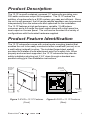
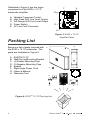
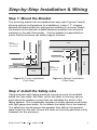
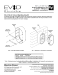
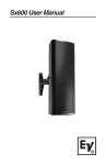
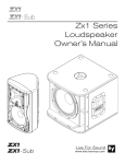
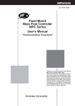
EVID 12.1P User Manual Electro-Voice® EVID 12.1P User Manual Table of Contents Product Description ................................................................................. 1 Product Feature Identification .................................................................. 1 Packing List ............................................................................................. 2 Step-by-Step Installation and Wiring ........................................................ 3 Step 1: Mount the Bracket ................................................................. 3 Step 2: Install the Safety Line ............................................................ 3 Step 3: Wire the Speaker .................................................................. 4 Step 4: Mount the Speaker to the Bracket ......................................... 4 For Corner Mounting ................................................................... 4 For Midwall Mounting .................................................................. 5 Mounting through a Suspended Ceiling Grid ............................... 6 Floor Mounting ............................................................................ 6 Step 5: Test System Operation .......................................................... 6 Safety Agency Compliance ...................................................................... 7 Maintenance ............................................................................................ 7 Appendix A: Warranty Statement ............................................................. 7 Appendix B: Installation Examples ........................................................... 8 Characteristics of all Subwoofers ...................................................... 9 Appendix C: Painting Process ............................................................... 10 Appendix D: Troubleshooting ................................................................. 11 Appendix E: Technical Specifiations ...................................................... 12 TOC Electro-Voice® EVID 12.1P User Manual Product Description The 12.1P is a self contained, powered 12" subwoofer providing over 300 watts continuous output to the speaker. The 12.1P makes the addition of a subwoofer to a EVID system very easy and efficient. Since the unit is self-powered, the full range satellite speakers can be powered independently from the subwoofer and optimized for the installation. The 12.1P features a high performance, variable, 12-dB/octave crossover and a full range line level output along with a high pass line level output on the rear panel. The unit can be mounted in a variety of configurations with the bracket hardware supplied. Product Feature Identification The 12.1P subwoofer comes with a dual-mode mounting bracket that enables the unit to be easily mounted at either a wall/wall (corner) or on a wall/ceiling (midwall) junction. The included forged steel eyebolt provides the installer a solid attachment point for a safety line. When properly anchored and supported, the 12.1P subwoofer may also be safely installed protruding just 2 3/4" down through a standard suspended ceiling grid. See installation instructions. Dual-mode mounting bracket Safety line attachment eyebolt Acoustic ports Amplifier panel Bracket clip mounting points EV® logo Figure 1: EVIDTM 12.1P Features (Front) Electro-Voice® EVID 12.1P User Manual Figure 2: EVIDTM 12.1P Features (Rear) 1 Illustrated in Figure 3 are the major components of the EVIDTM 12.1P subwoofer amplifier. A. B. C. D. E. A C B Variable Crossover Control High Pass XLR Line Level Output Full Range XLR Line Level Output Power Switch AC Line Cord Connector D E Figure 3: EVIDTM 12.1P Amplifer Panel Packing List Below is a list of parts included with the EVIDTM 12.1P subwoofer. The parts are illustrated in Figure 4. A. B. C. D. E. F. G. H. EVIDTM 12.1P Wall/Corner Mounting Bracket (4) Rubber Mounting Feet (2) Speaker Mounting Clips Eyebolt Right Angle Power Cord Owners Manual Warranty Card B A C D E F G H Figure 4: EVIDTM 12.1P Packing List 2 Electro-Voice® EVID 12.1P User Manual Step-by-Step Installation & Wiring Step 1: Mount the Bracket The mounting bracket can be installed two ways (see Figures 5 and 6), allowing optimal configurations for installations. Leave 1.5" of space between the bracket and the ceiling when installing in a corner! Attach the bracket to the wall with suitable fasteners screwed into structural members in the wall. Remember: It is the installers responsibility to insure that the structure can safely support the load. Use a mimimum of four screws Joist Wall Ceiling Bracket Top plate Stud Stud Figure 5: Corner Installation (Top View) Use a mimimum of four screws Wall Bracket Stud Wall Figure 6: Midwall Installation (Side View) Step 2: Install the Safety Line Using accepted safe rigging practices, secure one end of a suitable safety line (use cable, not chain, which will rattle) to a strong, secure point above the speaker, a point that can withstand the shock of the falling speaker. This is especially important in public spaces constructed with light gauge steel studs. Do not attach the safety line to the bracket! The safety line should prevent the speaker from falling if the bracket tears loose from the wall. Secure the other end to the eyebolt that is fully threaded into the enclosure. Electro-Voice® EVID 12.1P User Manual 3 Step 3: Wire the Speaker A typical wiring configuration is shown in Figure 7. It is highly advisable to support the unit while these connections are being made. When mounting the speaker in a corner mount configuration, a right angle XLR connector such as Neutrik #NC3MRC or equiv. is required for the signal connections (see Figure 7). Connect the line level signal from the mixer, pre amplifier or other source into the line input connector. Plug in the power cord and connect the unit to a standard 120VAC power source. The proper crossover setting is determined by the satellite speakers used. The following are general guidelines: Figure 7: Wiring Configuration S a t e llit e Speaker C ro s s o v e r S e t t in g 3 .2 11 0 Hz 4 .2 9 5 Hz 6 .2 8 0 Hz Adjust the crossover according to the chart above. Set the appropriate sub level before making the final mounting to the bracket. Step 4: Mount the Speaker to the Bracket First remove the two Phillips-head screws on the rear of the enclosure. Use the supplied eyebolt to mount one mounting clip to the top of the speaker as shown in Figure 8. Check to make sure that the wiring connections to the amplifier and the satellite speakers are correct and secure. For corner mounting Attach the four rubber mounting feet to the front side edges, and secure the safety line to the eyebolt. Lift the enclosure up to the ceiling and center it back it into the corner until it touches the bracket rungs, then carefully lower it so the top clip hooks over the top rung of the bracket (1). Insert one of the 3/8-16-thread Phillips-head screws through the remaining clip and, with the clip pointing up, thread the screw finger-tight into the lower mtg. hole on the enclosure (2, 3). Level the clip and tighten securely with a #3 right-angle Phillips screwdriver. Even though the 4 Electro-Voice® EVID 12.1P User Manual enclosure hangs from the top clip, always install the lower one to secure against possible disengagement of the top clip. Straighten the EV® logo and press firmly at its center to seat it securely into its mounting hole. 1 1 Rungs 2 3 Rungs This side towards wall 3 2 Figure 8: Corner Mounting Figure 9: Midwall Mounting For midwall mounting Attach the four rubber mounting feet inside the corners on the side of the enclosure that will be against the wall and attach the safety line to the eyebolt. Insert one of the 3/8-16-thread Phillips-head screws through the remaining clip and keep it within arms reach. Lift the enclosure up to the ceiling and bring its back into contact with the bracket rungs. Slide the enclosure sideways to engage the clip over one bracket rung (1) and, while holding it tight against both rungs, insert the 3/8-16-thread screw with its clip into the remaining mounting hole so the clip engages the remaining bracket rung (2, 3). Finger-tighten the screw and straighten the clip. The enclosure may now be released. It will slide down the rungs until the four rubber feet are snug against the wall. Using a #3 right-angle Phillips screwdriver, securely tighten the second Phillips-head screw. Gently rotate the EV® logo a quarter turn and press firmly at its center to seat it securely into its mounting hole. See Figure 9. Electro-Voice® EVID 12.1P User Manual 5 Mounting through a suspended ceiling grid On the rear of the enclosure install and tighten two 3/8-16-thread forged steel eyebolts (one is included) with a 3/8" flat washer under each. Cut two pieces of ordinary drop ceiling L angle (wall track) 23 3/4" long and screw them to the top and bottom of the enclosure with 3/4"-long sheet metal screws, as shown in Figure 10. Connect all of the wires and suspend the enclosure, face down, by the eyebolts in accordance with accepted safe rigging practice. Adjust the length of the rigging cables so the tips of the installed L angles just rest on the ceiling cross-tees. This stabilizes the enclosure from rocking. Trim the ceiling panel to fit the new opening(s) and drop into place. It is the installers responsibility to assure that the chosen rigging points are strong enough to support the load. Warning: Never try to install this speaker in a suspended ceiling without proper rigging support! Rigging cables L angle Ceiling tile Eyebolts Acoustic port Figure 10: Attach L Angles to Speaker Floor Mounting The EVID 12.1P may be placed directly on the floor in a corner or on its side along a straight wall by simply attaching the four rubber mounting feet to the side that will sit on the floor. Step 5: Test System Operation After all connections are made test the complete system operation. Appendix C on page 10 contains a troubleshooting guide to assist in locating a variety of speaker related problems. 6 Electro-Voice® EVID 12.1P User Manual Safety Agency Compliance The EVID 12.1P bracket system has successfully passed EIA 636 at a safety factor of 6:1. The bracket system is intended to support the EVID 12.1P only. Do not use it for any other purpose. Never set anything on, or hang anything from, the EVID 12.1P enclosure when using this bracket. For a copy of the model-specific CE Declaration of Conformity, contact Electro-Voice at the address listed at the end of this manual. Maintenance Your EVID system has been designed and manufactured to provide years of durability and reliable service. No routine maintenance is necessary. Units may be cleaned by wiping with a soft, damp cloth. Never use solvents or harsh cleaning agents of any kind. Appendix A: Warranty Statement Electro-Voice® Speakers and Speaker Systems are guaranteed against malfunction due to defects in materials or workmanship for a period of five (5) years from the date of original purchase. The Limited Warranty does not apply to burned voice coils or malfunctions such as cone and/or coil damage resulting from improperly designed enclosures. ElectroVoice® active electronics associated with the speaker systems are guaranteed for three (3) years from the date of original purchase. If such malfunction occurs during the specified period, the product will be repaired or replaced (at our discretion) without charge. The product will be returned to the customer prepaid. Exclusions and Limitations The Limited Warranty does not apply to: (a) exterior finish or appearance; (b) certain specific items described in the individual product-line statements below, or in the individual product sheet or owners manual; (c) malfunction resulting from use or operation of the product other than as specified in the product data sheet or owners manual; (d) malfunction resulting from misuse or abuse of the product; or (e) malfunction occurring at any time after repairs have been made to the product by anyone other than Electro-Voice® Service or any of its authorized representatives. Electro-Voice® EVID 12.1P User Manual 7 Obtaining Warranty Service To obtain warranty service, a customer must deliver the product, prepaid, to Electro-Voice® Service or to any of its authorized service representatives, together with proof of purchase of the product in the form of a bill of sale or receipted invoice. A list of authorized service representatives is available from Electro-Voice® Service at: 12000 Portland Avenue, Burnsville, MN 55337 Ph: (877) 863-4166 Incidental and Consequential Damages Excluded Product repair or replacement and return to the customer are the only remedies provided to the customer. Electro-Voice® shall not be liable for any incidental or consequential damages including, without limitation, injury to persons or property or loss of use. Some states do not allow the exclusion or limitation of incidental or consequential damages, so the above limitation or exclusion may not apply to you. Other Rights This warranty gives you specific legal rights, and you may also have other rights which vary from state to state. Appendix B: Installation Examples The EVID Series is a product family with the flexibility to fit the requirements of many different applications. Listed below are some suggested combinations for systems using the 12.1P with EVID full range speakers: • Rich, full-sounding low-level background music and paging in a quiet restaurant, office, or retail space: use two EVID 3.2s or C4.2s for each 12.1P installed. • 8 Moderate-level music and paging in a sports bar/restaurant or upbeat retail space: install two or four EVID 4.2s or C8.2s for each 12.1P used. Electro-Voice® EVID 12.1P User Manual • Higher-level foreground music in bass heavy applications such as dance floors, amusement arcades, or loud bars: use one pair of EVID 6.2s for each 12.1P. • For example, a large hotel might use eight 3.2s and two 12.1Ps in the dining room, eight 4.2s and two 12.1Ps in the lounge, four 6.2s with two 12.1Ps surrounding the dance floor, 6.2s around the pool, 6.2s or 4.2s with or without 12.1Ps in the lobby, and 3.2s in the corridors. Characteristics of All Subwoofers While subwoofers do radiate sound omni-directionally (in all directions) and the sound is generally non-localizable (one cant hear exactly where it comes from), subwoofer sound level still drops off the farther one moves from the subwoofer. The highest output and best room loading are accomplished with the subwoofer mounted in a corner at a threeboundary junction (wall/wall/ceiling or wall/wall/floor, an arrangement also referred to as 1/8 space). Mounting at a two-boundary junction (wall/ ceiling, or 1/4 space) produces three dB less output, and mounting in the middle of a room in the ceiling (1/2 space) reduces output still another three dB. Subwoofers produce large amounts of long wavelength low-frequency energy. Every object has its own resonant frequency, and long wavelengths tend to excite large objects (like walls, floors, doors and ceiling panels). Anything loose in or on a ceiling or wall will buzz or rattle as a subwoofers level is increased. Most of these can be isolated and fixed with small, strategically placed bits of foam tape. Others may require driving additional nails or screws and perhaps some caulking to dampen their sympathetic movement. Electro-Voice® EVID 12.1P User Manual 9 Appendix C: Painting Process 10 • Remove the four screws securing the front hatch and lift off the hatch panel. Carefully twist and lift off the EV® logo and set it aside. • The foam grille blocks are held in place by sharp pins protruding through the baffle board. Note the relative position of the foam and carefully lift the blocks off the pins. Mask around and over the amplifier panel with tape and heavy paper and tape a piece of heavy paper over the woofer. It is not necessary to remove any components. • Clean the cabinet, bracket and clips by rubbing with a lightly dampened cloth. Do not use abrasives such as sandpaper or steel wool. Never use gasoline, kerosene, acetone, MEK, paint thinner, harsh detergents, or other chemicals, as these agents may cause permanent damage to the enclosure. • After cleaning, apply two or more two thin coats of either latex or oil-based paint. Spraying is recommended, but a brush and small roller work very well. It is not necessary to paint all the way up to the woofer. Only the visible surfaces need to be painted: the hatch front and side edges, the exposed enclosure surfaces down to the hatch gaskets and about halfway under where the foam blocks sit. Likewise, the rear sides of the bracket and clips need not be painted. The hatch screw heads may be painted, if desired. • When the paint is thoroughly dry, carefully unmask everything. Replace the foam blocks, pressing them gently down onto the sharp pins. Replace the hatch cover and tighten the four screws. Locate the small center hole, properly orient the EV® logo, and press it firmly into place at its center to reseat it in the mounting hole. Electro-Voice® EVID 12.1P User Manual Appendix D: Troubleshooting Guide Problem 1. No sound Possible Cause(s) Action Amplifier Verify that that the line level signal cables XLR connector has been pushed all the way into the Low Level In jack on the amplifier panel. Turn the Power switch on and the volume up until you can hear sound emitting from the 12.1p subwoofer. If there is still no sound, the problem is with the line level signal. Line level signal Connect a known working powered test speaker to the line level signal from the mixer, pre amplifier or other source. If there is no sound, check that all of the electronics are on, the signal routing is correct, the source is active, the volume is on and so on. Fuse Carefully remove the fuse holder from the power cord input with the use of a flat head screwdriver. Inspect the fuse for any damage. Blown fuses will typically show a smoke-like blackening on the inside of the glass. If this is the problem, replace the fuse with a 4A/250V, 20mm x 5mm fuse. Only replace this fuse with the same type and rated fuse to reduce the risk of fire. 2. Poor low-frequency Speakers wired response out-of-polarity When two speakers are connected out of polarity (out of phase), the low frequencies will cancel each other acoustically. Carefully observe the wire markings or tracers on your full-range speaker wires. Verify that their amplifier (+) terminal is connected to the red speaker terminals and their amplifier (-) terminal is connected to the black speaker terminals. 3. Intermittent output such as crackling or distortion Check the low-level signal cable/XLR connector to make sure that it has been pushed all the way into the Low Level In amplifier panel jack. If crackling persists, remove the signal cable from the amplifier and its low-level signal source and check for a faulty connection between the connector and the cable. Make sure that all of the terminals on cable connectors have been properly soldered. Faulty connection/wiring If these suggestions do not solve your problem, contact your nearest Electro-Voice dealer or Electro-Voice distributor. Electro-Voice® EVID 12.1P User Manual 11 Appendix E: Technical Specifications Frequency Response (-10 dB): 42 Hz 160 Hz Max Calculated SPL1 @ 1M: 126 dB LF Amplifier Power: 650W 50ms Burst, 300W Continuous Line Input Sensitivity: LF Transducer: -12 dBu to 0 dBu for Full Output 12 (300 mm) High-Excursion Dual Voice-Coil Connectors: Line Inputs: Balanced Outputs: XLR XLR Power Requirement: 110-130 VAC, 50-60 Hz Enclosure Material: MDF, Steel Fastener Reinforced Included Accessories: Mounting Bracket and Hardware Dim (H x W x D): 16.25" x 23.0" x 12.0" (412 mm x 584 mm x 305 mm) Net Weight: 49.0 lbs (22.2 kg) 1 12 1/8 Space (Corner Mounting) @ 1 Meter Electro-Voice® EVID 12.1P User Manual Notes Electro-Voice® EVID 12.1P User Manual 13 U.S.A. and Canada: For customer orders, contact the Customer Service department at: 800/392-3497 Fax: 800/955-6831 For warranty repair or service information, contact the Service Repair Department at: 800/685-2606 For technical assistance, contact Technical Support at: 866/78-AUDIO Specifications subject to change without notice. All Other International Locations: 952-884-4051 Fax: 952-736-4212 www.electrovoice.com l Telex Communications, Inc. l Printed in U.S.A © Telex Communications, Inc. 2/2003 Part Number 38110-199 Rev A Electro-Voice® www.telex.com EVID 12.1P User Manual