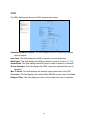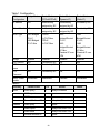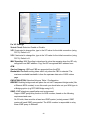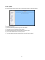
1
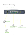
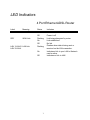
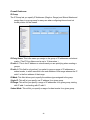
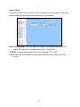
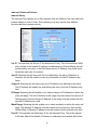
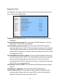
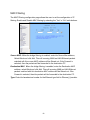
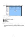
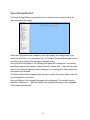
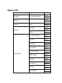
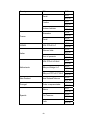
ADSL Broadband Router AR-6024 User’s Manual Table of Contents Specification................................................................................................................ 2 Package Contents ....................................................................................................... 5 Hardware Connecting.................................................................................................. 6 LED Indicators............................................................................................................. 7 General Setting ........................................................................................................... 8 One Page Setup--------------------------------------------------------------------------------- 12 Status ---------------------------------------------------------------------------------------------- 14 Router ......................................................................................................... 14 ADSL .......................................................................................................... 16 PPP............................................................................................................. 17 Advanced Setting ...................................................................................................... 22 ADMINISTRATION ----------------------------------------------------------------------------- 23 WAN............................................................................................................ 23 LAN............................................................................................................. 29 DNS ............................................................................................................ 31 NAT ............................................................................................................. 32 Port Forwarding .......................................................................................... 34 ADSL Configuration .................................................................................... 35 RIP Configuration........................................................................................ 36 Firewall ....................................................................................................... 37 Service Filtering .......................................................................................... 41 Diagnostic Test............................................................................................ 49 Router Table................................................................................................ 51 MAC Filtering .............................................................................................. 52 Security -------------------------------------------------------------------------------------------- 53 Admin Password ......................................................................................... 53 User Password............................................................................................ 54 Misc Configuration ...................................................................................... 55 System Log ................................................................................................. 57 Code Update............................................................................................... 58 Status ---------------------------------------------------------------------------------------------- 59 Router ......................................................................................................... 59 ADSL .......................................................................................................... 61 WAN Status................................................................................................. 62 ATM Status.................................................................................................. 63 TCP connections......................................................................................... 64 Learned MAC Table .................................................................................... 65 PPP Status.................................................................................................. 66 Save Settings/Reboot ................................................................................. 67 Appendix ................................................................................................................... 68 1 Specification 4-Port Ethernet ADSL Router Features ADSL Compliance ANSI T1.413 i2 ITU G.992.1 (G.dmt) Annex A, B ITU G.992.2 (G.lite) Maximum downstream rate of 8Mbps Maximum upstream rate of 1Mbps Dying Gasp (optional) ATM Protocols and Encapsulations PPP over ATM (RFC 2364) PPP over Ethernet (RFC 2516) Bridged/Routed Ethernet over ATM (RFC 1483) Classical IP over ATM (RFC 1577) ATM Forum UNI 3.1/4.0 PVC 10 PVCs (simultaneous and encapsulation independent) VPI/VCI range 0-255, 0-65536 Encapsulation hunting of up to 8 pre-defined VPI/VCI & encapsulation sets ATM AAL5 (Adaption Layer type 5) UBR & CBR OAM F4/F5 Bridging Functionality IEEE 802.1D (self learning transparent bridge) 256 MAC Addresses support PPP Half Bridge - No 3rd party PPPoE client software required Routing Functionality Static IP routing (configurable route table) RIPv2 (backward compatible with RIPv1) 2 DHCP server/client/relay agent PPP auto reconnect and configurable timeouts PPP auto reconnect on WAN access PPP Auto, PAP, and CHAP 128 character support for PPPx username/passwords DNS proxy NAT, NAPT & Dynamic NAPT ALG support (FTP, SMTP/POP3, ICMP, NNTP, RTSP, IRC, CuSeeMe, Telnet, Messenger, EPIC games, id games, Sierra studios games) Wild Card DMZ Virtual server (Port mapping) VPN pass through (IPSec - ESP Tunnel mode, L2TP, PPTP) Bridge filtering ICMP IGMP MAC Address Spoofing Auto VPI/VCI PPPoE/PPPoA detection Multiple PPP sessions per PVC Management HTTP client and server Password protection (2 levels) Configurable Web pages FTP server and client (for network upgrade) Local firmware upgrade via Web configuration pages Remote firmware upgrade via FTP client Restore to Factory defaults via Web or hardware reset 7 layer diagnostics with links to help pages System logging Inner pair / Outer pair / Auto-detection of RJ-11 Ethernet Features IEEE 802.3/802.3u auto-negotiation compliant Auto sense 10/100 Full or Half duplex mode Half duplex - back pressure flow control Full duplex - IEEE 802.3x flow control Crossover Detection and Auto Correction 3 Hardware LAN: 4-Port 10/100Base-T (RJ-45) ADSL: One Port (RJ-11) Power: 9VAC 800mA LED indicators: Power, Ready (Status), ADSL, LAN*4 Reset button Certification: FCC Part 15/Part 68, CE, LVD Application Diagram Internet 4 Package Contents ADSL Router CD-ROM containing Manual Ethernet Cable (CAT5 UTP Straight-Through) ADSL Cable (Standard telephone cable) USB Cable (Optional) Power Adapter Quick Installation Guide hardcopy 5 Hardware Connecting 4 Port Ethernet ADSL Router Factory Reset Splitter (optional and changes depending on country specification) RJ-45 Ethernet port connect Ethernet cable here RJ-11 ADSL port connect ADSL cable here 6 Power Adapter (9VAC/800mA) Power cord connect here LED Indicators 4 Port Ethernet ADSL Router Label Meaning Status Indicates PWR Power On Power is on WAN Link Off Flashing On Power is off Link being attempted by router. Link established Off Flashing No link Flashes when data is being sent or received on the LAN connection. On Indicates a link to your LAN or Network card is active. Indicates no link to LAN RDY LAN 1/ LAN 2/ LAN Link LAN 3/ LAN 4 Off 7 General Setting You can use the RJ 45 cable or the USB cable connect to the ADSL Router. Please see the connecting procedures as below: Move your cursor as following sequence Start \ Settings \ Control Panel and click Control Panel. Then double-click on the Network Connections In the LAN or High-Speed Internet window, right-click on icon corresponding to your network interface card (NIC) and select Properties.(This icon may be labeled Local Area Connection). In the General Tab of the Local Area Connection Properties menu. 8 Highlight Internet Protocol (TCP/IP) under “This connection uses the following items.” by click on it once. Click on the Properties button. Select Obtain an IP address automatically: by clicking once in the circle. Click OK button to confirm and save your changes, and the close the Control Panel. Release IP & Renew IP, then Check Default Gateway: 10.0.0.2 9 Launch your PC web browser and enter the URL: 10.0.0.2 In the User name/Password prompt, please type in admin/epicrouter as default. 10 Now you can start browsing the web through the ADSL device. 11 One Page Setup When working with wide area connections, the first thing you must do is to have the handle of the connection. Once you have the handle for a Connection you must define the PVC and protocol settings for it. LAN IP Address & Subnet Mask: The default is 10.0.0.2and 255.255.255.0 you can change it to another private IP address, such as 211.22.10.191 and 255.0.0.0. For most configurations it is recommended to leave it as default. Service Name: Enter the name of your ISP. This information is for identification purposes only. Username: Enter the username provided by your ISP. 12 Password: Enter the password provided by your ISP. Disconnect Timeout: Disconnect Timeout means the router will disconnect after being idle for a preset amount of time. WAN Type: Select type from the list. VC Settings VPI: If instructed to change this, type in the VPI value for the initial connection (using PVC 0). Default = 8. VCI: If instructed to change this, type in the VCI value for the initial connection (using PVC 0). Default = 35. Static IP Address: Enter the IP address provided by your ISP. such as 192.168.241.101. Subnet Mask: Set your Subnet Mask such as 255.255.255.0 BRIDGE Mode: Select Enable or Disable from the list. Note: Click the Submit button to save the settings in temporary memory. If you make changes the configurations. 13 Status Router The Home page shows the Firmware Version and WAN and LAN interface status. Firmware Version: This field displays the Firmware Version number. WAN: These fields display the IP Address, Subnet Mask, MAC Address for WAN interface. 14 LAN: These fields display the IP Address, Subnet Mask, MAC Address for LAN interface. Number of Ethernet devices connected to the DHCP server: This field displays the number of DHCP clients connected to the ADSL Router. It also shows the IP address and MAC address of the attached DHCP clients. 15 ADSL The ADSL Status page shows the ADSL physical layer status. Showtime Firmware Version: This field displays the ADSL data pump firmware version number. Line State: This field displays the ADSL connection process and status. Modulation: This field displays the ADSL modulation status for G.dmt or T1.413. Annex Mode: This field displays the ADSL Annex modes for Annex A or Annex B. Startup Attempts: This field displays the ADSL connection attempts after loss of showtime. Max Tx Power: This field displays the transmit output power level of the CPE. Co Vendor: This field displays the Central Office DSLAM vendor name. If available. Elaspsed Time: This field displays the time of the modem has been in operation. 16 PPP The PPP Status page shows the status of PPP for each PPP interface. See PPP. These fields display the following information on each PPP interface: Connection Name (user defined) Interface (PVC) Mode (PPPoE or PPPoA) Status (Connected or Not Connected) Packets Sent Packets Received Bytes Sent Byte Received Connect and Disconnect: Each PPP session can be individually controlled, simply enter the desired connection number into the “Connection #” field and select either connect or disconnect from the drop down menu and click on the “Execute” button. 17 WAN Configuration: The WAN configuration page allows the user to set the configuration WAN/ADSL ports. Per VC Settings Virtual Circuit: Selection Enable or Disable. VPI: If instructed to change this, type in the VPI value for the initial connection (using PVC 0). Default = 0. VCI: If instructed to change this, type in the VCI value for the initial connection (using PVC 0). Default = 0 MAC Spoofing: MAC Spoofing is developed to solve the scenario when the ISP only recognizes one MAC address. Copy the ISP-recognized MAC address here. ATM Service Category: UBR and CBR are supported from the ATM. 18 Bandwidth: Bandwidth setting takes effect only when the CBR is selected. The maximum available bandwidth is from the upstream data rate of ADSL status page. ENCAPSULATION: Selection follow as Table-1 Configuration BRIDGE: Enabling bridge mode will place the unit into Transparent bridge mode (like a Ethernet ADSL modem) to use this mode you should also set your WAN type to a Bridging option (e.g RFC1482 Bridge using LLC). IGMP: IGMP relay/proxy specification and environment: Support IGMP proxy/relay function for ADSL modem, based on the following requirement and case: On CO side, there must be at least one IGMP querier (router) present. IGMP querier will send IGMP query packet. The ADSL modem is responsible to relay these IGMP query to Ethernet. End-user multicast application device send IGMP report while receiving IGMP query or being activated by user, the ADSL modem should be responsible to proxy (that is, change source IP to ADSL modem’s WAN IP) the IGMP report to ADSL WAN side, include all PVCs. The same case is for IGMP leave packet. Not necessary to relay multicast routing between two ADSL PVCs or two interfaces in LAN side. Special purpose multicast packet (such as RIP 2 packet) should run without interference. 19 Table-1 Configuration WAN Configuration Bridge Mode Router Mode (PPPoA/PPPoE) Router Mode (Dynamic IP) Router Mode (Static IP) IP address N/A Automatically assigned by ISP Automatically assigned by ISP Provided by ISP Subnet Mask N/A Automatically assigned by ISP Automatically assigned by ISP Provided by ISP WAN Type 1483 Bridged IP LLC, 1483 Bridged IP VC-Mux PPPoA LLC/VC-Mux, PPPoE LLC/VC-Mux 1483 Bridged/Routed IP LLC, 1483 1483 Bridged/Routed IP LLC, 1483 Bridged/Routed VC-Mux, Classical IP over ATM Bridged/Routed VC-Mux, Classical IP over ATM Bridge Enabled Disabled Disabled Disabled PPP Service N/A Provided by ISP N/A N/A PPP User name N/A Provided by ISP N/A N/A PPP Password N/A Provided by ISP N/A N/A DHCP Client enable Unchecked Unchecked Checked Unchecked Action Notes Table-2 Rx Entity ADSL Ethernet Packet Class TTL IGMP query 1 Relay to Ethernet IGMP report 1 Ignore IGMP leave 1 Ignore General Multicast IP - Relay it to Ethernet. IGMP query 1 Ignore IGMP report 1 Relay to all ADSL PVC IGMP leave 1 Relay to all ADSL PVC General Multicast IP - Ignore 20 PPP: The current release supports multiple PPP sessions per PVC. The PPP configuration in the WAN configuration page is for the first PPP session for each PVC. The predefined PPP Account Name (Account ID) is “Simple PPP Account 0” for PVC0 and predefined PPP Connection Name is “Simple PPP Session 0” for PVC0. For the other PVC X, the predefined account name and connection name will be Simple PPP Account X and Simple PPP Session X. X is the PVC number from 1 to 7. It can support up to total of 16 PPP sessions, and each PVC can support up to 8 PPP sessions, the multiple PPP sessions may be configured with any combination over 8 PVCs. Service Name: The service name of PPP is required by some ISPs. If the ISP does not provide the Service Name, please leave it blank. Username: Your user name provided by your ISP. Password: Your password provided bye your ISP. Disconnect Timeout: The Disconnect Timeout allows the user to set the specific period of time to disconnect from the ISP. The default is 0, which means never disconnect from the ISP. MRU: Maximum Receive Unit indicates the peer of PPP connection the maximum size of the PPP information field this device can be received. The default value is 1492 and is used in the beginning of the PPP negotiation. In the normal negotiation, the peer will accept this MRU and will not send packet with information field larger than this value. MTU: Maximum Transmission Unit indicates the network stack of any packet is larger than this value will be fragmented before the transmission. During the PPP negotiation, the peer of the PPP connection will indicates its MRU and will be accepted. The actual MTU of the PPP connection will be set to the smaller one of MTU and the peer’s MRU. The default is value 1492. MSS: Maximum Segment Size is the largest size of data that TCP will send in a single IP packet. When a connection is established between a LAN client and a host in the WAN side, the LAN client and the WAN host will indicate their MSS during the TCP connection handshake. The default value is 1432. Automatic Reconnect: When it is checked, it will maintain the PPP connection all the time. If the ISP shut down the PPP connection, it will automatically reconnect PPP session. DHCP: Use Table-1 to configure a valid setting for each PVC. Host Name: Required by some ISPs. If the ISP does not provided the Host name, 21 please leave it blank. Note: Click the Submit button to save the settings in temporary memory. If you make changes the configurations. 22 Advanced Setting ADMINISTRATION The links under the ADMINISTRATION column are associated to the pages that represent the configurations of system and interfaces. Note: When the configurations are changed, please click the Save Setting and Reboot button. WAN The WAN configuration page allows the user to set the configuration for WAN/ADSL ports. 23 Per VC Settings Virtual Circuit: Selection Enable or Disable. VPI: If instructed to change this, type in the VPI value for the initial connection (using PVC 0). Default = 0. VCI: If instructed to change this, type in the VCI value for the initial connection (using PVC 0). Default = 0 MAC Spoofing: MAC Spoofing is developed to solve the scenario when the ISP only recognizes one MAC address. Copy the ISP-recognized MAC address here. ATM Service Category: UBR and CBR are supported from the ATM. Bandwidth: Bandwidth setting takes effect only when the CBR is selected. The maximum available bandwidth is from the upstream data rate of ADSL status page. ENCAPSULATION: Selection follow as Table-1 Configuration BRIDGE: Enabling bridge mode will place the unit into Transparent bridge mode (like a Ethernet ADSL modem) to use this mode you should also set your WAN type to a Bridging option (e.g RFC1482 Bridge using LLC). IGMP: IGMP relay/proxy specification and environment: Support IGMP proxy/relay function for ADSL modem, based on the following requirement and case: On CO side, there must be at least one IGMP querier (router) present. IGMP querier will send IGMP query packet. The ADSL modem is responsible to relay these IGMP query to Ethernet. 24 End-user multicast application device send IGMP report while receiving IGMP query or being activated by user, the ADSL modem should be responsible to proxy (that is, change source IP to ADSL modem’s WAN IP) the IGMP report to ADSL WAN side, include all PVCs. The same case is for IGMP leave packet. Not necessary to relay multicast routing between two ADSL PVCs or two interfaces in LAN side. Special purpose multicast packet (such as RIP 2 packet) should run without interference. 25 Table-1 Configuration WAN Configuration Bridge Mode Router Mode (PPPoA/PPPoE) Router Mode (Dynamic IP) Router Mode (Static IP) IP address N/A Automatically assigned by ISP Automatically assigned by ISP Provided by ISP Subnet Mask N/A Automatically assigned by ISP Automatically assigned by ISP Provided by ISP WAN Type 1483 Bridged IP LLC, 1483 Bridged IP VC-Mux PPPoA LLC/VC-Mux, PPPoE LLC/VC-Mux 1483 Bridged/Routed IP LLC, 1483 1483 Bridged/Routed IP LLC, 1483 Bridged/Routed VC-Mux, Classical IP over ATM Bridged/Routed VC-Mux, Classical IP over ATM Bridge Enabled Disabled Disabled Disabled PPP Service N/A Provided by ISP N/A N/A PPP User name N/A Provided by ISP N/A N/A PPP Password N/A Provided by ISP N/A N/A DHCP Client enable Unchecked Unchecked Checked Unchecked Action Notes Table-2 Rx Entity ADSL Ethernet Packet Class TTL IGMP query 1 Relay to Ethernet IGMP report 1 Ignore IGMP leave 1 Ignore General Multicast IP - Relay it to Ethernet. IGMP query 1 Ignore IGMP report 1 Relay to all ADSL PVC IGMP leave 1 Relay to all ADSL PVC General Multicast IP - Ignore 26 PPP: The current release supports multiple PPP sessions per PVC. The PPP configuration in the WAN configuration page is for the first PPP session for each PVC. The predefined PPP Account Name (Account ID) is “Simple PPP Account 0” for PVC0 and predefined PPP Connection Name is “Simple PPP Session 0” for PVC0. For the other PVC X, the predefined account name and connection name will be Simple PPP Account X and Simple PPP Session X. X is the PVC number from 1 to 7. It can support up to total of 16 PPP sessions, and each PVC can support up to 8 PPP sessions, the multiple PPP sessions may be configured with any combination over 8 PVCs. Service Name: The service name of PPP is required by some ISPs. If the ISP does not provide the Service Name, please leave it blank. Username: Your user name provided by your ISP. Password: Your password provided bye your ISP. Disconnect Timeout: The Disconnect Timeout allows the user to set the specific period of time to disconnect from the ISP. The default is 0, which means never disconnect from the ISP. MRU: Maximum Receive Unit indicates the peer of PPP connection the maximum size of the PPP information field this device can be received. The default value is 1492 and is used in the beginning of the PPP negotiation. In the normal negotiation, the peer will accept this MRU and will not send packet with information field larger than this value. MTU: Maximum Transmission Unit indicates the network stack of any packet is larger than this value will be fragmented before the transmission. During the PPP negotiation, the peer of the PPP connection will indicates its MRU and will be accepted. The actual MTU of the PPP connection will be set to the smaller one of MTU and the peer’s MRU. The default is value 1492. MSS: Maximum Segment Size is the largest size of data that TCP will send in a single IP packet. When a connection is established between a LAN client and a host in the WAN side, the LAN client and the WAN host will indicate their MSS during the TCP connection handshake. The default value is 1432. Automatic Reconnect: When it is checked, it will maintain the PPP connection all the time. If the ISP shut down the PPP connection, it will automatically reconnect PPP session. DHCP: Use Table-1 to configure a valid setting for each PVC. Host Name: Required by some ISPs. If the ISP does not provided the Host name, 27 please leave it blank. Note: Click the Submit button to save the settings in temporary memory. If you make changes the configurations. 28 LAN The LAN configuration page allows you to set the configuration for the LAN port. LAN IP Address & Subnet Mask: The default is 10.0.0.2 and 255.0.0.0 you can change it to another private IP address, such as 211.22.10.191 and 255.255.255.0. For most configurations it is recommended to leave it as default. DHCP Server: System Allocated. The DHCP address pool is based on LAN port IP address plus 12 IP address. For example, the LAN IP address is 10.0.0.2; the DHCP address pool is at the range of 10.0.0.3 to 10.0.0.14. User Defined: The DHCP address pool is at the range of User Defined Start Address and User Defined End Address. The maximum pool size can be 253 IP address:255 total IP address-1 broadcast address-1 LAN port IP address. 29 DHCP Gateway Selection: The default setting for the DHCP Gateway Selection is “Automatic”. The user can select the “User Defined” to specify “User Defined Gateway Address”. The DHCP server will issue the “ User Defined Gateway Address” to the LAN DHCP client. Lease time: The lease time is the amount of time of a network user will be allowed to connect with DHCP server. If all fields are 0, the allocated IP address will be effective forever. User mode: Under the Single User mode, the DHCP server only allocates one IP address to local PC. Under the Multiple User mode, the DHCP server allocates the IP addresses specified by the DHCP address pool. Ethernet Mode Setting: The Ethernet Mode Configuration page allows the user to set the LAN port into Auto Sense, 100 Mbps Full Duplex, 100 Mbps Half Duplex, 10 Mbps Full Duplex or 10 Mbps Half Duplex. Note: Click the Submit button to save the settings in temporary memory. If you make changes the configurations. 30 DNS The DNS Configuration page allows you to set the configuration of DNS proxy. Disable DNS Proxy: The LAN port does not process the DNS query message. For the DHCP requests from local PCs, the DHCP server will set the user-configured preferred DNS sever or alternate DNS server whichever is available as the DNS server. Then all DNS query messages will be directly sent to the DNS servers. Use Auto Discovered DNS Servers Only: The DNS proxy will store the DNS server IP addresses obtained from DHCP client or PPP into the table. And all DNS query messages will be sent to one of the dynamically obtained DNS servers. Use User Configured DNS Servers Only: The DNS proxy will use the user-configured preferred DNS server and alternate DNS server. And all DNS query message will be sent to one of DNS servers. Auto Discovery + User Configured: The DNS proxy’s table has all the IP addresses of dynamically obtained and user configured DNS servers. User Configuration: Place your primary and secondary DNS addresses here. 31 NAT The NAT Configuration page allows users to set the configuration for the Network Address Translation. The default setting is Dynamic NAPT. It provides dynamic Network Address Translation capability between LAN and multiple WAN connections, and the LAN traffic is routed to appropriate WAN connections based on the destination IP address and Route Table. This eliminates the need for the static NAT session configuration between multiple LAN clients and multiple WAN connections. When the Dynamic NAPT is chosen, there is no need to configure the NAT Session and NAT Session Name Configuration. The NAT option only maps single WAN IP address to the local PC IP address. It is peer-to-peer mapping. (1x1) for each WAN interface, only one local PC IP address can be associated with each WAN interface. Click the link Session Name Configuration to add the session name for WAN interface. The NAPT option only maps single WAN IP address to many local PCs IP address. (1xN). It is the multiple-mapping mechanism. For each WAN Interface, more than one local PC can be associated with one WAN Interface. Click the link Session Name Configuration to add the session name for WAN interface. Session Name: This field allows the user to select the session form the configured NAT Session Name Configuration. User’s IP: This field allows the user to assign the IP address to map the corresponding NAT/NAPT sessions. Session Name Status will be displayed at the middle of this page to show the corresponding Session Name with its IP address. 32 Number of NAT Configurations: This field displays the total number of NAT Sessions is entered. Available Sessions Status will be displayed at the end of this page to show all the Session Name with its WAN Interface. Interface: This field allows the user to choose specific WAN Interface (PVC or PPP Session) for NAT Session. Number of Session: This field displays the total number of NAT Sessions Name is entered. Note: Click the Submit button to save the settings in temporary memory. If you make changes the configurations. 33 Port Forwarding The Port Forwarding page allows the user define a port forwarding rule without using the firewall policy database definitions and apply it to the connection. Public Port: This field allows the user to enter the port number of Public Network. Private Port: This field allows the user to enter the port number of the Private Network. Host IP Address: This field allows the user to enter the private network IP address for the particular server. Well Known Ports: Port Protocol 21 FTP 23 Telnet 25 SMTP 43 Whois 53 DNS 69 TFTP 70 Gopher 79 Finger 80 HTTP 110 POP3 115 SFTP 161 SNMP 162 SNMP traps 34 ADSL Configuration The ADSL Configuration page allows users to set the configuration for ADSL protocols. Trellis: This field allows the user to enable or disable the Trellis Code. By default, it is always enabled. Handshake Protocol: This field allows the user to select the ADSL handshake protocol. Wiring Selection: This field allows the user to enter the wiring selection for the RJ-11. Tip/Rip is the default for the board without the inner/outer pair relay. Bit Swapping: This field allows the user to enable or disable the upstream bit swapping. Note: Click the Submit button to save the settings in temporary memory. If you make changes the configurations. 35 RIP Configuration The RIP System Wide Configuration page allows the user to set the configuration for each Interface (PVCs, PPP Sessions, USB and LAN). Interface: This field allows the user to choose the Interface (PVCs, PPP Sessions, USB and LAN), for the RIP to be configured. Enable: This field allows the user to Enable (Yes) or Disable (No) the Specified interface for RIP. Supplier: This field allows the user to select the Supplier Mode (RIP Transmit). Disabled: The supplier transmit is disabled. V1 BC: The supplier transmits in RIPv1 Broadcast. V2 BC: The supplier transmits in RIPv2 Broadcast. V2 MC: The supplier transmits in RIPv2 Multicast. Listener: This field allows the user to select the Listener Mode (RIP Receive). V1: The listener receives the RIPv1 only. V2: The listener receives the RIPv2 only. V1+V2: This listener receives the both RIPv1 and RIPv2. Supplier and Listener are based on section 4.1 “Compatibility Switch” in RFC 1723. Current RIP Settings: This field displays the each interface’s RIP status. Note: Click the Submit button to save the settings in temporary memory. If you make changes the configurations. 36 Firewall The Firewall page allows users to configure various database/firewall options and Inbound/Outbound policies for controlling Inbound/Outbound traffic. Firewall: This field allows the user to Disabled or Enabled Firewall. Note: Click the Submit button to save the settings in temporary memory. If you make changes the configurations. Protection Policy IP Spoofing checking: IP spoofing is when an unauthorized user inserts the IP address of an authorized user into the IP packets in order to gain access to a network. Selecting this option will allow the firewall to check for and filter out this discrepancy. 37 Ping of Death checking: Ping of Death is a type of DoS attack that uses a malformed ICMP data packet that contains unusually large amounts of data that causes TCP/IP to crash or behave irregularly. Enabling this will allow the firewall to filter out packets containing Ping of Death properties. Land Attack checking: Land attack is a type of DoS attack that works by sending a spoofed packet containing the same source and destination IP address and port (the victim’s IP address). This packet contains a connection request, resulting in a handshake process. At the end of the handshake, the victim sends out an ACK (ACKnowledge) request. Since the source and the destination are the same, the victim receives the ACK request it just sent out. The received data does not match what the victim is expecting, so it retransmits the ACK request. This process repeats until the network crashes. Enabling the will allow the firewall to filter out possible Land Attack packets. Reassembly Attack checking: Reassembly Attack is a type of DoS attack that exploits the weakness of the IP protocol reassembly process. As discussed earlier in this user guide, packets undergo fragmentation when they exceed a certain maximum size. Certain criteria define the packet fragmentation process so that packets can be reassembled properly. In reassembly attack, the sub-packets have malformed criteria (fragment offset), which can easily cause a system to crash, freeze, or reboot. Enable this option to check for and filter out Reassembly Attack packets. SYN Flooding checking: Syn flooding is a type of DoS attack that is accomplished by not sending the final acknowledgement to the receiving server’s SYN-ACK (SYN chronize-ACKnowledge) in the final part of the handshake process. This causes the serve to keep signaling until it is timed out. When a flood (many) of these attacks are sent simultaneously, the server will probably overload and crash. Enable SYN Flooding checking to filter out possible SYN flood packets. ICMP Redirection checking: Also known as an ICMP storm attack or smurf attack, ICMP redirection is another form of DoS. This attack is performed by sending ICMP echo requests to a broadcast network node. The return IP address is spoofed and replaced by the victim’s own address, causing it to send the request back to itself. This causes the broadcast address to send it out to all the network nodes in the broadcast area (usually the entire LAN). In turn, all those recipients resend it back to the broadcast. The process repeats itself, gaining more amplitude through each iteration and eventually causing a traffic overload and crashing the network. Enable ICMP Redirection checking to filter out packets 38 containing the threat. Source Routing checking: Source routing gives the sender of a packet the ability to determine the exact route that an IP packet takes to get to the destination. However, source routing can be used for malicious reasons. Using a source routed packet, the sender could find out important information about nodes in a network, making it easy to exploit any weakness. Enabling Source Routing checking will cause the firewall to filter out any packet with Source Routing properties. WinNuke Attack checking: WinNuke exploits a large networking bug found in Windows 95 and NT. WinNuke sends erroneous OOB (Out-of Band) data that Windows is unable to process, causing the target computer to crash. Enable this if you are running an early (95 or NT) version of Windows that is vulnerable to this attack. Note: Click the Submit button to save the settings in temporary memory. If you make changes the configurations. 39 Hacker Log This page allows you to configure which Protection Policy (see previous section) violations to log for admin viewing. Alert Log: Enable/ Disable for SYN Flooding, Ping of Death, IP Spoofing, and WinNuke (all of these are explained in the previous section). Enable to log violations of individual policies. General Log Deny Policies: Enabling this will add Deny Policy violations to the log. Allow Policies: Enabling this will add Allow Policy acceptances to the log. Log Frequency: This field lets you specify how many records to keep of each event. Default is 100. Range for Log Frequency Field is 1-65535. Note: Click the Submit button to save the settings in temporary memory. If you make changes the configurations. 40 Service Filtering Service Filtering allows you to disable service request from certain sources. Note: Click the Submit button to save the settings in temporary memory. If you make changes the configurations. 41 Firewall Databases: IP Group The IP Group lets you specify IP Addresses (Single or Range) and Subnet Masks and assign them to a group name for easy use when configuring inbound and out bound policies for the firewall. IP Entry Name: This is the name you assign to the group of IP addresses and subnet masks. (The IP Entry Name can be up to 19 characters.) IP addr. 1: This is the IP address or subnet mask you are specifying when creating a groups. IP addr. 2: This field is only active if you select to group a range of IP addresses or subnet masks, in which case this is the end address of that range whereas the IP addr 1 is the first address of that range. IP/Mask: This field allows you to specify the address type assigned to the group. Single IP: This will let you specify one IP address for a given group. IP Range: This will let you specify a range of IP addresses for a given group, starting with IP addr 1 and ending with IP addr 2. Subnet Mask: This will let you specify a range of subnet masks for a given group. 42 Service Group The Service Group lets you specify a Port and assign it to a group name for easy use when configuring inbound and outbound policies for the firewall. Service Entry Name: This is the name you assign to the group containing the port number. (The Service Entry Name can be up to 19 characters.) TCP/UDP: This specifies whether the port goes through TCP or UDP. Port #: This is the port number associated with the group name. Range for Port # 1-65535. 43 Time Window The Time Window lets you specify certain time periods and assign them to a group name for easy use when configuring inbound and outbound policies for the firewall. Time Window Name: This is the name you assign to the group that is given the time designation. (The Time Window Name can be up to 19 characters.) Time Period: This field allows you to specify the time period for both start time and end time by selecting the day, hour, minute, and AM/PM. 44 Inbound/ Outbound Policies: Inbound Policy The Inbound Policy allows you to filter inbound (from the WAN into the user side LAN) packets based on a set of rules. This enables you to deny access from different sources and thus increase security. Src IP: This specifies the Source IP for the Inbound Policy. This is the external (WAN side, outside of the firewall) IP address or addresses and Subnet Masks that will be affected by the policy. In this field there are two IP Address entry fields and a dropdown menu has four options: Any IP: Selecting this will cause all IPs to be affected by the policy. When this is selected, you will be unable to enter any information into the IP Address entry fields. Single IP: Selecting this will cause only one IP Address to be affected by the policy. This IP Address will need to be specified by the user in the first IP Address entry field. IP Range: Selecting this will enable you to select a range of IP Addresses to which the policy will apply. The first IP Address in the range must be entered into the first IP Address entry field and the last IP Address in the range must be entered into the second IP Address entry field. Mask Range: Selecting this will enable you to select a network to which the policy will apply. The Network IP Address must be entered into the first entry field and the Subnet Mask of Network IP address must be entered into the second entry field. Dest IP: This specifies the Destination IP for the Inbound Policy. This is the internal (LAN side, behind the firewall) IP address or addresses and network that will be 45 affected by the policy. See Src IP above for configuration detail. Src Port: This specifies the Source Port for the Inbound Policy. This is the external (WAN side, outside of the firewall) port(s) that will be affected by the policy. In this field, there are two port entry fields and a dropdown menu. The dropdown menu has four options: Any Port: Selecting this will cause all Ports to be affected by the policy. When this is selected, you will be unable to enter any information into the Port entry fields. Single Port: Selecting this will cause only one Port to be affected by the policy. This port will need to be specified by the user in the first Port entry field. Port Range: Selecting this will enable you to select a range of Ports to which the policy will apply. The first Port in the range must be entered in the first Port entry field and the last Port in the range must be entered in the second Port entry field. Safe Ports: Any port greater than 1024 (1025-65535) is considered a safe port. Dest Port: This specifies the Destination Port for the Inbound Policy. This is the internal (LAN side, behind the firewall) Port that will be affected by the policy. See Src Port above for configuration detail. Transport Protocol: This specifies the Transport/ Transfer protocol for the policy. The following protocol options are available: All, TCP, UDP, ICMP, AH, ESP and GRE. Filtering Action: This specifies what action the policy takes: Allow: Selecting this will cause the policy to allow packet transfer from the Src IP through the Src Port to travel through the Dest Port to the Dest IP. All of these are specified above and must be configured by the user. Deny: Selecting this will cause the policy to deny packet transfer from the Src IP through the Src Port to travel through the Dest Port to the Dest IP. All of these are specified above and must be configured by the user. Time Window Filtering: This field allows you to select a certain time frame from the Time Group in which this policy will be active. DB: Short for Database, this field allows you to select a user-defined IP Group for the Src IP and Dest IP fields and user-defined Service Group for the Dest Port. User-defined IP and Service Groups are created in IP Group and Service Group pages. 46 Outbound Policy The Outbound Policy allows you to filter outbound (from the user side LAN to the WAN) packets based on a set of rules. This enables you to deny access to different sources and thus increase security. Src IP: This specifies the Source IP for the Outbound Policy. This is the internal (LAN side, behind the firewall) IP address or addresses and Subnet Mask(s) that will be affected by the policy. In this field there are two IP Address entry fields and a dropdown menu has four options: Any IP: Selecting this will cause all IPs to be affected by the policy. When this is selected, you will be unable to enter any information into the IP Address entry fields. Single IP: Selecting this will cause only one IP Address to be affected by the policy. This IP Address will need to be specified by the user in the first IP Address entry field. IP Range: Selecting this will enable you to select a range of IP Addresses to which the policy will apply. The first IP Address in the range must be entered into the first IP Address entry field and the last IP Address in the range must be entered into the second IP Address entry field. Mask Range: Selecting this will enable you to select a network to which the policy will apply. The Network IP Address must be entered into the first entry field and the Subnet Mask of Network IP address must be entered into the second entry field. Dest IP: This specifies the Destination IP for the Outbound Policy. This is the external (WAN side, outside of the firewall) IP address or addresses and network that will be affected by the policy. See Src IP above for configuration detail. 47 Src Port: This specifies the Source Port for the Outbound Policy. This is the internal (LAN side, behind firewall) port(s) that will be affected by the policy. In this field, there are two port entry fields and a dropdown menu. The dropdown menu has four options: Any Port: Selecting this will cause all Ports to be affected by the policy. When this is selected, you will be unable to enter any information into the Port entry fields. Single Port: Selecting this will cause only one Port to be affected by the policy. This port will need to be specified by the user in the first Port entry field. Port Range: Selecting this will enable you to select a range of Ports to which the policy will apply. The first Port in the range must be entered in the first Port entry field and the last Port in the range must be entered in the second Port entry field. Safe Ports: Any port greater than 1024 (1025-65535) is considered a safe port. Dest Port: This specifies the Destination Port for the Outbound Policy. This is the external (WAN side, outside of the firewall) Port that will be affected by the policy. See Src Port above for configuration detail. Transport Protocol: This specifies the Transport/ Transfer protocol for the policy. The following protocol options are available: All, TCP, UDP, ICMP, AH, ESP and GRE. Filtering Action: This specifies what action the policy takes: Allow: Selecting this will cause the policy to allow packet transfer from the Src IP through the Src Port to travel through the Dest Port to the Dest IP. All of these are specified above and must be configured by the user. Deny: Selecting this will cause the policy to deny packet transfer from the Src IP through the Src Port to travel through the Dest Port to the Dest IP. All of these are specified above and must be configured by the user. Time Window Filtering: This field allows you to select a certain time frame from the Time Group in which this policy will be active. DB: Short for Database, this field allows you to select a user-defined IP Group for the Src IP and Dest IP fields and user-defined Service Group for the Dest Port. User-defined IP and Service Groups are created in IP Group and Service Group pages. 48 Diagnostic Test The Diagnostic Test page shows the test results for the physical layer and protocol layer for both LAN and WAN sides. Testing Ethernet LAN Connection: This test checks the Ethernet LAN interface connection. Testing ADSL Synchronization: This test checks the ADSL showtime. If this test returns FAIL, all other tests will be skipped. Test ATM OAM segment Loop Back: This test sends ATM OAM F5 Segment loop-back request cells to the CO. This test will pass if response cell is received. Some service providers might not support this test. If this test fails consistently and the ADSL modem does not seem to be working, make sure the VPI and VCI are configured correctly. Test ATM OAM End-to-End Loop Back: This test sends ATM OAM F5 End to End loop back request cells to the CO. This test will pass if response cell is received. Some service providers might not support this test. If this test return FAIL consistently and the ADSL modem does not seem to be working, make sure the VPI and VCI are configured correctly. Test Ethernet Connect to ATM: This test checks the ATM AAL5 module is loaded correctly. Test PPP Layer Connection: This test checks the PPP authentication. Test IP Connect to PPP: This test checks a valid IP address assigned from the service provider. Please note that on some ADSL services this test may fail despite the fact that you have connected correctly. 49 Ping Primary DNS: This test checks the primary DNS can be reached through pin request. Query DNS for www.conexant.com: This test checks the host name can be resolved to IP address though domain name servers. Ping www.conexant.com: This test checks the specified host can be reached through pin request. 50 Router Table The Router Table page displays routing table and allows the user to manually enter the routing entry. The routing table will display the routing status of Destination, Netmask, Gateway and Interface. The interface br0 means the USB interface; Io0 means the loopback interface and ppp1 means the PPP interface. The Gateway is the learned Gateway. Note: Click the Submit button to save the settings in temporary memory. If you make changes the configurations. 51 MAC Filtering The MAC Filtering configuration page allows the user to set the configuration of IP filtering. Enable and Disable MAC filtering by selecting the “Yes” or “No” radio buttons. Source MAC: When the bridge filtering is enabled, enter the Source Mac address, Select Block and click Add. Then all incoming WAN and LAN Ethernet packets matched with this source MAC address will be filtered out. If the Forward is selected, then the packets will be forwarded to the destination PC. Destination MAC: When the bridge filtering is enabled, enter the Destination MAC address, select Block and click Add. Then all incoming WAN and LAN Ethernet packets matched with this destination MAC address will be filtered out. If the Forward is selected, then the packets will be forwarded to the destination PC. Type: Enter the hexadecimal number for the Ethernet type field in Ethernet_II packets. 52 Security The links under Security are only to be accessed and configured, when it is login with administrator login name and password. Admin Password The Admin Password Configuration page allows the user to set the password for administrator. User Name: admin Password (default): epicrouter Note: Click the Submit button to save the settings in temporary memory. If you make changes the configurations. 53 User Password The User Password Configuration page allows the Admin user to set the password for the general user. When logged in as a general user you can view the basic status. User Name: user Password (default): password Note: Click the Submit button to save the settings in temporary memory. If you make changes the configurations. 54 Misc Configuration The Miscellaneous Configuration allows the user to set all the miscellaneous configurations. HTTP server access: This field allows the user to configure the Web pages can be accessed from. ALL: When this field is checked, it allows both WAN and LAN access to the Web pages. Restricted LAN: This field allows the Web pages access from LAN side. Restricted WAN Specified IP & Subnet Mask: This field allows the Web access from WAN side with a specify IP and Subnet Mask. HTTP server port: This field allows the user to specify the port of the Web access. 55 FTP server: This field allows the user to Enable or Disable the FTP connection. If you want FTP access from the WAN side you must ensure there are no port forwards for port 21. TFTP server: This field allows the user to Enable or Disable the TFTP connection. DMZ: A DMZ (De-Militarized Zone) is added between a protected network and an external network, in order to provide an additional layer of security. When there is a suspected packet coming from WAN, the firewall will forward this packet to the DMZ host. DMZ Host IP: The IP address of the DMZ host at LAN side. DHCP Relay: If it is enabled, the DHCP requests from local PCs will forward to the DHCP server runs on the WAN side of a network. To have this function working properly, please disable the NAT to run on router mode only, disable the DHCP server on the LAN port, and make sure the routing table has the correct routing entry. DHCP Target IP: The DHCP server runs on WAN side. IGMP Proxy: Here is the global setting for IGMP Proxy. If it is enabled, then the enabled IGMP Proxy on WAN PVCs will be working. Otherwise, no WAN PVC can have IGMP Proxy working on it. PPP connect on WAN access: If it is enabled, the PPP session will be automatically established when there is packet wants to go out the WAN. PPP Half Bridge: When the PPP Half Bridge is enabled, only one PC is able to access the Internet and the DHCP server will duplicate the WAN IP address from the ISP to the local client PC. Only the PC with the WAN IP address can access the Internet. This function should only be used if one computer will be allowed to connect to the internet (E.G a Software firewall computer or Proxy server). Note: Click the Submit button to save the settings in temporary memory. If you make changes the configurations. 56 System Log The System Log page shows the events triggered by the system. To clear the System Log simply click on the Clear Log button. Note: Click the Submit button to save the settings in temporary memory. If you make changes the configurations. 57 Code Update The code Update page allows the user to upload new firmware to the ADSL Router. To upload new firmware: 1. Download the latest firmware image from the website. 2. Save the file to your Desktop or other location. 3. Select the Browse button and locate the file saved in step 2. 4. Click on the Update button to start the process. 5. Once the upgrade has been completed the router will need to reboot. 58 Status Router The Home page shows the Firmware Version and WAN and LAN interface status. Firmware Version: This field displays the Firmware Version number. WAN: These fields display the IP Address, Subnet Mask, MAC Address for WAN interface. LAN: These fields display the IP Address, Subnet Mask, MAC Address for LAN interface. Number of Ethernet devices connected to the DHCP server: This field displays the 59 number of DHCP clients connected to the ADSL Wireless Router. It also shows the IP address and MAC address of the attached DHCP clients. 60 ADSL The ADSL Status page shows the ADSL physical layer status. Showtime Firmware Version: This field displays the ADSL data pump firmware version number. Line State: This field displays the ADSL connection process and status. Modulation: This field displays the ADSL modulation status for G.dmt or T1.413. Annex Mode: This field displays the ADSL Annex modes for Annex A or Annex B. Startup Attempts: This field displays the ADSL connection attempts after loss of showtime. Max Tx Power: This field displays the transmit output power level of the CPE. Co Vendor: This field displays the Central Office DSLAM vendor name. If available. Elaspsed Time: This field displays the time of the modem has been in operation. 61 WAN Status The WAN Status page shows the information and status of WAN PVCs. WAN: These fields display the IP Address, Subnet Mask and MAC Address for the WAN (ADSL) interface. Use the Virtual Circuit selection to selection different PVC for status display. 62 ATM Status The ATM Status page shows all the statistics information of ATM cells. Reset Counters: This button allows user to reset the ATM Status counter. 63 TCP connections The TCP Status page shows the statistics for all TCP connections. 64 Learned MAC Table The Learned MAC Table page shows the current learned Bridge MAC table. Aging Timeout: This field allows the user to enter the update period for the MAC table. Note: Click the Submit button to save the settings in temporary memory. If you make changes the configurations. 65 PPP Status The PPP Status page shows the status of PPP for each PPP interface. See PPP. These fields display the following information on each PPP interface: Connection Name (user defined) Interface (PVC) Mode (PPPoE or PPPoA) Status (Connected or Not Connected) Packets Sent Packets Received Bytes Sent Byte Received Connect and Disconnect: Each PPP session can be individually controlled, simply enter the desired connection number into the “Connection #” field and select either connect or disconnect from the drop down menu and click on the “Execute” button. 66 Save Settings/Reboot The Save Settings/Reboot page allows users to save the new configuration to the flash and reboot the system. When the configurations are changed via the Web pages, the settings need to be saved into the flash, so it is necessary to go to this Save Settings/Reboot page to save and reboot the system for the changes to be taken effect. During the Save and Reboot, the following Web page will be displayed “Your setting are being saved and the modem is being rebooted. Please wait…. After the Save and Reboot, the following Web page will be displayed “Your setting have been saved and the modem has rebooted.” The Reboot without Saving page allows the user to reboot the system without save the new configuration to the flash. During the Reboot, the following Web page will be displayed “The modem is being rebooted. Please wait….” After the Reboot, the following Web page will be displayed “The modem has rebooted”. 67 Appendix Country ISP Australia All Internet providers PVC VPI:8 VCI:35 VPI:0 Belgium Canada VCI:33 Telus Cybercity Danmark Tiscali 1 & 1 Internet DSL AOL DSL Arcor DSL Freenet DSL Fireline networks Deutschland GMX Internet Hansenet Netcologne Schlund Snafu ADSL 68 VPI:0 VCI:35 VPI:8 VCI:35 VPI:8 VCI:35 VPI:1 VCI:32 VPI:1 VCI:32 VPI:8 VCI:35 VPI:1 VCI:32 VPI:1 VCI:32 VPI:1 VCI:32 VPI:8 VCI:35 VPI:8 VCI:35 VPI:1 VCI:35 VPI:1 VCI:32 Country ISP Tiscali PVC VPI:1 VCI:32 T-online Anderer Anbieter Wannadoo France Tiscali ISRAEL KPN PPPoE LLC Telecom Italia Italian Rest oil presente KPN PPPoA VC-MuX Netherlands BBeyond Bridge LLC BBeyond PPPoA VC-MuX New Zealand New Zealand Telecom Portugal Todos os apresentador Albura Spanish Colt Teeccom Earth 69 VPI:1 VCI:32 VPI:1 VCI:32 VPI:8 VCI:35 VPI:8 VCI:35 VPI:8 VCI:48 VPI:8 VCI:35 VPI:8 VCI:35 VPI:8 VCI:48 VPI:0 VCI:33 VPI:0 VCI:35 VPI:0 VCI:100 VPI:0 VCI:35 VPI:1 VCI:32 VPI:0 VCI:35 VPI:8 VCI:32 Country ISP Eresmas PVC VPI:8 VCI:35 Jazztel Ola Internet Retevision Terra Spanish Tiscali Telefornica Telepac Uni2 Ya.com Wanadoo Island ssimi Suomi Landssimi Vortex Switserland Alle anbieter Sverige Skanova 70 VPI:8 VCI:35 VPI:8 VCI:35 VPI:0 VCI:35 VPI:8 VCI:32 VPI:1 VCI:32 VPI:8 VCI:32 VPI:8 VCI:35 VPI:1 VCI:33 VPI:8 VCI:32 VPI:8 VCI:32 VPI:0 VCI:35 VPI:8 VCI:48 VPI:8 VCI:48 VPI:1 VCI:32 VPI:8 VCI:35 Country ISP Hinet Seednet United Kingdom VPI:0 VCI:33 Taiwan United Arab Emirates PVC VPI:0 VCI:33 Etisalat Classical IP Single VPI:8 User VCI:35 Etisalat Classical IP for Business British Telecom 71 VPI:8 VCI:35 VPI:0 VCI:38