1
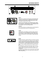
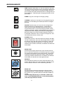
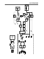
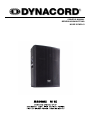
OWNER‘S MANUAL
BEDIENUNGSANLEITUNG
MODE D‘EMPLOI
CONTENTS
IMPORTANT SAFETY INSTRUCTIONS
IMPORTANT SERVICE INSTRUCTIONS
DESCRIPTION
UNPACKING & WARRANTY
CONTROLS
INPUT / OUTPUT
LEVEL
MODE
STATUS ANZEIGEN
POWER SCHALTER
NETZEINGANG
SPECIFICATIONS / TECHNISCHE DATEN
DIMENSIONS / ABMESSUNGEN
BLOCK DIAGRAM
.......................
.......................
.......................
.......................
.......................
.......................
.......................
.......................
.......................
.......................
.......................
.......................
.......................
.......................
3
3
4
4
5
5
5
5
6
6
6
19
20
21
WICHTIGE SICHERHEITSHINWEISE
WICHTIGE SERVICEHINWEISE
BESCHREIBUNG
AUSPACKEN & GARANTIE
BEDIENELEMENTE
INPUT / OUTPUT
LEVEL
MODE
STATUS ANZEIGEN
POWER SCHALTER
NETZEINGANG
SPECIFICATIONS / TECHNISCHE DATEN
DIMENSIONS / ABMESSUNGEN
BLOCK DIAGRAM
.......................
.......................
.......................
.......................
.......................
.......................
.......................
.......................
.......................
.......................
.......................
.......................
.......................
.......................
9
9
10
10
11
11
11
11
12
12
12
19
20
21
INHALT
MATIÈRES
IMPORTANTES INFORMATIONS DE SÉCURITÉ
INSTRUCTIONS DE RÉPARATION IMPORTANTES
DESCRIPTION
DÉBALLAGE ET GARANTIE
CONTROLES
ENTRÉE (INPUT / SORTIE (OUTPUT
NIVEAU (LEVEL
MODE
CONTROLES
INTERRUPTEUR SECTEUR (POWER)
SPECIFICATIONS
DIMENSIONS
BLOCK DIAGRAM
2
.......................
.......................
.......................
.......................
.......................
.......................
.......................
.......................
.......................
.......................
.......................
.......................
.......................
15
15
16
16
17
17
17
17
18
18
19
20
21
IMPORTANT SAFETY INSTRUCTIONS
The lightning flash with arrowhead symbol, within an
equilateral triangle is intended to alert the user to the
presence of uninsulated „dangerous voltage“ within
the product’s enclosure that may be of sufficient
magnitude to constitute a risk of electric shock to
persons
1.
2.
3.
4.
5.
6.
7.
8.
9.
10.
11.
The exclamation point within an equilateral
triangle is intended to alert the user to
the presence of important operating and
maintance (servicing) instructions in the
literature accompanying the appliance.
Read these instructions.
Keep these instructions.
Heed all warnings.
Follow all instructions.
Do not use this apparatus near water. Do not expose this apparatus to dripping or splashing and
ensure that no objects filled with liquids, such as vases, are placed on this apparatus.
Clean only with a dry cloth.
Do not block any of the ventilation openings. Install in accordance with the manufactures instructions.
Do not install near any heat sources such as radiators, heat registers, stoves, or other apparatus
(including amplifiers) that produce heat.
Only use attachments/accessories specified by the manufacturer.
Refer all servicing to qualified service personnel. Servicing is required when the apparatus has been
damaged in any way, such as power-supply cord or plug is damaged, liquid has been spilled or
objects have fallen into the apparatus, the apparatus has been exposed to rain or moisture, does not
operate normally, or has been dropped
To completely disconnect mains power from this apparatus, the power supply cord must be
unplugged.
Caution: Do not exceed the marked rating of the Mains Output.
Example: If each additional unit is rated 3A, a maximum of 3 units can be connected for a total of 9A.
For US and CANADA only:
1.
2.
3.
Do not defeat the safety purpose of the grounding-type plug. A grounding type plug has two blades and a third
grounding prong. The wide blade or the third prong are provided for your safety. When the provided plug does not fit
into your outlet, consult an electrican for replacement of the absolete outlet.
Protect the power cord from being walked on or pinched particularly at plugs, convenience receptacles,
and the point where they exit the apparatus.
Unplug this apparatus during lightning storms or when unused for long periods of time.
IMPORTANT SERVICE INSTRUCTIONS
CAUTION:
1.
2.
3.
4.
5.
6.
7.
8.
These servicing instructions are for use by qualified personnel only. To reduce
the risk of electric shock, do not perform any servicing other than that ontained
in the Operating Instructions unless you are qualified to do so. Refer all ervicing
to qualified service personnel.
Security regulations as stated in the EN 60065 (VDE 0860 / IEC 65) and the CSA E65 - 94 have to
be obeyed when servicing the appliance
Use of a mains separator transformer is mandatory during maintenance while the appliance is
opened, needs to be operated and is connected to the mains
Switch off the power before retrofitting any extensions, changing the mains voltage or the output voltage.
The minimum distance between parts carrying mains voltage and any accessible metal piece (metal
enclosure), respectively between the mains poles has to be 3 mm and needs to be minded at all times.
The minimum distance between parts carrying mains voltage and any switches or breakers that are not
connected to the mains (secondary parts) has to be 6 mm and needs to be minded at all times.
Replacing special components that are marked in the circuit diagram using the security symbol (Note) is
only rmissible when using original parts.
Altering the circuitry without prior consent or advice is not legitimate.
Any work security regulations that are applicable at the location where the appliance is being serviced
have to be strictly obeyed. This applies also to any regulations about the work place itself.
All instructions concerning the handling of MOS - circuits have to be observed.
NOTE:
SAFETY COMPONENT ( MUST BE REPLACED BY ORIGINAL PART )
3
DESCRIPTION
Congratulations! Your new DYNACORD MADRAS M15 is an active loudspeaker cabinet
incorporating state-of-the art technology.
The MADRAS M15 mid/high frequency range is reproduced by an Electro-Voice ND6 neodymium driver
with 3” voice-coil while an Electro-Voice EVX155 transmits the bass frequency range. The integrated
power amplifier provides discrete low and high range channels, an integrated active frequency crossover
(Linkwitz-Riley, 124Hz, 24dB/octave) and signal processing. Selecting “FULL-RANGE” or “MID-HIGH”
operation is possible via switch button.
A high-efficiency Class-H power amplifier provides the low range signal. Consequential use of Class-H
technology reduces power dissipation, power consumption as well as the power amp’s weight noticeably.
High range audio signal amplification is realized via a separate power amplifier. Both power amp blocks
are convection-cooled, resulting in no disturbing noise from running fans.
The power output capacity of 600W (460W + 140W) allows peak sound pressure levels of more than
128dB at lowest distortion rates. The achievable coverage range approximately doubles the scope of
conventional passive loudspeaker systems. The wide radiation angle of 80°x 55° eliminates alignment
problems inherent to narrow-angled speaker systems.
The MADRAS M15 has an extremely linear frequency response. Horizontal and vertical radiation
characteristics are outstandingly smooth, which makes the MADRAS M15 resistant against acoustical
feedback and therefore especially suitable for high-power monitoring applications. The fully electronic
THERMAL PROTECTION prevents the transducers from being damaged by thermal overload. That’s
what makes the MADRAS M15 equally suitable for a wide range of demanding applications in the rental
business.
The integrated rigging-rail and adjustment-bracket allow for the trouble-free use of the MADRAS M15 in
flown applications. The asymmetric birch multi-plywood enclosure is sealed with black, extremely shockresistant structural lacquer finish. A robust, powder-coated steel grille protects the transducers against
mechanical damage. Mains connection is provided via lockable PowerCon connector. Connecting an
additional cabinet is possible via PowerCon mains output. Audio signal connection is provided via XLRFtype connector. An additional XLRF-type connector allows feeding the signal to another cabinet.
Two stable carrying handles and the integrated aluminum pole-mount allow for comfortable transport
and trouble-free installation.
UNPACKING & WARRANTY
Open the packaging and carefully take out the MADRAS M15. In addition to the appliance itself and
this owner’s manual, the package also includes mains cord, level control cover and warranty certificate.
Please make sure to keep warranty certificate and original invoice, stating the date of purchase, at a
safe place.
4
CONTROLS
INPUT
Electronically balanced input for the connection of high-level
signal sources like mixing consoles or signal processors.
Connections can be established using phone or alternatively
XLR-type connectors.
Caution: Preventing the occurrence of spurious noise.
Prior to connecting/disconnecting the input, set the
level control to its counterclockwise stop.
OUTPUT
This connector is connected in parallel to the input allowing
the through connection of the input audio signal.
LEVEL
dB-scaled level control for adjusting the power amp’s overall
amplification. To prevent distortion and clipping of pre-linked
mixing consoles, the control should generally be set to a
value between 0dB and +6dB.
MODE
This switch allows selecting the operation mode of the
M15. The cabinet’s internal active frequency crossover is
automatically deactivated when set to FULLRANGE. The
loudspeaker system transmits the entire frequency range.
Setting the switch to the position MID-HIGH activates an
active frequency crossover with 124Hz crossover frequency,
so that only the audio signal’s mid-high range is transmitted.
When using a M15 in combination with a M18 subwoofer,
selecting MID-HIGH is generally recommended, to ensure
linear frequency response of the M15/M18 combination.
Using the cabinet in MID-High mode in monitoring applications
may be favorable for attenuating the reproduction of low
frequency signals.
5
CONTROLS
LIMIT brief blinking indicates that the power amplifier is operated
at its limits. Short-term blinking is uncritical, because the integrated
limiter compensates minor distortion. Constant lighting of the LED
indicates that the sound is negatively affected. Reducing the output
volume is strongly recommended.
SIGNAL indicates the presence of an input signal.
THERMAL lights, when the power amp’s output power is reduced to
prevent thermal overload.
PROTECTION lights, when one of the power amp’s comprehensive
protections against e.g. thermal overload, HF or DC at the output,
and Back-EMF has been activated. The speaker outputs are
deactivated and the input gain is reduced when in Protect Mode, to
protect the power amplifier from damage.
The PROTECT LED lights for approximately 2 seconds during
power-on operation. This is normal, indicating that all protections are
working.
POWER-switch
Mains switch for powering the appliance on or off. With the power
amplifier being switched on, the mains switch is backlit. If, after
switching the power on, the switch is not backlit, please first check
whether the mains cord is correctly connected. In case the cord
has been connected correctly and the switch still fails to light (no
function), please contact your specialist dealer.
MAINS FUSE
Under normal circumstance the mains fuse only blows in case of
failure. Always use an identical type with the same current, voltage
and blow characteristics when replacing the mains fuse. If the mains
fuse blows more often, please contact your specialist dealer.
MAINS IN
Mains connector is carried out as PowerCon-type socket. A fitting
mains cord (5m) with PowerCon-type plug is supplied.
MAINS OUT
This PowerCon mains out socket allows the connection of additional
MADRAS cabinets, e.g. M15 or M18, using special cords (PC150 or
PC800).
To prevent mains n etwork overload, connecting more than three
MADRAS cabinets to a single mains outlet (10A-16A) is not
recommended.
6
BEDIENUNGSANLEITUNG
INHALT
WICHTIGE SICHERHEITSHINWEISE
WICHTIGE SERVICEHINWEISE
BESCHREIBUNG
AUSPACKEN & GARANTIE
BEDIENELEMENTE
INPUT / OUTPUT
LEVEL
MODE
STATUS ANZEIGEN
POWER SCHALTER
NETZEINGANG
SPECIFICATIONS / TECHNISCHE DATEN
DIMENSIONS / ABMESSUNGEN
BLOCK DIAGRAM
8
.......................
.......................
.......................
.......................
.......................
.......................
.......................
.......................
.......................
.......................
.......................
.......................
.......................
.......................
9
9
10
10
11
11
11
11
12
12
12
19
20
21
WICHTIGE SICHERHEITSHINWEISE
Das Blitzsymbol innerhalb eines gleichseitigen Dreiecks soll den Anwender auf nicht isolierte Leitungen
und Kontakte im Geräteinneren hinweisen, an denen
hohe Spannungen anliegen, die im Fall einer
Berührung zu lebensgefährlichen Stromschlägen
führen können.
Das Ausrufezeichen innerhalb eines gleichseitigen
Dreiecks soll den Anwender auf wichtige Bedienungssowie Servicehinweise in der zum Gerät gehörenden Literatur aufmerksam machen.
1.
2.
3.
4.
5.
Lesen Sie diese Hinweise.
Heben Sie diese Hinweise auf.
Beachten Sie alle Warnungen.
Richten Sie sich nach den Anweisungen.
Betreiben Sie dieses Gerät nicht in unmittelbarer Nähe von Wasser. Stellen Sie bitte sicher, dass kein Tropf- oder
Spritzwasser ins Geräteinnere eindringen kann. Platzieren Sie keine mit Flüssigkeiten gefüllte Objekte, wie Vasen
oder Trinkgefässe, auf dem Gerät ab.
6. Verwenden Sie zum Reinigen des Gerätes ausschliesslich ein trockenes Tuch.
7. Verdecken Sie keine Lüftungsschlitze. Beachten Sie bei der Installation des Gerätes stets die entsprechenden
Hinweise des Herstellers.
8. Vermeiden Sie die Installation des Gerätes in der Nähe von Heizkörpern, Wärmespeichern, Öfen oder anderer
Wärmequellen.
9. Verwenden Sie mit dem Gerät ausschliesslich Zubehör/ Erweiterungen, die vom Hersteller hierzu vorgesehen sind.
10. Überlassen Sie sämtliche Servicearbeiten und Reparaturen einem ausgebildeten Kundendiensttechniker.
Bringen Sie das Gerät direkt zu unserem Kundendienst, wenn es beschädigt wurde oder eine Funktionsstörung zeigt.
11. Um das Gerät komplett spannungsfrei zu schalten, muss der Netzstecker gezogen werden.
Achtung - Der für Mains Out (Netzausgangsbuchse) angegebene Maximalstrom darf nicht überschritten
werden. Gegebenenfalls sind die Stromaufnahmen der zusätzlichen Geräte zu addieren.
WICHTIGE SERVICEHINWEISE
ACHTUNG:
Diese Servicehinweise sind ausschliesslich zur Verwendung durch qualifiziertes Servicepersonal.
Um die Gefahr eines elektrischen Schlages zu vermeiden, führen Sie keine Wartungsarbeiten durch,
die nicht in der Bedienungsanleitung beschrieben sind, ausser Sie sind hierfür qualifiziert. Überlassen
Sie sämtliche Servicearbeiten und Reparaturen einem ausgebildeten Kundendiensttechniker.
1. Bei Reparaturarbeiten im Gerät sind die Sicherheitsbestimmungen nach EN 60065 ( VDE 0860 ) einzuhalten.
2. Bei allen Arbeiten, bei denen das geöffnete Gerät mit Netzspannung verbunden ist und betrieben wird, ist ein Netz Trenntransformator zu verwenden.
3. Vor einem Umbau mit Nachrüstsätzen, Umschaltung der Netzspannung oder sonstigen Modifikationen ist das Gerät
stromlos zu schalten.
4. Die Mindestabstände zwischen netzspannungsführenden Teilen und berührbaren Metallteilen
(Metallgehäuse) bzw. zwischen den Netzpolen betragen 3 mm und sind unbedingt einzuhalten.
Die Mindestabstände zwischen netzspannungsführenden Teilen und Schaltungsteilen, die nicht mit dem Netz
verbunden sind (sekundär), betragen 6mm und sind unbedingt einzuhalten.
5. Spezielle Bauteile, die im Stromlaufplan mit dem Sicherheitssymbol gekennzeichnet sind, (Note) dürfen nur durch
Originalteile ersetzt werden.
6. Eigenmächtige Schaltungsänderungen dürfen nicht vorgenommen werden.
7. Die am Reparaturort gültigen Schutzbestimmungen der Berufsgenossenschaften sind einzuhalten. Hierzu gehört
auch die Beschaffenheit des Arbeitsplatzes.
8. Die Vorschriften im Umgang mit MOS - Bauteilen sind zu beachten.
NOTE:
SAFETY COMPONENT ( MUST BE REPLACED BY ORIGINAL PART )
9
BESCHREIBUNG
Herzlichen Glückwunsch! Sie haben sich mit der MADRAS M15 von DYNACORD für ein aktives
Lautsprecherkabinett modernster Technologie entschieden.
Die MADRAS M 15 ist mit einem Electro-Voice ND-6 Neodymiumtreiber mit 3“ Schwingspule für den
Mittel-Hochtonbereich und einem Electro-Voice EVX155 für den Bassbereich bestückt und mit einer
2-Weg Endstufe mit separatem Tiefton- und Hochtonkanal sowie integrierter aktiver Frequenzweiche
(Linkwitz-Riley, 124 Hz, 24 dB/Oktave) und Signalprocessing ausgestattet. Die Betriebsart kann mittels
Schiebeschalter von „Fullrange“ auf „Mid-High“ Betrieb umgeschaltet werden.
Für den Tieftonbereich kommt dabei eine High-Efficiency Class-H Endstufe zum Einsatz. Durch die
konsequente Verwendung der Class-H Technik wird die Verlustleistung, die Netzstromaufnahme und
das Gewicht der Endstufe deutlich reduziert. Die Verstärkung des Hochtonbereichs wird über eine
separate Endstufe realisiert. Beide Endstufenblöcke sind konvektionsgekühlt, störende Lüftergeräusche
treten also nicht auf.
Mit einer Endstufenleistung von 600W (460W + 140W) werden Spitzenschalldrücke von über 128
dB bei geringsten Verzerrungen realisiert. Dabei ist die erzielbare Reichweite etwa doppelt so
gross wie bei herkömmlichen passiven Boxen. Mit einem Abstrahlwinkei von 80° x 55° werden die
Ausrichtungsprobleme eng abstrahlender Boxen vermieden.
Der Frequenzgang der MADRAS M15 ist extrem linear. Die horizontale und vertikale Abstrahlcharakteristik ist ausserordentlich gleichmässig, die MADRAS M15 ist deshalb sehr rückkopplungsarm und
insbesondere auch für High-Power Monitoranwendungen optimal geeignet. Die vollelektronische
THERMAL PROTECTION schützt die Transducer vor thermischer Überlastung. Die MADRAS M 15
eignet sich deshalb auch besonders für vielfältigste Rental-Business Anwendungen unter schwierigsten
Einsatzbedingungen.
Die eingebaute Flugschiene und ein Justierbeschlag erlauben ein problemloses „Fliegen“ der
MADRAS M15. Das asymmetrische Birkenmultiplex-Gehäuse ist mit schwarzem, extrem schlagzähem
Strukturallack versiegelt, ein robustes, pulverbeschichtetes Stahlgitter schützt die Transducer vor
mechanischer Beschädigung. Die Stromversorgung erfolgt über eine verriegelbare PowerCon
Netzverbindung. Ein PowerCon Netzausgang zum Anschluss eines weiteren aktiven Kabinetts ist
ebenfalls vorhanden. Das Audiosignal wird über eine XLR Buchse zugeführt und kann über eine weitere
XLR Buchse zur nächsten Box durchverbunden werden.
Zwei stabile Tragegriffe und der eingebaute Aluminium Hochständer Einsatz ermöglichen einen
bequemen Transport und optimale Aufstellung zum Publikum.
AUSPACKEN & GARANTIE
Öffnen Sie die Verpackung und entnehmen Sie die MADRAS M15. Zusätzlich zu dieser Bedienungsanleitung liegen dem Gerät ein Netzkabel, die Garantiekarte und eine Reglerabdeckung bei. Bewahren Sie
zur Garantiekarte auch den Kaufbeleg, der den Termin der Übergabe festlegt, auf.
10
BEDIENELEMENTE
INPUT
Elektronisch symmetrischer Eingang für hochpegelige Signalquellen wie Mischpult- bzw. Signalprozessorausgänge.
Der Anschluß kann dabei wahlweise über Klinken- oder
XLR-Stecker vorgenommen werden.
Achtung: Zur Vermeidung von Störgeräuschen sollten
Sie vor dem An- und Abstecken an den Eingängen den
Level-Regler auf Linksanschlag drehen.
OUTPUT
Diese Buchse dient zum “Weiterschleifen” des Eingangssignals und liegt direkt parallel zur Eingangsbuchse.
LEVEL
In dB skalierter Level-Regler zur Anpassung der Gesamtverstärkung der internen Endstufen. Zur Vermeidung von
Verzerrungen in vorgeschalteten Mischpulten sollte dieser
Regler normalerweise zwischen 0dB und +6dB eingestellt
werden.
MODE
Mit diesem Schalter wird die Betriebsart der M15 eingestellt.
In Stellung FULLRANGE ist die eingebaute aktive Frequenzweiche ausgeschaltet und die Box überträgt den gesamten
Frequenzbereich. In Stellung MID-HIGH wird eine aktive Frequenzweiche mit 124Hz Übergangsfrequenz eingeschaltet
und nur noch der Mittel-Hochtonanteil des Signals übertragen.
Bei Kombination mit dem M18 Subwoofer sollte normalerweise die MID-HIGH Position verwendet werden, um einen
linearen Frequenzgang der Kombination M15/M18 zu gewährleisten.
Für Monitoranwendungen kann man ebenfalls in der Position
MID-HIGH arbeiten, wenn eine Absenkung des Tiefbassbereichs erwünscht ist.
11
BEDIENELEMENTE
LIMIT zeigt beim Aufleuchten an, dass Sie aktuell im Grenzbereich des Leistungsverstärkers fahren. Kurzzeitiges Aufleuchten
ist unkritisch, da der Limiter im Leistungsverstärker Verzerrungen ausregelt. Dauerndes Aufleuchten führt zu Klangeinbussen
und sollte durch Reduzierung der Ausgangslautstärke vermieden werden.
SIGNAL zeigt, dass ein Signal am Eingang anliegt.
THERMAL leuchtet auf, wenn die max. Ausgangsleistung der
Endstufe, zur Vermeidung von Übertemperaturen zurückgeregelt wird.
PROTECT leuchtet dann auf, wenn eine der umfangreichen
Schutzschaltungen wie Übertemperatur-, Hochfrequenz-,
Gleichspannung- oder Back-EMF-Schutzschaltung im Leistungsverstärker aktiv ist. Um die Leistungsverstärker vor Zerstörung zu schützen, werden im Protect Mode die Lautsprecher
abgeschaltet und der Eingang der Endstufe zurückgeregelt.
Beim Einschalten des Gerätes wird die PROTECT LED für ca.
2 Sekunden aufleuchten. Dies ist normal und zeigt Ihnen, dass
alle Schutzmechanismen aktiviert sind.
POWER Schalter
Netzschalter zum Ein- und Ausschalten des Gerätes. Der Netzschalter ist beleuchtet, wenn das Gerät eingeschaltet ist. Sollte
der Schalter nach dem Einschalten nicht leuchten, prüfen Sie
zuerst ob das Netzkabel angesteckt ist. Ist dies der Fall und
trotzdem keine Funktion vorhanden, kontaktieren Sie bitte ihren
Fachhändler.
MAINS FUSE
Die Netzsicherung des Gerätes löst unter normalen Umständen nur bei einem Fehlerfall aus. Die Sicherung darf nur gegen
eine gleichwertige Sicherung mit gleicher Strom-, Spannungsund Auslösecharakteristik getauscht werden. Sollte die Netzsicherung wiederholt durchbrennen, kontaktieren Sie bitte den
Fachhändler, bei dem Sie das Gerät gekauft haben.
MAINS IN
Der netzseitige Anschluß ist mit einer PowerCon-Buchse ausgeführt. Ein passendes 5m langes Netzkabel, ebenfalls mit PowerCon-Stecker versehen, ist im Lieferumfang enthalten.
MAINS OUT
An diese PowerCon Netzausgangsbuchse können weitere
MADRAS Kabinette, z.B. M15 oder M18, angeschlossen werden. Hierfür ist ein spezielles Kabel (PC150 oder PC800) notwendig.
Um netzseitige Überlastung zu vermeiden, sollten nicht
mehr als drei MADRAS Kabinette an einer Netzsteckdose
(10A-16A) angeschlossen werden.
12
MODE D‘EMPLOI
MATIÈRES
IMPORTANTES INFORMATIONS DE SÉCURITÉ
INSTRUCTIONS DE RÉPARATION IMPORTANTES
DESCRIPTION
DÉBALLAGE ET GARANTIE
CONTROLES
ENTRÉE (INPUT / SORTIE (OUTPUT
NIVEAU (LEVEL
MODE
CONTROLES
INTERRUPTEUR SECTEUR (POWER)
SPECIFICATIONS
DIMENSIONS
BLOCK DIAGRAM
14
.......................
.......................
.......................
.......................
.......................
.......................
.......................
.......................
.......................
.......................
.......................
.......................
.......................
15
15
16
16
17
17
17
17
18
18
19
20
21
IMPORTANTES INFORMATIONS DE SÉCURITÉ
Le symbole «éclair» à l’intérieur d’un triangle signale
à l’utilisateur la présence dans l’appareil de câbles et
de contacts qui ne sont pas isolés, dans lesquels circule un courant électrique à haute tension, et qu’on
ne doit en aucun cas toucher afin d’éviter de recevoir
une décharge électrique qui pourrait être mortelle.
Le symbole «point d’exclamation» à l’intérieur d’un
triangle signale à l’utilisateur les consignes importantes concernant la maintenance et l’emploi de
l’appareil, il vous invite à lire le mode d’emploi accompagnant cet appareil.
1.
2.
3.
4.
5.
Lisez ces instructions.
Conservez ces instructions.
Tenez compte des avertissements.
Respectez toutes les instructions.
Ne pas utiliser cet appareil près d’un point d’eau. Ne pas exposer cet appareil à la pluie ni aux éclaboussures et
veiller à ce qu’aucun récipient, tel que vase, verre, etc., ne soit posé sur cet appareil.
6. Nettoyer uniquement à l’aide d’un chiffon sec.
7. Ne bloquez aucun des orifices de ventilation. Installez-le en respectant les instructions du fabricant.
8. Ne l’installez pas près de sources de chaleur telles que radiateurs, poêles, ou autres appareils produisant de la
chaleur.
9. Utilisez uniquement les accessoires spécifiés par le fabricant.
10. Adressez-vous toujours à un personnel qualifié pour toutes les réparations. Une révision est nécessair lorsque
l’appareil a été endommagé d’une manière quelconque : sa prise ou son cordon d’alimentation sont abimés,
du liquide a été renversé ou des objets sont tombés à l‘intérieur, l’appareil a été exposé à la pluie ou à l’humidité,
son fonctionnement est anormal ou il a subit une chute.
11. Pour déconnecter complètement cet appareil du secteur, il faut débrancher le cordon d’alimentation.
Attention : N‘excédez pas l’estimation marquée du rendement de forces.
Exemple : Si chaque unité additionnelle est 3A évalué, un maximum de 3 unités peut être relié pour un
total de 9A.
INSTRUCTIONS DE RÉPARATION IMPORTANTES
ATTENTION :
Ces instructions de maintenance s’adressent uniquement à des techniciens qualifiés.
Pour réduire le risque d’électrocution, n’effectuez aucune opération de maintenance autre que
celles contenues dans les instructions d’utilisation, à moins d’être qualifié pour le faire. Confiez
toutes ces interventions à un personnel qualifié.
1. Les règles de sécurité telles qu’elles sont spécifiées par les directives EN 60065 (VDE 0860 / IEC 65) et
CSA E65 - 94 doivent être observées lors de la réparation de l’appareil.
2. L’usage d’un transformateur d’isolation est obligatoire pendant la maintenance lorsque l’appareil est ouvert,
qu’il doit fonctionner et est branché sur le secteur.
3. Mettez hors tension avant de brancher toute extension, changer la tension secteur ou celle de sortie en fonction.
4. La distance minimum entre les éléments sous tension secteur et toute pièce de métal accessible (boîtier métallique),
doit être de 3 mm entre phase. Ceci doit être respecté en permanence. La distance minimum entre les éléments
sous tension secteur et tout commutateur ou interrupteur non connecté au secteur (éléments secondaires) doit
être de 6 mm. Ceci doit être respecté en permanence.
5. Le remplacement de composants spéciaux qui sont marqués d’un symbole de sécurité (Remarque) sur le schéma
de principe n’est autorisé qu’en utilisant des pièces d’origine.
6. La modification des circuits sans autorisation ou avis préalable n’est pas permise.
7. Toutes les règlementations concernant la sécurité du travail en vigueur dans le pays où l’appareil est réparé doivent
être strictement observées. Ceci s’applique également aux règlementations concernant le lieu de travail lui-même.
8. Toutes les instructions concernant la manipulation de ircuits MOS doivent être respectées.
REMARQUE:
COMPOSANT DE SÉCURITÉ (NE DOIT ÊTRE REMPLACÉ QUE PART
UNE PIÈCE D’ORIGINE)
15
DESCRIPTION
Félicitations ! Votre nouvelle enceinte MADRAS M15 DYNACORD est une enceinte active
intégrant la plus moderne des technologies.
Dans l’enceinte MADRAS M15 les fréquences moyennes/aiguës sont produites par un haut-parleur
Electro-Voice ND6 neodymium muni d’une bobine mobile 3” alors qu’un Electro-Voice EVX155 se
charge de retransmettre les basses. Un amplificateur de puissance intégré comportant un processeur
de signal alimente les voies destinées aux fréquences basses et aiguës, qui sont séparées par un filtre
actif (crossover) de type Linkwitz-Riley, 124 Hz, 24 dB/octave. Le choix d’un fonctionnement “FULLRANGE” ou “MID-HIGH” est possible grâce à un sélecteur.
Un amplificateur de puissance de Classe H, haute efficacité, restitue le signal des fréquences basses.
L’emploi de la technologie Classe H a pour conséquence de réduire notablement la dissipation de
puissance, la consommation électrique ainsi que le poids de l’ampli de puissance. L’amplification
des aigus est effectuée par l’intermédiaire d’un second amplificateur de puissance. Les deux blocs
d’amplification sont refroidis par un système à convection, ne provoquant aucun bruit parasite.
Une puissance de sortie de 600W (460W + 140W) autorise des crêtes de pression sonore de plus de
128 dB avec des taux de distorsion très faibles. Le rendement pouvant être obtenu est approximativement
le double de celui des systèmes de haut-parleurs passifs conventionnels. Son angle de diffusion large de
80°x55° élimine les problèmes d’alignement inhérents aux systèmes de haut-parleurs à angle fermé.
L’enceinte MADRAS M15 bénéficie d’une réponse en fréquence extrêmement linéaire. Les
caractéristiques de diffusion horizontales et verticales sont particulièrement régulières, ce qui rend la
MADRAS M15 incroyablement résistante aux phénomènes d’accrochage acoustique et la rend donc
particulièrement adaptée aux applications d’écoute à fort niveau. Une protection “THERMAL” (simulation
du comportement de la bobine) entièrement électronique évite que les transducteurs ne soient
endommagés par des surchauffes. Voilà pourquoi l’enceinte MADRAS M15 est également adaptée à de
nombreuses et diverses applications exigentes telles qu’on les rencontre dans le domaine de la location
de matériel.
Le rail de fixation et le crochet de réglage intégrés permettent un emploi fiable de l’enceinte MADRAS
M15 dans les applications suspendues. Son boîtier en contre-plaqué de bouleau est recouvert d’une
finition laquée noir, extrêmement résistante aux chocs. Une grille de protection en acier granité protège
les transducteurs contre les dommages mécaniques. Le branchement secteur est assuré par un
connecteur PowerCon verrouillable. Le branchement d’autres enceintes est possible via la sortie secteur
PowerCon. La liaison audio est assurée via un connecteur de type XLRF. Un autre connecteur XLRF
permet de véhiculer le signal vers une autre enceinte.
Deux solides poignées de transport et un axe de montage en aluminium assurent un transport et une
installation aisés et en toute sécurité.
DÉBALLAGE ET GARANTIE
Ouvrez avec précautions le carton d’emballage et sortez l‘enceinte MADRAS M15. En plus de l’appareil
lui-même, le carton contient également le présent mode d’emploi, le cordon secteur et le certificat de
garantie. Conservez en lieu sûr l’original de la facture, qui mentionne la date d’achat et de livraison, ainsi
que le certificat de garantie.
16
CONTROLES
ENTRÉE (INPUT)
Entrée symétrisée électroniquement pour le branchement
de sources de signal à fort niveau tels que les consoles de
mixage ou les processeurs de signal. Les branchements
s’effectuent à l’aide de connecteurs de type jack ou XLR.
Attention : Pour éviter de produire des bruits
désagréables.
Avant tout branchement ou débranchement de l’entrée,
mettre le contrôle de niveau en position Stop en le
tournant à fond dans le sens contraire des aiguilles
d’une montre.
SORTIE (OUTPUT)
Cette prise est connectée en parallèle à l’entrée ce qui
permet le renvoi du signal audio.
NIVEAU (LEVEL)
Contrôle gradué en dB permettant de régler le niveau
d’amplification général de l’ampli de puissance. Afin d’éviter
toute distorsion et tout écrêtage produit par les consoles de
mixage en amont, ce contrôle doit généralement être réglé
sur une valeur située entre 0dB et +6dB.
MODE
Ce switch permet de sélectionner le mode de fonctionnement
de l’enceinte M15. Son filtre actif interne (crossover) est
automatiquement désactivé lorsque ce sélecteur est réglé
sur FULLRANGE. L’enceinte transmet alors la totalité du
signal. En réglant ce sélecteur en position MID-HIGH vous
activez le filtre de fréquence actif qui agira alors à partir de
124 Hz, afin que seul le signal médium-aigu soit transmis.
Lorsque vous utilisez une M15 associée à un subwoofer M18,
il est généralement recommandé de sélectionner MID-HIGH
afin d’assurer une réponse linéaire pour la combinaison
M15/M18. L’emploi de l’enceinte en mode MID-High dans
les applications de monitoring peut être intéressante pour
atténuer les signaux de fréquence basse.
17
CONTROLES
LIMIT – Un clignotement bref de ce témoin indique que l’amplificateur
de puissance fonctionne à ses limites. Un clignotement occasionnel
n’est pas un problème, puisque le limiteur intégré compensera les
distorsions mineures. Un clignotement constant de ce témoin indique
que le son est dégradé. Il faut alors réduire le volume de sortie.
SIGNAL – Témoin indiquant la présence d’un signal à l’entrée.
THERMAL - Ce témoin s’allume lorsque la sortie de l’ampli de
puissance est réduite pour éviter un échauffement.
PROTECTION - Ce témoin s’allume lorsqu’une des nombreuses
protections de l’ampli de puissance contre une élévation anormale
de la température, la présence de composantes HF ou DC en sortie,
et la force contre-électromotrice (Back-EMF) a été activée. Les
sorties de l’ampli de puissance sont désactivées et le gain d’entrée
est réduit tant que l’ampli est en mode Protect, ceci afin de protéger
l’amplificateur de puissance de tout dommage.
Le témoin PROTECT s’allume pendant environ 2 secondes lors de la
mise sous tension. Ceci est tout à fait normal, et indique que toutes
les protections fonctionnent.
Interrupteur secteur (POWER)
Permet de mettre l’appareil sous/hors tension. Lorsque l’amplificateur
de puissance est sous tension, l’interrupteur secteur est rétro-éclairé.
Si, après une mise sous tension, cet interrupteur ne s’éclaire pas,
vérifiez d’abord le branchement du cordon secteur. Si celui-ci est
branché correctement et que l’interrupteur ne s’allume toujours pas
(aucune fonction), veuillez contacter votre revendeur spécialisé.
FUSIBLE SECTEUR
Dans des circonstances normales le fusible secteur ne doit sauter
qu’en cas de problème électrique. Toujours utiliser un fusible de type
identique, ayant les mêmes caractéristiques de courant, tension et
fusion lorsque vous remplacez le fusible secteur. Si ce fusible saute
trop souvent, veuillez contacter votre revendeur spécialisé.
ENTRÉE SECTEUR (MAINS IN)
Cette prise secteur est un connecteur de type PowerCon. Un cordon
secteur adapté (5 m) équipé d’une prise PowerCon est fourni.
SORTIES GÉNÉRALES (MAINS OUT)
Cette prise de sortie générale PowerCon permet la connexion
d’enceintes MADRAS supplémentaires, par ex. M15 ou M18,
employant des cordons spéciaux (PC150 ou PC800).
Pour éviter toute surcharge du réseau électrique, il n’est pas
recommandé de brancher plus de trois enceintes MADRAS sur
une même prise de courant (10A-16A).
18
SPECIFICATIONS
Technical Specifications: M15
Internal amplifier at rated conditions, all power ratings at minimum speaker impedance (LO 6 ohms /
HI 12 ohms), unless otherwise specified.
System and Cabinet Specifications:
SPL 1W/1m
Max. SPL 1m (Calculated)
Frequency Range (-10dB)
Low Frequency Transducer
High Frequency Transducer
100dB
128dB
50Hz…..19kHz
Electro-Voice EVX 155 (359561)
Electro-Voice ND6-16 Driver
(361663)
Electro-Voice HP8055 80°x55°
(345799)
430 x 630 x 432 mm
38 kg
High Frequency Horn
Dimensions (W x H x D)
Weight
Power Amplifier -, Inputs - and Crossover - Specifications
Max. Dynamic Output Power (IHF-A)
Max. Continuous Output Power
LO
HI
LO (THD=1%, 400Hz)
HI (THD=1%, 4kHz)
Power Amplifier Design
THD+N, rated
Input Impedance (balanced)
Level Control
Crossover
Mode Switch
540W
160W
460W
140W
High Efficiency, Class H
< 0.01%
20kohms
-oo … +6dB
Fullrange, positive polarity
Mid-High, positive polarity
(from serial #: 10211)
24dB/Octave Linkwitz-Riley 124Hz
Cooling
Protection
Convection cooled, passive
Audio limiter, High temperature, DC,
HF, Back-EMF, Peak-current limiters,
Inrush current limiter, Turn-on delay,
Thermal (Speaker & Amplifier)
100V, 120V, 230V, 240V
50Hz, 60Hz
260W @ 1/8 max. output power
36 months
Power Requirements
Power Consumption
Warranty
19
DIMENSIONS/ABMESSUNGEN
20
BLOCKDIAGRAM
21
NOTES
22
NOTES
23
USA
Telex Communications Inc., 12000 Portland Ave. South, Burnsville, MN 55337, Phone: +1 952-884-4051, FAX: +1 952-884-0043
Germany
EVI AUDIO GmbH, Hirschberger Ring 45, D 94315, Straubing, Germany Phone: 49 9421-706 0, FAX: 49 9421-706 265
Subject to change without prior notice.
www.dynacord.de
Printed in Germany
10/09/2003 / 361 956