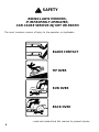
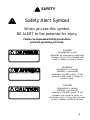
1
OPERATOR’S MANUAL
6000 SERIES
FORWARD MOUNT
ZTR®
2002
IMPORTANT - READ CAREFULLY
The Dixon® ZTR® Mower is both easy and fun to operate.
However, any power mower must be operated properly to be
safe. It is not a toy or a recreational vehicle. Before you
start to use the mower, read the operator’s manual carefully
and become completely familiar with the controls.
The information contained in this manual applies to all
Dixon® ZTR® 6000 Series Commercial Mowers. Your
Dixon dealer will gladly answer any questions.
See your dealer for warranty service, parts and repairs.
INDEX
Page
Safety. . . . . . . . . . . . . . . . . . . . . . . . . . . . . . . . . . . . . 4-11
Warranty Policy. . . . . . . . . . . . . . . . . . . . . . . . . . . . . . .12
Specifications. . . . . . . . . . . . . . . . . . . . . . . . . . . . . . . . .13
Seat Adjustment Instructions. . . . . . . . . . . . . . . . . . . . . . . . .14
Controls. . . . . . . . . . . . . . . . . . . . . . . . . . . . . . . . . .15-17
Operation Instructions. . . . . . . . . . . . . . . . . . . 18-24
Care & Maintenance. . . . . . . . . . . . . . . . . . . . . .25-39
Troubleshooting. . . . . . . . . . . . . . . . . . . . . . . . . . 40-41
Standard Service Parts List. . . . . . . . . . . . . . . . . . . .42
6000 Series Forward Mount
Part No. 13090-0601
3
SAFETY
RIDING LAWN MOWERS,
IF IMPROPERLY OPERATED,
CAN CAUSE SERIOUS INJURY OR DEATH.
The most common causes of injury to the operator or bystander...
BLADE CONTACT
TIP OVER
RUN OVER
BACK OVER
...read and understand this manual to prevent injuries.
4
SAFETY
Safety Alert Symbol
When you see this symbol,
BE ALERT to the potential for injury.
Follow recommended safety precautions
and safe operating practices.
DANGER
(highlighted in red)
indicates an imminently hazardous
situation which, if not avoided, will
result in death or serious injury.
WARNING
(highlighted in orange)
indicates a potentially
hazardous situation which, if not
avoided, could result in death or
serious injury.
CAUTION
(highlighted in yellow)
indicates a potentially
hazardous situation which, if not
avoided, may result in minor or
moderate injury. It may also be used
to alert against unsafe practices.
5
SAFETY
Failure to observe the following safety
instructions could result in serious injury or death.
GENERAL OPERATION:
•Read, understand, and follow all instructions in the manual
and on the mower before starting.
•Only allow responsible adults, who are familiar with the
instructions, to operate the mower.
•Clear the area of objects such as rocks, toys, wire, etc.,
which could be picked up and thrown by the blade.
•Be sure the area is clear of other people before mowing.
Stop mower if anyone enters the area.
•NEVER carry passengers.
•Do not mow in reverse unless absolutely necessary. Always
look down and behind before and while backing.
•Be aware of the mower discharge direction and do not point
it at anyone.
•Do not operate the mower without either the entire grass
catcher or the deflector in place.
•Slow down before turning.
•Never leave a running mower unattended. Always turn off
blades, set parking brake, stop engine and remove key before
dismounting.
6
SAFETY
GENERAL OPERATION (continued):
•Turn off blades when not mowing.
•Stop engine before removing grass catcher or unclogging
chute.
•Mow only in daylight or good artificial light.
•Do not operate the mower while under the influence of
alcohol or drugs.
•Watch for traffic when operating near or crossingroadways.
•Use extra care when loading or unloading the mower into a
trailer or truck. Do not ride the mower when loading and
unloading.
•Always wear safety goggles or safety glasses with side
shields when operating mower.
•Data indicates that operators, age 60 years and above, are
involved in a large percentage of riding mower-related
injuries. These operators should evaluate their ability to
operate the riding mower safely enough to protect
themselves and others from serious injury.
•Follow the manufacturer’s recommendation for wheel
weights and counterweights.
•Maintain or replace safety & instruction labels as needed.
WARNING:
The engine exhaust from this product contains chemicals known to the
State of California to cause cancer, birth defects or other reproductive
harm.
7
SAFETY
SLOPE OPERATION:
Slopes are a major factor related to loss-of-control and tip-over accidents,
which can result in severe injury or death.
All slopes require extra caution.
If you cannot back up the slope or if you feel uneasy on it,
do not mow it!
DO
•
Mow across the slope with your Dixon ZTR - never up or down.
•
Remove obstacles such as rocks, tree limbs, etc.
•
Watch for holes, ruts or bumps. Uneven terrain could overturn the
mower. Tall grass can hide obstacles.
•
Use slow speed. Tires may lose traction on slopes even though the
brakes are functioning properly.
•
Use extra care with grass catchers or other attachments. These can
change the stability of the mower.
•
Keep all movement on the slopes slow and gradual. Do not make
sudden changes in speed or direction.
•
Avoid starting or stopping on a slope. If tires lose traction, disengage
the blades and proceed slowly down the slope.
•
If front wheels lift off the ground, pull the levers back to stabilize the
mower.
DO NOT
•
Do not turn on slopes unless necessary, and then, turn slowly and
gradually downhill, if possible.
•
Do not mow near drop-offs, ditches, or embankments. The mower
could suddenly turn over if a wheel is over the edge of a cliff or ditch,
or if an edge caves in.
•
Do not mow on wet grass. Reduced traction could cause sliding.
•
Do not try to stabilize the mower by putting your foot on the ground.
8
SAFETY
CHILDREN:
Tragic accidents can occur if the operator is
not alert to the presence of children.
Children are attracted to lawn mowers and the mowing activity.
NEVER assume children will stay where they were last seen.
Be alert to avoid accidents.
•
Keep children out of the mowing area and under the
watchful care of another responsible adult.
•
Be alert and turn mower off if a child enters the area.
•
Before and during backing, look BEHIND and DOWN for
small children.
•
Never carry children. They may fall off and be seriously
injured or interfere with safe mower operation.
•
Never allow children to operate the mower.
•
Use extra care when approaching blind corners, shrubs,
trees, or other objects that may obscure vision.
9
SAFETY
SERVICE:
•
Use extra care in handling gasoline and other fuels. They are
flammable and vapors are explosive.
Use only an approved container.
Never remove fuel cap or add fuel with engine running.
Allow engine to cool before refueling.
Do not smoke while refueling.
Never refuel the mower indoors.
Never store the mower or fuel container inside a building
where there is an open flame.
If fuel is spilled on clothing, change clothing immediately.
To prevent fire and explosion caused by static electricity:
Never fill containers inside a vehicle or on a truck
or trailer bed with a plastic liner. Always place
containers on the ground away from your vehicle
before filling.
When practical, remove fuel-powered equipment
from the truck or trailer and refuel it on the
ground. If this is not possible, then refuel such
equipment on a trailer with a portable container,
rather than from a fuel dispenser nozzle.
If a fuel dispenser nozzle must be used, keep the
nozzle in contact with the rim of the fuel tank or
container opening at all times until fueling is
complete. Do not use a nozzle lock-open device.
10
SAFETY
SERVICE (continued):
•
Never run a mower inside a closed area. The exhaust fumes are
toxic.
•
Keep nuts and bolts tight, especially blade attachment bolts, and
keep equipment in good condition.
•
Never tamper with safety devices. Check their proper operation
regularly.
•
Keep mower free of grass, leaves, or other debris buildup. Clean
up oil or fuel spillage. Allow mower to cool before storing.
•
Stop and inspect the equipment if you strike an object. Repair,
if necessary, before restarting.
•
Never make adjustments or repairs with the engine running
unless otherwise specified.
•
Grass catcher components are subject to wear, damage and
deterioration, which could expose moving parts or allow objects
to be thrown. Frequently check components and replace with
original equipment parts, when necessary.
•
Mower blades are sharp and can cut. Wrap the blade(s) or wear
gloves, and use extra caution when servicing them.
•
Batteries contain sulfuric acid. To prevent burns avoid contact
with skin, eyes and clothing. To prevent a fire or explosion keep
sparks and open flames away from battery.
•
Before disconnecting the negative (-) ground cable, make sure all
switches are OFF.
11
DIXON INDUSTRIES, INC.
a BLOUNT company
Airport Industrial Park
P.O. Box 1569
Coffeyville, Ks 67337- 0945
620-251-2000
Fax 620-251-4117
DIXON LIMITED WARRANTY POLICY - COMMERCIAL MODELS
6000 & 7000 Series
WARRANTY: Home Owner Application: This Dixon Warranty term is for a period of two (2)
years from date of purchase. Commercial Application: Dixon mowers used for commercial
application are warranted for one (1) year from the date of purchase or 400 hours whichever
comes first. Commercial use is specified as use other than, or in addition to, mowing at owner’s
primary place of residence.
DIXON ZTR MOWERS ARE WARRANTED AGAINST DEFECTS IN MATERIALS
AND WORKMANSHIP AND PROVIDES FOR REPLACEMENT OR REPAIR OF
PARTS INCLUDING LABOR COSTS. THIS WARRANTY IS SUBJECT TO THE
FOLLOWING CONDITIONS AND LIMITATIONS:
1. Warranty applies only to original retail purchaser of new & unused mowers & accessories.
2. All Dixon warranty must be accomplished by authorized Dixon dealers & in accordance with
Dixon warranty policy & allowances. All warranty claims must be approved by Dixon Industries,
Inc.
3. Battery warranty: Limited to 90 days from date of purchase.
4. Accessories Warranty (Grass Catchers, Snow Blades, Covers, etc.): Limited to 90 days from date of
purchase.
5. Warranty does not apply to damage in transit or incidents of misuse, negligence, accidents, or
alteration. The use of parts or components other than those supplied by Dixon Industries, Inc. VOIDS
ALL WARRANTY.
6. The following items are not covered by this warranty policy:
a.
Pick up and delivery charges for transportation of mower to and from an authorized Dixon
dealer’s place of business.
b.
Routine maintenance or adjustments.
c.
Belts/cutting blades/hydrostatic filters.
d.
Engines - All engines used on Dixon ZTR mowers are warranted by the individual engine
manufacturer.
e.
Any costs or expense of providing substitute equipment while repair work is being
performed on a warranted mower.
7. There is no other express warranty. Implied warranties, including those of merchantability and fitness
for a particular purpose, are limited to the same duration of the express warranty, and to the extent
permitted by law any and all implied warranties are excluded. Liabilities for consequential damages
under any and all warranties are excluded.
Blue/Customer Yellow/Dealer White/Dixon Ind.
WARRANTY VALIDATION: At the time of sale, selling dealer must review each portion of this warranty
document, complete the information section below, secure customer’s signature & send copy to Dixon
Industries, Inc.
DATE OF PURCHASE____________________MODEL___________________S/N_______________
_____________________________________
______________________________________
Owner’s Name
Dealership
_____________________________________
______________________________________
Address
Address
______________________________________
_______________________________________
_____________________________
12
______________________________
SPECIFICATIONS
6000 Series Forward Mount
CHASSIS:
Sheet metal construction frame.
BODY:
Folded sheet metal. Seat lifts up for access to battery and belt service.
SEAT:
Designed for operator comfort by use of high density closed cell foam
padded back and arm rests, upholstered with CorduraTM waterrepellent fabric. Seat is adjustable fore and aft.
MOWER DECK:
Two decks are available. Both are made of 12 GA fabricated welded
construction with 10 GA reinforcement plate. Three blades
combine for either a 48” or 60” cut width. Cut height approximately 1”
to 5” via 9 position lift handle.
BLADE DRIVE:
Electric clutch.
DRIVE SYSTEM:
Each rear wheel is independently driven by a HydroGear BDU-10L Series
70 hydrostatic transmission. The hydrostatic transmissions, in turn,
power a fully enclosed HydroGear gearbox.
ENGINE:
23 HP Kohler Command, 4-cycle, v-configuration, overhead valve, air
cooled, gasoline, horizontal shaft, aluminum head, and crankcase with
cast iron liners, full pressure lubrication/full flow filter, pulse-type fuel
pump, fixed jet carburetor w/smart-choke, electronic ignition, in-line fuel
filter, dual element air cleaner.
STARTING SYSTEM: Electric by key switch operation with safety interlocks on parking brake
and blade drive clutch.
TIRES:
Front 4.10 x 3.50-4
Rear 6.00 x 13.00-5
Drive 10.0 x 10.00-20
RECOMMENDED
TIRE PRESSURE:
Front
Rear
CAPACITIES:
Fuel - 5 gallons
Hydrostat oil tank - 3 quart with in-line 40 micron filter
Hydrostat oil recommendation, refer to page 29
Engine - 2 quarts SAE 10W30 (with filter)
DIMENSIONS:
Width
57-1/2”(48” Deck) 69-1/2” (60” Deck)
Height 45-1/2”
Length 96” (48” Deck), 101” (60” Deck)
Weight 960 lbs. (48” Deck), 1030 lbs. (60” Deck)
16 lbs.
12 lbs.
Additional information provided in service instructions under the individual component.
13
SEAT ADJUSTMENT INSTRUCTIONS
6000 SERIES
14
1.
Grasp seat slide adjuster and move
it into adjustment position.
2.
Slide seat forward or backward.
3.
Release seat slide adjuster.
CONTROLS
CONTROL LEVERS
Note:
For access to the seat, move control levers to neutral position and
swing them outward.
TO GO FORWARD:
•From neutral position, gently push both control levers forward.
•To increase speed, move levers further forward.
TO GO BACKWARD:
•From neutral position, gently pull both control levers toward you.
TURNING:
•Turning is controlled by moving one control lever slightly forward or
rearward of the other.
•To turn left, move left lever rearward of the right lever.
•To turn right, move right lever rearward of the left lever.
•To turn on mower’s own axis (zero turning radius), stop and move one
lever to reverse position and the other to forward position.
BRAKING:
•To brake mower, move both levers in direction opposite of travel.
LEFT TURN OPPOSITE
Note: The pressure required to operate the mower is very light.
15
CONTROLS
PARKING BRAKE
The parking brake is designed to hold the
mower from moving and is not intended
for use in stopping the mower while it is
in motion.
Engage parking brake
CAUTION before starting engine.
TO SET PARKING BRAKE
The hand operated parking brake is located at the right
hand side of the mower.
To engage brake, pull rearward.
To release brake, move lever forward.
NOTE: Always set parking brake before dismounting.
Release parking brake before moving mower.
HYDRO-GEAR DRIVE SYSTEM:
Allows the mower to turn on its own axis (zero turning
radius).
Each lever controls one side of the mower.
16
CONTROLS
MOWER BLADE SWITCH:
Located on the control panel to the operator’s right.
To engage blades: pull up on switch
To disengage blades: push down
CHOKE CONTROL LEVER:
Located on control panel to operator’s left. Use to start a cold engine.
THROTTLE CONTROL LEVER:
Located on control panel to operator’s right. Controls engine speed, slow
to maximum.
While mowing, throttle control should be set to MAXIMUM or
wide open setting to insure adequate cooling of the engine and
to maintain mower deck blade speed.
CIRCUIT BREAKER:
Located on control panel to the operator’s right. Protection of the
electrical system is by (2) 30 amp circuit breakers.
If circuit breaker trips, push button to reset.
If condtion repeats, consult dealer for inspection and repair.
MOWER DECK CUT HEIGHT LIFT LEVER:
Located to the right and front of the operator.
Controls the cutting height.
Nine positions of adjustment.
Depress trigger and move lever forward to lower deck.
Depress trigger and pull lever back to raise deck.
Note:
To achieve a 1” to 3” cutting range, the bar connecting the deck
lift handle and the rear of the deck must be in the first hole. To
achieve a 3” to 5” range, the bar connecting the deck lift handle
and the rear of the deck must be in the second hole.
Note:
Always use high position for transport.
17
OPERATION INSTRUCTIONS
The safe and successful operation of the 6000 Series will depend
upon the operator having the correct knowledge of all controls used
on the mower and making good judgements about the terrain to be
mowed.
NEVER allow anyone to operate the mower without complete
knowledge of all controls and their functions.
During initial operation, “learning to drive”, set throttle at slow speed.
Sound judgement by the operator will prevent accidents.
TOWING
Towing a trailer or other attachment that is too heavy could damge
the drive or cause the mower to become unstable. Limit loads to
500 pounds or less with this mower.
BEFORE OPERATING MOWER:
18
1.
Read and observe all safety instructions on your
mower and in the manual.
2.
Read engine manufacturer’s operating and
mainte nance instructions.
3.
Check engine oil.
4.
Check fuel cap to be sure it is in place.
5.
Be sure parking brake is on.
6.
Be sure that mower blade drive is off.
7.
Know how to stop engine. (Turn key to off position).
OPERATION INSTRUCTIONS
INTERLOCK SWITCH TEST
Note: Operator must be seated in normal operating position to
perform these tests.
1.
With engine off, turn mower blade on and attempt to
start engine.
ENGINE SHOULD NOT START.
2.
With engine off, move control levers in and attempt to
start engine.
ENGINE SHOULD NOT START
3.
In a SAFE AREA, away from bystanders, start the
engine, place throttle setting at maximum or full.
Engage the blade drive through the electric clutch
switch. Raise slightly off of seat.
ENGINE SHOULD STOP.
4.
With engine running, set parking brake and move
levers inboard.
ENGINE SHOULD STOP.
If any safety check fails, do not operate the mower until the
system has been checked and repaired by an authorized
Dixon ZTR dealer.
19
OPERATION INSTRUCTIONS
STARTING INSTRUCTIONS (cold engine):
1.
Operator must be seated in normal operating position.
2.
Set parking brake.
3.
Push choke control lever fully foward.
4.
Push throttle control lever to 1/2 setting.
5.
Insert ignition key and turn to “start” position. When engine
starts, release ignition key. Key will return to “run” position.
6.
Once engine starts to warm up, slowly move choke control lever to
the fully closed position.
7.
Move throttle control lever to the wide open or maximum setting
for actual operation of the mower deck.
8.
Engine must be operated at wide open or maximum setting to
insure adequate lubrication, cooling and cut quality of the mower
deck.
Note:
6000 Series mowers will require a slightly longer warm-up period
using partial choke settings.
CAUTION
20
Do not operate the engine in an enclosed area
due to the harmful exhaust gas produced.
OPERATION INSTRUCTIONS
STARTING INSTRUCTIONS (engine has been operated):
1.
Operator must be seated in normal operating position.
2.
Set parking brake.
3.
Push throttle control lever to 1/4 to 1/2 setting.
5.
Insert ignition key and turn to “start” position. When engine
starts, release ignition key. Key will return to “run” position.
6.
Move throttle control lever to the wide open or maximum setting
for actual operation of the mower deck.
Note:
Model 6023 may require partial choke setting to insure
adequate engagement of the mower deck. As engine
warms, open choke lever.
7.
Engine must be operated at wide open or maximum setting to
insure adequate lubrication, cooling and cut quality of the mower
deck.
Note:
6000 Series mowers will require a slightly longer warm-up period
using partial choke settings.
CAUTION
Do not operate the engine in an enclosed area
due to the harmful exhaust gas produced.
Notes: On initial operation, set throttle at slow speed.
Engine cannot be restarted when blades are engaged.
Safety switches stop engine when operator leaves seat while
mower blades are engaged.
Always turn engine off when leaving mower.
21
OPERATION INSTRUCTIONS
MOWING INSTRUCTIONS:
CAUTION
1.
2.
3.
4.
Start engine and set throttle at full speed.
Set desired cut height.
Release park brake.
Move control levers in and operate per the
control instructions on Page 15.
CAUTION
5.
22
Be sure that deflector is properly
installed on the discharge chute.
Check the area to assure there is no
one near.
Engage mower blades.
OPERATION INSTRUCTIONS
To Free Wheel Machine
(unlock transmission for towing):
The free wheel levers are located on each
side of the mower below the seat mount (flip up
the foot deck to access them). Lift the levers
slightly, push them to the rear and down to
release the transmissions for free wheeling. To
engage the transmissions, lift the levers slightly,
pull them forward and then down.
BEFORE PUSHING OR TOWING TRACTOR,
TRANSMISSION MUST BE UNLOCKED,
AND PARKING BRAKE RELEASED. THE
TRACTOR SHOULD NEVER BE PUSHED
OR PULLED OVER TWO (2) MPH FOR
ANY APPRECIABLE DISTANCE.
23
OPERATION INSTRUCTIONS
GRASS HEIGHT AND CUTTING SUGGESTIONS:
Do not attempt to cut grass when it is wet.
If the grass is tall, place the mower deck cut height lever in the
top or second notch. “Initially” overlap cutting swaths instead
of a full swath with each pass. Some applications may require
a second cutting.
Keep the underside of the mower deck clean.
Maintain sharp blades throughout the cutting season.
As a rule of thumb, never cut off more than 1/3 of the total
grass blade length.
Correct mowing height can reduce weeds and disease by
50% to 80%.
The following grass cut heights are based an adequate
moisture conditions and normal thatch build-up in a healthy
lawn. Some locations and applications may require slightly
different cut heights. If in doubt, consult your local lawn
professional for assistance.
Grass Types
Bermudagrass
Bluegrass
Buffalograss
Ryegrass
Tall Fescue
Zoysiagrass
24
Best Cut Heights
1 - 2”
2 - 3”
11/2 -3”
2 - 3”
3-31/2”
1 - 3”
CARE AND MAINTENANCE
CAUTION
Before performing any maintenance, turn off engine,
allow to cool & remove key.
Use extreme care when working on machinery.
Do not wear watch or jewelry. Do not wear loose fitting clothes,
and observe all common safety practices with tools.
MAINTENANCE SCHEDULE
Check crankcase oil level. . . . . . . . . . . . . . . . . . . . . . . . . . . . . . . .before each use
Clean grass from hydrostat fans and cooling fans. . . . . . . .before each use
Check air intake screen. . . . . . . . . . . . . . . . . . . . . . . . . . . . . . . . . . .after each use
Clean grass under deck. . . . . . . . . . . . . . . . . . . . . . . . . . . . . . . . . . after each use
Check tire pressure. . . . . . . . . . . . . . . . . . . . . . . . . . . . . . . . . . . . . . . every 10 hours
Check mower blades for sharpness. . . . . . . . . . . . . . . . . . . . . . . every 10 hours
Check air filter element. . . . . . . . . . . . . . . . . . . . . . . . . . . . . . . . . . . . every 10 hours
Service air filter element. . . . . . . . . . . . . . . . . . . . . . . . . . . . . . . . . . .every 25 hours
Check hydrostatic transmission fluid. . . . . . . . . . . . . . . . . . . . . . .every 25 hours
Service engine air filter pre-cleaner. . . . . . . . . . . . . . . . . . . . . . . .every 25 hours
Grease driveline (3 fittings). . . . . . . . . . . . . . . . . . . . . . . . . . . . . . . . every 50 hours
Grease jack shaft. . . . . . . . . . . . . . . . . . . . . . . . . . . . . . . . . . . . . . . . . .every 50 hours
Grease deck pivot tube. . . . . . . . . . . . . . . . . . . . . . . . . . . . . . . . . . . . every 50 hours
Check adjustment of P.T.O. clutch. . . . . . . . . . . . . . . . . . . . . . . . . .every 50 hours
(or if blades do not stop within 7 seconds
from switch disengagement)
Check all belts. . . . . . . . . . . . . . . . . . . . . . . . . . . . . . . . . . . . . . . . . . . . every 50 hours
(20 hours break-in)
Replace air filter element. . . . . . . . . . . . . . . . . . . . . . . . . . . . . . . . every 100 hours
Change engine crankcase oil and filter. . . . . . . . . . . . . . . . . . .every 100 hours
(5 hours break-in)
Check spark plugs. . . . . . . . . . . . . . . . . . . . . . . . . . . .annually or every 200 hours
Change oil in deck gearbox. . . . . . . . . . . . . . . . . . .annually or every 500 hours
Change hydrostat oil & oil filter (7252). . . . . . . . . . . . . . . . . . .every 500 hours
(100 hours break-in)
Perform these maintenance procedures more frequently under
extremely dusty , dirty conditions. Replace decals when illegible.
25
CARE AND MAINTENANCE
ENGINE:
For complete maintenance and operating information of the
engine, please refer to the maintenance instructions furnished
by the engine manufacturer and included in your Zero Turn
Radius mower information packet.
Note:
Air intake screen must be kept clean. If plugged, engine
may be seriously damaged by overheating.
BATTERY:
Battery contains sulfuric acid electrolyte which is
CAUTION poisonous and corrosive.
This is a maintenance-free battery and the fluid level cannot
be checked.
Charge battery if required.
OFF SEASON BATTERY STORAGE:
DO NOT remove battery from mower.
Clean top of battery and terminals with baking soda and water.
Identify each cable so they can be reconnected to the correct
terminal.
Disconnect cables from terminals. ALWAYS disconnect ground
cable first and reconnect last.
Charge battery.
TIRES:
Correct tire pressure is essential for efficient operation of the
mower. Check tire pressure periodically. Inflate tires to the
pressure listed below.
Front tires
Rear tires
-
16-20 lbs.
8-14 lbs.
Lug nuts or lug bolts should be checked regularly for tightness.
26
CARE AND MAINTENANCE
CAUTION
Stop engine and remove ignition key for safety.
Wear heavy, thick gloves when holding onto cutter
blade, avoid the sharp edge of the blade.
MOWER BLADES:
Check sharpness of mower blades after every 10 hours of operation.
To sharpen blades, proceed as follows.
1.
Remove bolt and flat washer mounting blade on shaft.
Remove blade.
2.
Blades should be discarded when worn excessively.
3.
Sharpen blade with a hand file, electric grinder or blade
sharpener. Wear gloves and eye protection when
sharpening. Grind blade at original 25 degree bevel.
4.
Check balance of blade by positioning the blade on a nail
or blade balance pedestal. Grind the blade on the end that
is heavier until both sides balance.
5.
Install blade, flat washer & bolt. Make sure to tighten
bolt to 60 ft. lbs.
DANGEROUS!
DO NOT USE
BLADE IN THIS
CONDITION!
New Blade
When notch starts,
discard blade
27
CARE AND MAINTENANCE
BELTS:
The main hydro drive belt should be checked after the
first 10 hours and every 50 hours thereafter. Replace
any belts found to be in poor condition. The deck belt is
equipped with a spring loaded belt tightener and does
not require tightening adjustments. The hydrostatic
transmission belt is adjusted manually (see page 32
for tensioning instructions).
LUBRICATION:
A.
B.
C.
D.
E.
F.
Engine: Follow engine manufacturer’s
recommendation.
Deck spindles: Lubricate with 3 “shots” only,
every 100 hours.
Hydrostatic transmission and filter.
P.T.O. Shaft: Grease every 50 hours.
Deck lift rod weldment: Grease every 50 hours.
Deck Gearbox: See page 31.
SCALPER ROLLER BOLTS:
Scalper roller bolts should be tightened until the spacer
bushing will not run relative to the scalper bracket to
prevent undue wear on the end of the spacer bushing
and the scalper bracket. The proper torque is from 17
to 20 ft. lbs.
28
CARE AND MAINTENANCE
HYDROSTATIC TRANSMISSION:
Before each use, check to be sure that the cooling fins
of the hydrostatic transmission are clean. Excessive
accumulation of oil, dirt, or trash may cause the
transmission to overheat. NEVER WASH ACROSS
TOP OF RESERVOIR with water or steam. Fill reservoir
as required per instructions below.
CHECKING & REPLENISHING OIL IN HYDROSTATIC
TRANSMISSION:
Check the oil level in hydrostatic transmission oil reservoir
after every 25 hours of usage. Do not remove the reservoir
cap to check the oil level as this allows dirt to enter the
transmission. Replenish as needed with SAE 20W-50
motor oil. Any high quality engine oil with an API classification
Hydrostatic
of SG/CD is recommended.
Transmission
Oil Reservoir
A. Wipe area of oil reservoir cap
clean of dirt & debris.
B. Remove oil reservoir cap.
C. Fill to line marked on reservoir.
D. Do not overfill.
E. When checking oil level, be very
careful to keep the reservoir
clean and fill only with clean oil. Hydrostatic Transmisson
Filter
Change the oil in the reservoir
and hydrostat transmission oil filter
after the first 100 hours of use. Then
every 500 hours after that. Remove
the filter and be sure all oil has drained
from the reservoir. Replace with new
Dixon filter P/N 7252 and SAE 20W-50
motor oil.
29
CARE AND MAINTENANCE
PARKING BRAKE ADJUSTMENT
With the brake handle in the release position, remove
the cotter pin from the castle nut. Insert a 0.010
feeler gauge between the brake disc and the brake
puck. Tighten the castle nut with the feeler gauge
inserted until the gauge fits snugly between the disc
and puck. The gap should not be so tight that the feeler
gauge cannot be reinserted after removal. Back the
castle nut to the closest pin hole and reinsert the
cotter pin. Repeat for other side. See picture below.
CASTLE NUT
COTTER PIN
0.10 GAP BETWEEN BRAKE DISC AND
30
CARE AND MAINTENANCE
CHECK DECK DRIVE GEARBOX FLUID LEVEL:
The fluid level only needs to be checked if oily residue is found on the
gearbox housing.
1. Rotate deck into upright position (see deck servicing
procedure).
2. Remove the hex head plug at the low end of the gearbox
housing. (Plug closest to the drive shaft.) The fluid level
should be level with the bottom of the threaded hole.
CHANGING THE FLUID IN DECK DRIVE GEARBOX:
1. Rotate the deck into the upright position & remove drain
plug from bottom of gearbox.
2. Lower deck to drain fluid.
3. When the fluid is drained from gearbox raise deck back up
and reinsert the drain plug.
4. Remove hex head plug from side of gearbox and fill with
automatic transmission fluid (ATF). Fill to bottom of the
hole that the plug is removed from.
5. Reinstall hex head plug.
DRAIN PLUG
HEX HEAD PLUG
GEARBOX
31
CARE AND MAINTENANCE
HYDROSTAT DRIVE BELT TENSION ADJUSTMENT:
In normal use the hydrostat drive belt tension should be checked after
the first 20 hours of use for normal wear and stretch. It may be
adjusted as follows:
1.
2.
Loosen the idler pulley locking nut until the idler pulley
can be just moved relative to the mounting bracket.
Tighten the tension adjust bolt until the belt is tight
enough to prevent belt slippage. Belt should deflect
approximately 3/8” to 5/8” under moderate
pressure. Do not over tighten.
Note: If belt is over-tightened it will often make a “chattering”
noise.
3.
Retighten the slide locking nut.
Motor Pulley
Tension Adjust Bolt
Hydrostatic Drive Belt
Idler Pulley
Hydrostatic Drive Pulley
Cooling Fins
4.
32
Retighten the tension adjust bolt 1/4 turn to set the
lockwasher and prevent loosening of the tension
adjust bolt.
CARE AND MAINTENANCE
STEERING CONTROL ADJUSTMENTS:
To adjust neutral:
1.
2.
3.
4.
Remove fender skirts from each side of the machine.
Block up the unit so drive wheels are off ground.
Start engine and run at fast idle with steering control
levers in “out” position. Brake must be disengaged
and seat switch activated.
Loosen the locknuts tightened against the rod end
ball joints in the upper linkage assembly.
Note: One of these is a left hand nut and will have to be
turned backwards.
5.
6.
7.
8.
Adjust the neutral position by turning the rod in the
upper linkage until the wheel stops turning.
Retighten the nuts on the upper linakge assembly and
check to see that the drive wheel is still not turning.
Repeat steps 1-6 for the other side.
Shut off engine before removing the blocks.
33
CARE AND MAINTENANCE
STEERING CONTROL ADJUSTMENTS (continued):
To adjust “IN” position of the steering controls:
1.
2.
3.
4.
5.
Remove the two front bolts, lockwashers, and
washers which hold the fender cap.
Pull the boot from the hole in the fender cap, exposing
the cast iron lever.
Using a 5/32” Allen wrench, turn the setscrew to
adjust the stop.
Replace the boot into the hole in the fender cap.
Replace the two front bolts, lockwashers and washers.
To align handles:
Sit on the seat and push the control levers full forward and full
backward. If the ends do not match, the handles may be
adjusted as follows:
1.
Locate setscrew stops in the steering control lever
base which stop the lever in each direction.
Note: The one at the rear is the stop for forwad and
the one in the front is the stop for reverse.
2.
34
Adjust setscrew stops so that handles line up
together when shifted full forward and full reverse.
CARE AND MAINTENANCE
STEERING CONTROL ADJUSTMENTS (continued):
Adjusting for Straight Forward Tracking:
In large open area, actuate the control handles into the full
forward position. If mower veers in either direction (left or right)
some adjustment is necessary.
1.
If mower veers to right, right hydrostat needs to be
sped up. If mower veers to left, left hydrostat needs to
be sped up.
Stop machine and shut off engine.
Slightly loosen bolt at lower end of upper linkage
assembly on side that is slower. Using a 1/8” Allen
wrench turn the setscrew 1/4 turn in. It may take
several test drives to get mower to track straight
forward.
Once the tracking is to the operators liking, completely
tighten the bolt on the control linkage assembly that
was loosened earlier.
Recheck to make sure neutral adjust has not been
affected.
2.
3.
4.
5,
Access Hole
Fender
Cap
Rod End
Ball Joint
Forward Stop
Setscrew
Reverse Stop
Setscrew
LH Locknut
Turn this rod to
adjust neutral
Setscrew used to
Adjust Forward
Tracking
Upper Linkage
Assembly
RH Locknut
Loosen Bolt
on Linkage
35
CARE AND MAINTENANCE
TILTING THE DECK (see diagram-page37)
1.
2.
3.
4.
5.
6.
7.
Set the parking brake.
Raise the foot deck into vertical position and lock into
place.
Remove the quick release pin from the anti-buck
cylinder at deck end. Lift the cylinder straight up.
Use left-hand control lever to hold cylinder in up-right
position.
Place the deck lift handle in the lowest cutting position.
Use lift assist bar, located on left-hand side of deck,
inside the deck lift tube.
Raise deck lift handle catch, rock handle back and forth
until quick release pin pulls free with little effort.
Lift up on the front of the deck until deck rotates past
90 degrees. The middle hole on the anti-buck cylinder
holder will be in line with the slot on the foot deck
locking device. Use the quick release pin to secure the
deck in the upright position.
LOWER & REATTACH THE DECK(see diagram-page 37)
1.
2.
3.
4.
5.
36
Rotate the deck back to horizontal position.
Stand on front of deck and align deck lift bar with deck
lift handle, rock handle back and forth until quick release
pin slips through. Note the orientation of the holes in
the bar. The first hole is for low cutting 1" to 3", the
second hole is for high cutting 3" to 5".
Lift the rear corner of the deck until the down hanger
engages the push bar. Repeat for other side.
Reattach the anti-buck cylinder.
Unlatch foot deck locking device and lower the foot deck
back to horizontal position.
CARE AND MAINTENANCE
DOWN HANGER IN
ENGAGED POSITION
FOOT DECK IN
VERTICAL POSITION
FOOT DECK
LOCKING DEVICE
USE THIS HANDLE TO HELP
DISENGAGE DOWN HANGER
ANTI-BUCK
CYLINDER
QUICK RELEASE PIN
(deck lift handle)
QUICK RELEASE
PIN (anti-buck
cylinder)
LIFT CORNER
OF DECK
MIDDLE HOLE
ON ANTI-BUCK
CYLINDER
HOLDER
DECK LIFT HANDLE CATCH
DECK LIFT BAR
DECK LIFT TUBE
(Lift Assist Bar Inside)
37
CARE AND MAINTENANCE
LEVELING THE DECK:
The deck comes from the manufacturer pre-leveled. If the deck does appear to be
cutting unlevel follow this procedure.
1.
Set tire pressure on all of the tires to correct specifications (see
page 26).
2.
Place machine on a level slab of concrete.
3.
Move blades by hand so all the blades are pointed in the same
direction (see diagram on page 39). Measure from the blade tip
(beveled edge) to the ground, all three blades. If there is more
than a 3/16" difference from one side to the other, the deck
should be leveled.
4.
Remove the clevis pin from the rear of the lift spring rod, on the
high side. The lift spring rod is two parts-one threaded into the
other. Turn the lift spring rod counter-clockwise 2 turns.
Reassemble clevis pin and re-measure. Repeat as required to
achieve a difference of no more than 3/16" from one side to the
other.
5,
If the deck is level side to side but high or low at the center blade,
both lift spring rods must be adjusted equal amounts. Shortening
the lift spring rods will bring the center blade up and lengthening
the lift spring rods will let the center blade down.
Lift Spring Rod
Lift Spring
Clevis Pin
Tension Adjust Bolt
38
CARE AND MAINTENANCE
BLADE
DISCHARGE SIDE
DECK SPINDLE BELT DIAGRAM
(TOP VIEW)
39
TROUBLESHOOTING
1.
ENGINE WON’T TURN OVER
Mower blades engaged- - - - - - - - - - - - - - - - - - - - - - -disengage blades
Drive not in neutral - - - - - - - - - - - - - - - - - - move control levers to neutral “OUT”
Breaker trips- - - - - - - - - - - - - - - - - - - - - - - - - - - - - - - - - - - - - - - - - - - - - - - - - - - reset breaker
Dead battery- - - - - - - - - - - - - - - - - - - - - - - - - - - - - - - - charge or replace
Solenoid- - - - - - - - - - - - - - - - - - - - - - - - - - - - - - - - - - - - - - - - -consult dealer
Ignition switch- - - - - - - - - - - - - - - - - - - - - - - - - - - - - - - - - - -consult dealer
Starter- - - - - - - - - - - - - - - - - - - - - - - - - - - - - - - - - - - - - - - - - -consult dealer
Parking brake not on- - - - - - - - - - - - - - - - - - - - -engage parking brake
2.
ENGINE WILL TURN OVER BUT WON’T START
No fuel- - - - - - - - - - - - - - - refuel and/or clean or replace fuel filters
Over or under choked - - - - - - - - - - - - - - - - - - - - - - - - - - - - - - -adjust choke
Spark plug not firing- - - -check spark plug/condition or reset gap*
Carburetor maladjustment- -reset carburetor adjustment/consult dealer
Ignition switch- - - - - - - - - - - - - - consult dealer for carburetor service
3.
HARD TO START ENGINE
Fuel line clogged- - - - - - - - - - - - - clean fuel line and check fuel filter
Faulty fuel pump- - - - - - - - - - - - - - - - - - - - - - - - - - - - - - - - -consult dealer
Over or under choke- - - - - - - - - - - - - - - - - - - - - - - - - - - - - - - - - -adjust choke
Spark plug wire loose or grounded- - - - - - - - -check spark plug wire
Spark plugs faulty /improperly gapped- - - -check plugs/condition/reset gap*
Electronic ignition defective- - - - - - - - - - - - - - - - - - - - - - - - -consult dealer
Dirty or maladjusted carburetor- - - - - - - - readjust */consult dealer for service
4.
ENGINE STARTS BUT CUTS OUT
Water in fuel- - - - - - - - - - - - - - - -drain old fuel-replace with new fuel
Clogged fuel line- - - - - - - - - - - - - - - - - - - - - - - - - - - - - - - -check fuel filter
Fuel tank vent plugged- - - - - - - - - - - - - - - - - - - - - - - - - - - -clean fuel line
Faulty fuel pump- - - - - - - - - - - - - - - - - - - - - - - - - - - - - - - - - - - - check vent
Engine dies when control levers moved “IN”- - - - - - - - - - - - -release parking brake
5.
ENGINE KNOCKS
Low oil level- - - - - - - - - - - - - - - - - - - - - - - - - - - - - - - - - - - - - - - - - - - - check and add oil
Ignition timing off- - - - - - - - - - - - - - - - - - - - - - - - - - - - - - - - - - - - - - - - - -consult dealer
Fuel octane too low- - - - - - - - - - - - - - - - -drain and replace with higher octane fuel
Over heated engine- - - - - - - - - - - - - - - - - - - - - - - - - - - - - - - - shut off and allow to cool
6.
ENGINE IDLES POORLY
Carburetor maladjustment- - - - - - - - - - - - - - - - - - - - - - - - - - - - - - - - - - - - - consult dealer
Improper spark plug gap- - - - - - - - - - - - - - - - - - - - - - - - - - - - - -check and re-gap plug*
Choke stuck on- - - - - - - - - - - - - - - - - - - - - - - - - - - - - - - - - - - - - - - - - - - - - - check or adjust
*See engine manual for adjustments
40
TROUBLESHOOTING
7.
ENGINE SOMETIMES SKIPS AT HIGHER SPEED
Incorrect ignition timing- - - - - - - - - - - - - - - - - - - - - - - - - - - - - - - - - - - - - - - - consult dealer
Carburetor maladjusted- - - - - - - - - - - - - - - - - - - - - - - - - - - - - - - - - -readjust carburetor
Faulty spark plugs- - - - - - - - - - - - - - check spark plug or condition and reset gap*
Bouncing off seat safety switch- - - - - - - - - - - - - - - - - - - -slow down on rough terrain
8.
ENGINE OVERHEATED
Air intake screen or fins clogged- - - - - - - - - - - - - - - - - clean intake screen and fins
Fuel mixture too lean- - - - - - - - - - - - - - - - - - - - - - - - - - - - - - - - - - - - - - - - - - consult dealer
Oil level too low or too high- - - - - - - - - - - - - - - - - - - - - - - - - - - adjust oil level
Improper ignition timing- - - - - - - - - - - - - - - - - - - - - - - - - - - - - - - - - - - - - - -consult dealer
Running engine too slow- - - - - - - - - - - - - - - - - - - - - - - - - -run engine faster
NOTE: Always mow at full throttle setting!
ENGINE BACKFIRES
Carburetor maladjustment- - - - - - - - - - - - - - - - - - - - - - - - - - - - - - - - - - - - -consult dealer
9.
10.
ENGINE RUNS BUT MOWER WON’T MOVE FORWARD
Free wheel levers engaged- - - - - - - - - - - - - - - - - - - - - - - - - - - - - - - - - - - -release levers
Drive belt broken or slipping- - - - - - - - - - - - - - - - - - - - - - -replace drive belt
Shift linkage cable disconnected- - - - - - - - - - - - - - - - - - - - - - - - -reconnect
Transmission shift arm disconnected- - - - - - - - - - - - - - - - - - - -reconnect
Transmission oil low- - - - - - - - - - - - - - - - - - - - - - - - - - - - - - - - - -- - - -add oil
Transmission locks in free wheel position- put in lock position(see pg.23)
Hydrostat oil filter plugged- - - - - - - - - - - - - - - - - - - - - - - - - - - - replace filter
Bad transmission- - - - - - - - - - - - - - - - - - - - - - - - - - - - - - - - - - consult dealer
Gear mating transmission/gearbox disconnected- - - - - - -consult dealer
Air in transmission- - - - - - - - - - - - - - - - - - - - - - - - - - - - - - - - - - - - - - - - - - - - - - bleed air
Not enough tension on drive belt- - - - - - - - - - - - - - - - - - - - - - - - - - - - - - - - -check belt
11.
MOWER LOSES POWER OR TRANSMISSION OVERHEATS
Hydrostat transmission oil too low or high- - -add oil or drain as needed
Transmission damage- - - - - - - - - - - - - - - - - - - - - - - - - - - - - --consult dealer
Transmission blowing oil out cap- - - - overfilled or water contaminated
12.
ENGINE STALLS WHEN BLADES ARE ENGAGED
Operator not on seat- - - - - - - - - - - - - - - - - - - - - - - - - - - - - - - - - - - - - - - - - - - -sit on seat
Faulty interlock system- - - - - - - - - - - - - - - - - - - - - - - - - - - - - - - - - - - - - - - - -consult dealer
Bad blade spindle bearing- - - - - - - - - - - - - - - - - - - - - - - - - - - - - - - - - - - - - consult dealer
Deck drive belt not properly routed- - - - - - - - - - - - - - - - - - - - - - - - - - - - - - - - - - - - reroute
Blades blocked by foreign material- - - - - - - - - - - - - - - - - - - - - - - - - -clean under deck
*See engine manual for engine adjustments
41
STANDARD SERVICE PARTS LIST
MODEL ZTR 6023:
Blades:
Blades:
Lo-Lift P/N 60293 (standard)
Hi-Lift P/N 60295
Serpentine Belt:
Engine to Hydros:
Clutch to Driveshaft:
P/N
P/N
P/N
P/N
Hydrostatic
Transmission Filter:
P/N 7252
60194 (48”)
61086 (60”)
61101
60187
KOHLER AIR AND OIL FILTER PART NUMBERS:
Refer to engine manufacturers manual for recommendations regarding
frequency of service required for engine oil changes and air filter
maintenance.
Protect your engine investment, use only original equipment filters.
MODEL ZTR 6023 (23 HP):
Air Filter & Pre-Cleaner Kit
Engine Oil Filter
78003
78006
IMPORTANT:
Some applications, extreme dirt conditons, or the use of a grass
catcher may require that the engine used on the Model 6023 be
fitted with an OPTIONAL Kohler fresh air filter system. Consult your
dealer or a Kohler engine service center for the part numbers
required to adpat these components to the engine or for additional
information.
42
OWNER
INFORMATION
DIXON INDUSTRIES, INC.
a BLOUNT International Inc. Co.
P.O. Box 1569
Coffeyville, Ks 67337-0945
620-251-2000
FAX 620-251-4117
Date Purchased _________________________________
Mower Model Number ____________________________
Mower Serial Number ____________________________
Purchased From ________________________________
Name
________________________________
Address
________________________________
DATE OIL CHANGED:
___________________
___________________
___________________
___________________
___________________
___________________
___________________
___________________
___________________
___________________
___________________
DATE ENGINE TUNED:
___________________
___________________
___________________
___________________
___________________
___________________
___________________
___________________
___________________
___________________
___________________
43
ZTR®Mowers
WARNING:
The engine exhaust from this product contains chemicals known
to the State of California to cause cancer, birth defects or other
reproductive harm.
Dixon® and ZTR® are registered trademarks of Dixon Industries, Inc.
DIXON INDUSTRIES, INC.
a BLOUNT International Inc. Co.
P.O. Box 1569
Coffeyville, Ks 67337-0945
620-251-2000
6000 Series
Model 6023
Part No. 13090-0601