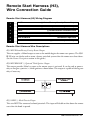
1
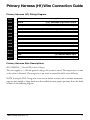
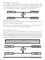
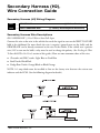
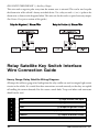
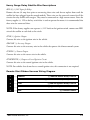
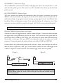
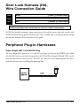
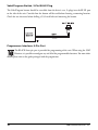
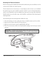
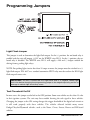
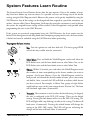
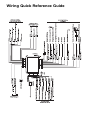
480XP
Installation Guide
NOTE: This product is intended for installation by a professional installer only!
Any attempt to install this product by any person other than a trained professional
may result in severe damage to a vehicle’s electrical system and components.
© 2002 Directed Electronics, Inc. Vista, CA
N552P 4-02
The Bitwriter® (p/n 998T)
requires chip version 1.4 or
newer to program this unit.
Bitwriter™, Code Hopping™, DEI®, Doubleguard®, ESP™, FailSafe®, Ghost Switch™, Learn
Routine™, Nite-Lite®, Nuisance Prevention® Circuitry, NPC®, Revenger®, Silent Mode™,
Soft Chirp®, Stinger®, Valet®, Vehicle Recovery System®, VRS®, and Warn Away® are all
Trademarks or Registered Trademarks of Directed Electronics, Inc.
www.directechs.com
DirectFax 800-9999-11329 Technical Support 800-7753-00800
These resources are for authorized Directed Dealer use only.
Table of Contents
Warning! Safety First ................................4
Installation Points to Remember ...............5
Before Beginning the Installation ..........5
Finding the Tachometer Wire ...............5
Finding the WAIT-TO-START Bulb
Wire for Diesels ....................................6
After the Installation .............................6
Vehicle Anti-Theft Systems
(Immobilizers) ......................................6
Primary Harness (H1)
Wire Connection Guide ...........................7
Primary Harness (H1) Wiring Diagram 7
Primary Harness Wire Descriptions ......7
Secondary Harness (H2),
Wire Connection Guide .........................11
Secondary Harness (H2)
Wiring Diagram .................................11
Secondary Harness Wire Descriptions 11
Relay Satellite Key Switch Interface
Wire Connection Guide .........................12
Heavy Gauge Relay Satellite
Wiring Diagram .................................12
Heavy Gauge Relay Satellite
Wire Descriptions ...............................13
Remote Start Ribbon Harness
Wiring Diagram .................................13
Remote Start Harness (H3),
Wire Connection Guide .........................14
Remote Start Harness (H3)
Wiring Diagram .................................14
Remote Start Harness
Wire Descriptions ...............................14
©
2002 Directed Electronics, Inc.
Neutral Safety Switch Interface ...............16
Testing the Neutral Safety Switch .......16
Door Lock Harness (H4),
Wire Connection Guide .........................17
Peripheral Plug-IIn Harnesses ..................17
Super Bright LED,
2-Pin WHITE Plug ............................17
Valet/Program Switch,
2-Pin BLUE Plug ................................18
Programmer Interface, 3-Pin Port .......18
Mounting the Receiver/Antenna .........19
Programming Jumpers ............................20
Light Flash Jumper .............................20
Tach Threshold On/Off ......................20
System Features Learn Routine ...............21
System Features Menus ...........................23
Menu #1 - Basic Features ....................23
Menu #2 - Remote Start Features .......23
Feature Descriptions ...............................24
Menu #1 - Basic Features ....................24
Menu #2 - Remote Start Features .......25
Transmitter/Receiver Learn Routine .......27
Transmitter Configurations ....................29
Standard Configuration ......................29
Single Button Arm/Disarm
Configuration .....................................29
Tach Learning ........................................30
Shutdown Diagnostics ............................30
Rapid Resume Logic ...............................31
Timer Mode ...........................................31
Safety Check ...........................................32
Troubleshooting .....................................33
Wiring Quick Reference Guide ...............36
3
Warning! Safety First
Due to the complexity of this system, installation of this product must only be performed by an
authorized Directed dealer.
➤ When properly installed, this system can start the vehicle via a command signal from the remote
control transmitter. Therefore, never operate the system in an area that does not have adequate
ventilation. The following precautions are the sole responsibility of the user; however, authorized
Directed dealers should make the following recommendations to all users of this system:
1. Never operate the system in an enclosed or partially enclosed area without ventilation.
2. When parking in an enclosed or partially enclosed area or when having the vehicle serviced,
the remote start system must be disabled using the installed toggle switch.
3. It is the user's sole responsibility to properly handle and keep out of reach from children all
remote control transmitters to assure that the system does not unintentionally remote start.
4. THE USER MUST INSTALL A CARBON MONOXIDE DETECTOR IN OR
➤
ABOUT THE LIVING AREA ADJACENT TO THE VEHICLE. ALL DOORS
LEADING FROM ADJACENT LIVING AREAS TO THE ENCLOSED OR
PARTIALLY ENCLOSED VEHICLE STORAGE AREA MUST AT ALL TIMES
REMAIN CLOSED.
➤
➤
Use of this product in a manner contrary to its intended mode of operation may result in
property damage, personal injury, or death. Except when performing the Safety Check outlined
in this installation guide, (1) Never remotely start the vehicle with the vehicle in gear, and (2)
Never remotely start the vehicle with the keys in the ignition. The user will be responsible for
having the neutral safety feature of the vehicle periodically checked, wherein the vehicle must
not remotely start while the car is in gear. This testing should be performed by an authorized
Directed dealer in accordance with the Safety Check outlined in this product installation guide.
If the vehicle starts in gear, cease remote start operation immediately and consult with the user
to fix the problem immediately.
After the remote start module has been installed, test the remote start module in accordance with
the Safety Check outlined in this installation guide. If the vehicle starts when performing the
Neutral Safety Shutdown Circuit test, the remote start unit has not been properly installed. The
remote start module must be removed or properly reinstalled so that the vehicle does not start in
gear. All installations must be performed by an authorized DEI dealer. OPERATION OF THE
REMOTE START MODULE IF THE VEHICLE STARTS IN GEAR IS
CONTRARY TO ITS INTENDED MODE OF OPERATION. OPERATING THE
REMOTE START SYSTEM UNDER THESE CONDITIONS MAY RESULT IN
PROPERTY DAMAGE OR PERSONAL INJURY. IMMEDIATELY CEASE THE
USE OF THE UNIT AND REPAIR OR DISCONNECT THE INSTALLED
REMOTE START MODULE. DIRECTED WILL NOT BE HELD RESPONSIBLE
OR PAY FOR INSTALLATION OR REINSTALLATION COSTS.
4
©
2002 Directed Electronics, Inc.
Installation Points to Remember
Before Beginning the Installation
IMPORTANT! This product is designed for fuel-injected, automatic transmission
vehicles only. Installing it in a standard transmission vehicle is dangerous and is
contrary to its intended use.
➤
➤
➤
➤
➤
Please read this entire installation guide before beginning the installation. The installation of this
remote start system requires interfacing with many of the vehicle’s systems. Many new vehicles
use low-voltage or multiplexed systems that can be damaged by low-resistance testing devices,
such as test lights and logic probes (computer safe test lights). Test all circuits with a high-quality
digital multi-meter before making connections.
Do not disconnect the battery if the vehicle has an anti-theft-coded radio. If equipped with an
air bag, avoid disconnecting the battery if possible. Many airbag systems will display a diagnostic
code through their warning lights after they lose power. Disconnecting the battery requires this
code to be erased, which can require a trip to the dealer.
Check with the customer on status LED location.
Remove the domelight fuse. This prevents accidentally draining the battery.
Roll down a window to avoid being locked out of the car.
Finding the Tachometer Wire
To test for a tachometer wire, a multimeter capable of testing AC voltage must be used. The
tachometer wire will show between 1V and 6V AC. In multi-coil ignition systems, the system can
learn individual coil wires. Individual coil wires in a multi-coil ignition system will register lower
amounts of AC voltage. Also, if necessary, the system can use a fuel injector control wire for engine
speed sensing.
Common locations for a tachometer wire are the ignition coil, instrument cluster, fuel injectors, or
engine computers.
IMPORTANT! Do not test tachometer wires using a test light or logic probe! This will
damage the vehicle.
©
2002 Directed Electronics, Inc.
5
How to find a tachometer wire with your multimeter:
1. Set to ACV or AC voltage (12V or 20V is fine).
2. Attach the (-) probe of the meter to chassis ground.
3. Start and run the vehicle.
4. Probe the wire you suspect of being the tachometer wire with the red probe of the meter.
5. If this is the correct wire the meter will read between 1V and 6V.
Finding the WAIT-TO-START Bulb Wire for Diesels
In diesel vehicles it is necessary to interface with the wire that turns on the WAIT TO START light
in the dashboard. This wire illuminates the bulb until the vehicle’s glow plugs are properly heated.
When the light goes out the vehicle can be started. This wire is always available at the connector
leading to the bulb in the dashboard. It can also be found at the Engine Control Module (ECM)
in many vehicles.
To test and determine the polarity of this wire:
1. Set your multimeter to DCV or DC voltage (12 or 20V is fine).
2. Attach the (+) probe of the meter to (+)12V.
3. Probe the wire that you suspect leads to the bulb with the (-) probe of the meter.
4. Turn the ignition switch to the ON position.
5. If the meter indicates 12 volts until the light goes out you have isolated the correct wire and the
wire's polarity is negative (ground while the bulb is on).
6. If the meter reads zero volts until the light goes out and then reads 12 volts, you have isolated
the correct wire and the wire's polarity is positive.
After the Installation
➤
➤
Test all functions. The Using Your System section of the Owner's Guide is very helpful when
testing.
Review and complete the Safety Check section of this guide prior to the vehicle reassembly.
Vehicle Anti-Theft Systems (Immobilizers)
Vehicle anti-theft systems (immobilizers) require a bypass module. The bypass module allows for
easy interfacing, while still maintaining the OEM security system’s integrity. For vehicle listings and
required bypass, see DirectFax Document 1059, available only to authorized dealers though the
technical resources listed at the front of this guide.
6
©
2002 Directed Electronics, Inc.
Primary Harness (H1) Wire Connection Guide
Primary Harness (H1) Wiring Diagram
H1/1
___ ORANGE
H1/2
___ WHITE
H1/3
___ WHITE/BLUE
H1/4
___ BLACK/WHITE
H1/5
___ GREEN
No Function
H1/6
___ BLUE
No Function
H1/7
___ VIOLET
No Function
H1/8
___ BLACK
(-) Chassis Ground Input
H1/9
___ OPEN
H1/10
___ BROWN
H1/11
___ RED
H1/12
___ RED/WHITE
(-) 500 mA Armed Output
(+)/(-) Selectable Light Flash Output
(-) Remote Start Activation Input
(-) 200 mA Domelight Supervision Output
No Wire
(-) Horn Honk Output
(+) Constant Power Input
(-) 200 mA Channel 2 Programmable Output
Primary Harness Wire Descriptions
H1/1 ORANGE (-) Ground-When-Armed Output
This wire supplies a (-) 500 mA ground as long as the system is armed. This output ceases as soon
as the system is disarmed. The orange wire is pre-wired to control the 8618 starter kill relay.
NOTE: if using the H1/1 Orange wire to activate an add-on accessory such as window automation,
pager or voice module a 1Amp diode must be installed to ensure proper operation. Insert the diode
as shown in the following diagram.
©
2002 Directed Electronics, Inc.
7
IMPORTANT! Never interrupt any wire other than the starter wire.
H1/2 WHITE (+/-) Selectable Light Flash Output
As shipped, this wire should be connected to the (+) parking light wire. If the light flash polarity
jumper is moved to the (-) position (see the Programming Jumper section of this guide), this wire
supplies a (-) 200 mA output. This is available for driving (-) light control wires in Toyota, Lexus,
BMW, some Mitsubishi, some Mazda, and other models.
NOTE: For parking light systems that draw 10 amps or more, the jumper must be switched to a
(-) light flash output. (See the Programming Jumpers section of this guide.) P/N 8617 or a standard
automotive SPDT relay must be used on the H1/2 light flash output wire.
IMPORTANT! DO NOT connect this wire to a negative vehicle light flash wire before
changing the programming jumper to the negative polarity position or damage to
vehicle light circuit may occur.
8
©
2002 Directed Electronics, Inc.
H1/3 WHITE/BLUE Activation Input
A momentary input on this wire will start or stop the motor, just as transmitting Channel 3 from
the remote transmitter does. It is often connected to an optional momentary push-button switch to
make activating Valet Take Over more convenient.
H1/4 BLACK/WHITE (-) 200 mA Domelight Supervision Output
Connect this wire to the optional domelight supervision relay as shown in the following diagram:
IMPORTANT! This output is only intended to drive a relay. It cannot be connected
directly to the domelight circuit, as the output cannot support the current draw of one
or more bulbs.
H1/8 BLACK (-) Chassis Ground Connection
Connect this wire to a clean, paint-free sheet metal location (driver kick panel) using a factory bolt
that DOES NOT have any vehicle component grounds attached to it. A screw should only be used
when in conjunction with a two-sided lock washer. Under dash brackets and door sheet metal are
not acceptable ground points. It is recommended that all security components be grounded at the
same location.
©
2002 Directed Electronics, Inc.
9
H1/10 BROWN (+) Horn Honk Output
This wire supplies a (-) 200 mA output that can be used to honk the vehicle horn. It outputs a single
pulse when locking the doors with the remote, and two pulses when unlocking with the remote. This
wire will also output pulses for 30 seconds when the Panic Mode is activated. If the vehicle has a (+)
horn circuit, an optional relay can be used to interface with the system, as shown below.
H1/11 RED (+)12V constant power input
Before connecting this wire, remove the supplied fuse. Connect to the battery positive terminal or
the constant 12V supply to the ignition switch.
NOTE: Always use a fuse within 12 inches of the point you obtain (+)12V. Do not use the 15A
fuse in the harness for this purpose. This fuse protects the module itself.
H1/12 RED/WHITE (-) 200 mA output
When the system receives the code controlling Channel 2, for longer than 1.5 seconds, the
RED/WHITE wire will supply an output as long as the transmission continues. This is often used
to operate a trunk/hatch release or other relay-driven function. This output can also be programmed
to provide the following types of output: Instant validity, latched, latched-reset with ignition, 30second timed, or second unlock output. (See Features Description section of this guide for details.)
IMPORTANT! Never use this wire to drive anything but a relay or a low-current input!
The transistorized output can only supply 200 mA of current. Connecting directly to a
solenoid, motor, or other high-current device will cause it to fail.
10
©
2002 Directed Electronics, Inc.
Secondary Harness (H2),
Wire Connection Guide
Secondary Harness (H2) Wiring Diagram
H2/1
___ GRAY/BLACK
H2/2
___ LIGHT GREEN/BLACK
(-) Wait-to-Start Input
(-) Factory Disarm/Special Accessory
Secondary Harness Wire Descriptions
H2/1 GRAY/BLACK (-) Diesel Wait-to-Start Bulb Input
Connect this wire to the wire in the vehicle that sends the signal to turn on the WAIT-TO-START
bulb in the dashboard. In most diesels the wire is negative (ground turns on the bulb) and the
GRAY/BLACK can be directly connected to the wire in the vehicle. If the vehicle uses a positive
wire (12V to turn on the bulb) a relay must be used to change the polarity. (See Finding the WaitTo-Start Bulb Wire For Diesels section of this guide.) Here are some common colors of this wire:
➤
➤
➤
Chevrolet and GMC trucks: Light Blue or Dark Blue
Ford Trucks: Black/Pink
Dodge Ram Trucks: Orange/Black or Black/Orange
NOTE: A 1-amp diode must be installed in line on the factory wire between the wait-to-start
indicator and the ECM. (See the following diagram for details.)
©
2002 Directed Electronics, Inc.
11
H2/2 LIGHT GREEN/BLACK (-) Auxiliary Output
This wire sends a negative pulse every time the remote start is activated. This can be used to pulse
the disarm wire of the vehicle's factory anti-theft device. Use a relay to send a (-) or (+) pulse to the
disarm wire as shown in the diagrams below. This wire can also be used as a special accessory output.
(See Feature Descriptions section of this guide.)
Relay for Negative (-)) Disarm Wire
Relay for Positive (+) Disarm Wire
Relay Satellite Key Switch Interface
Wire Connection Guide
Heavy Gauge Relay Satellite Wiring Diagram
All except the red heavy gauge wires leading from the relay satellite are used to energize high current
circuits in the vehicle. It is crucial that these connections are made correctly so that they are capable
of handling the current demands. For this reason, scotch locks, T-taps and other such connectors
should not be used.
12
1
___ RED
(+) High Current 12V Input
2
___ RED
(+) High Current 12V Input
3
___ PINK
(+) Output to Ignition Circuit
4
___ ORANGE
5
___ PURPLE
6
___ PINK/WHITE
(+) Output to Accessory Circuit
(+) Output to Starter Circuit
(+) Output to Second Ignition Circuit
©
2002 Directed Electronics, Inc.
Heavy Gauge Relay Satellite Wire Descriptions
RED (2) (+)12V Input for Relays
Remove the two 30 amp fuses prior to connecting these wires and do not replace them until the
satellite has been plugged into the control module. These wires are the source of current for all the
circuits the relay satellite will energize. They must be connected to a high current source. Since the
factory supplies (+) 12V to the key switch that is used to operate the motor, it is recommended that
these wires be connected there.
NOTE: If the factory supplies two separate (+) 12V feeds to the ignition switch, connect one RED
wire of the satellite to each feed at the switch.
PINK (+) Ignition Output
Connect this wire to the ignition wire in the vehicle.
ORANGE (+) Accessory Output
Connect this wire to the accessory wire in the vehicle that powers the climate control system.
PURPLE (+) Starter Output
Connect this wire to the starter wire in the vehicle.
PINK/WHITE (+) Output to Second Ignition Circuit
Connect this wire to the second ignition wire in the vehicle.
NOTE: For vehicles that do not have a second ignition wire, this connection is not required.
Remote Start Ribbon Harness Wiring Diagram
©
1
___ PURPLE
2
___ ORANGE
3
___ PINK
(-) 200 mA Ignition Relay Turn-On
4
___ YELLOW
(+) Ignition Input to Remote Start
5
___ RED
2002 Directed Electronics, Inc.
(-) 200 mA Starter Relay Turn-On
(-) 200 mA Accessory Relay Turn-On
(+) Constant Power
13
Remote Start Harness (H3),
Wire Connection Guide
Remote Start Harness (H3) Wiring Diagram
1
___ BLUE
(-) Status/Factory Security Rearm Output
2
___ BLUE/BLACK
(-) 200 mA Optional Third Ignition Output
3
___ GRAY
4
___ BROWN
5
___ VIOLET/WHITE
Tachometer Input Wire
6
___ BLACK/WHITE
(-) Neutral Safety Switch Input
(-) Hood Pinswitch Shutdown Wire
(-) Brake Switch Shutdown Wire
Remote Start Harness Wire Descriptions
H3/1 BLUE Status/Factory Security Rearm Output
This wire supplies a 200mA output as soon as the module begins the remote start process. The H3/1
BLUE wire can also be used to rearm a factory anti-theft system when the remote start shuts down.
(See the Feature Descriptions section in this guide.)
H3/2 BLUE/BLACK (-) Optional Third Ignition Output
This output provides 200mA as soon as the remote starter is activated. It can be used to power a
relay to energize a positive (+) third ignition as shown below. This output is capable of driving two
relays if necessary.
H3/3 GRAY (-) Hood Pinswitch Input
This wire MUST be connected to hood pinswitch. This input will disable or shut down the remote
start when the hood is opened.
14
©
2002 Directed Electronics, Inc.
H3/4 BROWN (+) Brake Switch Input
This wire MUST be connected to the vehicle's brake light wire. This is the wire that shows (+) 12V
when the brake pedal is pressed. The remote start will be disabled or shut down any time the brake
pedal is pressed.
H3/5 VIOLET/WHITE Tachometer Input
This input provides the module with information about the engine's revolutions per minute
(RPMs). It can be connected to the negative side of the coil in vehicles with conventional coils. In
multi-coil and high energy ignition systems locating a proper signal may be more difficult. (See
Installation Points to Remember section of this guide for finding the tachometer wire.) Once
connected, you must teach the system the tach signal. (See Tach Learning section of this guide.)
IMPORTANT! DO NOT use T-Taps or scotch locks for this connection.
H3/6 BLACK/WHITE Neutral Safety Switch Input
Connect this wire to the toggle (override) switch as shown in Figure A. Connect the other wire from
the toggle switch to the park/neutral switch in the vehicle. This wire will test with ground with the
gear selector either in PARK or NEUTRAL. This will prevent the vehicle from accidentally being
started while in a drive gear. This input MUST rest at ground in order for the remote start system
to operate. Connected properly the vehicle will only start while in PARK or NEUTRAL.
In some vehicles, the park/neutral position switch activates a factory starter lock out that will not
allow the starter to operate in a drive gear. In these vehicles, connect this wire to the toggle switch
as shown in Figure B. Connect the other wire from the toggle switch to chassis ground.
Figure A
Figure B
IMPORTANT! Always perform the Vehicle Safety Check section of this guide to verify
that the vehicle cannot be started in ANY drive gear and that the override switch is
functioning properly.
©
2002 Directed Electronics, Inc.
15
Neutral Safety Switch Interface
Some vehicles combine the column shift mechanism and the mechanical neutral safety switch into
one mechanical part. In these vehicles, it is impossible to interface the remote start system before
the neutral safety switch. With this type of vehicle, if the vehicle is left in a drive gear and the remote
start system is activated, the vehicle will move and may cause damage to persons or property. The
following test must be performed before the vehicle is released to the customer.
NOTE: You must complete the remote start system installation before doing the following test.
Ensure that the remote start system is functioning normally. This includes connecting to the brake
as a shut-down.
Testing the Neutral Safety Switch
1. Make sure there is adequate clearance to the front and rear of the vehicle because it may move
slightly.
2. Make sure the hood is closed and there are no remote start shut-downs active.
3. Set the emergency brake.
4. Turn the key to the "run" position, this will release the shifter.
5. Place the car in drive (D).
6. Place your foot directly over the brake pedal, but do not depress it. Be ready to step on the brake
if the starter engages.
7. Activate the remote start system.
8. If the starter engages, immediately depress the brake to shut the remote start system down. If
the starter does not engage, no additional safety system is required.
If the starter engages while testing, refer to technical document #1008 (Neutral Safety Update). It
is available to authorized dealers only from the technical resources listed at the beginning of this
manual.
IMPORTANT! Once the interface is complete, attempt to remote start the vehicle with
the door closed and the key in the ignition. The vehicle should not start. If it does,
recheck the connections.
16
©
2002 Directed Electronics, Inc.
Door Lock Harness (H4),
Wire Connection Guide
H2/A
___ Green
(-) Lock, (+) Unlock Output
H2/B
___ Empty
Unless Using 451M
H2/C
___ Blue
(-) Unlock, (+) Lock Output
IMPORTANT! The door lock outputs are low current and should not be attached
directly to any high current device; they are only to be used to activate relays
NOTE: For detailed instructions about connecting to the vehicle’s power door lock systems, refer
to the Door Lock Wiring guide (Document No. 1041) available only to authorized dealers though
the technical resources listed at the front of this guide.
Peripheral Plug-In Harnesses
Super Bright LED, 2-Pin WHITE Plug
The super bright LED operates at (+) 2 volt DC and plugs into the two-pin WHITE port. Make
sure the LED wires are not shorted to ground as the LED will be damaged. Multiple LED’s can be
used, but they must be wired in series. The LED fits into a 9/32-inch mounting hole. Be sure to
check for clearance prior to drilling the mounting hole.
DIA-41
©
2002 Directed Electronics, Inc.
17
Valet/Program Switch, 2-Pin BLUE Plug
The Valet/Program button should be accessible from the driver’s seat. It plugs into the BLUE port
on the side of the unit. Consider how the button will be used before choosing a mounting location.
Check for rear clearance before drilling a 9/32-inch hole and mounting the button.
Programmer Interface, 3-Pin Port
The BLACK three-pin port is provided for programming of the unit. When using the 998T
Bitwriter, it is possible to configure any and all of the programmable functions. For more information please refer to the guide packaged with the programmer.
18
©
2002 Directed Electronics, Inc.
Mounting the Receiver/Antenna
Receiver/antenna position should be discussed with the vehicle owner prior to installation, since the
antenna may be visible to the vehicle’s operator.
The best location for the receiver/antenna is centered high on either the front or rear windshield.
For optimal range, the antenna should be mounted vertically. It can be mounted horizontally in
relation to the windshield or under the dashboard away from metal, but range will be diminished.
Metallic window tint can also affect range, so this should be a consideration when determining the
mounting location.
After determining the best mounting location, follow these steps:
1. Clean the mounting area with a quality glass cleaner or alcohol to remove any dirt or residue.
2. Plug the receiver/antenna cable into the receiver/antenna.
3. Mount the receiver/antenna using the supplied double-sided tape.
4. Route the receiver/antenna cable to the control module and plug it into the four-pin antenna
connector.
IMPORTANT! To achieve the best possible range, DO NOT leave the antenna cable
bundled under the dash. Always extend the cable full length during installation,
regardless of the antenna mounting location.
©
2002 Directed Electronics, Inc.
19
Programming Jumpers
Light Flash Jumper
This jumper is used to determine the light flash output. In the (+) position, the on-board relay is
enabled and the unit will output (+)12V on the WHITE wire, H1/2. In the (-) position, the onboard relay is disabled. The WHITE wire, H1/2, will supply a 200 mA (-) output suitable for
driving factory parking light relays.
NOTE: For parking light circuits that draw 10 amps or more, the jumper must be switched to a (-)
light flash output. P/N 8617 or a standard automotive SPDT relay must be used on the H1/2 light
flash output harness wire.
IMPORTANT! DO NOT connect the H1/2 light flash wire to a negative vehicle light
flash wire before changing the programming jumper to the negative polarity position or
damage to vehicle light circuit may occur.
Tach Threshold On/Off
In most cases, this jumper can be left in the OFF position. Some new vehicles use less than 12 volts
in their ignition systems. The unit may have trouble learning the tach signal in these vehicles.
Changing the jumper to the ON setting changes the trigger threshold of the digital tach circuit so
it will work properly with these vehicles. The vehicles affected include many newer
Dodge/Chrysler/Plymouth vehicles, such as the Neon, Cirrus, Stratus, Breeze and LH-based
vehicles.
20
©
2002 Directed Electronics, Inc.
System Features Learn Routine
The System Features Learn Routine dictates how the unit operates. Due to the number of steps,
they have been broken up into two menus. It is possible to access and change any of the feature
settings using the Valet/Program switch. However, this process can be greatly simplified by using the
998T Bitwriter. Any of the settings can be changed and then assigned to a particular transmitter, up
to four, a feature called Owner Recognition. Each time that particular transmitter is used to disarm
the system, the assigned feature settings will be recalled. Owner Recognition is only possible when
programming the unit via the 998T Bitwriter.
If the system was previously programmed using the 998T Bitwriter, the learn routine may be
locked. If the horn generates one long honk when attempting to program the unit, the learn routine
is locked and must be unlocked using the 998T Bitwriter before proceeding.
To program the learn routine:
©
1.
Key. Turn the ignition on and then back off. (The heavy-guage PINK
wire of the relay satellite must be connected.)
2.
Select Menu. Press and hold the Valet®/Program switch until either the
LED flashes once and the horn honks once to select Menu One, or the
LED flashes twice and the horn honks twice to select Menu Two.
3.
Choose. Within 10 seconds, press and release the Valet®/Program switch
the number of times corresponding to the feature number you want to
program. (See Feature Menus.) Once the Valet®/Program switch has
been pressed and released the desired number of times, press it once more
and hold it. After a second, the LED will flash to indicate which feature
you have accessed. For example, in Menu Two, groups of eight flashes
would indicate access to the status output feature (Feature 2-8). The horn
will also honk eight times (if connected).
4.
Transmit. The transmitter is used to select the desired setting. As shipped,
the unit is configured to the LED ON settings. These are the default
settings. Pressing the lock button will set it to the LED ON setting. The
LED will light solid (stop flashing) to indicate the setting. The horn will
honk once (if connected). Pressing the unlock button will change the
setting to the LED OFF setting. The LED will go out indicating the
change and the horn will honk twice (if connected).
2002 Directed Electronics, Inc.
21
5.
Release. The Valet®/Program switch can now be released.
For example, to program the arming mode from active to passive, within 10 seconds of turning the
ignition off, select Menu One and press and release the Valet/Program switch once. Then press it
again and hold it. The LED will flash in groups of one and the horn will honk once (if connected).
While holding the Valet®/Program switch, press the unlock button. The LED will stop flashing and
go out. The horn will honk twice if connected. Passive arming is now programmed. If that was not
the desired setting, without releasing the Valet®/Program switch, press the lock button. The LED
will light solid and the horn will honk once if connected. Active arming is now programmed.
Release the Valet®/Program switch after the selection has been made.
You can advance from feature to feature by pressing and releasing the Valet®/Program switch the
number of times necessary to get from the feature you just programmed to the feature you wish to
access. For example, in Menu One, if you just programmed Feature 1-2 and you next want to
program Feature 1-3 to off, release the Valet/Program switch. Press and release it once to advance
from Feature 1-2 to Feature 1-3. Then press it once more and hold it. The LED will flash in groups
of 3 and the horn will honk 3 times (if connected) to confirm that you have accessed Feature 1-3.
The learn routine will be exited if:
➤ The ignition is turned on.
➤ The Valet/Program switch is pressed too many times.
➤ More than 15 seconds elapses between programming steps.
One long horn honk (if connected) indicates that the Learn Routine has been exited.
22
©
2002 Directed Electronics, Inc.
System Features Menus
Menu #1 - Basic Features
Items in bold text have been programmed to the default setting at the factory.
Feature
Number
Default LED ON Setting
(Press Channel 1)
LED OFF Setting
(Press Channel 2)
1-1
Active arming
Passive arming
1-2
Chirps ON
Chirps OFF
1-3
Ignition controlled door locks ON
Ignition controlled door locks OFF
1-4
Active locking only
Passive locking
1-5
0.8 second door lock pulses
3.5 second door lock pulses
1-6
Double pulse unlock OFF
Double pulse unlock ON
1-7
Channel 2 output - delayed validity (1)* Channel 2 output - Instant validity
(2)/latched (3)/latched reset with
ignition (4)/30-second timed (5)/
second unlock (6)*
1-8
Factory disarm with Channel 2 ON
Factory disarm with Channel 2 OFF
1-9
Code Hopping ON
Code Hopping OFF
*NOTE: The numbers in parentheses indicate the number of times the LED will flash.
Menu #2 - Remote Start Features
Feature
Number
Default LED ON Setting
(Press Channel 1)
LED OFF Setting
(Press Channel 2)
2-1
Engine Checking ON
Engine Checking OFF
2-2
Tachometer checking type
Voltage checking type
2-3
12 minutes run time
24 minutes, 60 minutes run time
2-4
Flashing parking light output
Constant parking light output
2-5
Cranking time 0.6 sec. (1)*
Cranking time - 0.8 (2), 1.0 (3), 1.2 (4),
1.4 (5), 1.6 (6), 1.8 (7), 2.0 (8), 4.0 (9)*
2-6
High voltage check level
Low voltage check level
2-7
Auxiliary output - factory disarm
Auxilliary output - special accessory
2-8
Normal status output
Factory rearm output
2-9
Anti-grind ON
Anti-grind OFF
*NOTE: The numbers in parentheses indicate the number of times the LED will flash.
©
2002 Directed Electronics, Inc.
23
Feature Descriptions
The features of the system are described below. Features that have additional settings that can be
selected only when programming with the 998T Bitwriter are indicated by the following
icon:
Menu #1 - Basic Features
1-1 ACTIVE/PASSIVE ARMING: When active arming is selected, the starter kill will arm (if
connected) only when the transmitter is used. When set to passive arming, the starter kill will arm
(if connected) 30 seconds after the ignition key is turned off.
1-2 CHIRPS ON/OFF: This feature controls the chirps that confirm arming and disarming of the
system. A siren or horn must be connected to the H1/10 BROWN wire.
1-3 IGNITION CONTROLLED DOOR LOCKS ON/OFF: When turned on, the doors will lock
three seconds after the ignition is turned on and unlock when the ignition is turned off.
1-4 ACTIVE/PASSIVE LOCKING: If passive arming is selected in Menu One, Feature 1-1, then the
system can be programmed to either lock the doors when passive arming occurs, or only lock the
doors when the system is armed with a transmitter. Active locking means the doors will not lock
when the system passively arms. Passive locking means that the doors will lock whenever the system
passively arms the starter kill (if connected).
1-5 DOOR LOCK PULSE DURATION: Some European vehicles, such as Mercedes-Benz and
Audi, require longer lock and unlock pulses to operate the vacuum pump. Programming the system
to provide 3.5 second pulses will accommodate the door lock interface in these vehicles. The default
setting is 0.8 second door lock pulses.
1-6 DOUBLE PULSE UNLOCK OFF/ON: Some vehicles require two pulses on a single wire to
unlock the doors. When the double pulse unlock feature is turned on, the BLUE H2/C wire will
supply two negative pulses instead of a single pulse. At the same time, the GREEN H2/A wire will
supply two positive pulses instead of a single pulse. This makes it possible to directly interface with
double pulse vehicles without any extra parts.
1-7 CHANNEL TWO OUTPUT:
➤
24
In the delayed validity default setting the Channel 2 output will output a negative (-) signal after
the button is pressed for more than 1.5 seconds and will continue until the button is released.
©
2002 Directed Electronics, Inc.
➤
➤
➤
➤
➤
Selecting instant validity will output a negative signal from the Channel 2 output immediately
when the Channel 2 button is pressed and will continue until the button is released.
The latched output selection will output a negative signal as soon as the Channel 2 button is
pressed and will continue until the button is pressed again.
The latched/reset with ignition output selection operates just like the latched output but will
reset or stop when the ignition is turned on.
The 30-second timed output selection will latch the Channel 2 output on for 30 seconds when
the remote button is pressed or until the button is pressed again within the 30 seconds.
A second unlock output will provide a second unlock pulse whenever the unlock button is
pressed within 15 seconds after unlocking the system. This setting could be used to unlock the
passenger doors when installing progressive door locks, for instance.
NOTE: Programming Channel 2 for second unlock will link the RED/WHITE wire to the unlock
button. Pressing the unlock button once will send the output to the H4/A or H4/C unlock output.
Pressing the unlock button a second time within 15 seconds will send a negative (-) unlock pulse to
the RED/WHITE wire.
1-8 FACTORY ALARM DISARM WITH CHANNEL TWO: Any time Channel 2 is activated from
the remote transmitter the factory disarm output will pulse to disarm the vehicle’s factory anti-theft
device. This option can be programmed off if desired.
1-9 CODE-HOPPING ON/OFF: The system features Code-Hopping as an option. To use CodeHopping technology, this feature must be programmed on.
Menu #2 - Remote Start Features
2-1 ENGINE CHECK ON/OFF: In the default setting the remote start will monitor either the
vehicle's tach wire or voltage depending on the programming of Feature 2-2. If programmed off,
the vehicle will crank for the programmed crank time (Feature 2-5) and will not verify with tach or
voltage that the vehicle is running. In the off setting, if the vehicle fails to start, the ignition can stay
on for the entire run duration. Using tach or voltage check is always recommended if possible.
2-2 TACH WIRE SENSE/VOLTAGE SENSE: If the tachometer signal wire is used, this feature must
be left in the default (tach wire connected) setting. If programmed to the voltage sense setting, the
unit will crank the starter for a preset time that can be programmed in Feature 2-5. Once the starter
has been engaged, the system will check the voltage level to verify the engine is running. The
threshold for the voltage level test can be programmed in Feature 2-6. When using voltage sense
mode, connection of the H3/5 WHITE tachometer input is not necessary.
©
2002 Directed Electronics, Inc.
25
2-3 RUN TIME 12/24/60 MINUTES: This feature controls how long the engine will run
before it “times out” and shuts down. Programmed to the default setting the engine will
run for 12 minutes. If the 24- or 60-minute run time is desired, press the unlock button of the
transmitter. The LED will blink two times for 24 minutes and three times for 60 minutes.
2-4 PARKING LIGHTS FLASHING/CONSTANT: In the default setting, the unit will flash the
vehicle’s parking lights while remote started. The constant setting will turn the parking lights on
solidly for the entire run duration.
2-5 CRANK TIME 0.6/0.8/1.0/1.2/1.4/1.6/1.8/2.0/4.0: If Feature 2-2 is programmed to the voltage
sense setting, the crank time must be set to the appropriate duration. The default setting is 0.6
second. If a different crank time is desired, select Feature 2-5 and (while pressing the
Valet®/Program switch) advance to the next time by pressing the unlock button. The unit will flash
the LED to indicate which time is selected. Continued pressing of the unlock button will cycle
through all LED off settings.
2-6 VOLTAGE CHECK LEVEL HIGH/LOW: This feature only functions when Feature 2-2 is
programmed to voltage sense. Some vehicles have many accessories, which are turned on when
remote started. In these vehicles, the variation of voltage between the engine off and the vehicle
running is very slight and the remote start unit may “think” the vehicle has not started. This can
cause the remote start to shut down after the vehicle has been started. If this is the case, program
this feature to the LOW position.
2-7 AUXILIARY OUTPUT: In the default setting the LT. GREEN/BLACK, H2/2, wire sends a
negative pulse that may be used to disarm the vehicle’s factory security system. If programmed for
an ignition three output, the wire can be used to energize a relay to power up extra ignition wires
in the vehicle.
2-8 BLUE WIRE STATUS OUTPUT/FACTORY RE-ARM OUTPUT: The blue (H3/1) wire will
supply a (-)200mA output for the entire remote start run time. If programmed for factory re-arm
output, this wire will supply a momentary (-)200mA pulse whenever the remote start times out or
is shut down with the transmitter. This can be used to re-arm many factory security systems.
2-9 AUTOMATIC ANTI-GRIND ON/OFF: With the anti-grind on (default) the ground-whenarmed output will be active during remote start operation. If accessories such as a voice module or
window module are added to the unit, it may be necessary to program this feature off.
26
©
2002 Directed Electronics, Inc.
Transmitter/Receiver Learn Routine
The system comes with two transmitters that have been taught to the receiver. The receiver can store
up to four different transmitter codes in memory. Use the following learn routine to add transmitters to the system or to change button assignments if desired.
If the system was previously programmed using the 998T Bitwriter, the learn routine may be locked.
If the horn generates one long honk when attempting to program the unit, the learn routine is locked
and must be unlocked using the 998T Bitwriter before proceeding.
1.
Key. Turn the key to the ON position.
2.
Choose. Within 10 seconds, press and release the Valet/program switch
the number of times corresponding to the desired channel listed below.
Once you have selected the channel, press the switch once more and
HOLD it. The LED will flash and the horn will honk ( if connected) to
confirm the selected channel. Do not release the Valet/program switch.
3.
Transmit. While holding the Valet/Program button, press the button
from the transmitter that you wish to assign to the selected channel. The
unit will chirp indicating successful programming. It is not possible to
teach a transmitter button to the system more than once.
4.
Release. Once the code is learned, the Valet/Program button can be
released.
Channel Number
Function
1
Arm/Disarm/Panic
2
Silent Mode/Remote Valet/Trunk Release
3
Remote Start
4
Arm only
5
Disarm only
6
Panic only
7
Auto-learn Single Button Arm/Disarm Configuration*
8
Auto-learn Standard Configuration*
9
Delete all transmitters
Wire Color
RED/WHITE
**NOTE: For Auto Learn Configurations, see Transmitter Configurations section of this guide.
©
2002 Directed Electronics, Inc.
27
Channels #4-66: Channels 4 through 6 are used to assign the arm, disarm and panic functions to
separate buttons on the remote control. Teaching a button to Channel 4 erases all information about
that remote from memory. Any auxiliary functions that are desired will have to be reprogrammed.
Similarly, if the remote is set up to use the separate arm, disarm and panic channels and a button
from that remote is entered into channel one, the remote will be erased from memory, and the system
will only recognize the button that was entered into Channel 1.
Channel #9: If any button from a known transmitter is programmed to Channel 9, all transmitters
will be erased from memory and the system features will revert to the default settings. This is useful
in cases where the one of the customer's transmitters is lost or stolen. This will erase any lost or
stolen transmitters from the system's memory. It can also be used to start from scratch if the transmitter buttons were programmed incorrectly.
To exit the learn routine:
One long horn honk indicates that Learn Routine has been exited.
➤
➤
➤
28
Ignition is turned off.
Valet/Program button is pressed too many times.
More than 15 seconds elapse between steps.
©
2002 Directed Electronics, Inc.
Transmitter Configurations
The transmitters can be programmed with the standard or single button arm/disarm configurations
by using the Auto Learn functions in the Transmitter/Receiver Learn Routine.
Standard Configuration
A remote that uses the standard configuration operates similarly to many factory keyless entry
remotes. A standard configuration transmitter allows arming, disarming, and Panic Mode activation
with separate buttons. When programmed for standard configuration using the Channel 8 Autolearn configuration, the transmitter buttons are assigned to the following functions:
and
operates
Arm only
operates
Disarm only
operates
Channel 2 and Silent Mode
operates
Panic only
operate
Remote Start
Single Button Arm/Disarm Configuration
When programmed for single button arm/disarm configuration using the Channel 7 Auto-learn
configuration, the transmitter buttons are assigned to the following functions:
and
©
2002 Directed Electronics, Inc.
operates
Arm/Disarm/Panic
operates
Channel 2 and Silent Mode
operates
Remote Start
29
Tach Learning
To learn the tach signal:
1.
Start the vehicle with the key.
2.
Within 5 seconds, press and hold the Valet/program switch.
3.
The LED will light constant when the tach signal is learned.
4.
Release the Valet/program switch.
NOTE: A dim or pulsing LED when learning tach means the unit has not learned the tach signal.
Test all connections, and if good, relocate the tach input wire and continue with tach learning
procedure.
Shutdown Diagnostics
The unit has the ability to report the cause of the last shutdown of the remote start system.
To enter diagnostic mode:
30
1.
Turn the ignition off.
2.
Press and hold the Valet/program switch.
3.
Turn the ignition on then off again.
©
2002 Directed Electronics, Inc.
4.
Release the Valet/program switch.
5.
Press and release the Valet/program switch.
The LED will now report the last system shutdown by flashing for one minute in the below grouped
patterns; the LED will stop flashing when the ignition is turned on.
LED FLASHES
SHUTDOWN MODE
One
System timed out
Two
Over-rev shutdown
Three
Low or no RPM
Four
Transmitter Shutdown (or optional push-button)
Five
(-) Shutdown
Six
(+) Shutdown
Seven
(-) Neutral safety shutdown (H3/6 BLACK/WHITE)
Eight
Wait-to-start timed out
Rapid Resume Logic
Rapid Resume Logic ensures that the when the system is powered up it will return to the same state
it was in when power is disconnected. For a full description of Rapid Resume Logic refer to the
owner's manual.
Timer Mode
Timer Mode allows the operator to program the remote start system to start the engine every three
hours a total of 6 times. For a full description of Timer Mode activation refer to the owner's manual.
©
2002 Directed Electronics, Inc.
31
Safety Check
Before vehicle reassembly, the remote system must be checked to ensure safe and trouble-free
operation. The following test procedure must be used to verify proper installation and operation of
the system. The installation must be completed before testing, including connection to the brake
switch and hood switch.
1. Test the BRAKE shutdown circuit: With the vehicle in Park (P), activate the remote start system.
Once the engine is running, press the brake pedal. The engine should shut down immediately.
If the engine continues to run, check the brake circuit connection.
2. Test the HOOD PIN shutdown circuit: With the vehicle in Park (P), open the hood. Activate
the remote start system. The vehicle should not start. If the starter engages, check your hood pin
and connections.
Note: If programmed for Diesel Mode, the system will turn on the ignition, but the starter should
not engage with the hood open.
3. Test the NEUTRAL SAFETY shutdown circuit:
IMPORTANT! Make sure there is adequate clearance to the front and rear of the
vehicle before attempting this test.
a.
b.
c.
d.
e.
Make sure the hood is closed and no other shutdown circuits are active.
Set the emergency brake.
Turn the ignition key to the run position but do not start the engine.
Put the vehicle in Drive (D).
Put your foot over the brake pedal but do not press down on it. Be ready to step on the brake
to shutdown the remote start system.
f. Activate the remote start system.
➤ If the starter engages, immediately step on the brake to shut down the system. If it does
engage, recheck the neutral safety input connection. The vehicle may use a mechanical
neutral safety switch. (See H2/6 BLACK/WHITE neutral safety switch input in Remote
Start Harness Wire Connection Guide section of this guide.)
➤ If the starter does not engage, the test is complete.
Once the system passes the three tests, the vehicle can be re-assembled and delivered. Do not the
use the remote start system or finalize the installation if it fails any of the safety check tests.
32
©
2002 Directed Electronics, Inc.
Troubleshooting
The ignition comes on, but the starter will not crank.
➤
➤
➤
Does it start with the key in the ignition? If so, does the vehicle have a VATS Pass-Key system?
Will it start with the brake pedal depressed? (Make sure to disconnect the brake shutdown when
performing this test.) If so, it may have a brake/starter interlock.
Is the correct starter wire being energized? Check by energizing it yourself with a fused test lead.
The starter cranks for six seconds but does not start.
➤ Either the wrong ignition wire is being energized, the unit's ignition and accessory wires have
been connected backwards, or the vehicle has two ignition circuits. Try activating the unit with
the ignition key in the RUN position. If the vehicle then runs normally, retest your ignition
system.
The starter continues to crank even though the engine has started.
➤ Has the tach wire been learned? See Tach Learning section of this guide.
➤ Is the tach wire receiving the correct information? Either the wrong tach wire has been used, or
a bad connection exists.
The climate control system does not work while the unit is operating the vehicle.
➤ Either the wrong accessory wire is being energized or more than one ignition or accessory wire
must be energized in order to operate the climate control system.
The remote start will not activate.
➤ Check harnesses and connections. Make sure the harnesses are fully plugged into the remote
start module. Make sure there are good connections to the vehicle wiring.
➤ Check voltage and fuses. Use a meter and check for voltage between the red wire in the 5 pin
ribbon harness and the black ground wire. If you have less than battery voltage, check the 3A
and both 30A fuses on the relay satellite. Also make sure that the ground wire is going to a
chassis ground and not to something under the dash.
➤ Check diagnostics. The diagnostics will tell you which shutdown is active or not connected.
The remote start will activate but the starter never engages.
➤ Check for voltage on the purple starter wire two seconds after the remote start becomes active.
If there is voltage present, skip to Step 4. If there is not voltage present, advance to Step 2.
➤ Check the 30A fuses.
➤ Check diagnostics. If the gray/black wire is detecting ground upon activation, the starter will
not crank.
©
2002 Directed Electronics, Inc.
33
➤
➤
➤
Make sure the purple starter wire is connected on the starter side of the starter kill relay.
Does the vehicle have an immobilizer? Some immobilizer systems will not allow the vehicle to
crank if active.
Check connections. The two red heavy gauge input wires on the relay satellite should have solid
connections. "T-taps", or "scotch locks" are not recommended for any high current heavy gauge
wiring. Also, if the vehicle has more than one 12-volt input wire, then connect one red wire to
each.
The vehicle starts, but immediately dies.
➤ Does the vehicle have an immobilizer? The vehicles immobilizer will cut the fuel and/or spark
during unauthorized starting attempts.
➤ Is the remote start programmed for voltage sense? If so, the start time may not be set high
enough, or you may have to adjust the voltage threshold in programming. Voltage sense will not
work on some vehicles.
➤ Check diagnostics. Sometimes a shutdown will become active during cranking or just after
cranking.
The vehicle starts, but the starter keeps running.
➤ Is the system programmed for engine checking off or voltage sense? When programmed for
either of these features, the engine cranks for the preprogrammed crank time regardless of how
long it takes to start the vehicle to actually start. Adjust to a lower cranking time.
➤ Was the Tach Learn successful? The LED must light solidly to indicate a successful learn.
➤ Make sure that there is a tach signal right at the purple/white tach input wire of the remote start.
If not, recheck the connection to the vehicle’s tach wire and make sure the wire is not broken or
shorted to ground leading to the remote start.
The vehicle will start and run only for about 10 seconds.
➤ Is the remote start programmed for voltage sense? Try programming the unit for low voltage
reference. If this does not work, a tach wire should be used.
➤ Check diagnostics.
34
©
2002 Directed Electronics, Inc.
Wiring Quick Reference Guide