1
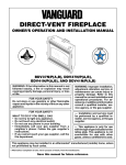
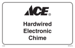
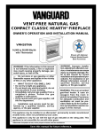
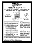
INTERNATIONAL
INSTALLATION INSTRUCTIONS
FOR PC-BDV37N (02267)
CONVERSION KIT
NATURAL GAS TO PROPANE/LP GAS
For Use When Converting Models BDV37N Series
This conversion kit must be installed by a qualified service agency.
REMOVING GLASS DOOR
1.
Read these instructions completely before installing this conversion kit.
Before proceeding, make sure the gas control valve is in the “OFF” position, all electrical
power to the appliance is OFF, and the fireplace is cool to the touch.
2.
CAUTION: The gas supply shall be shut off prior to disconnecting the
electrical power before proceeding with the conversion.
3.
Parts included with this kit:
Part No.
Description
Instruction Sheet
106040-02
Pilot Orifice
104504-02
Burner, Propane/LP
104506-02
Main Burner Orifice (1.32mm)
105838-02
Gas Valve Regulator
105801-09
Conversion Label, English
106038-09
Conversion Label, French
106080-01
Conversion Information Label
Tools Required
• 10mm Open End Wrench
• 12mm Open End Wrench
• 5/16" Socket or Nut Driver
• 18mm Open End Wrench or
Adjustable Wrench
• 3/4" Open End Wrench or
Adjustable Wrench
• 7/8" Open End Wrench or
Channel Lock Pliers
Quantity
1
1
1
1
1
1
1
1
• Torx T20 or Slotted Screwdriver
• 3/8" Socket or Nut Driver or
Slotted Screwdriver
• #2 Phillips Screwdriver
• High Temperature Silicone Sealant
(GE RTV 106/Loctite RTV 81585)
• Thread Sealant (Resistant to Propane/LP)
If any of these pieces are missing or damaged, contact the dealer where you purchased this
kit or DESA International at 1-800-972-7879 for referral information.
Remove the upper louver panel by lifting upward and out (see Figure 1).
Using a 3/8" socket or slotted screwdriver remove the screws from the three
tabs at the top of the glass door (see
Figure 2, page 2). Hold glass door securely to keep it from falling forward.
Grasp door by both sides and ease it
upward off the lower bracket (see Figure 2, page 2).
Top Louver Panel
Figure 1 - Removing Top Louver Panel
PC-BDV37N (02267) Conversion Kit
Screw
3.
Glass Door
Assembly
4.
Lower Bracket for
Glass Door Assembly
Figure 2 - Removing/Replacing Glass
Door
LOG REMOVAL
Carefully remove the log set and ember
material from around the burner and place
them outside the fireplace.
BURNER, MAIN BURNER
ORIFICE, AND PILOT
ORIFICE CONVERSION
1.
2.
Open lower louver panel. This allows
access below firebox to gas line connections and gas control valve.
Disconnect flare fitting connected to the
brass elbow inside the bottom control
compartment area. Use a 3/4" open end
wrench on the flare fitting (see Figure 3).
Burner
Fireplace
Floor
5/16" hex
Mounting Screw
RTV
Silicone
5.
6.
7.
Turn brass elbow and main burner orifice counterclockwise to remove from
burner. The orifice is threaded into the
burner inlet. The elbow may have a
slight resistance since the orifice has
been sealed with RTV silicone. Use a
7/8" open end wrench or channel lock
pliers for elbow and orifice removal.
Remove existing main burner orifice from
brass elbow and replace with main burner
orifice supplied with conversion kit.
Note: The new main burner orifice will
have the number 132 stamped on it for
identification purposes. Apply a small
amount of thread sealant to the orifice
before tightening (see Figure 4). Sealant
must be resistant to Propane/LP gas.
Remove the burner by loosening the
two 5/16" hex mounting screws (see
Figure 3). Lift burner up and out.
Convert the pilot burner by changing out
the pilot orifice. Remove the compression nut and compression sleeve from
the pilot. Remove the pilot orifice from
inside the pilot barrel (see Figure 5). Replace with the pilot orifice supplied with
this kit. Note: The new pilot orifice has
the number 30 stamped on it for identification purposes.
Place open end of pilot orifice on top
of compression sleeve and carefully
slide up inside pilot burner. Tighten
compression nut (see Figure 5).
IMPORTANT: Be careful not to bend
or kink aluminum tubing during conversion. Make sure the compression sleeve
and pilot orifice are properly mated and
aligned before retightening the compression nut.
8.
Replace original burner with burner
supplied with kit. Attach with the two
5/16" hex mounting screws removed in
step 5.
9. Attach main burner orifice and brass
elbow assembly to burner. Place main
burner orifice into threaded end of
burner and turn clockwise to tighten
(see Figure 3). Align the brass elbow
with the flare fitting on the aluminum
tubing.
10. Reconnect the aluminum tube flare fitting onto the brass elbow (see Figure 3).
11. Reapply RTV silicone to seal area where
orifice passes through the bottom combustion chamber (see Figure 3).
Thermopile
Pilot Burner
Piezo Ignitor
Thermocouple
12mm
Hex
Pilot Orifice
Compression
Sleeve
Compression Nut
(10mm Hex)
Figure 5 - Removing/Replacing Pilot
Orifice
Main Burner
Orifice (18mm
Hex)
Main Burner
Orifice
Brass Elbow
Aluminum Tubing
Apply Thread
Sealant Here
Only
Flare Fitting
Figure 3 - Removing/Replacing Main
Burner Orifice, Brass Elbow, and
Aluminum Tubing
Brass Elbow
Figure 4 - Removing/Replacing Main
Burner Orifice
2
105822
INSTALLATION INSTRUCTIONS
GAS CONTROL VALVE
CONVERSION
CONVERSION LABELING
AND PLACEMENT
Convert the gas control valve by swapping
out the valve regulator portion of the gas
valve.
1. Using a TORX T20 or slotted screwdriver, remove and discard the three
mounting screws, pressure regulator
tower, and diaphragm/spring components (see Figure 6).
2. Insure that the rubber gasket is properly positioned on the new pressure
regulator assembly. Install the new
pressure regulator assembly to the valve
using the new mounting screws supplied with the kit. Tighten screws securely (approximately 25in-lbs.) (see
Figure 7).
3. Install the identification label enclosed
with the gas valve regulator to the valve
body where it can easily be seen (see
Figure 7).
1.
Mounting
Screws
Lighting Instruction
Plate
Figure 8 - Applying English and French
Conversion Labels over Existing
Certification Labels on Lighting
Instruction Plate
H
I
LO
2.
Apply the English and French conversion labels over the top of the existing
certification labels (see Figure 8). Existing certification labels are located on
the lighting instruction plate inside the
gas valve compartment area. With permanent ink, print the previous model
number on the label in the space provided (see Figure 9).
After filling in the data required on the
conversion information label, affix it to
the floor of the appliance where it is
easily seen when the bottom louver
panel is opened (see Figure 10).
French This
Side
English This
Side
DIRECT VENT DECORATIVE FIREPLACE
Mounting Screws
Conversion Kit Model
Type of Gas
O
LO
OT O
H
I
PIL
N
FF
Pressure
Regulator
Tower
Rubber Gasket
®
Diaphragm/
Spring
Components
Previous Model #
Figure 9 - Print Previous Model Number
on Conversion Labels
Identification Label
Figure 7 - Installing Pressure Regulator
Assembly
CONVERSION INFORMATION LABEL
This appliance was converted on
O
PIL
N
FF
–
OT O
Day
–
Month
to
gas
Year
with Kit No.
by
(name and address of organization making
this conversion), which accepts the
responsibility that this conversion has been
properly made.
56060
106080-01
Figure 10 - Conversion Information Label
Figure 6 - Removing Mounting Screws,
Pressure Regulator Tower, and
Diaphragm/Spring Components
105822
3
FINAL PREPARATION
1.
2.
Replace logs and embers back into the
correct positions as instructed in your
appliance Owner’s Manual.
Reinstall glass door and upper louver
panel on fireplace. To do so, reverse the
instructions under Removing Glass
Door on page 1.
The conversion is now complete.
Refer to the section on Checking Gas Connections and Operating Fireplace in your
appliance Owner’s Manual.
WARNING: Test all gas piping and connections for leaks
after installing or servicing. Correct leaks at once.
WARNING: Never use an open
flame to check for a leak. Apply
commercial leak test solution to
all gas joints. Bubbles forming
show a leak. Correct all leaks at
once.
WARNING: This conversion
kit shall be installed by a qualified service agency in accordance
with the manufacturer’s instructions and all applicable codes
and requirements of the authority having jurisdiction. If the information in these instruction is
not followed exactly, a fire, explosion, or production of carbon
monoxide may result causing
property damage, personal injury,
or loss of life. The qualified service agency is responsible for
the proper installation of this kit.
The installation is not proper and
complete until the operation of
the converted appliance is
checked as specified in the
manufacturer’s instructions supplied with the kit.
INTERNATIONAL
2701 Industrial Drive
Bowling Green, KY 42101
www.desatech.com
105822 01
55877
NOT A UPC
105822-01
REV. B
09/99