1
DELTA ELECTRONICS CO., LTD.
PCI-DMC-A01
PCI-DMC-B01
High-Speed PCI 12-Axis Motion Control Card
Programming Manual
Version: 1.11.1
PCI-DMC-A01 / PCI-DMC-B01 Programming Manual
About this Manual
User Information
Please keep this manual in a safe place.
This manual is subject to change without notice due to the release of new products,
improvements and changes in technologies, and/or modifications to data and forms.
This manual may not be copied or reproduced in whole or in part without the express written
consent of Delta Electronics.
Trademarks
Windows NT/2000/XP, Visual Studio, Visual C++, Visual BASIC are all registered trademarks of
Microsoft Corporation.
BCB (Borland C++ Builder) is a registered trademark of Borland Corporation.
The names of other products are only used for identification purposes and the registered
trademarks remain the property of their respective owners.
Technical Support and Service
If you require technical support, service, or other information, or should you have any questions
about the use of this product, please visit our website
(http://www.delta.com.tw/industrialautomation) or contact us directly. We look forward to providing
you the best possible support and service. Our contact details are provided below.
ASIA
DELTA ELECTRONICS, INC.
Taoyuan Plant 1
31-1, XINGBANG ROAD,
GUISHAN INDUSTRIAL ZONE,
TAOYUAN COUNTY 33370, TAIWAN, R.O.C.
TEL: 886-3-362-6301
FAX: 886-3-362-7267
JAPAN
DELTA ELECTRONICS (JAPAN), INC.
Tokyo Office
DELTA SHIBADAIMON BUILDING
2-1-14 SHIBADAIMON, MINATO-KU,
TOKYO, 105-0012, JAPAN
TEL: 81-3-5733-1111
FAX: 81-3-5733-1211
NORTH/SOUTH AMERICA
DELTA PRODUCTS CORPORATION (USA)
Raleigh Office
P.O. BOX 12173
5101 DAVIS DRIVE,
RESEARCH TRIANGLE PARK, NC 27709, U.S.A.
TEL: 1-919-767-3813
FAX: 1-919-767-3969
EUROPE
DELTRONICS (THE NETHERLANDS) B.V.
Eindhoven Office
DE WITBOGT 15, 5652 AG EINDHOVEN,
THE NETHERLANDS
TEL: 31-40-259-2850
FAX: 31-40-259-2851
Revised March, 2012
i
PCI-DMC-A01 / PCI-DMC-B01 Programming Manual
Table of Contents
Chapter 1 Introduction to the API Function Library --------------------------------------------------- 1-1
1.1
Using the Function Libraries---------------------------------------------------------------------- 1-1
1.2
Edit New Project ------------------------------------------------------------------------------------- 1-1
1.2.1
1.2.2
1.2.3
1.2.4
1.2.5
1.2.6
Using VC ----------------------------------------------------------------------------------- 1-1
Using Borland C -------------------------------------------------------------------------- 1-1
Using VB ------------------------------------------------------------------------------------ 1-2
Using Delphi ------------------------------------------------------------------------------- 1-2
Using VB.Net ------------------------------------------------------------------------------ 1-2
Using C# ------------------------------------------------------------------------------------ 1-2
Chapter 2 Command Return Values and Messages --------------------------------------------------- 2-1
2.1
Error Codes ------------------------------------------------------------------------------------------- 2-1
2.2
Error Code Example -------------------------------------------------------------------------------- 2-4
Chapter 3 Operating Principles ------------------------------------------------------------------------------- 3-1
3.1
Card Initialization ------------------------------------------------------------------------------------ 3-1
3.1.1
3.1.2
3.2
Read/Write Driver Parameters ------------------------------------------------------------------- 3-4
3.2.1
3.2.2
3.3
Function List ------------------------------------------------------------------------------3-13
Sample Application----------------------------------------------------------------------3-13
Velocity Motion Control (1)-----------------------------------------------------------------------3-16
3.6.1
3.6.2
ii
Overview ------------------------------------------------------------------------------------ 3-9
Function List ------------------------------------------------------------------------------3-10
Sample Application----------------------------------------------------------------------3-10
Torque Motion Control ----------------------------------------------------------------------------3-13
3.5.1
3.5.2
3.6
Function List ------------------------------------------------------------------------------- 3-7
Sample Application----------------------------------------------------------------------- 3-7
Homing Motion Control ---------------------------------------------------------------------------- 3-9
3.4.1
3.4.2
3.4.3
3.5
Function List ------------------------------------------------------------------------------- 3-4
Sample Application----------------------------------------------------------------------- 3-4
CANopen Protocol ---------------------------------------------------------------------------------- 3-7
3.3.1
3.3.2
3.4
Function List ------------------------------------------------------------------------------- 3-1
Sample Application----------------------------------------------------------------------- 3-1
Function List ------------------------------------------------------------------------------3-16
Sample Application----------------------------------------------------------------------3-16
Revised March, 2012
PCI-DMC-A01 / PCI-DMC-B01 Programming Manual
3.7
Velocity Motion Control (2)-----------------------------------------------------------------------3-19
3.7.1
3.7.2
3.8
Point to Point Motion Control --------------------------------------------------------------------3-21
3.8.1
3.8.2
3.8.3
3.9
Overview -----------------------------------------------------------------------------------3-21
Function List ------------------------------------------------------------------------------3-21
Sample Application----------------------------------------------------------------------3-22
Linear Interpolation Motion Control ------------------------------------------------------------3-26
3.9.1
3.9.2
3.9.3
3.10
Function List ------------------------------------------------------------------------------3-19
Sample Application----------------------------------------------------------------------3-19
Overview -----------------------------------------------------------------------------------3-26
Function List ------------------------------------------------------------------------------3-26
Sample Application----------------------------------------------------------------------3-27
Arc Interpolation Motion Control ----------------------------------------------------------------3-31
3.10.1 Overview -----------------------------------------------------------------------------------3-31
3.10.2 Function List ------------------------------------------------------------------------------3-31
3.10.3 Sample Application----------------------------------------------------------------------3-32
3.11
Spiral Interpolation Motion Control -Helix ----------------------------------------------------3-37
3.11.1 Function List ------------------------------------------------------------------------------3-37
3.11.2 Sample Application----------------------------------------------------------------------3-37
3.12
Continuous Interpolation Motion Control -----------------------------------------------------3-42
3.12.1 Overview -----------------------------------------------------------------------------------3-42
3.12.2 Function List ------------------------------------------------------------------------------3-42
3.12.3 Sample Application----------------------------------------------------------------------3-43
3.13
Software Limit Control ----------------------------------------------------------------------------3-47
3.13.1 Function List ------------------------------------------------------------------------------3-47
3.13.2 Sample Application----------------------------------------------------------------------3-47
3.14
Synchronization Motion Control ----------------------------------------------------------------3-51
3.14.1 Function List ------------------------------------------------------------------------------3-51
3.14.2 Sample Application----------------------------------------------------------------------3-51
3.15
Dwell Command ------------------------------------------------------------------------------------3-55
3.15.1 Function List ------------------------------------------------------------------------------3-55
3.15.2 Sample Application----------------------------------------------------------------------3-55
3.16
Change Position ------------------------------------------------------------------------------------3-57
3.16.1 Function List ------------------------------------------------------------------------------3-57
3.16.2 Sample Application----------------------------------------------------------------------3-57
3.17
Change Position ------------------------------------------------------------------------------------3-60
3.17.1 Function List ------------------------------------------------------------------------------3-60
3.17.2 Sample Application----------------------------------------------------------------------3-60
Revised March, 2012
iii
PCI-DMC-A01 / PCI-DMC-B01 Programming Manual
3.18
Change Velocity ------------------------------------------------------------------------------------3-63
3.18.1 Function List ------------------------------------------------------------------------------3-63
3.18.2 Sample Application----------------------------------------------------------------------3-63
3.19
Remote I/O Module-I/O Port---------------------------------------------------------------------3-67
3.19.1 Function List ------------------------------------------------------------------------------3-67
3.19.2 Sample Application----------------------------------------------------------------------3-67
3.20
Remote I/O Module- Manual Pulse Generator (1) -----------------------------------------3-70
3.20.1 Function List ------------------------------------------------------------------------------3-70
3.20.2 Sample Application----------------------------------------------------------------------3-70
3.21
Remote I/O Module- Manual Pulse Generator (2) -----------------------------------------3-73
3.21.1 Function List ------------------------------------------------------------------------------3-73
3.21.2 Sample Application----------------------------------------------------------------------3-73
3.22
Remote Pulse Interface Module -Mode 1 ----------------------------------------------------3-76
3.22.1 Function List ------------------------------------------------------------------------------3-76
3.22.2 Sample Application----------------------------------------------------------------------3-77
3.23
Remote Pulse Interface Module -Mode 2 ----------------------------------------------------3-83
3.23.1 Function List ------------------------------------------------------------------------------3-83
3.23.2 Sample Application----------------------------------------------------------------------3-83
3.24
Get (Calculate) Arc Information-----------------------------------------------------------------3-87
3.24.1 Function List ------------------------------------------------------------------------------3-87
3.24.2 Sample Application----------------------------------------------------------------------3-87
3.25
Control Interrupt ------------------------------------------------------------------------------------3-90
3.25.1 Function List ------------------------------------------------------------------------------3-90
3.25.2 Sample Application----------------------------------------------------------------------3-90
3.26
MasterCard Security-------------------------------------------------------------------------------3-94
3.26.1 Function List ------------------------------------------------------------------------------3-94
3.26.2 Sample Application----------------------------------------------------------------------3-95
3.27
Remote Analog Input/Output Module ------------------------------------------------------- 3-100
3.27.1 Function List ---------------------------------------------------------------------------- 3-100
3.27.2 Sample Application-------------------------------------------------------------------- 3-101
3.28
Spiral Interpolation Motion Control -Spiral ------------------------------------------------- 3-106
3.28.1 Function List ---------------------------------------------------------------------------- 3-106
3.28.2 Sample Application-------------------------------------------------------------------- 3-106
3.29
Position Compare -------------------------------------------------------------------------------- 3-111
3.29.1 Function List ---------------------------------------------------------------------------- 3-111
3.29.2 Sample Application-------------------------------------------------------------------- 3-112
iv
Revised March, 2012
PCI-DMC-A01 / PCI-DMC-B01 Programming Manual
3.30
Axis Group ----------------------------------------------------------------------------------------- 3-116
3.30.1 Function List ---------------------------------------------------------------------------- 3-116
3.30.2 Sample Application-------------------------------------------------------------------- 3-116
3.31
Speed Continue ---------------------------------------------------------------------------------- 3-119
3.31.1 Function List ---------------------------------------------------------------------------- 3-119
3.31.2 Sample Application-------------------------------------------------------------------- 3-119
3.32
Spiral Interpolation - Helix Using -Sp1_ Normal Follow -------------------------------- 3-122
3.32.1 Function List ---------------------------------------------------------------------------- 3-122
3.32.2 Sample Application-------------------------------------------------------------------- 3-122
3.33
Logger ---------------------------------------------------------------------------------------------- 3-130
3.33.1 Function List ---------------------------------------------------------------------------- 3-130
3.33.2 Sample Application-------------------------------------------------------------------- 3-130
Chapter 4 Control API-------------------------------------------------------------------------------------------- 4-1
4.1
Data Type and Range ----------------------------------------------------------------------------- 4-1
4.2
Function Description ------------------------------------------------------------------------------- 4-2
Chapter 5 Hardware Initialization API ---------------------------------------------------------------------- 5-1
5.1
_DMC_01_open ------------------------------------------------------------------------------------- 5-2
5.2
_DMC_01_close ------------------------------------------------------------------------------------- 5-2
5.3
_DMC_01_get_CardNo_seq --------------------------------------------------------------------- 5-3
5.4
_DMC_01_pci_initial ------------------------------------------------------------------------------- 5-4
5.5
_DMC_01_get_card_version --------------------------------------------------------------------- 5-4
Chapter 6 Interface API ------------------------------------------------------------------------------------------ 6-1
6.1
_DMC_01_initial_bus ------------------------------------------------------------------------------ 6-2
6.2
_DMC_01_start_ring ------------------------------------------------------------------------------- 6-2
6.3
_DMC_01_get_device_table --------------------------------------------------------------------- 6-3
6.4
_DMC_01_get_node_table ----------------------------------------------------------------------- 6-3
6.5
_DMC_01_check_card_running ----------------------------------------------------------------- 6-4
6.6
_DMC_01_reset_card ----------------------------------------------------------------------------- 6-4
6.7
_DMC_01_check_nodeno ------------------------------------------------------------------------ 6-5
6.8
_DMC_01_get_master_connect_status ------------------------------------------------------- 6-6
6.9
_DMC_01_get_mailbox_Error ------------------------------------------------------------------- 6-6
6.10
_DMC_01_get_mailbox_cnt ---------------------------------------------------------------------- 6-7
6.11
_DMC_01_get_dsp_cnt --------------------------------------------------------------------------- 6-7
6.12
_DMC_01_set_dio_output ------------------------------------------------------------------------ 6-8
6.13
_DMC_01_get_dio_output ------------------------------------------------------------------------ 6-8
Revised March, 2012
v
PCI-DMC-A01 / PCI-DMC-B01 Programming Manual
6.14
_DMC_01_get_dio_input -------------------------------------------------------------------------- 6-9
6.15
_DMC_01_get_cycle_time ------------------------------------------------------------------------ 6-9
6.16
_DMC_01_initial_bus2 ----------------------------------------------------------------------------6-10
6.17
_DMC_01_motion_cnt ----------------------------------------------------------------------------6-10
Chapter 7 Servo Drive Parameter Read/Write API ------------------------------------------------------ 7-1
7.1
_DMC_01_read_servo_parameter ------------------------------------------------------------- 7-2
7.2
_DMC_01_write_servo_parameter ------------------------------------------------------------- 7-3
Chapter 8 Using SDO Protocol API -------------------------------------------------------------------------- 8-1
8.1
CANopen SDO protocol --------------------------------------------------------------------------- 8-2
8.2
_DMC_01_check_canopen_lock ---------------------------------------------------------------- 8-6
8.3
_DMC_01_get_canopen_ret --------------------------------------------------------------------- 8-7
8.4
_DMC_01_set_pdo_mode ------------------------------------------------------------------------ 8-8
8.5
_DMC_01_send_message ----------------------------------------------------------------------- 8-9
8.6
_DMC_01_send_message3 ---------------------------------------------------------------------8-10
8.7
_DMC_01_read_message -----------------------------------------------------------------------8-11
8.8
_DMC_01_read_message2 ---------------------------------------------------------------------8-12
8.9
_DMC_01_get_message -------------------------------------------------------------------------8-13
8.10
_DMC_01_reset_sdo_choke --------------------------------------------------------------------8-14
8.11
_DMC_01_get_sdo_retry_history --------------------------------------------------------------8-14
Chapter 9 Point to Point Motion Control Packet Protocol API ------------------------------------- 9-1
9.1
_DMC_01_set_sdo_driver_speed_profile ---------------------------------------------------- 9-2
9.2
_DMC_01_start_sdo_driver_r_move----------------------------------------------------------- 9-3
9.3
_DMC_01_start_sdo_driver_a_move ---------------------------------------------------------- 9-4
9.4
_DMC_01_start_sdo_driver_new_position_move ------------------------------------------ 9-5
Chapter 10 Homing Motion Control Packet Protocol API -------------------------------------------10-1
10.1
_DMC_01_set_home_config --------------------------------------------------------------------10-2
10.2
_DMC_01_set_home_move---------------------------------------------------------------------10-7
10.3
_DMC_01_escape_home_move ---------------------------------------------------------------10-8
Chapter 11 Velocity Motion Control Packet Protocol API -------------------------------------------11-1
vi
11.1
_DMC_01_set_velocity_mode ------------------------------------------------------------------11-2
11.2
_DMC_01_set_velocity ---------------------------------------------------------------------------11-3
11.3
_DMC_01_set_velocity_stop --------------------------------------------------------------------11-4
11.4
_DMC_01_set_velocity_torque_limit ----------------------------------------------------------11-5
Revised March, 2012
PCI-DMC-A01 / PCI-DMC-B01 Programming Manual
Chapter 12 Torque Motion Control Packet Protocol API --------------------------------------------12-1
12.1
_DMC_01_set_torque_mode -------------------------------------------------------------------12-2
12.2
_DMC_01_set_torque ----------------------------------------------------------------------------12-3
12.3
_DMC_01_set_torque_stop ---------------------------------------------------------------------12-4
12.4
_DMC_01_set_torque_velocity_limit ----------------------------------------------------------12-5
Chapter 13 Using PDO Protocol API -----------------------------------------------------------------------13-1
13.1
_DMC_01_ipo_set_svon -------------------------------------------------------------------------13-2
13.2
_DMC_01_get_buffer_length -------------------------------------------------------------------13-3
13.3
_DMC_01_command_buf_clear----------------------------------------------------------------13-4
13.4
_DMC_01_buf_dwell ------------------------------------------------------------------------------13-5
13.5
_DMC_01_set_group -----------------------------------------------------------------------------13-6
Chapter 14 Stop Motion Control API -----------------------------------------------------------------------14-1
14.1
_DMC_01_emg_stop -----------------------------------------------------------------------------14-2
14.2
_DMC_01_sd_stop --------------------------------------------------------------------------------14-3
14.3
_DMC_01_sd_abort -------------------------------------------------------------------------------14-4
14.4
_DMC_01_set_sd_mode -------------------------------------------------------------------------14-5
Chapter 15 Motion Status API --------------------------------------------------------------------------------15-1
15.1
_DMC_01_motion_done -------------------------------------------------------------------------15-2
15.2
_DMC_01_motion_status ------------------------------------------------------------------------15-3
Chapter 16 Motion Counter Value API ---------------------------------------------------------------------16-1
16.1
_DMC_01_get_command ------------------------------------------------------------------------16-2
16.2
_DMC_01_set_command ------------------------------------------------------------------------16-2
16.3
_DMC_01_get_position---------------------------------------------------------------------------16-3
16.4
_DMC_01_set_position ---------------------------------------------------------------------------16-3
16.5
_DMC_01_get_target_pos -----------------------------------------------------------------------16-4
16.6
_DMC_01_get_torque ----------------------------------------------------------------------------16-5
16.7
_DMC_01_get_current_speed ------------------------------------------------------------------16-6
16.8
_DMC_01_get_current_speed_rpm -----------------------------------------------------------16-7
Chapter 17 Software Limit API -------------------------------------------------------------------------------17-1
17.1
_DMC_01_set_soft_limit -------------------------------------------------------------------------17-2
17.2
_DMC_01_enable_soft_limit --------------------------------------------------------------------17-3
17.3
_DMC_01_disable_soft_limit --------------------------------------------------------------------17-3
17.4
_DMC_01_get_soft_limit_status ---------------------------------------------------------------17-4
Revised March, 2012
vii
PCI-DMC-A01 / PCI-DMC-B01 Programming Manual
Chapter 18 1-Axis Motion Control API --------------------------------------------------------------------18-1
18.1
_DMC_01_start_tr_move ------------------------------------------------------------------------18-2
18.2
_DMC_01_start_sr_move ------------------------------------------------------------------------18-3
18.3
_DMC_01_start_ta_move ------------------------------------------------------------------------18-4
18.4
_DMC_01_start_sa_move -----------------------------------------------------------------------18-5
18.5
_DMC_01_p_change -----------------------------------------------------------------------------18-6
18.6
_DMC_01_v_change ------------------------------------------------------------------------------18-7
18.7
_DMC_01_start_tr_move_2seg ----------------------------------------------------------------18-9
18.8
_DMC_01_start_sr_move_2seg-------------------------------------------------------------- 18-11
18.9
_DMC_01_start_ta_move_2seg-------------------------------------------------------------- 18-12
18.10 _DMC_01_start_sa_move_2seg ------------------------------------------------------------- 18-13
18.11 _DMC_01_start_tr_move_2seg2------------------------------------------------------------- 18-14
18.12 _DMC_01_start_sr_move_2seg2 ------------------------------------------------------------ 18-16
18.13 _DMC_01_start_ta_move_2seg2 ------------------------------------------------------------ 18-17
18.14 _DMC_01_start_sa_move_2seg2 ----------------------------------------------------------- 18-18
18.15 _DMC_01_feedrate_overwrite ---------------------------------------------------------------- 18-19
18.16 _DMC_01_start_v3_move --------------------------------------------------------------------- 18-21
Chapter 19 2-Axis Linear Interpolation Motion Control API ----------------------------------------19-1
19.1
_DMC_01_start_tr_move_xy --------------------------------------------------------------------19-2
19.2
_DMC_01_start_sr_move_xy -------------------------------------------------------------------19-4
19.3
_DMC_01_start_ta_move_xy -------------------------------------------------------------------19-6
19.4
_DMC_01_start_sa_move_xy ------------------------------------------------------------------19-8
19.5
_DMC_01_start_v3_move_xy ---------------------------------------------------------------- 19-10
Chapter 20 2-Axis Arc Interpolation Motion Control API --------------------------------------------20-1
20.1
_DMC_01_start_tr_arc_xy -----------------------------------------------------------------------20-3
20.2
_DMC_01_start_sr_arc_xy ----------------------------------------------------------------------20-5
20.3
_DMC_01_start_ta_arc_xy ----------------------------------------------------------------------20-7
20.4
_DMC_01_start_sa_arc_xy----------------------------------------------------------------------20-9
20.5
_DMC_01_start_tr_arc2_xy ------------------------------------------------------------------- 20-11
20.6
_DMC_01_start_sr_arc2_xy------------------------------------------------------------------- 20-13
20.7
_DMC_01_start_ta_arc2_xy------------------------------------------------------------------- 20-15
20.8
_DMC_01_start_sa_arc2_xy ------------------------------------------------------------------ 20-17
20.9
_DMC_01_start_tr_arc3_xy ------------------------------------------------------------------- 20-19
20.11 _DMC_01_start_ta_arc3_xy------------------------------------------------------------------- 20-23
20.12 _DMC_01_start_sa_arc3_xy ------------------------------------------------------------------ 20-25
viii
Revised March, 2012
PCI-DMC-A01 / PCI-DMC-B01 Programming Manual
20.13 _DMC_01_start_spiral_xy --------------------------------------------------------------------- 20-27
20.14 _DMC_01_start_spiral2_xy -------------------------------------------------------------------- 20-29
20.15 _DMC_01_start_v3_arc_xy-------------------------------------------------------------------- 20-31
20.16 _DMC_01_start_v3_arc2_xy ------------------------------------------------------------------ 20-33
20.17 _DMC_01_start_v3_arc3_xy ------------------------------------------------------------------ 20-35
20.18 _DMC_01_start_v3_spiral_xy----------------------------------------------------------------- 20-37
20.19 _DMC_01_start_v3_spiral2_xy --------------------------------------------------------------- 20-39
Chapter 21 3-Axis Linear Interpolation Motion Control API ----------------------------------------21-1
21.1
_DMC_01_start_tr_move_xyz ------------------------------------------------------------------21-2
21.2
_DMC_01_start_sr_move_xyz------------------------------------------------------------------21-3
21.3
_DMC_01_start_ta_move_xyz------------------------------------------------------------------21-4
21.4
_DMC_01_start_sa_move_xyz -----------------------------------------------------------------21-5
21.5
_DMC_01_start_v3_move_xyz -----------------------------------------------------------------21-6
Chapter 22 3-Axis Spiral Interpolation Motion Control API ----------------------------------------22-1
22.1
_DMC_01_start_tr_heli_xy ----------------------------------------------------------------------22-2
22.2
_DMC_01_start_sr_heli_xy ----------------------------------------------------------------------22-4
22.3
_DMC_01_start_ta_heli_xy ----------------------------------------------------------------------22-6
22.4
_DMC_01_start_sa_heli_xy ---------------------------------------------------------------------22-8
22.5
_DMC_01_start_v3_heli_xy ------------------------------------------------------------------- 22-10
Chapter 23 Velocity Motion Control API ------------------------------------------------------------------23-1
23.1
_DMC_01_tv_move -------------------------------------------------------------------------------23-2
23.2
_DMC_01_sv_move -------------------------------------------------------------------------------23-3
Chapter 24 Synchronization Motion Control API ------------------------------------------------------24-1
24.1
_DMC_01_sync_move----------------------------------------------------------------------------24-2
24.2
_DMC_01_sync_move_config ------------------------------------------------------------------24-2
Chapter 25 Remote Module Control API ------------------------------------------------------------------25-1
25.1
_DMC_01_get_rm_input_value ----------------------------------------------------------------25-2
25.2
_DMC_01_set_rm_input_filter ------------------------------------------------------------------25-3
25.3
_DMC_01_set_rm_input_filter_enable -------------------------------------------------------25-4
25.4
_DMC_01_set_rm_output_value ---------------------------------------------------------------25-5
25.5
_DMC_01_set_rm_output_value_error_handle --------------------------------------------25-6
25.6
_DMC_01_get_rm_output_value---------------------------------------------------------------25-7
25.7
_DMC_01_get_rm_output_value_error_handle --------------------------------------------25-8
Revised March, 2012
ix
PCI-DMC-A01 / PCI-DMC-B01 Programming Manual
25.8
_DMC_01_set_rm_output_active --------------------------------------------------------------25-9
Chapter 26 MPG and JOG Operation API-----------------------------------------------------------------26-1
26.1
_DMC_01_set_rm_mpg_axes_enable -------------------------------------------------------26-2
26.2
_DMC_01_set_rm_mpg_axes_enable2 ------------------------------------------------------26-4
26.3
_DMC_01_set_rm_jog_axes_enable ---------------------------------------------------------26-6
Chapter 27 4-Channel Pulse Interface API ---------------------------------------------------------------27-1
27.1
_DMC_01_set_rm_04pi_ipulse_mode --------------------------------------------------------27-2
27.2
_DMC_01_set_rm_04pi_opulse_mode -------------------------------------------------------27-3
27.3
_DMC_01_set_rm_04pi_svon_polarity -------------------------------------------------------27-4
27.4
_DMC_01_set_rm_04pi_DO2 ------------------------------------------------------------------27-5
27.5
_DMC_01_set_rm_04pi_homing_ratio -------------------------------------------------------27-6
27.6
_DMC_01_04pi_set_poweron ------------------------------------------------------------------27-7
27.7
_DMC_01_rm_04PI_get_buffer ----------------------------------------------------------------27-8
Chapter 28 4-Channel Pulse Interface (Mode 1) Motion Control API ----------------------------28-1
28.1
_DMC_01_rm_04pi_md1_start_move --------------------------------------------------------28-3
28.2
_DMC_01_rm_04pi_md1_v_move ------------------------------------------------------------28-5
28.3
_DMC_01_rm_04pi_md1_start_line2 ---------------------------------------------------------28-6
28.4
_DMC_01_rm_04pi_md1_start_line3 ---------------------------------------------------------28-8
28.5
_DMC_01_rm_04pi_md1_start_line4 ------------------------------------------------------- 28-10
28.6
_DMC_01_rm_04pi_md1_start_arc --------------------------------------------------------- 28-12
28.7
_DMC_01_rm_04pi_md1_start_arc2 ------------------------------------------------------- 28-14
28.8
_DMC_01_rm_04pi_md1_start_arc3 ------------------------------------------------------- 28-16
28.9
_DMC_01_rm_04pi_md1_start_heli--------------------------------------------------------- 28-18
28.10 _DMC_01_rm_04pi_md1_p_change-------------------------------------------------------- 28-20
28.11 _DMC_01_rm_04pi_md1_v_change -------------------------------------------------------- 28-21
28.12 _DMC_01_rm_04pi_md1_set_gear --------------------------------------------------------- 28-22
28.13 _DMC_01_rm_04pi_md1_set_soft_limit --------------------------------------------------- 28-23
28.14 _DMC_01_rm_04pi_md1_get_soft_limit_status ----------------------------------------- 28-24
28.15 _DMC_01_rm_04pi_md1_set_sld ----------------------------------------------------------- 28-25
28.16 _DMC_01_rm_04pi_md1_get_mc_error_code ------------------------------------------- 28-26
28.17 _DMC_01_set_rm_04pi_ref_counter ------------------------------------------------------- 28-27
Chapter 29 4-Channel Analog Output Remote Module API ----------------------------------------29-1
x
29.1
_DMC_01_rm_04da_set_output_value ------------------------------------------------------29-2
29.2
_DMC_01_rm_04da_get_output_value ------------------------------------------------------29-3
Revised March, 2012
PCI-DMC-A01 / PCI-DMC-B01 Programming Manual
29.3
_DMC_01_rm_04da_get_return_code -------------------------------------------------------29-4
29.4
_DMC_01_rm_04da_set_output_range ------------------------------------------------------29-5
29.5
_DMC_01_rm_04da_set_output_enable-----------------------------------------------------29-6
29.6
_DMC_01_rm_04da_set_output_overrange ------------------------------------------------29-7
29.7
_DMC_01_rm_04da_set_output_error_clear -----------------------------------------------29-8
29.8
_DMC_01_rm_04da_read_data ----------------------------------------------------------------29-9
29.9
_DMC_01_rm_04da_set_output_error_handle ------------------------------------------- 29-10
29.10 _DMC_01_rm_04da_set_output_offset_value ------------------------------------------- 29-11
29.11 _DMC_01_rm_04da_get_output_offset_value ------------------------------------------- 29-12
Chapter 30 4-Channel Analog Input Remote Module API -------------------------------------------30-1
30.1
_DMC_01_set_04ad_input_range -------------------------------------------------------------30-2
30.2
_DMC_01_get_04ad_input_range -------------------------------------------------------------30-3
30.3
_DMC_01_set_04ad_zero_scale --------------------------------------------------------------30-4
30.4
_DMC_01_get_04ad_zero_scale_status ----------------------------------------------------30-5
30.5
_DMC_01_set_04ad_full_scale ----------------------------------------------------------------30-6
30.6
_DMC_01_get_04ad_full_scale_status ------------------------------------------------------30-7
30.7
_DMC_01_set_04ad_conversion_time -------------------------------------------------------30-8
30.8
_DMC_01_get_04ad_conversion_time -------------------------------------------------------30-9
30.9
_DMC_01_get_04ad_data --------------------------------------------------------------------- 30-10
30.10 _DMC_01_set_04ad_average_mode ------------------------------------------------------- 30-11
30.11 _DMC_01_get_04ad_average_mode------------------------------------------------------- 30-12
30.12 _DMC_01_set_04ad_input_enable---------------------------------------------------------- 30-13
Chapter 31 Slave Data API ------------------------------------------------------------------------------------31-1
31.1
_DMC_01_get_devicetype-----------------------------------------------------------------------31-2
31.2
_DMC_01_get_slave_version-------------------------------------------------------------------31-4
Chapter 32 Parameter Monitoring API ---------------------------------------------------------------------32-1
32.1
_DMC_01_set_monitor ---------------------------------------------------------------------------32-2
32.2
_DMC_01_get_monitor ---------------------------------------------------------------------------32-5
32.3
_DMC_01_get_servo_command ---------------------------------------------------------------32-6
32.4
_DMC_01_get_servo_DI -------------------------------------------------------------------------32-7
32.5
_DMC_01_get_servo_DO -----------------------------------------------------------------------32-8
Chapter 33 Alarm Message API ------------------------------------------------------------------------------33-1
33.1
_DMC_01_set_ralm -------------------------------------------------------------------------------33-2
33.2
_DMC_01_get_alm_code ------------------------------------------------------------------------33-3
Revised March, 2012
xi
PCI-DMC-A01 / PCI-DMC-B01 Programming Manual
33.3
_DMC_01_master_alm_code -------------------------------------------------------------------33-4
33.4
_DMC_01_slave_error ----------------------------------------------------------------------------33-5
Chapter 34 Multi-Axis Motion Control API ---------------------------------------------------------------34-1
34.1
_DMC_01_multi_axes_move -------------------------------------------------------------------34-2
34.2
_ DMC_01_liner_speed_master----------------------------------------------------------------34-4
34.3
_DMC_01_start_v3_multi_axes ----------------------------------------------------------------34-5
Chapter 35 Buffer Operation API ----------------------------------------------------------------------------35-1
35.1
_DMC_01_set_trigger_buf_function-----------------------------------------------------------35-2
Chapter 36 Interrupt API ---------------------------------------------------------------------------------------36-1
36.1
_DMC_01_ set_int_factor ------------------------------------------------------------------------36-2
36.2
_DMC_01_ int_enable ----------------------------------------------------------------------------36-3
36.3
_DMC_01_ int_disable ---------------------------------------------------------------------------36-3
36.4
_DMC_01_ get_int_count ------------------------------------------------------------------------36-4
36.5
_DMC_01_ get_int_status -----------------------------------------------------------------------36-5
36.6
_DMC_01_link_ interrupt -------------------------------------------------------------------------36-6
Chapter 37 Security API ----------------------------------------------------------------------------------------37-1
37.1
_DMC_01_ read_security ------------------------------------------------------------------------37-2
37.2
_DMC_01_ read_security_status --------------------------------------------------------------37-2
37.3
_DMC_01_write_security ------------------------------------------------------------------------37-3
37.4
_DMC_01_ write_security_status --------------------------------------------------------------37-3
37.5
_DMC_01_ check_userpassword --------------------------------------------------------------37-4
37.6
_DMC_01_write_ userpassword ---------------------------------------------------------------37-4
37.7
_DMC_01_check_verifykey ---------------------------------------------------------------------37-5
37.8
_DMC_01_write_verifykey -----------------------------------------------------------------------37-5
37.9
_DMC_01_ read_serialno ------------------------------------------------------------------------37-6
37.10 misc_slave_check_userpassword -------------------------------------------------------------37-7
37.11 _misc_slave_write_userpassword -------------------------------------------------------------37-8
37.12 _misc_slave_get_serialno -----------------------------------------------------------------------37-9
37.13 _misc_security ------------------------------------------------------------------------------------ 37-10
37.14 _misc_slave_write_verifykey ------------------------------------------------------------------ 37-11
37.15 _misc_slave_check_verifykey ---------------------------------------------------------------- 37-12
37.16 _misc_slave_user_data_buffer_read ------------------------------------------------------- 37-13
37.17 _misc_slave_user_data_buffer_write ------------------------------------------------------- 37-14
37.18 _misc_slave_user_data_to_flash ------------------------------------------------------------ 37-15
xii
Revised March, 2012
PCI-DMC-A01 / PCI-DMC-B01 Programming Manual
Chapter 38 Limit Reversal API -------------------------------------------------------------------------------38-1
38.1
_ DMC_01_rm_04pi_set_MEL_polarity ------------------------------------------------------38-2
38.2
_ DMC_01_rm_04pi_get_MEL_polarity ------------------------------------------------------38-3
38.3
_ DMC_01_rm_04pi_set_PEL_polarity -------------------------------------------------------38-4
38.4
_ DMC_01_rm_04pi_get_PEL_polarity -------------------------------------------------------38-5
Chapter 39 Compare API---------------------------------------------------------------------------------------39-1
39.1
_ DMC_01_set_compare_channel_position ------------------------------------------------39-2
39.2
_DMC_01_get_compare_channel_position -------------------------------------------------39-3
39.3
_DMC_01_set_compare_ipulse_mode -------------------------------------------------------39-4
39.4
_DMC_01_set_compare_channel_direction ------------------------------------------------39-5
39.5
_DMC_01_set_compare_channel_trigger_time --------------------------------------------39-6
39.6
_DMC_01_set_compare_channel_one_shot -----------------------------------------------39-7
39.7
_DMC_01_set_compare_channel_source ---------------------------------------------------39-8
39.8
_DMC_01_channel0_position_cmp -----------------------------------------------------------39-9
39.9
_DMC_01_channel1_output_enable -------------------------------------------------------- 39-10
39.10 _DMC_01_channel1_output_mode --------------------------------------------------------- 39-11
39.11 _DMC_01_channel1_get_io_status --------------------------------------------------------- 39-13
39.12 _DMC_01_channel1_set_gpio_out ---------------------------------------------------------- 39-14
39.13 _DMC_01_channel1_position_compare_table ------------------------------------------- 39-15
39.14 _DMC_01_channel1_position_compare_table_level ----------------------------------- 39-16
39.15 _DMC_01_channel1_position_compare_table_cnt ------------------------------------- 39-17
39.16 _DMC_01_set_compare_channel_polarity ------------------------------------------------ 39-18
39.17 _DMC_01_channel0_position_cmp_by_gpio --------------------------------------------- 39-19
39.18 _DMC_01_channel1_position_re_compare_table --------------------------------------- 39-20
39.19 _DMC_01_channel1_position_re_compare_table_level ------------------------------- 39-20
Chapter 40 Linear and Arc Interpolation Motion Control API --------------------------------------40-1
40.1
_DMC_01_start_rline_xy -------------------------------------------------------------------------40-2
40.2
_DMC_01_start_rline_xyz -----------------------------------------------------------------------40-4
40.4
_DMC_01_start_v3_rline_xyz-------------------------------------------------------------------40-9
Chapter 41 Speed Continue API -----------------------------------------------------------------------------41-1
41.1
_DMC_01_speed_continue----------------------------------------------------------------------41-2
41.2
_DMC_01_speed_continue_mode ------------------------------------------------------------41-3
41.3
_DMC_01_speed_continue_combine_ratio -------------------------------------------------41-5
Revised March, 2012
xiii
PCI-DMC-A01 / PCI-DMC-B01 Programming Manual
Chapter 42 Other API--------------------------------------------------------------------------------------------42-1
xiv
42.1
_misc_app_get_circle_endpoint ----------------------------------------------------------------42-2
42.2
_misc_app_get_circle_center_point -----------------------------------------------------------42-3
42.3
_misc_set_record_debuging --------------------------------------------------------------------42-4
42.4
_misc_open_record_debuging_file ------------------------------------------------------------42-4
42.5
_DMC_01_enable_dda_mode ------------------------------------------------------------------42-5
42.6
_DMC_01_set_dda_data-------------------------------------------------------------------------42-6
42.7
_DMC_01_get_dda_cnt --------------------------------------------------------------------------42-6
Revised March, 2012
Chapter 1 Introduction to the API Function Library | PCI-DMC-A01 / PCI-DMC-B01
Chapter 1 Introduction to the
API Function Library
PCI-DMC-A01 provides a function library and dynamic-link library (DLL) which can be called upon
to perform functions as you require. The following sections will detail how you can incorporate
these function libraries into your development environment.
1.1
Using the Function Libraries
Once you have installed the program you will find two libraries under the “lib” folder. These
libraries are intended for use in Visual Studio C or Borland development environments.
Table 1.1
1.2
PCI_DMC_01.lib
Visual Studio C function
library
BCBPCI_DMC_01.lib
Borland C function
library
Edit New Project
1.2.1
Using VC
1. Add the following command to your project:
# include “..\inc\VC\PCI_DMC_01.h”
# include “..\inc\VC\PCI_DMC_01_Err.h”
2. Under the Visual C development environment, select Project / Setting / Link
Under Object / Library modules, input “..\lib\PCI_DMC_01.lib”
3. Once set, you can begin using the API to control PCI-DMC-A01.
1.2.2
Using Borland C
1. Add the following command to your project:
# include “..\inc\BCB \PCI_DMC_01.h”
# include “..\inc\BCB\PCI_DMC_01_Err.h”
Revised March, 2012
1-1
Chapter 1 Introduction to the API Function Library | PCI-DMC-A01 / PCI-DMC-B01
2. Under the Borland C++ Build development environment, select View/ Project
Manager
Add the function library “..\lib\BCBPCI_DMC_01.lib” to your new project.
3. Once set, you can begin using the API to control PCI-DMC-A01.
1.2.3
Using VB
Under the installation directory “..\ \PCI-DMC-A01\inc\VB” you will find
“PCI_DMC_01.bas” and “PCI_DMC_01_Err.bas”. Add these two files to your new
project to use the API to control PCI-DMC-A01.
1.2.4
Using Delphi
Under the installation directory “..\ \PCI-DMC-A01\inc\Delphi” you will find
“PCI_DMC_01.pas”. Add this file to your new project to use the API to control
PCI-DMC-A01.
1.2.5
Using VB.Net
Under the installation directory “..\ \PCI-DMC-A01\inc\VB.Net” you will find
“PCI_DMC_01.vb” and “PCI_DMC_01_ERR.vb”. Add these two files to your new
project to use the API to control PCI-DMC-A01.
1.2.6
Using C#
In the installation directory “..\ \PCI-DMC-A01\inc\C#” you will find “PCI_DMC_01.css”
and “PCI_DMC_01_ERR.cs”. Add these two files to your new project to use the API to
control PCI-DMC-A01.
1-2
Revised March, 2012
Chapter 2 Command Return Values and Messages | PCI-DMC-A01 / PCI-DMC-B01
Chapter 2 Command Return Values
and Messages
2.1
Error Codes
When you use API for PCI-DMC-A01, the function library will generally return one of the
error codes listed in Table 2.1.
If the API function's return value is 0, then the API function was executed successfully. If
the API function returns some other error code, then an error may have occurred during
operation or in the hardware connection. You can troubleshoot the problem by referring to
the error code description.
Table 2.1
Error Return
Code
(Decimal)
Error Code
Error Description
0
ERR_NoError
API executed successfully
3
ERR_CardNoError
Card number error. Please check the number set
by the DIP Switch on the card.
5
ERR_bootmodeErr
Unable to boot DSP procedure
6
ERR_downloadcode
DSP memory program read/write error
7
ERR_downloadinit
DSP memory data read/write error
8
ERR_PCI_boot_first
11
ERR_AxisNoError
Axis number error (too large)
12
ERR_IPO_First
Must be in IPO mode
13
ERR_Target_reach
Target must be in position for Mode 1 operation
14
ERR_Servo_on_first
Must be set to Servo on
15
ERR_MPG_Mode
Unable to clear position in Manual Pulse
Generator (MPG) mode
16
ERR_PDO_TG
Unable to return acknowledgement when sending
command to module in PDO mode
17
ERR_ConfigFileOpenError
Error opening configuration file
18
ERR_Ctrl_value
Command code error
19
ERR_Security_Fifo
Write error using Security Fpga
20
ERR_Security_Fifo_busy
Security Fpga is busy
Revised March, 2012
“_DMC_01_pci_initial” AP function must be
launched first
2-1
Chapter 2 Command Return Values and Messages | PCI-DMC-A01 / PCI-DMC-B01
Error Return
Code
(Decimal)
Error Description
21
ERR_SpeedLimitError
Defined velocity exceeds maximum velocity
22
ERR_Security_Page
Security page must be smaller than 16
23
ERR_Slave_Security_op
Security slave_operate command failed
24
ERR_channel_no
channel no error
25
ERR_start_ring_first
“_DMC_01_pci_initial” AP function must be
launched first
26
ERR_NodeIDError
NodeID does not exist
27
ERR_MailBoxErr
DSP busy, unable to send command
28
ERR_SdoData
SDO data sent, but no response received
29
ERR_IOCTL
Operating system unable to process this IRP
30
ERR_SdoSvonFirst
Servo On required to use SDO axis control
31
ERR_SlotIDError
No such Slot ID for Slave module (GA or RM)
32
ERR_PDO_First
PDO protocol mode required to use PDO protocol
33
ERR_Protocal_build
Protocol, not built
34
ERR_Maching_TimeOut
Module matching time-out
35
ERR_Maching_NG
Module matching failed
40
ERR_Master_Security_Wr
Security Master Write command failed
41
ERR_Master_Security_Rd
Security Master Read command failed
42
ERR_Master_Security_Pw
Correct password required
50
ERR_NonSupport_CardVer
Master Card version error. Please contact
distributor to purchase the correct Master Card
51
ERR_Compare_Source
Ver Type: B Compare Source selection error
52
ERR_Compare_Direction
Compare direction error; dir must be set to 1 or 0
(1:ccw, 0:cw)
112
ERR_RangeError
Axis number error
114
ERR_MotionBusy
Motion command overlap
116
ERR_SpeedError
Maximum velocity set to 0
ERR_AccTimeError
Acceleration/deceleration time greater than 1000
sec
124
ERR_PitchZero
Screw displacement parameter “pitch” set to 0
127
ERR_BufferFull
Motion command buffer is full
128
ERR_PathError
Motion command error
130
ERR_NoSupportMode
Velocity change not supported
ERR_FeedHold_support
Feedhold Stop enabled. Unable to receive new
commands
117
132
2-2
Error Code
Revised March, 2012
Chapter 2 Command Return Values and Messages | PCI-DMC-A01 / PCI-DMC-B01
Error Return
Code
(Decimal)
Error Code
Error Description
ERR_SDStop_On
Currently executing deceleration/stop command,
Unable to receive new commands
ERR_VelChange_supper
Unable to execute velocity change function
(Feedhold, Synch, and Deceleration)
ERR_Command_set
Unable to repeat FeedHold command
ERR_sdo_message_choke
Sdo command return error. Please check
network connection
137
ERR_VelChange_buff_feedh
old
Feedhold function must be enabled first. Unable
to change velocity
138
ERR_VelChange_sync_move Waiting for sync command, unable to change
velocity
133
134
135
136
139
ERR_VelChange_SD_On
Waiting for decelerate command, unable to
change velocity
ERR_P_Change_Mode
140
Single axis point to point mode. Acceleration
segment's velocity is 0. Non-single axis point to
point mode
141
ERR_BufferLength
When mode is
_Path_p_change,_Path_velocity_change_onfly,
_Path_Start_Move_2seg then Buffer Length
must be 0
142
ERR_2segMove_Dist
Distance must be in same direction
143
ERR_CenterMatch
Center must match
144
ERR_EndMatch
Center must match
145
ERR_AngleCalcu
Angle calculation error
146
ERR_RedCalcu
Radius calculation error
147
ERR_GearSetting
Gear numerator or denominator is 0
ERR_CamTable
Table Setting First Array Point Error, Table
setting cannot be negative; table[-1] does not
exist
148
149
150
Revised March, 2012
ERR_AxesNum
Number of axes must be set to at least 2 for
multiple axes settings
ERR_SpiralPos
Final position will be the center of the spiral
2-3
Chapter 2 Command Return Values and Messages | PCI-DMC-A01 / PCI-DMC-B01
2.2
Error Code Example
The following example is a return function. You can use it as a reference to create new
functions that meet your control requirements.
Example
Void error (unsigned short rc)
value
// Function that returns error code; rc is the parsed return
{
Switch(rc)
{
Case 3:
printf(“Card No. Error, Please check Card No. again.”);
break;
default:
break;
}
2-4
Revised March, 2012
Chapter 3 Operating Principles | PCI-DMC-A01 / PCI-DMC-B01
Chapter 3 Operating Principles
3.1
Card Initialization
3.1.1
Function List
Table 3.1
Function Name
_DMC_01_open
_DMC_01_get_CardNo_seq
_DMC_01_check_card_running
_DMC_01_reset_card
_DMC_01_close
_DMC_01_pci_initial
_DMC_01_initial_bus
_DMC_01_start_ring
_DMC_01_get_device_table
_DMC_01_get_node_table
3.1.2
Sample Application
Program Appearance
Figure 3.1
1) Open card
Figure 3.2
Revised March, 2012
3-1
Chapter 3 Operating Principles | PCI-DMC-A01 / PCI-DMC-B01
Click on the “Open card” button to execute the following procedure:
/* gDMCExistCards variable is set as the number of PCI-DMC-A01 on the PC*/
rt = _DMC_01_open(&gDMCExistCards);
2) Card initialization
Figure 3.3
Click on the “Card init” button to execute the following procedure:
for(i=0; i<gDMCExistCards; i++)
{
/* Get the card number of the i-th card on the PC. Card number is the value set by
the DIP Switch*/
rt = _DMC_01_get_CardNo_seq(i, &CardNo);
gpDMCCardNoList[i] = CardNo;
/*Check to see if the card has been initialized. If the value is 0, then the card has not
been initialized .*/
rt = _DMC_01_check_card_running(gpDMCCardNoList[i], &running);
if(running == 0) {
rt = _DMC_01_pci_initial(gpDMCCardNoList[i]); // Initialize card
if(rt != 0) AfxMessageBox(“Can't boot PCI_DMC_01 Master Card!”);
}
rt = _DMC_01_initial_bus(gpDMCCardNoList[i]); // Initialization communications
protocol
gbpDSPBoot[gpDMCCardNoList[i]] = true;
}
3) Establish communications
Figure 3.4
Click on the “Find slave” button to execute the following procedure:
rt = _DMC_01_start_ring(gDMCCardNo, 0); // Begin communications
rt = _DMC_01_get_device_table(gDMCCardNo, &gpDeviceInfo[gDMCCardNo]);
rt = _DMC_01_get_node_table(gDMCCardNo, &gpSlaveTable[0][gDMCCardNo]);
Once the above procedure has been executed, the detected Slave device is
displayed in the “Slave num” field.
3-2
Revised March, 2012
Chapter 3 Operating Principles | PCI-DMC-A01 / PCI-DMC-B01
NOTE
_DMC_01_get_device_table Get the Slot ID using the PDO protocol
Example: gpDeviceInfo[gDMCCardNo] is a “WORD” type variable. If its value is 7,
the binary form is expressed as “0000 0000 0000 0111”, so Slave devices with Slot
IDs “1”, “2” and “3” exist.
_DMC_01_get_node_table Get Node ID using SDO protocol.
Example: gpSlaveTable[0][gDMCCardNo] is a “DWORD” type variable. If its value is
7, the binary form is expressed as “0000 0000 0000 0000 0000 0000 0000 0111”, so
Slave devices with Node ID “1”, “2”, and “3” exist.
※You can use the following algorithm to find the Node ID for SDO.
lMask = 0x1;
for(i=0; i<32; i++)
{
/* Condition is met when the i-th bit is 1. */
if((gpSlaveTable[0][gDMCCardNo]>>i) & lMask) {
/* The derived i-th value +1 is the Node ID and corresponds to servo parameter
“P3-00” */
gpNodeID[gNodeNum] = (unsigned short)(i+1);
gNodeNum++;
}
}
4) Exit procedure
Figure 3.5
Click on the “Exit” button to execute the following procedure:
for(i=0; i<gDMCExistCards; i++) {
rt = _DMC_01_reset_card(gpDMCCardNoList[i]); // Reset card
}
_DMC_01_close(); // Shut down PCI-DMC-A01
Revised March, 2012
3-3
Chapter 3 Operating Principles | PCI-DMC-A01 / PCI-DMC-B01
3.2
Read/Write Driver Parameters
3.2.1
Function List
Table 3.2
Function Name
_DMC_01_set_pdo_mode
_DMC_01_read_servo_parameter
_DMC_01_write_servo_parameter
3.2.2
Sample Application
Program Appearance
Figure 3.6
1) Card Initialization and Mode Switching
Figure 3.7
Click on “Open card” to execute card initialization and set SDO mode.
For detailed instructions on card initialization, please refer to the functions described
in Section 3.1 between “Open card” and “Establish communications”.
Setting the SDO mode will use the following API function:
/* Set Slave communications to SDO mode */
rt = _DMC_01_set_pdo_mode(gDMCCardNo, gpNodeID[i], SlotID, 0);
3-4
Revised March, 2012
Chapter 3 Operating Principles | PCI-DMC-A01 / PCI-DMC-B01
The last argument [Enable] is used to set whether PDO mode is used for Slave
communications or not. Please refer to the section on this function for a more
detailed description of this argument.
In the above example, the value of the argument is 0. This means PDO mode is
disabled during Slave communication.
If you set PDO mode to disabled, then Slave communications will use the SDO
protocol. If you need to use the SDO protocol to control the slave, you must set the
value of this argument to zero.
2) Input the servo to change (Including Node ID, Group No. and Index value)
Figure 3.8
For example, you can enter the values shown below in Fig. 3.8.
1st field - “Node ID”: If the value is 1, then it will operate the servo with Node ID 1.
2nd field - “Slot ID”: This field cannot be changed. It shows the current Slave
device (Servo's Slot ID is 0).
3rd Field - “Group”: Refers to the group number. of the device (usually a
servo). For a more detailed description of group number,
please refer to the “ASDA-A2 User Manual”. If Group is set to
0 as shown in Fig. 3.8, this means this will set the servo
parameter for “P0-xx” (the value of xx is explained below under
Index).
4th field - “Index”: As noted above, this value depends on the value for Group.
In Fig. 3.8, index has a value of 0 so in this case, read/write will
be carried on the “P0-00” parameter of Servo with Node ID of 1.
3) Read servo parameter
Figure 3.9
Click on the “Read” button to execute the following procedure:
rt = _DMC_01_read_servo_parameter(gDMCCardNo, NodeID, SlotID, group, idx,
&data);
// A data value will be returned. The value will be current value set for this servo
parameter.
// The value of rt will be displayed in the “RC” field while the value of data will be
displayed in the “Data” field.
Revised March, 2012
3-5
Chapter 3 Operating Principles | PCI-DMC-A01 / PCI-DMC-B01
4) Write servo parameter
Figure 3.10
As shown in Fig. 3.10, if you wish to write a parameter value to servo then you must
input the desired value in the edit box and then click on the “Write” button to execute
the following procedure:
rt = _DMC_01_write_servo_parameter(gDMCCardNo, NodeID, SlotID, group, idx,
data);
//The value will be written to the servo group parameter you set. Please refer to the
previous section for a detailed description.
5) Exit procedure
Click on the “Exit” button to quit and exit the procedure.
“_DMC_01_reset_card” and “_DMC_01_close” must be executed to exit this
function. Please refer to Section 3.12 “Exit procedure” for the function operations.
3-6
Revised March, 2012
Chapter 3 Operating Principles | PCI-DMC-A01 / PCI-DMC-B01
3.3
CANopen Protocol
3.3.1
Function List
Table 3.3
Function Name
_DMC_01_set_pdo_mode
_DMC_01_send_message
_DMC_01_read_message
_DMC_01_get_message
3.3.2
Sample Application
Program Appearance
Figure 3.11
1) Initialize card and set Slave communications to SDO mode.
Click on the “Open card” button shown in Fig. 3.11 to initialize card and set SDO
mode.
A description of this button is provided in Section 3.2.2 “Card Initialization and Mode
Switching”.
2) Send SDO protocol command
Figure 3.12
Revised March, 2012
3-7
Chapter 3 Operating Principles | PCI-DMC-A01 / PCI-DMC-B01
You input the value of the “NodeID”. The value will reflect the Slave ID you wish to
set up.
Please refer to th CANopen manual (DS 402) for setting the “Index”, “Sub” and
“Type” values.
The values “D0” to “D3” are used to input the SDO command data you wish to set
(Valid data: Byte).
Once you enter the above data, click on the “Send” button to execute the following
API function:
rt = _DMC_01_send_message(gDMCCardNo, NodeID, SlotID, Index, SubIdx,
DataType, Value0, Value1, Value2, Value3);
3) Command for reading SDO protocol
Figure 3.13
Click on the “Read” button to execute the following procedure:
/* Get the returned data for the last SDO command you sent*/
rt = _DMC_01_read_message(gDMCCardNo, &Cmd, & COBID, &DataType,
&Value0, &Value1, &Value2, &Value3);
You can create some variables to store the data returned by SDO commands. For
detailed description of the returned data, please see Section 8.8.
4) Command for getting SDO protocol
Figure 3.14
You must enter the corresponding Node ID, Object Dictionary (OD) index and
sub-index to get the information you want to know from the CANopen interface
protocol. Once you enter the data, click on the “Get” button to execute:
rt = _DMC_01_get_message(gDMCCardNo, NodeID, SlotID, Index, SubIndex,
&COBID, &Cmd , &DataType, &Value0, &Value1, &Value2, &Value3);
You can create some variables to store the data returned by SDO commands. For
detailed description of the returned data, please see Section 8.9.
5) Exit procedure
Click on the “Exit” button to quit and exit the procedure.
3-8
Revised March, 2012
Chapter 3 Operating Principles | PCI-DMC-A01 / PCI-DMC-B01
3.4
Homing Motion Control
3.4.1
Overview
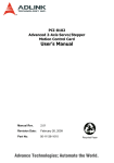
Most application programs use an incremental encoder to retrieve position feedback. A
homing operation is essential to performing accurate motion control. After the power is
switched on, the status of the machine bench's position can be in one of three
states. First, position is stopped at the homing position awaiting the next command;
second, position is stopped at the ORG sensor; third, position is stopped somewhere
between ORG and Limit Switch (PEL and MEL). Please refer to the block diagram
in Fig. 3.15 below.
1
2
3
1
M
PEL
O RG
MEL
Figure 3.15
PCI-DMC-A01 provides different functions for each of the above conditions. For homing
mode in a normal position, PCI-DMC-A01 offers up to 35 different reset to home
functions (including the reserved part). The user can simply use software settings to
have the hardware perform the user-selected homing operation. Once the homing
motion is complete, the corresponding command and feedback position will be cleared
to 0. The target position will however not be cleared to 0. The following graph shows the
conditions for executing homing:
Figure 3.16
Revised March, 2012
3-9
Chapter 3 Operating Principles | PCI-DMC-A01 / PCI-DMC-B01
3.4.2
Function List
Table 3.4
Function Name
_DMC_01_set_home_config
_DMC_01_set_home_move
_DMC_01_escape_home_move
3.4.3
Sample Application
Program Appearance
Figure 3.17
1) Open card and initialization
Click on the “Initial” button to open and initialize the card.
For a detailed description of card initialization, please refer to “Open card” and “Card
initialization” in Section 3.1.2.
3-10
Revised March, 2012
Chapter 3 Operating Principles | PCI-DMC-A01 / PCI-DMC-B01
2) Enter the values of the arguments for motion control
Figure 3.18
NodeID item: API function's argument variable “NodeID”.
Timer Checkbox: Check to display the motion status. Uncheck to disable display.
Vel. item: Number of pulses per second. API function's argument variable
“MaxVel”.
Acc. item: Time required to reach maximum velocity. API function's argument
variable “acc”.
3) Set homing parameter (Homing mode and offset)
Figure 3.19
Mode item: Homing modes 1 to 35. API function's argument variable
“home_mode”.
Offset item: Homing offsetAPI function's argument variable “home_offset”.
4) Set Servo Motor Power ON/OFF(servo on/servo off)
Figure 3.20
Click on the “SVON” button to execute the following procedure:
rt = _DMC_01_ipo_set_svon(gDMCCardNo, NodeID, SlotID , ON_OFF);
// ON_OFF: 0 – Servo Power OFF; 1 – Servo Power ON
Revised March, 2012
3-11
Chapter 3 Operating Principles | PCI-DMC-A01 / PCI-DMC-B01
5) Homing operation
See Fig. 3.20. Click on “Move” to begin executing the following procedure;
/* Set homing mode: 1~35, offset and velocity parameters */
rt = _DMC_01_set_home_config(gDMCCardNo, NodeID, SlotID, home_mode,
home_offset, StrVel, MaxVel, acc);
/* Start homing motion */
rt = _DMC_01_set_home_move(gDMCCardNo, NodeID, SlotID);
6) Stop homing motion
If you wish to stop the homing motion operation, you must hit the “STOP” button to
execute the following procedure:
/* Interrupt homing motion */
rt = _DMC_01_escape_home_move(gDMCCardNo, NodeID, SlotID);
7) Exit procedure
Click on the “Exit” button to quit and exit the procedure.
“_DMC_01_reset_card” and “_DMC_01_close” must be executed to exit this
function. Please refer to Section 3.12 “Exit procedure” for the function operations.
3-12
Revised March, 2012
Chapter 3 Operating Principles | PCI-DMC-A01 / PCI-DMC-B01
3.5
Torque Motion Control
3.5.1
Function List
Table 3.5
Function Name
_DMC_01_set_torque_mode
_DMC_01_set_torque
_DMC_01_set_torque_stop
_DMC_01_get_torque
3.5.2
Sample Application
Program Appearance
Figure 3.21
1) Card initialization
Click on the “Initial” button to open and initialize the card.
For a detailed description of card initialization, please refer to “Open card” and “Card
initialization” in Section 3.1.2.
2) Set Servo Node ID and enable motion status display
Figure 3.22
Revised March, 2012
3-13
Chapter 3 Operating Principles | PCI-DMC-A01 / PCI-DMC-B01
Input Node ID and check the “Timer” checkbox to enable motion status display
NodeID item: API function argument variable “NodeID”.
Timer Checkbox: Check to display the motion status. Uncheck to disable display.
3) Enter values for slope and ratio
Figure 3.23
Slope item: Time required to go from 0 to 100% rate torque. (Unit: ms)
Ratio item: Thousandths of rated torque. For example, a value of 100 represents
10% of rated torque.
4) Set Servo Motor Power ON/OFF(servo on/servo off)
Figure 3.24
Click on the “SVON” button to execute the following procedure:
rt = _DMC_01_ipo_set_svon (gDMCCardNo, NodeID, SlotID , ON_OFF);
// ON_OFF: 0 – Servo Power OFF; 1 – Servo Power ON
5) Torque Motion Control
Click on the “” or “” button to execute the following procedure:
/* Set torque parameter (slope value) */
rt = _DMC_01_set_torque_mode(gDMCCardNo, NodeID, SlotID, slope);
/* Start torque motion */
rt = _DMC_01_set_torque(gDMCCardNo, NodeID, SlotID, ratio);
// If ratio is greater than 0, the motor rotates clockwise. If ratio is less than 0, the
motor rotates counterclockwise.
Press the “STOP” button to execute torque stop or not
/* Whether the motor's torque motion has stopped or not depends on the Stop value.
If Stop value is 1 then torque motion has stopped. */
rt = _DMC_01_set_torque_stop(gDMCCardNo, NodeID, SlotID, stop);
6) Display current torque value
rt = _DMC_01_get_torque(gDMCCardNo, NodeID, SlotID, &torque);
// torque variable will return current torque value
3-14
Revised March, 2012
Chapter 3 Operating Principles | PCI-DMC-A01 / PCI-DMC-B01
7) Exit procedure
Click on the “Exit” button to quit and exit the procedure.
“_DMC_01_reset_card” and “_DMC_01_close” must be executed to exit this
function. Please refer to Section 3.12 “Exit procedure” for the function operations.
Revised March, 2012
3-15
Chapter 3 Operating Principles | PCI-DMC-A01 / PCI-DMC-B01
3.6
Velocity Motion Control (1)
3.6.1
Function List
Table 3.6
Function Name
_DMC_01_set_velocity_mode
_DMC_01_set_velocity
_DMC_01_set_velocity_stop
_DMC_01_get_rpm
3.6.2
Sample Application
Program Appearance
Figure 3.25
1) Card initialization
Click on the “Initial” button to open and initialize the card.
For a detailed description of card initialization, please refer to “Open card” and “Card
initialization” in Section 3.1.2.
2) Set Servo Node ID and enable motion status display
Figure 3.26
3-16
Revised March, 2012
Chapter 3 Operating Principles | PCI-DMC-A01 / PCI-DMC-B01
Input Node ID and check the “Timer” checkbox to enable motion status display
NodeID item: API function's argument variable “NodeID”.
Timer Checkbox: Check to display the motion status. Uncheck to disable display.
3) Enter the values for acceleration/deceleration time and rotations per minute (RPM)
Figure 3.27
Tacc item API function's argument variable “Tacc”.
Tdec item: API function's argument variable “Tdec”.
RPM item: API function's argument variable “rpm”.
※Actual RPM is 10% of rpm variable.
4) Set Servo Motor Power ON/OFF(servo on/servo off)
Figure 3.28
Click on the “SVON” button to execute the following procedure:
rt = _DMC_01_ipo_set_svon(gDMCCardNo, NodeID, SlotID , ON_OFF);
// ON_OFF: 0 – Servo Power OFF; 1 – Servo Power ON
5) Velocity Motion Control
Click on the “” or “” button to execute the following procedure:
/* Set velocity mode parameter (value for acceleration and deceleration time)) */
rt = _DMC_01_set_velocity_mode(gDMCCardNo, NodeID, SlotID, Tacc, Tdec);
/* Start velocity mode motion */
rt = _DMC_01_set_velocity(gDMCCardNo, NodeID, SlotID, rpm);
// If value of RPM is greater than 0 then drive motor rotates clockwise. if value is less
than 0 then rotates counterclockwise.
Press the “STOP” button to execute velocity stop or not.
/* Set whether to stop velocity motion control. If stop value is 1 then velocity motion
stops. */
rt = _DMC_01_set_velocity_stop(gDMCCardNo, NodeID, SlotID, stop);
Revised March, 2012
3-17
Chapter 3 Operating Principles | PCI-DMC-A01 / PCI-DMC-B01
6) Display current RPM value
rt = _DMC_01_get_rpm (gDMCCardNo, NodeID, SlotID, & rpm);
// Value returned by RPM variableActual motion RPM is 10% of RPM variable value
7) Exit procedure
Click on the “Exit” button to quit and exit the procedure.
“_DMC_01_reset_card” and “_DMC_01_close” must be executed to exit this
function. Please refer to Section 3.12 “Exit procedure” for the function operations.
3-18
Revised March, 2012
Chapter 3 Operating Principles | PCI-DMC-A01 / PCI-DMC-B01
3.7
Velocity Motion Control (2)
3.7.1
Function List
Table 3.7
Function Name
_DMC_01_tv_move
_DMC_01_sv_move
_DMC_01_emg_stop
3.7.2
Sample Application
Program Appearance
Figure 3.29
1) Card initialization
Click on the “Initial” button to open and initialize the card.
For a detailed description of card initialization, please refer to “Open card” and “Card
initialization” in Section 3.1.2.
2) Set Servo Node ID and enable motion status display
Figure 3.30
Input Node ID and check the “Timer” checkbox to enable motion status display
NodeID item: API function's argument variable “NodeID”.
Timer Checkbox: Check to display the motion status. Uncheck to disable display.
Revised March, 2012
3-19
Chapter 3 Operating Principles | PCI-DMC-A01 / PCI-DMC-B01
3) Enter the values of the arguments for motion control
Figure 3.31
StrVel item: Starting velocity. API function's argument variable “StrVel”.
MaxVel item: Maximum velocity. API function's argument variable “MaxVel”.
Acc. item: Time required to reach maximum velocity. API function's argument
variable “acc”.
S-Curve checkbox: You must check this box if you wish to use the S-curve velocity
curve.
4) Set Servo Motor Power ON/OFF(servo on/servo off)
Click on the “SVON” button to execute the following procedure:
rt = _DMC_01_ipo_set_svon(gDMCCardNo, NodeID, SlotID , ON_OFF);
// ON_OFF: 0 – Servo Power OFF; 1 – Servo Power ON
5) Start velocity motion control
Click on the “” or ““ button to execute the following procedure:
/* S-curve velocity curve */
rt = _DMC_01_sv_move(gDMCCardNo, NodeID, SlotID, StrVel, MaxVel, acc, 0);
/* T-curve velocity curve */
rt = _DMC_01_tv_move(gDMCCardNo, NodeID, SlotID, StrVel, MaxVel, acc, 0);
6) Stop motion
Hit the “STOP” button to execute an emergency stop:
rt = _DMC_01_emg_stop (gDMCCardNo, NodeID, SlotID);
In this example, emergency stop is used to stop motion. This method quickly stops
motion by setting deceleration time to 0. For more information about the Stop Motion
function, refer to the later section on “Stop Motion Control API”.
7) Exit procedure
Click on the “Exit” button to quit and exit the procedure.
“_DMC_01_reset_card” and “_DMC_01_close” must be executed to exit this
function. Please refer to Section 3.12 “Exit procedure” for the function operations.
3-20
Revised March, 2012
Chapter 3 Operating Principles | PCI-DMC-A01 / PCI-DMC-B01
3.8
Point to Point Motion Control
3.8.1
Overview
Point to point motion control can be used with single and multi-axes.
For single- or multi-axes point to point motion control, PCI-DMC-A01 absolute or
relative coordinate motion modes with a S-Curve or T-curve velocity cross-section.
P0
P1
Figure 3.32
Fig. 3.32 for example shows motion displacement from P0 to P1 along a single axis.
You can choose to use T-curve or S-curve motion modes based on relative or absolute
coordinates for motion displacement.
3.8.2
Function List
Table 3.8
Function Name
_DMC_01_ipo_set_svon
_DMC_01_start_tr_move
_DMC_01_start_sr_move
_DMC_01_start_ta_move
_DMC_01_start_sa_move
_DMC_01_sd_stop
_DMC_01_set_command
_DMC_01_set_position
_DMC_01_get_command
_DMC_01_get_position
_DMC_01_get_current_speed
_DMC_01_motion_status
DMC_01_motion_done
Revised March, 2012
3-21
Chapter 3 Operating Principles | PCI-DMC-A01 / PCI-DMC-B01
3.8.3
Sample Application
Program Appearance
Figure 3.33
1) Card initialization
Click on the “Initial” button to open and initialize the card.
For a detailed description of card initialization, please refer to “Open card” and “Card
initialization” in Section 3.1.2.
2) Set Servo Node ID and enable motion status display
Figure 3.34
Input Node ID and check the “Timer” checkbox to enable motion status display
NodeID item: API function's argument variable “NodeID”.
Timer Checkbox: Check to display the motion status. Uncheck to disable display.
3-22
Revised March, 2012
Chapter 3 Operating Principles | PCI-DMC-A01 / PCI-DMC-B01
3) Enter the values of the arguments for motion control
Figure 3.35
StrVel item: Starting velocity. API function's argument variable “StrVel”.
MaxVel item: Maximum velocity. API function's argument variable “MaxVel”.
Acc. item: Time required to reach maximum velocity. API function's argument
variable “acc”.
Dec item: Time required to go from maximum velocity to 0. API function's argument
variable “dec”.
4) Select motion mode and set motion distance.
Figure 3.36
Abs. Checkbox: You must check this if you want motion displacement to use
absolute coordinates.
S-Curve checkbox: You must check this box if you wish to use the S-curve velocity
curve.
Dist. item: Motion distance. API function's argument variable “Distance”.
5) Set Servo Motor Power ON/OFF(servo on/servo off)
Figure 3.37
Click on the “SVON” button to execute the following procedure:
rt = _DMC_01_ipo_set_svon(gDMCCardNo, NodeID, SlotID , ON_OFF);
// ON_OFF: 0 – Servo Power OFF; 1 – Servo Power ON
Revised March, 2012
3-23
Chapter 3 Operating Principles | PCI-DMC-A01 / PCI-DMC-B01
6) Start point to point motion control
Click on the “” or ““ button to execute the following procedure:
rt = _DMC_01_start_sa_move(gDMCCardNo, NodeID, SlotID, Distance, StrVel,
MaxVel, acc, dec);
// Motion displacement using absolute coordinates with S-curve velocity
cross-section
rt = _DMC_01_start_ta_move(gDMCCardNo, NodeID, SlotID, Distance, StrVel,
MaxVel, acc, dec);
// Motion displacement using absolute coordinates with T-curve velocity
cross-section
rt = _DMC_01_start_sr_move(gDMCCardNo, NodeID, SlotID, Distance, StrVel,
MaxVel, acc, dec);
// Motion displacement using relative coordinates with S-curve velocity cross-section
rt = _DMC_01_start_tr_move(gDMCCardNo, NodeID, SlotID, Distance, StrVel,
MaxVel, acc, dec);
// Motion displacement using relative coordinates with T-curve velocity cross-section
7) Reset motion displacement counter (Command and Feedback)
Figure 3.38
Click on the “RESET” button to execute reset command:
/* If you wish to reset the command and feedback counters, you must first set drive
motor to "servo off" */
if(gbIsSVON)
rt = _DMC_01_ipo_set_svon(gDMCCardNo, NodeID, SlotID , 0);
/* The motion counters can only be cleared when the motor is confirmed to be
"servo off" */
rt = _DMC_01_set_command(gDMCCardNo, NodeID, SlotID, 0); // Clear command
rt = _DMC_01_set_position(gDMCCardNo, NodeID, SlotID, 0); // Clear feedback
/* Once the command and feedback counters are cleared, set drive motors to "servo
on" again */
if(gbIsSVON)
rt = _DMC_01_ipo_set_svon(gDMCCardNo, NodeID, SlotID , 1);
3-24
Revised March, 2012
Chapter 3 Operating Principles | PCI-DMC-A01 / PCI-DMC-B01
Motion counter value:
rt = _DMC_01_get_command(gDMCCardNo, NodeID, SlotID, &cmd);
// Get value of command counter
rt = _DMC_01_get_position(gDMCCardNo, NodeID, SlotID, &pos);
// Get value of feedback counter
Motion status:
rt = _DMC_01_get_current_speed(gDMCCardNo, NodeID, SlotID, &speed);
// Get velocity of current motion
rt = _DMC_01_motion_status(gDMCCardNo, NodeID, SlotID, &MC_status);
// Get current status
rt = _DMC_01_motion_done(gDMCCardNo, NodeID, SlotID, &MC_done);
// Get current motor status
8) Stop motion
Figure 3.39
Hit the “STOP” button to execute an emergency stop:
rt = _DMC_01_emg_stop (gDMCCardNo, NodeID, SlotID);
In this example, emergency stop is used to stop motion. This method quickly stops
motion by setting deceleration time to 0. For more information about the Stop Motion
function, refer to the later section on “Stop Motion Control API”.
9) Exit procedure
Click on the “Exit” button to quit and exit the procedure.
“_DMC_01_reset_card” and “_DMC_01_close” must be executed to exit this
function. Please refer to Section 3.12 “Exit procedure” for the function operations.
Revised March, 2012
3-25
Chapter 3 Operating Principles | PCI-DMC-A01 / PCI-DMC-B01
3.9
Linear Interpolation Motion Control
3.9.1
Overview
If you wish to use CANopen PDO protocol for motion control you must operate in the
CANopen IP mode.
PCI-DMC-A01 supports 2~3 axis linear interpolation in absolute or relative coordinate
motion modes under the S-curve or T-curve velocity cross-section.
2-axis linear interpolation is as shown in Fig. 3.30.
This is a straight line that starts and P0 and ends at P1 in 2 dimensions.
Velocity is the vector speeds (dX:dY) along the X and Y axes as shown in Fig. 3.37:
Y
P1(X1,Y1)
dY
P0(X0,Y0)
dX
X
Figure 3.40
3.9.2
Function List
Table 3.9
Function Name
_DMC_01_start_tr_move_xy
_DMC_01_start_sr_move_xy
_DMC_01_start_ta_move_xy
_DMC_01_start_sa_move_xy
_DMC_01_start_tr_move_xyz
_DMC_01_start_sr_move_xyz
_DMC_01_start_ta_move_xyz
_DMC_01_start_sa_move_xyz
_DMC_01_sd_stop
3-26
Revised March, 2012
Chapter 3 Operating Principles | PCI-DMC-A01 / PCI-DMC-B01
3.9.3
Sample Application
Program Appearance
Figure 3.41
1) Card initialization
Click on the “Initial” button to start card initialization.
For a detailed description of card initialization, please refer to Section 3.1.2 - 1)
Open card.
2) Get Slot ID and enable motion status display
Figure 3.42
Check the “Timer” checkbox to enable motion status display
Timer Checkbox: Check to display the motion status. Uncheck to disable display.
Revised March, 2012
3-27
Chapter 3 Operating Principles | PCI-DMC-A01 / PCI-DMC-B01
3) Enter the values of the arguments for motion control
Figure 3.43
StrVel item: Starting velocity. API function's argument variable “StrVel”.
MaxVel item: Maximum velocity. API function's argument variable “MaxVel”.
Acc. item: Time required to reach maximum velocity. API function's argument
variable “acc”.
Dec item: Time required to go from maximum velocity to 0. API function's argument
variable “dec”.
4) Select motion mode and set motion distance.
Figure 3.44
Abs. Checkbox: You must check this if you want motion displacement to use
absolute coordinates.
S-Curve checkbox: You must check this box if you wish to use the S-curve velocity
curve.
Dist. item: Motion distance. API function's argument variable “Distance”.
5) Set Servo Motor Power ON/OFF(servo on/servo off)
Figure 3.45
Click on the “SVON” button to execute the following procedure:
rt = _DMC_01_ipo_set_svon(gDMCCardNo, NodeID, SlotID , ON_OFF);
// ON_OFF: 0 – Servo Power OFF; 1 – Servo Power ON
3-28
Revised March, 2012
Chapter 3 Operating Principles | PCI-DMC-A01 / PCI-DMC-B01
6) Start motion control with linear interpolation in 2 or 3 axes
Click on the “” or ““ button to execute the following procedure:
2-axis linear interpolation:
rt = _DMC_01_start_sa_move_xy(gDMCCardNo, gLine2, gSlot2, Distance,
Distance, StrVel, MaxVel, acc, dec);
//// Linear interpolation motion using absolute coordinates with S-curve velocity
cross-section
rt = _DMC_01_start_ta_move_xy(gDMCCardNo, gLine2, gSlot2, Distance,
Distance, StrVel, MaxVel, acc, dec); //// Linear interpolation motion using absolute
coordinates with T-curve velocity cross-section
rt = _DMC_01_start_sr_move_xy(gDMCCardNo, gLine2, gSlot2, Distance,
Distance, StrVel, MaxVel, acc, dec);
//// Linear interpolation motion using relative coordinates with S-curve velocity
cross-section
rt = _DMC_01_start_tr_move_xy(gDMCCardNo, gLine2, gSlot2, Distance, Distance,
StrVel, MaxVel, acc, dec); //// Linear interpolation motion using relative coordinates
with T-curve velocity cross-section
3-axis linear interpolation:
rt = _DMC_01_start_sa_move_xyz(gDMCCardNo, gLine3, gSlot3, Distance,
Distance, Distance, StrVel, MaxVel, acc, dec);
//// Linear interpolation motion using absolute coordinates with S-curve velocity
cross-section
rt = _DMC_01_start_ta_move_xyz(gDMCCardNo, gLine3, gSlot3, Distance,
Distance, Distance, StrVel, MaxVel, acc, dec);
//// Linear interpolation motion using absolute coordinates with T-curve velocity
cross-section
rt = _DMC_01_start_sr_move_xyz(gDMCCardNo, gLine3, gSlot3, Distance,
Distance, Distance, StrVel, MaxVel, acc, dec);
//// Linear interpolation motion using relative coordinates with S-curve velocity
cross-section
rt = _DMC_01_start_tr_move_xyz(gDMCCardNo, gLine3, gSlot3, Distance,
Distance, Distance, StrVel, MaxVel, acc, dec);
//// Linear interpolation motion using relative coordinates with T-curve velocity
cross-section
Revised March, 2012
3-29
Chapter 3 Operating Principles | PCI-DMC-A01 / PCI-DMC-B01
7) Stop motion
Figure 3.46
Hit the “STOP” button to execute an emergency stop:
rt = _DMC_01_emg_stop (gDMCCardNo, NodeID, SlotID);
In this example, emergency stop is used to stop motion. This method quickly stops
motion by setting deceleration time to 0. For more information about the Stop Motion
function, refer to the later section on “Stop Motion Control API”.
8) Exit procedure
Click on the “Exit” button to quit and exit the procedure.
“_DMC_01_reset_card” and “_DMC_01_close” must be executed to exit this
function. Please refer to Section 3.12 “Exit procedure” for the function operations.
3-30
Revised March, 2012
Chapter 3 Operating Principles | PCI-DMC-A01 / PCI-DMC-B01
3.10 Arc Interpolation Motion Control
3.10.1
Overview
PCI-DMC-A01 supports 2-axis arc interpolation in absolute or relative coordinate
motion modes under the S-curve or T-curve velocity cross-section. Fig. 3.44 illustrates
arc interpolation on any 2 axes.
The start point is P0 (X0, Y0) and end point is P1(X1, Y1). The path from P0 to P1
forms an arc. The maximum velocity is the tangential velocity.
P0
Cent
P1
Figure 3.47
3.10.2
Function List
Table 3.10
Function Name
_DMC_01_start_tr_arc_xy
_DMC_01_start_sr_arc_xy
_DMC_01_start_ta_arc_xy
_DMC_01_start_sa_arc_xy
_DMC_01_start_tr_arc2_xy
_DMC_01_start_sr_arc2_xy
_DMC_01_start_ta_arc2_xy
_DMC_01_start_sa_arc2_xy
_DMC_01_start_tr_arc3_xy
_DMC_01_start_sr_arc3_xy
_DMC_01_start_ta_arc3_xy
_DMC_01_start_sa_arc3_xy
Revised March, 2012
3-31
Chapter 3 Operating Principles | PCI-DMC-A01 / PCI-DMC-B01
3.10.3
Sample Application
Program Appearance
Figure 3.48
1) Card initialization
Click on the “Initial” button to open and initialize the card.
For a detailed description of card initialization, please refer to “Open card” and “Card
initialization” in Section 3.1.2.
2) Get Slot ID and enable motion status display
Figure 3.49
Check the “Timer” checkbox to enable motion status display
Timer Checkbox: Check to display the motion status. Uncheck to disable display.
3) Enter the values of the arguments for motion control
Figure 3.50
3-32
Revised March, 2012
Chapter 3 Operating Principles | PCI-DMC-A01 / PCI-DMC-B01
StrVel item: Starting velocity. API function's argument variable “StrVel”.
MaxVel item: Maximum velocity. API function's argument variable “MaxVel”.
Acc. item: Time required to reach maximum velocity. API function's argument
variable “acc”.
Dec item: Time required to go from maximum velocity to 0. API function's argument
variable “dec”.
Abs. Checkbox: You must check this if you want motion displacement to use
absolute coordinates.
S-Curve checkbox: You must check this box if you wish to use the S-curve velocity
curve.
4) Select the type of 2-axis arc interpolation and enter the corresponding values
➊
➋
➌
Figure 3.51
Arc 1: Interpolation method 1. Must provide the center coordinates (X, Y) and angle
(0o to 359o)
➊ Cen_X item: Center's x-coordinate. API function's argument variable
“arc1_cen_x”.
Cen_Y item: Center's y-coordinate. API function's argument variable
“arc1_cen_y”.
Angle item: Angle. API function's argument variable “arc1_angle”.
Arc 2: Interpolation method 2. Must enter the endpoint coordinates (X, Y) and angle
(0o to 359o)
➋ End_X item: Endpoint's x-coordinate. API function's argument variable
“arc2_end_x”.
End_Y item: Endpoint's Y-coordinate. API function's argument variable
“arc2_end_y”.
Angle item: Angle. API function's argument variable “arc2_angle”.
Arc 3: Interpolation method 3. Must provide the center coordinates (X, Y), endpoint
coordinates (X, Y) and direction.
Revised March, 2012
3-33
Chapter 3 Operating Principles | PCI-DMC-A01 / PCI-DMC-B01
➌ Cen_X item: Center's x-coordinate. API function's argument variable
“arc3_cen_x”.
Cen_Y item: Center's y-coordinate. API function's argument variable
“arc3_cen_y”.
End_X item: Endpoint's x-coordinate. API function's argument variable
“arc3_end_x”.
End_Y item: Endpoint's Y-coordinate. API function's argument variable
“arc3_end_y”.
Dir item: Direction. API function's argument variable “arc3_dir”.
When this value is 0, the servo motor will rotate clockwise (CW).
When this value is 1, the servo motor will counterclockwise (CCW).
5) Set Servo Motor Power ON/OFF(servo on/servo off)
Figure 3.52
Click on the “SVON” button to execute the following procedure:
rt = _DMC_01_ipo_set_svon(gDMCCardNo, NodeID, SlotID , ON_OFF);
// ON_OFF: 0 – Servo Power OFF; 1 – Servo Power ON
6) Start 2-axis arc interpolation motion control
Click on the “” or ““ button to execute the following procedure:
2-axis arc interpolation using interpolation method 1 (Arc1):
rt = _DMC_01_start_sa_arc_xy(gDMCCardNo, gArcNode, gSlot2, arc1_cen_x,
arc1_cen_y, arc1_angle, StrVel, MaxVel, acc, dec);
// Arc interpolation motion using absolute coordinates under the S-curve velocity
cross-section
rt = _DMC_01_start_ta_arc_xy(gDMCCardNo, gArcNode, gSlot2, arc1_cen_x,
arc1_cen_y, arc1_angle, StrVel, MaxVel, acc, dec);
// Arc interpolation motion using absolute coordinates under the T-curve velocity
cross-section
rt = _DMC_01_start_sr_arc_xy(gDMCCardNo, gArcNode, gSlot2, arc1_cen_x,
arc1_cen_y, arc1_angle, StrVel, MaxVel, acc, dec);
// Arc interpolation motion using relative coordinates under the S-curve velocity
cross-section
rt = _DMC_01_start_tr_arc_xy(gDMCCardNo, gArcNode, gSlot2, arc1_cen_x,
arc1_cen_y, arc1_angle, StrVel, MaxVel, acc, dec);
// Arc interpolation motion using relative coordinates under the T-curve velocity
cross-section
3-34
Revised March, 2012
Chapter 3 Operating Principles | PCI-DMC-A01 / PCI-DMC-B01
2-axis arc interpolation using interpolation method 2 (Arc2).
rt = _DMC_01_start_sa_arc2_xy(gDMCCardNo, gArcNode, gSlot2, arc2_end_x,
arc2_end_y, arc2_angle, StrVel, MaxVel, acc, dec);
// Arc interpolation motion using absolute coordinates under the S-curve velocity
cross-section
rt = _DMC_01_start_ta_arc2_xy(gDMCCardNo, gArcNode, gSlot2, arc2_end_x,
arc2_end_y, arc2_angle, StrVel, MaxVel, acc, dec);
// Arc interpolation motion using absolute coordinates under the T-curve velocity
cross-section
rt = _DMC_01_start_sr_arc2_xy(gDMCCardNo, gArcNode, gSlot2, arc2_end_x,
arc2_end_y, arc2_angle, StrVel, MaxVel, acc, dec);
// Arc interpolation motion using relative coordinates under the S-curve velocity
cross-section
rt = _DMC_01_start_tr_arc2_xy(gDMCCardNo, gArcNode, gSlot2, arc2_end_x,
arc2_end_y, arc2_angle, StrVel, MaxVel, acc, dec);
// Arc interpolation motion using relative coordinates under the T-curve velocity
cross-section
2-axis arc interpolation using interpolation method 3 (Arc3):
rt = _DMC_01_start_sa_arc3_xy(gDMCCardNo, gArcNode, gSlot2, arc3_cen_x,
arc3_cen_y, arc3_end_x, arc3_end_y, arc3_dir, StrVel, MaxVel, acc, dec);
// Arc interpolation motion using absolute coordinates under the S-curve velocity
cross-section
rt = _DMC_01_start_ta_arc3_xy(gDMCCardNo, gArcNode, gSlot2, arc3_cen_x,
arc3_cen_y, arc3_end_x, arc3_end_y, arc3_dir, StrVel, MaxVel, acc, dec);
// Arc interpolation motion using absolute coordinates under the T-curve velocity
cross-section
rt = _DMC_01_start_sr_arc3_xy(gDMCCardNo, gArcNode, gSlot2, arc3_cen_x,
arc3_cen_y, arc3_end_x, arc3_end_y, arc3_dir, StrVel, MaxVel, acc, dec);
// Arc interpolation motion using relative coordinates under the S-curve velocity
cross-section
rt = _DMC_01_start_tr_arc3_xy(gDMCCardNo, gArcNode, gSlot2, arc3_cen_x,
arc3_cen_y, arc3_end_x, arc3_end_y, arc3_dir, StrVel, MaxVel, acc, dec);
// Arc interpolation motion using relative coordinates under the T-curve velocity
cross-section
7) Stop motion
Figure 3.53
Revised March, 2012
3-35
Chapter 3 Operating Principles | PCI-DMC-A01 / PCI-DMC-B01
Hit the “STOP” button to execute an emergency stop:
rt = _DMC_01_emg_stop (gDMCCardNo, NodeID, SlotID);
In this example, emergency stop is used to stop motion. This method quickly stops
motion by setting deceleration time to 0. For more information about the Stop Motion
function, refer to the later section on “Stop Motion Control API”.
8) Exit procedure
Click on the “Exit” button to quit and exit the procedure.
“_DMC_01_reset_card” and “_DMC_01_close” must be executed to exit this
function. Please refer to Section 3.12 “Exit procedure” for the function operations.
3-36
Revised March, 2012
Chapter 3 Operating Principles | PCI-DMC-A01 / PCI-DMC-B01
3.11 Spiral Interpolation Motion Control -Helix
3.11.1
Function List
Table 3.11
Function Name
_DMC_01_start_tr_heli_xy
_DMC_01_start_sr_heli_xy
_DMC_01_start_ta_heli_xy
_DMC_01_start_sa_heli_xy
3.11.2
Sample Application
Program Appearance
Figure 3.54
Revised March, 2012
3-37
Chapter 3 Operating Principles | PCI-DMC-A01 / PCI-DMC-B01
1) Card initialization
Click on the “Initial” button to open and initialize the card.
For a detailed description of card initialization, please refer to “Open card” and “Card
initialization” in Section 3.1.2.
2) Get Slot ID and enable motion status display
Figure 3.55
Check the “Timer” checkbox to enable motion status display
Timer Checkbox: Check to display the motion status. Uncheck to disable display.
Below motion status is the “RESET” button. Click on the “RESET” button to execute
the reset command.
/* If you wish to reset the command and feedback counters, you must first set drive
motor to "servo off" */
if(gbIsSVON)
rt = _DMC_01_ipo_set_svon(gDMCCardNo, NodeID, SlotID , 0);
/* The motion counters can only be cleared when the motor is confirmed to be
"servo off" */
rt = _DMC_01_set_command(gDMCCardNo, NodeID, SlotID, 0); // Clear command
rt = _DMC_01_set_position(gDMCCardNo, NodeID, SlotID, 0); // Clear feedback
/* Once the command and feedback counters are cleared, set drive motors to "servo
on" again */
if(gbIsSVON)
rt = _DMC_01_ipo_set_svon(gDMCCardNo, NodeID, SlotID , 1);
Motion counter value:
rt = _DMC_01_get_command(gDMCCardNo, NodeID, SlotID, &cmd);
// Get value of command counter
rt = _DMC_01_get_position(gDMCCardNo, NodeID, SlotID, &pos);
// Get value of feedback counter
Motion status:
rt = _DMC_01_get_current_speed(gDMCCardNo, NodeID, SlotID, &speed);
// Get velocity of current motion
3-38
Revised March, 2012
Chapter 3 Operating Principles | PCI-DMC-A01 / PCI-DMC-B01
rt = _DMC_01_motion_status(gDMCCardNo, NodeID, SlotID, &MC_status);
// Get current status
rt = _DMC_01_motion_done(gDMCCardNo, NodeID, SlotID, &MC_done);
// Get current motor status
3) Enter the argument values and chosen velocity cross-section for motion control
Figure 3.56
StrVel item: Starting velocity. API function's argument variable “StrVel”.
MaxVel item: Maximum velocity. API function's argument variable “MaxVel”.
Acc. item: Time required to reach maximum velocity. API function's argument
variable “acc”.
Dec item: Time required to go from maximum velocity to 0. API function's argument
variable “dec”.
Cen_X item: Center's x-coordinate. API function's argument variable “helix_cen_x”.
Cen_Y item: Center's y-coordinate. API function's argument variable “helix_cen_y”.
Depth item: Total distance of 3rd axis. (See Fig. 3.55).
Pitch item: Distance in the 3rd axis when one revolution is completed in axis-1 and
axis-2.
Dir item: The direction of the arc path in axis-1 and axis-2 (0: Clockwise; 1:
Counterclockwise).
Abs. Checkbox: You must check this if you want motion displacement to use
absolute coordinates.
S-Curve checkbox: You must check this box if you wish to use the S-curve velocity
curve.
Revised March, 2012
3-39
Chapter 3 Operating Principles | PCI-DMC-A01 / PCI-DMC-B01
Figure 3.57
4) Set Servo Motor Power ON/OFF(servo on/servo off)
Figure 3.58
Click on the “SVON” button to execute the following procedure:
rt = _DMC_01_ipo_set_svon(gDMCCardNo, NodeID, SlotID , ON_OFF);
// ON_OFF: 0 – Servo Power OFF; 1 – Servo Power ON
5) Start spiral interpolation motion control
Click on the “” or ““ button to execute the following procedure:
rt = _DMC_01_start_sa_heli_xy(gDMCCardNo, gHelix, gSlot3, helix_cen_x,
helix_cen_y, helix_depth, helix_pitch, helix_dir, StrVel, MaxVel, acc, dec);
//// Spiral interpolation motion using absolute coordinates with S-curve velocity
cross-section
rt = _DMC_01_start_ta_heli_xy(gDMCCardNo, gHelix, gSlot3, helix_cen_x,
helix_cen_y, helix_depth, helix_pitch, helix_dir, StrVel, MaxVel, acc, dec);
//// Spiral interpolation motion using absolute coordinates with T-curve velocity
cross-section
rt = _DMC_01_start_sr_heli_xy(gDMCCardNo, gHelix, gSlot3, helix_cen_x,
helix_cen_y, helix_depth, helix_pitch, helix_dir, StrVel, MaxVel, acc, dec);
//// Spiral interpolation motion using relative coordinates with S-curve velocity
cross-section
rt = _DMC_01_start_tr_heli_xy(gDMCCardNo, gHelix, gSlot3, helix_cen_x,
helix_cen_y, helix_depth, helix_pitch, helix_dir, StrVel, MaxVel, acc, dec);
//// Spiral interpolation motion using relative coordinates with T-curve velocity
cross-section
3-40
Revised March, 2012
Chapter 3 Operating Principles | PCI-DMC-A01 / PCI-DMC-B01
6) Stop motion
Hit the “STOP” button to execute an emergency stop:
rt = _DMC_01_emg_stop (gDMCCardNo, NodeID, SlotID);
In this example, emergency stop is used to stop motion. This method quickly stops
motion by setting deceleration time to 0. For more information about the Stop Motion
function, refer to the later section on “Stop Motion Control API”.
7) Exit procedure
Click on the “Exit” button to quit and exit the procedure.
“_DMC_01_reset_card” and “_DMC_01_close” must be executed to exit this
function. Please refer to Section 3.12 “Exit procedure” for the function operations.
Revised March, 2012
3-41
Chapter 3 Operating Principles | PCI-DMC-A01 / PCI-DMC-B01
3.12 Continuous Interpolation Motion Control
3.12.1
Overview
A series of motion commands can be used to describe a square path with rounded
corners.
PCI-DMC-A01 supports using the 20-unit software FIFO in Motion ASIC for motion
control during continuous interpolation. Please refer to the following diagram:
System
Command
Motor
Program
Read
Displacement
Get buffer
FIFO
FIFO
FIFO
Execute FIFO
length
No 19
No 18
No 1
No 0
Figure 3.59
3.12.2
Function List
Table 3.12
Function Name
_DMC_01_start_ta_move_xy
_DMC_01_start_ta_arc_xy
3-42
Revised March, 2012
Chapter 3 Operating Principles | PCI-DMC-A01 / PCI-DMC-B01
3.12.3
Sample Application
If you wish to perform the continuous interpolation motion illustrated below, you must
execute the following procedure and carry out the commands from ➀ ~ ➇:
Figure 3.60
Program Appearance
Figure 3.61
Revised March, 2012
3-43
Chapter 3 Operating Principles | PCI-DMC-A01 / PCI-DMC-B01
1) Card initialization
Click on the “Initial” button to open and initialize the card.
For a detailed description of card initialization, please refer to “Open card” and “Card
initialization” in Section 3.1.2.
2) Get Slot ID and enable motion status display
Figure 3.62
Check the “Timer” checkbox to enable motion status display
Timer Checkbox: Check to display the motion status. Uncheck to disable display.
3) Enter the values of the arguments for motion control
Figure 3.63
StrVel item: Starting velocity. API function's argument variable “StrVel”.
MaxVel item: Maximum velocity. API function's argument variable “MaxVel”.
Acc. item: Time required to reach maximum velocity. API function's argument
variable “acc”.
Dec item: Time required to go from maximum velocity to 0. API function's argument
variable “dec”.
4) Enter edge length and corner radius
Figure 3.64
Edge item: Edge length (Unit: Pulses), API function's argument variable “edge”.
Radius item: Corner radius (Unit: Pulses), API function's argument variable
“radius”.
3-44
Revised March, 2012
Chapter 3 Operating Principles | PCI-DMC-A01 / PCI-DMC-B01
5) Set Servo Motor Power ON/OFF(servo on/servo off)
Figure 3.65
Click on the “SVON” button to execute the following procedure:
rt = _DMC_01_ipo_set_svon(gDMCCardNo, NodeID, SlotID , ON_OFF);
// ON_OFF: 0 – Servo Power OFF; 1 – Servo Power ON
6) Click on the “Move” button to start executing continuous interpolation motion
The following procedures ➀~➇ will realize the continuous interpolation motion
shown in Fig. 3.60. t
➀ rt = _DMC_01_start_ta_move_xy(gDMCCardNo, gLine2, gSlot2, 0, edge, 0,
radius, 0.1, 0); // Deceleration set to 0
➁ rt = _DMC_01_start_ta_arc_xy(gDMCCardNo, gLine2, gSlot2, radius, edge, 90,
0, radius, 0, 0); // Acceleration and deceleration set to 0
➂ rt = _DMC_01_start_ta_move_xy(gDMCCardNo, gLine2, gSlot2, edge + radius,
edge + radius, 0, radius, 0, 0); // Acceleration and deceleration set to 0
➃ rt = _DMC_01_start_ta_arc_xy(gDMCCardNo, gLine2, gSlot2, edge + radius,
edge, 90, 0, radius, 0, 0); // Acceleration and deceleration set to 0
➄ rt = _DMC_01_start_ta_move_xy(gDMCCardNo, gLine2, gSlot2, edge +
radius*2, 0, 0, radius, 0, 0); // Acceleration and deceleration set to 0
➅ rt = _DMC_01_start_ta_arc_xy(gDMCCardNo, gLine2, gSlot2, edge + radius, 0,
90, 0, radius, 0, 0); // Acceleration and deceleration set to 0.
➆ rt = _DMC_01_start_ta_move_xy(gDMCCardNo, gLine2, gSlot2, radius, 0 radius, 0, radius, 0, 0); // Acceleration and deceleration set to 0
➇ rt = _DMC_01_start_ta_arc_xy(gDMCCardNo, gLine2, gSlot2, radius, 0, 90, 0,
radius, 0, 0.1); // Acceleration set to 0
Revised March, 2012
3-45
Chapter 3 Operating Principles | PCI-DMC-A01 / PCI-DMC-B01
V-T diagram of actual X-axis motion:
Figure 3.66
7) Stop motion
Hit the “STOP” button to execute an emergency stop:
rt = _DMC_01_emg_stop (gDMCCardNo, NodeID, SlotID);
In this example, emergency stop is used to stop motion. This method quickly stops
motion by setting deceleration time to 0. For more information about the Stop Motion
function, refer to the later section on “Stop Motion Control API”.
8) Exit procedure
Click on the “Exit” button to quit and exit the procedure.
“_DMC_01_reset_card” and “_DMC_01_close” must be executed to exit this
function. Please refer to Section 3.12 “Exit procedure” for the function operations.
3-46
Revised March, 2012
Chapter 3 Operating Principles | PCI-DMC-A01 / PCI-DMC-B01
3.13 Software Limit Control
3.13.1
Function List
Table 3.13
Function Name
_DMC_01_start_sr_move
_DMC_01_start_tr_move
_DMC_01_start_sa_move
_DMC_01_start_ta_move
_DMC_01_set_soft_limit
_DMC_01_enable_soft_limit
_DMC_01_disable_soft_limit
_DMC_01_get_soft_limit_status
3.13.2
Sample Application
Program Appearance
Figure 3.67
Revised March, 2012
3-47
Chapter 3 Operating Principles | PCI-DMC-A01 / PCI-DMC-B01
1) Card initialization
Click on the “Initial” button to start card initialization.
For a detailed description of card initialization, please refer to Section 3.1.2 - 1)
Open card.
2) Set Servo Node ID and enable motion status display
Figure 3.68
Input Node ID and check “Timer” checkbox to enable motion status display
NodeID item: API function's argument variable “NodeID”.
Timer Checkbox: Check to display the motion status. Uncheck to disable display.
3) Enter the values of the arguments for motion control
Figure 3.69
StrVel item: Starting velocity. API function's argument variable “StrVel”.
MaxVel item: Maximum velocity. API function's argument variable “MaxVel”.
Acc. item: Time required to reach maximum velocity. API function's argument
variable “acc”.
Dec item: Time required to go from maximum velocity to 0. API function's argument
variable “dec”.
4) Select motion mode and set motion distance.
Figure 3.70
Abs. Checkbox: You must check this if you want motion displacement to use
absolute coordinates.
S-Curve checkbox: You must check this box if you wish to use the S-curve velocity
curve.
Dist. item: Motion distance. API function's argument variable “Distance”.
3-48
Revised March, 2012
Chapter 3 Operating Principles | PCI-DMC-A01 / PCI-DMC-B01
5) Set positive/negative value limit, stop motion mode, and whether software limit is
enabled
Figure 3.71
N-Limit item: Value of negative limit. API function's argument variable “NLimit”.
P-Limit item: Value of positive limit. API function's argument variable “PLimit”.
Stop mode pull-down menu: Stop mode. API function's argument variable
“action”.
Soft-limit Checkbox: Enables/disables software limit.
6) If software limit is enabled, you must check the “Soft-limit Enable” checkbox and
execute the following procedure:
/* Start software limit configuration */
rt = _DMC_01_enable_soft_limit(gDMCCardNo, NodeID, SlotID, action);
// action argument specifies the stop mode to use when limit is reached. A value of 1
means an emergency stop; A value of 2 means a slow down stop.
/* Set the values for positive and negatives */
rt = _DMC_01_set_soft_limit(gDMCCardNo, NodeID, SlotID, PLimit, NLimit);
// PLimit argument is the set value for positive limit; NLimit is the set value for
negative limit
7) To disable software limit, you must use the following procedure:
rt = _DMC_01_disable_soft_limit(gDMCCardNo, NodeID, SlotID);
8) Set Servo Motor Power ON/OFF(servo on/servo off)
Figure 3.72
Click on the “SVON” button to execute the following procedure:
rt = _DMC_01_ipo_set_svon(gDMCCardNo, NodeID, SlotID , ON_OFF);
// ON_OFF: 0 – Servo Power OFF; 1 – Servo Power ON
Revised March, 2012
3-49
Chapter 3 Operating Principles | PCI-DMC-A01 / PCI-DMC-B01
9) Start motion control (Using point to point motion control as an example)
Click on the “” or “” button to execute the following procedure:
rt = _DMC_01_start_sa_move(gDMCCardNo, NodeID, SlotID, Distance, StrVel,
MaxVel, acc, dec); // Motion displacement using absolute coordinates with S-curve
velocity cross-section
rt = _DMC_01_start_ta_move(gDMCCardNo, NodeID, SlotID, Distance, StrVel,
MaxVel, acc, dec); // Motion displacement using absolute coordinates with T-curve
velocity cross-section
rt = _DMC_01_start_sr_move(gDMCCardNo, NodeID, SlotID, Distance, StrVel,
MaxVel, acc, dec); // Motion displacement using relative coordinates with S-curve
velocity cross-section
rt = _DMC_01_start_tr_move(gDMCCardNo, NodeID, SlotID, Distance, StrVel,
MaxVel, acc, dec); // Motion displacement using relative coordinates with T-curve
velocity cross-section
10) If you wish to observe the contact with positive/negative limits during point to point
motion control, you can execute the following procedure:
/* Observe feedback status from contact with positive/negative limits*/
rt = _DMC_01_get_soft_limit_status(gDMCCardNo, NodeID, SlotID, &PLimit_sts,
&NLimit_sts);
In the figure below, the left side indicates no contact with positive/negative limits
during motion; the center indicates contact with positive limit during motion; the right
side indicates contact with negative limit during motion.
Figure 3.73
11) Stop motion
Hit the “STOP” button to execute an emergency stop:
rt = _DMC_01_emg_stop (gDMCCardNo, NodeID, SlotID);
In this example, emergency stop is used to stop motion. This method quickly stops
motion by setting deceleration time to 0. For more information about the Stop Motion
function, refer to the later section on “Stop Motion Control API”.
12) Exit procedure
Click on the “Exit” button to quit and exit the procedure.
“_DMC_01_reset_card” and “_DMC_01_close” must be executed to exit this
function. Please refer to Section 3.12 “Exit procedure” for the function operations.
3-50
Revised March, 2012
Chapter 3 Operating Principles | PCI-DMC-A01 / PCI-DMC-B01
3.14 Synchronization Motion Control
3.14.1
Function List
Table 3.14
Function Name
_DMC_01_sync_move
_DMC_01_sync_move_config
3.14.2
Sample Application
Program Appearance
Figure 3.74
1) Card initialization
Click on the “Initial” button to open and initialize the card.
For a detailed description of card initialization, please refer to “Open card” and “Card
initialization” in Section 3.1.2.
Revised March, 2012
3-51
Chapter 3 Operating Principles | PCI-DMC-A01 / PCI-DMC-B01
2) Choose whether to enable synchronization motion control
Figure 3.75
Sync. Enable checkbox: Enable motor sync or not.
You can execute the following procedure to enable sync motion:
rt = _DMC_01_sync_move_config(gDMCCardNo, gpNodeID[i], SlotID, enable);
// If enable argument is 1, then synchronized motion control is enabled.
3) Set Servo Node ID and enable motion status display
Figure 3.76
Input Node ID and check “Timer” checkbox to enable motion status display
NodeID item: API function's argument variable “NodeID”.
Timer Checkbox: Check to display the motion status. Uncheck to disable display.
4) Enter the values of the arguments for motion control
Figure 3.77
StrVel item: Starting velocity. API function's argument variable “StrVel”.
MaxVel item: Maximum velocity. API function's argument variable “MaxVel”.
Acc. item: Time required to reach maximum velocity. API function's argument
variable “acc”.
Dec item: Time required to go from maximum velocity to 0. API function's argument
variable “dec”.
3-52
Revised March, 2012
Chapter 3 Operating Principles | PCI-DMC-A01 / PCI-DMC-B01
5) Select motion mode and set motion distance.
Figure 3.78
Abs. Checkbox: You must check this if you want motion displacement to use
absolute coordinates.
S-Curve checkbox: You must check this box if you wish to use the S-curve velocity
curve.
Dist. item: Motion distance. API function's argument variable “Distance”.
6) Set Servo Motor Power ON/OFF(servo on/servo off)
Click on the “SVON” button to execute the following procedure:
rt = _DMC_01_ipo_set_svon(gDMCCardNo, NodeID, SlotID , ON_OFF);
// ON_OFF: 0 – Servo Power OFF; 1 – Servo Power ON.
7) Click on the “” or ““ button to execute point to point single-axis motion command.
As you have only set up motion in one axis, this motion will not be executed right
away. You must go back to 3) Set Servo Node ID to set the motion commands for
other axes first. Once the setting have been completed, click on the “Syn. Move”
button to execute synchronized motion control command.
Figure 3.79
The synchronized motion control command is executed as shown in the following
function:
rt = _DMC_01_sync_move(gDMCCardNo);
// After synchronized motion control is complete, the synchronized motion control
setting will be disabled. If you wish to use the synchronized motion control
command again, you must re-enable synchronized motion control.
Revised March, 2012
3-53
Chapter 3 Operating Principles | PCI-DMC-A01 / PCI-DMC-B01
8) Stop motion
Hit the “STOP” button to execute an emergency stop:
rt = _DMC_01_emg_stop (gDMCCardNo, NodeID, SlotID);
In this example, emergency stop is used to stop motion. This method quickly stops
motion by setting deceleration time to 0. For more information about the Stop Motion
function, refer to the later section on “Stop Motion Control API”.
9) Exit procedure
Click on the “Exit” button to quit and exit the procedure.
“_DMC_01_reset_card” and “_DMC_01_close” must be executed to exit this
function. Please refer to Section 3.12 “Exit procedure” for the function operations.
3-54
Revised March, 2012
Chapter 3 Operating Principles | PCI-DMC-A01 / PCI-DMC-B01
3.15 Dwell Command
3.15.1
Function List
Table 3.15
Function Name
_DMC_01_start_ta_move
_DMC_01_buf_dwell
3.15.2
Sample Application
Program Appearance
Figure 3.80
1) Card initialization
Click on the “Initial” button to open and initialize the card.
For a detailed description of card initialization, please refer to “Open card” and “Card
initialization” in Section 3.1.2.
2) Set Servo Node ID and enable motion status display
Figure 3.81
NodeID item: API function's argument variable “NodeID”.
SlotID item: API function's argument variable “slotID”.
Dwell cnt. item: Enter the delay time (Mini Sec) between the execution of two API
functions.
Revised March, 2012
3-55
Chapter 3 Operating Principles | PCI-DMC-A01 / PCI-DMC-B01
3) In the following example, adding the dwell command between continuous motion
commands will ensure the execution of continuous motion:
rt = _DMC_01_start_ta_move(gDMCCardNo, NodeID, SlotID, Distance, StrVel,
MaxVel, acc, dec); // Motion displacement using absolute coordinates with T-curve
velocity cross-section
rt = _DMC_01_buf_dwell(CardNo, NodeID, SlotID, dwell_cnt);
//Set the dwell buffer interval. If dwell_cnt is 0 the delay is 4ms; In this example, the
value is 3
so delay is 2*3+2=8ms
rt = _DMC_01_start_ta_move(gDMCCardNo, NodeID, SlotID, Distance, StrVel,
MaxVel, acc, dec); // Motion displacement using absolute coordinates with T-curve
velocity cross-section
4) Set Servo Motor Power ON/OFF(servo on/servo off)
Figure 3.82
Click on the “SVON” button to execute the following procedure:
rt = _DMC_01_ipo_set_svon(gDMCCardNo, NodeID, SlotID , ON_OFF);
// ON_OFF: 0 – Servo Power OFF; 1 – Servo Power ON
5) Start motion control (Using point to point motion control as an example)
Click on the “Move” button to execute the following procedure:
rt = _DMC_01_start_ta_move(gDMCCardNo, NodeID, SlotID, Distance, StrVel,
MaxVel, acc, dec); // Motion displacement using absolute coordinates with T-curve
velocity cross-section
6) Stop motion
Hit the “STOP” button to execute an emergency stop:
rt = _DMC_01_emg_stop (gDMCCardNo, NodeID, SlotID);
In this example, emergency stop is used to stop motion. This method quickly stops
motion by setting deceleration time to 0. For more information about the Stop Motion
function, refer to the later section on “Stop Motion Control API”.
7) Exit procedure
Click on the “Exit” button to quit and exit the procedure.
“_DMC_01_reset_card” and “_DMC_01_close” must be executed to exit this
function. Please refer to Section 3.12 “Exit procedure” for the function operations.
3-56
Revised March, 2012
Chapter 3 Operating Principles | PCI-DMC-A01 / PCI-DMC-B01
3.16 Change Position
3.16.1
Function List
Table 3.16
Function Name
_DMC_01_start_ta_move
_DMC_01_p_change
3.16.2
Sample Application
Program Appearance
Figure 3.83
1) Card initialization
Click on the “Initial” button to open and initialize the card.
For a detailed description of card initialization, please refer to “Open card” and “Card
initialization” in Section 3.1.2.
2) Set Servo Node ID and enable motion status display
Figure 3.84
Revised March, 2012
3-57
Chapter 3 Operating Principles | PCI-DMC-A01 / PCI-DMC-B01
Input Node ID and check “Timer” checkbox to enable motion status display
NodeID item: API function's argument variable “NodeID”.
Timer Checkbox: Check to display the motion status. Uncheck to disable display.
3) Enter the values of the arguments for motion control
Figure 3.85
StrVel item: Starting velocity. API function's argument variable “StrVel”.
MaxVel item: Maximum velocity. API function's argument variable “MaxVel”.
Acc. item: Time required to reach maximum velocity. API function's argument
variable “acc”.
Dec item: Time required to go from maximum velocity to 0. API function's argument
variable “dec”.
Dist. item: Set motion distance. API function's argument variable “Distance”.
4) Enter value of new position.
Figure 3.86
New Position item: Enter value of new position. API function's argument variable
“NewPos”.
5) Set Servo Motor Power ON/OFF(servo on/servo off)
Click on the “SVON” button to execute the following procedure:
rt = _DMC_01_ipo_set_svon(gDMCCardNo, NodeID, SlotID , ON_OFF);
// ON_OFF: 0 – Servo Power OFF; 1 – Servo Power ON
6) Start motion control (Using point to point motion control as an example)
Click on the “” or “” button to execute the following procedure:
rt = _DMC_01_start_ta_move(gDMCCardNo, NodeID, SlotID, Distance, StrVel,
MaxVel, acc, dec); // Motion displacement using absolute coordinates with T-curve
velocity cross-section
3-58
Revised March, 2012
Chapter 3 Operating Principles | PCI-DMC-A01 / PCI-DMC-B01
7) If you want to change position of current motion to a new position, you must click on
“P change” to execute the following procedure:
rt = _DMC_01_p_change (CardNo, NodeID, SlotID, NewPos);
// Replaces the current position with a new position value
8) Stop motion
Hit the “STOP” button to execute an emergency stop:
rt = _DMC_01_emg_stop (gDMCCardNo, NodeID, SlotID);
In this example, emergency stop is used to stop motion. This method quickly stops
motion by setting deceleration time to 0. For more information about the Stop Motion
function, refer to the later section on “Stop Motion Control API”.
9) Exit procedure
Click on the “Exit” button to quit and exit the procedure.
“_DMC_01_reset_card” and “_DMC_01_close” must be executed to exit this
function. Please refer to Section 3.12 “Exit procedure” for the function operations.
Revised March, 2012
3-59
Chapter 3 Operating Principles | PCI-DMC-A01 / PCI-DMC-B01
3.17 Change Position
3.17.1
Function List
Table 3.17
Function Name
_DMC_01_start_ta_move
_DMC_01_v_change
3.17.2
Sample Application
Program Appearance
Figure 3.87
1) Card initialization
Click on the “Initial” button to open and initialize the card.
For a detailed description of card initialization, please refer to “Open card” and “Card
initialization” in Section 3.1.2.
3-60
Revised March, 2012
Chapter 3 Operating Principles | PCI-DMC-A01 / PCI-DMC-B01
2) Set Servo Node ID and enable motion status display
Figure 3.88
Input Node ID and check “Timer” checkbox to enable motion status display
NodeID item: API function's argument variable “NodeID”.
Timer Checkbox: Check to display the motion status. Uncheck to disable display.
3) Enter the values of the arguments for motion control
Figure 3.89
StrVel item: Starting velocity. API function's argument variable “StrVel”.
MaxVel item: Maximum velocity. API function's argument variable “MaxVel”.
Acc. item: Time required to reach maximum velocity. API function's argument
variable “acc”.
Dec item: Time required to go from maximum velocity to 0. API function's argument
variable “dec”.
Dist. item: Set motion distance. API function's argument variable “Distance”.
2) Enter value of new velocity
Figure 3.90
New Velocity item: Enter value of new velocity. API function's argument variable
“NewSpeed”.
Revised March, 2012
3-61
Chapter 3 Operating Principles | PCI-DMC-A01 / PCI-DMC-B01
5) Set Servo Motor Power ON/OFF(servo on/servo off)
Click on the “SVON” button to execute the following procedure:
rt = _DMC_01_ipo_set_svon(gDMCCardNo, NodeID, SlotID , ON_OFF);
// ON_OFF: 0 – Servo Power OFF; 1 – Servo Power ON
6) Start motion control (Using point to point motion control as an example)
Click on the “” or “” button to execute the following procedure:
rt = _DMC_01_start_ta_move(gDMCCardNo, NodeID, SlotID, Distance, StrVel,
MaxVel, acc, dec); // Motion displacement using absolute coordinates with T-curve
velocity cross-section
7) If you want to change velocity of current motion to a new velocity, you must click on
“V change” to execute the following procedure:
rt = _DMC_01_v_change (CardNo, NodeID, SlotID, NewSpeed, sec);
// Replace current velocity with new velocity
8) Stop motion
Hit the “STOP” button to execute an emergency stop:
rt = _DMC_01_emg_stop (gDMCCardNo, NodeID, SlotID);
In this example, emergency stop is used to stop motion. This method quickly stops
motion by setting deceleration time to 0. For more information about the Stop Motion
function, refer to the later section on “Stop Motion Control API”.
9) Exit procedure
Click on the “Exit” button to quit and exit the procedure.
“_DMC_01_reset_card” and “_DMC_01_close” must be executed to exit this
function. Please refer to Section 3.12 “Exit procedure” for the function operations.
3-62
Revised March, 2012
Chapter 3 Operating Principles | PCI-DMC-A01 / PCI-DMC-B01
3.18 Change Velocity
3.18.1
Function List
Table 3.18
Function Name
_DMC_01_start_sa_move_2seg
_DMC_01_start_ta_move_2seg
_DMC_01_start_sr_move_2seg
_DMC_01_start_tr_move_2seg
3.18.2
Sample Application
Program Appearance
Figure 3.91
1) Card initialization
Click on the “Initial” button to open and initialize the card.
For a detailed description of card initialization, please refer to “Open card” and “Card
initialization” in Section 3.1.2.
Revised March, 2012
3-63
Chapter 3 Operating Principles | PCI-DMC-A01 / PCI-DMC-B01
2) Set Servo Node ID and enable motion status display
Figure 3.92
Input Node ID and check “Timer” checkbox to enable motion status display
NodeID item: API function's argument variable “NodeID”.
Timer Checkbox: Check to display the motion status. Uncheck to disable display.
3) Enter the values of the arguments for motion control
Figure 3.93
StrVel item: Starting velocity. API function's argument variable “StrVel”.
MaxVel item: Maximum velocity. API function's argument variable “MaxVel”.
Acc. item: Time required to reach maximum velocity. API function's argument
variable “acc”.
Dec item: Time required to go from maximum velocity to 0. API function's argument
variable “dec”.
4) Select motion mode and set motion distance.
Figure 3.94
Abs. Checkbox: You must check this if you want motion displacement to use
absolute coordinates.
S-Curve checkbox: You must check this box if you wish to use the S-curve velocity
curve.
Dist. item: Motion distance. API function's argument variable “Distance”.
3-64
Revised March, 2012
Chapter 3 Operating Principles | PCI-DMC-A01 / PCI-DMC-B01
5) Set distance and velocity for 2nd motion
Figure 3.95
2 nd dist item: Value of distance for 2nd motion. API function's argument variable
“Dist2”.
2 nd vel item: Value of velocity for 2nd motion. API function's argument variable
“MaxVel2”.
6) Set Servo Motor Power ON/OFF(servo on/servo off)
Click on the “SVON” button to execute the following procedure:
rt = _DMC_01_ipo_set_svon(gDMCCardNo, NodeID, SlotID , ON_OFF);
// ON_OFF: 0 – Servo Power OFF; 1 – Servo Power ON
7) Start motion control (Using point to point motion control as an example)
Click on the “” or “” button to execute the following procedure:
rt = _DMC_01_start_sa_move(gDMCCardNo, NodeID, SlotID, Distance, StrVel,
MaxVel, acc, dec); // Motion displacement using absolute coordinates with S-curve
velocity cross-section
8) If you wish to change the current motion velocity to a new velocity, please click on
the “2 nd seg.” button to execute the following procedure:
rt = _DMC_01_start_sa_move_2seg (CardNo, NodeID, SlotID, Dist, Dist2, StrVel,
MaxVel, MaxVel2, Tacc, Tsec, Tdec);
// 2nd motion displacement using absolute coordinates with S-curve velocity
cross-section
rt = _DMC_01_start_ta_move_2seg (CardNo, NodeID, SlotID, Dist, Dist2, StrVel,
MaxVel, MaxVel2, Tacc, Tsec, Tdec);
// 2nd motion displacement using absolute coordinates with T-curve velocity
cross-section
rt = _DMC_01_start_sr_move_2seg (CardNo, NodeID, SlotID, Dist, Dist2, StrVel,
MaxVel, MaxVel2, Tacc, Tsec, Tdec);
// 2nd motion displacement using relative coordinates with S-curve velocity
cross-section
rt = _DMC_01_start_tr_move_2seg (CardNo, NodeID, SlotID, Dist, Dist2, StrVel,
MaxVel, MaxVel2, Tacc, Tsec, Tdec);
// 2nd motion displacement using relative coordinates with T-curve velocity
cross-section
Revised March, 2012
3-65
Chapter 3 Operating Principles | PCI-DMC-A01 / PCI-DMC-B01
9) Stop motion
Hit the “STOP” button to execute an emergency stop:
rt = _DMC_01_emg_stop (gDMCCardNo, NodeID, SlotID);
In this example, emergency stop is used to stop motion. This method quickly stops
motion by setting deceleration time to 0. For more information about the Stop Motion
function, refer to the later section on “Stop Motion Control API”.
10) Exit procedure
Click on the “Exit” button to quit and exit the procedure.
“_DMC_01_reset_card” and “_DMC_01_close” must be executed to exit this
function. Please refer to Section 3.12 “Exit procedure” for the function operations.
3-66
Revised March, 2012
Chapter 3 Operating Principles | PCI-DMC-A01 / PCI-DMC-B01
3.19 Remote I/O Module-I/O Port
3.19.1
Function List
Table 3.19
Function Name
_DMC_01_set_rm_input_filter
_DMC_01_set_rm_input_filter_enable
_DMC_01_set_rm_output_value_error_handle
_DMC_01_get_slave_version
_DMC_01_get_devicetype
_DMC_01_set_rm_output_value
_DMC_01_get_rm_input_value
3.19.2
Sample Application
Program Appearance
Figure 3.96
1) Card initialization
Click on the “Initial” button to open and initialize the card.
For a detailed description of card initialization, please refer to “Open card” and “Card
initialization” in Section 3.1.2.
Revised March, 2012
3-67
Chapter 3 Operating Principles | PCI-DMC-A01 / PCI-DMC-B01
2) When setting the ASD-DMC-RM32MN module initialization parameters, you must
execute the following procedure:
rt = _DMC_01_set_rm_input_filter(gDMCCardNo, gpNodeID[gNodeNum], 0, port,
filter);
// The port variable can be set to the 2 ports on the remote module. A value of 0
corresponds to Port 0 on the module. A value of 1 corresponds to Port 1. The filter
variable sets the level of the software filter. A value of 0 means software filter time is
1 ms; a value of 1 means filter time becomes 2 ms, and so on.
rt = _DMC_01_set_rm_input_filter_enable(gDMCCardNo, gpNodeID[gNodeNum], 0,
port, filter_enable);
// The filter_enable variable has range of 0~0xFFFF. It is used to control the
software filter mask for bit 0 to bit 15 on the Port.
3) To set the ASD-DMC-RM32NT module initialization parameters, you can execute
the following procedure:
rt = _DMC_01_get_rm_output_value(gDMCCardNo, gpNTNode[gNTNodeNum], 0,
port, &value);
// The value variable shows the number of signals that the RM32NT module is
outputting on that port.
4) Get slave device type
To get the type of this slave device, you must execute the following procedure:
rt = _DMC_01_get_devicetype(gDMCCardNo, NodeID, SlotID, &DeviceType,
&IdentityObject);
For a detailed description of this function, please refer to the section on “Slave
Information API”.
5) Digital Input (DI) and Digital Output (DO) operation
When you wish to perform DO operations, you must use the ASD-DMC-RM32NT
module and execute the following procedure:
/* Set the value of DO Port 0 */
rt = _DMC_01_set_rm_output_value(gDMCCardNo, NodeID, SlotID, 0,
output_value[0]);
// The Output_value[0] variable will store the value to be output for bit 0 to bit 15 of
Port 0
/* Set the value of DO Port 1 */
rt = _DMC_01_set_rm_output_value(gDMCCardNo, NodeID, SlotID, 1,
output_value[1]);
3-68
Revised March, 2012
Chapter 3 Operating Principles | PCI-DMC-A01 / PCI-DMC-B01
// The Output_value[1] variable will store the value to be output for bit 0 to bit 15 of
Port 1
/* Enable output */
rt = _DMC_01_set_rm_output_active(gDMCCardNo, NodeID, SlotID, Enable);
//This function must be enabled before the output value set above can be outputted
from the output port.
If you wish to get the data you sent through the DO module on the DI side, you must
use the ASD-DMC-RM32MN module and execute the following procedure:
/* Get value of DI Port 0 */
rt = _DMC_01_get_rm_input_value(gDMCCardNo, NodeID, SlotID, 0,
&input_value[0]);
// The Input_value[0] value will return the data from bit 0 to bit 15 of Port 0.
/* Get value of DI Port 1 */
rt = _DMC_01_get_rm_input_value(gDMCCardNo, NodeID, SlotID, 1,
&input_value[1]);
// The Input_value[1] value will return the data from bit 0 to bit 15 of Port 1.
Data cannot be retrieved from Port 0 of ASD-DMC-RM32MN module, as shown in
the following figure. In Port 1 bit 0 is ON and the remaining bits are OFF.
Figure 3.97
6) Maintain output port's output status (value)
To maintain the current output until power to the module is turned off, use the
following procedure:
rt = _DMC_01_set_rm_output_value_error_handle(gDMCCardNo,
gpNodeID[gNodeNum], 0, port, gErrorHandle);
// The port variable can be set to the 2 ports on the remote module. A value of 0
corresponds to Port 0 on the module. A value of 1 corresponds to Port 1. The value
of the gErrorHandle variable determines whether the system should retain the
incorrect output value in the event of an error. If the value is 1, system will retain the
output value until module is powered off or removed; if value is 0, then the incorrect
output will be reset to 0.
Revised March, 2012
3-69
Chapter 3 Operating Principles | PCI-DMC-A01 / PCI-DMC-B01
3.20 Remote I/O Module- Manual Pulse Generator (1)
3.20.1
Function List
Table 3.20
Function Name
DMC_01_get_rm_input_value
_DMC_01_set_rm_mpg_axes_enable
_DMC_01_set_rm_mpg_axes_enable2
3.20.2
Sample Application
Program Appearance
Figure 3.98
1) Card initialization
Click on the “Initial” button to open and initialize the card.
For a detailed description of card initialization, please refer to “Open card” and “Card
initialization” in Section 3.1.2.
2) Set Servo Node ID and enable motion status display
Figure 3.99
3-70
Revised March, 2012
Chapter 3 Operating Principles | PCI-DMC-A01 / PCI-DMC-B01
Input Node ID and check “Timer” checkbox to enable motion status display
NodeID item: API function's argument variable “NodeID”.
Timer Checkbox: Check to display the motion status. Uncheck to disable display.
3) Enter parameter value of manual pulse control.
Figure 3.100
MN ID item: API function's argument variable “MNNodeID”.
Ratio item: Ratio between each MPG rotation and motor rotation. API function's
argument variable “ratio”.
Slope item: MPG speed slope. API function's argument variable “slope“.
Deno item: Denominator for motor rotations per MPG revolution. API function's
argument variable denominator”.
Pulse ratio item: Ratio of pulses per MPG revolution. API function's argument
variable “pulse_ratio”.
4) Set Servo Motor Power ON/OFF(servo on/servo off)
Click on the “SVON” button to execute the following procedure:
rt = _DMC_01_ipo_set_svon(gDMCCardNo, NodeID, SlotID , ON_OFF);
// ON_OFF: 0 – Servo Power OFF; 1 – Servo Power ON
5) If you wish to execute “Manual Motion Control 1”, you must check the “MPG”
checkbox and execute the following procedure:
rt = _DMC_01_get_rm_input_value(CardNo, NodeID, SlotID, Port, &Value);
// Retrieve the value for bit 0 to bit 15 of the remote I/O module's input port
rt = _DMC_01_set_rm_mpg_axes_enable(CardNo, MasterNodeID, MasterSlotID,
NodeID, SlotID, enable, pulser_ratio, ratio, slope); // Manual motion control 1
If you wish to execute “Manual Motion Control 2”, you must check the “MPG2”
checkbox and execute the following procedure:
rt = _DMC_01_set_rm_mpg_axes_enable2(CardNo, MasterNodeID, MasterSlotID,
NodeID, SlotID, enable, pulser_ratio, ratio, slope, denominator);
// Manual motion control 2. ratio is the numerator for motor rotations per revolution;
denominator is the denominator for motor rotations per revolution; These two
parameters can be used to customize the MPG outputs.
Revised March, 2012
3-71
Chapter 3 Operating Principles | PCI-DMC-A01 / PCI-DMC-B01
6) Stop manual position control
If you wish to stop using the MPG, simply uncheck the “MPG” or “MPG2”
checkboxes.
7) Reset SERVON status
If you wish to reset the SERVON status, you must uncheck the “MPG” or “MPG2”
checkboxes then click on the “RESET” button to execute the following procedure:
rt = _DMC_01_set_command(gDMCCardNo, NodeID, SlotID, 0);
// Reset Command to 0
rt = _DMC_01_set_position(gDMCCardNo, NodeID, SlotID, 0);
// Reset Position to 0
8) Exit procedure
Click on the “Exit” button to quit and exit the procedure.
“_DMC_01_reset_card” and “_DMC_01_close” must be executed to exit this
function. Please refer to Section 3.12 “Exit procedure” for the function operations.
3-72
Revised March, 2012
Chapter 3 Operating Principles | PCI-DMC-A01 / PCI-DMC-B01
3.21 Remote I/O Module- Manual Pulse Generator (2)
3.21.1
Function List
Table 3.21
Function Name
_DMC_01_get_rm_input_value
_DMC_01_set_rm_mpg_axes_enable
_DMC_01_set_rm_jog_axes_enable
3.21.2
Sample Application
Program Appearance
Figure 3.101
1) Card initialization
Click on the “Initial” button to open and initialize the card.
For a detailed description of card initialization, please refer to “Open card” and “Card
initialization” in Section 3.1.2.
Revised March, 2012
3-73
Chapter 3 Operating Principles | PCI-DMC-A01 / PCI-DMC-B01
2) Set Servo Node ID and enable motion status display
Figure 3.101
Enter Node ID and check “Timer” checkbox to enable motion status display
NodeID item: API function's argument variable “NodeID”.
NNID item: API function's argument variable “slotID”.
Timer command checkbox: Click to display motion status. Click again to turn off
display.
3) Enter parameter value of manual pulse control.
Figure 3.102
MN ID item: API function's argument variable “MNNodeID”.
Ratio item: Ratio between each MPG rotation and motor rotation. API function's
argument variable “ratio”.
Slope item: MPG speed slope. API function's argument variable “slope”.
Pulse ratio item: Ratio of pulses per MPG revolution. API function's argument
variable “pulse_ratio”.
4) Enter the argument values for Jog control
Figure 3.103
Jog spd item: Set the Jog speed. API function's argument variable “jog_speed”.
Jog mode item: Choose JOG axis. API function's argument variable “jog_mode”.
5) Set Servo Motor Power ON/OFF (servo on/servo off)
Click on the “SVON” button to execute the following procedure:
rt = _DMC_01_ipo_set_svon(gDMCCardNo, NodeID, SlotID , ON_OFF);
// ON_OFF: 0 – Servo Power OFF; 1 – Servo Power ON
3-74
Revised March, 2012
Chapter 3 Operating Principles | PCI-DMC-A01 / PCI-DMC-B01
6) If you wish to use the MPG function, you must check the “MPG” checkbox and
execute the following procedure:
rt = _DMC_01_get_rm_input_value(CardNo, NodeID, SlotID, Port, &Value);
// Retrieve the value for bit 0 to bit 15 of the remote I/O module's input port
rt = _DMC_01_set_rm_mpg_axes_enable(CardNo, MasterNodeID, MasterSlotID,
NodeID, SlotID, enable, pulse_ratio, ratio, slope);
7) If you wish to use the JOG function, you must check the “Jog” checkbox and
execute the following procedure:
rt = _DMC_01_set_rm_jog_axes_enable (CardNo, MasterNodeID, MasterSlotID,
NodeID, SlotID, enable, jog_mode, jog_speed, sec); // Execute JOG motion
control
8) Stop MPG and JOG motion control
If you wish to stop MPG or JOG motion control, please uncheck the “MPG” or “JOG”
checkboxes to stop their motion control.
9) Reset SERVON status
If you wish to reset the SERVON status, you must uncheck the “MPG” or “JOG”
checkboxes then click on the “RESET” button to execute the following procedure:
rt = _DMC_01_set_command(gDMCCardNo, NodeID, SlotID, 0);
// Reset Command to 0
rt = _DMC_01_set_position(gDMCCardNo, NodeID, SlotID, 0);
// Reset Position to 0
10) Exit procedure
Click on the “Exit” button to quit and exit the procedure.
“_DMC_01_reset_card” and “_DMC_01_close” must be executed to exit this
function. Please refer to Section 3.12 “Exit procedure” for the function operations.
Revised March, 2012
3-75
Chapter 3 Operating Principles | PCI-DMC-A01 / PCI-DMC-B01
3.22 Remote Pulse Interface Module -Mode 1
3.22.1
Function List
Table 3.22
Function Name
_DMC_01_get_buffer_length
_DMC_01_get_servo_DI
_DMC_01_get_servo_DO
_DMC_01_rm_04pi_md1_get_soft_limit_status
_DMC_01_set_rm_04pi_ipulse_mode
_DMC_01_set_rm_04pi_opulse_mode
_DMC_01_rm_04pi_md1_set_soft_limit
_DMC_01_set_rm_04pi_svon_polarity
_DMC_01_rm_04pi_md1_v_move
_DMC_01_rm_04pi_md1_start_move
_DMC_01_set_rm_04pi_DO2
_DMC_01_rm_04pi_md1_p_change
_DMC_01_rm_04pi_md1_v_change
3-76
Revised March, 2012
Chapter 3 Operating Principles | PCI-DMC-A01 / PCI-DMC-B01
3.22.2
Sample Application
Program Appearance
Figure 3.104
1) Card initialization
Click on the “Initial” button to open and initialize the card.
For a detailed description of card initialization, please refer to “Open card” and “Card
initialization” in Section 3.1.2.
2) Set Servo Node ID and enable motion status display
Figure 3.105
Enter Node ID and check “Timer” checkbox to enable motion status display
NodeID item: API function's argument variable “NodeID”.
Timer Checkbox: Check to display the motion status. Uncheck to disable display.
Revised March, 2012
3-77
Chapter 3 Operating Principles | PCI-DMC-A01 / PCI-DMC-B01
3) Enter the values of the arguments for motion control
Figure 3.106
Dist. item: Set motion distance. API function's argument variable “Distance”.
StrVel item: Starting velocity. API function's argument variable “StrVel”.
MaxVel item: Maximum velocity. API function's argument variable “MaxVel”.
Acc. item: Time required to reach maximum velocity. API function's argument
variable “acc”.
Dec item: Time required to go from maximum velocity to 0. API function's argument
variable “dec”.
Abs. Checkbox: You must check this if you want motion displacement to use
absolute coordinates.
S-Curve checkbox: You must check this box if you wish to use the S-curve velocity
curve.
Continue checkbox: Check if you wish to use the Continue motion mode.
4) Select motion mode and set motion distance.
Figure 3.107
Power On checkbox: Click Power On to turn on power to that axis.
H/L Checkbox: Select active voltage level.
Output Mode item: Output phase is either ABphase or CW/CCW.
Ralm item: Resets alarm error codes produced during operation.
Reset item: Reset Command and feedback data.
3-78
Revised March, 2012
Chapter 3 Operating Principles | PCI-DMC-A01 / PCI-DMC-B01
5) Set Home motion mode and offset:
Figure 3.108
Mode item: Select Home motion mode. API function's argument variable
“home_mode”.
Offset item: Set Home motion offset. API function's argument variable
“home_offset”.
6) Set positive/negative value limit; enable/disable software limit, and whether to touch
software limit or not;
Figure 3.109
P-Limit item: Value of positive limit. API function's argument variable “PLimit”.
N-Limit item: Value of negative limit. API function's argument variable “NLimit”.
Soft-limit Checkbox: Enables/disables software limit.
P Limit limit: Display contact with positive software limit is “ON”.
N Limit item: Display contact with negative software limit is “ON”.
7) Set new position value and execute change of position:
Figure 3.110
New Pos item: Value of new position. API function's argument variable “NewPos”.
PCh item: Enable position change.
Revised March, 2012
3-79
Chapter 3 Operating Principles | PCI-DMC-A01 / PCI-DMC-B01
8) Set the new velocity, deceleration time and enable position change for new position.
Figure 3.110
New Vel item: Set new velocity. API function's argument variable “NewSpeed”.
sec item: Set acceleration/deceleration time. API function's argument variable
“sec”.
PCh item: Enable position change.
9) Set Servo Motor Power ON/OFF(servo on/servo off)
Figure 3.111
Click on the “POWERON” button to execute the following procedure:
rt = _DMC_01_ipo_set_svon(gDMCCardNo, NodeID, SlotID , ON_OFF);
// ON_OFF: 0 – Servo Power OFF; 1 – Servo Power ON
10) Start motion control (using point to point motion control as an example)
Figure 3.112
Click on the “” or “” button to execute the following procedure:
rt = _DMC_01_rm_04pi_md1_start_move (CardNo, NodeID, SlotID, Dist, StrVel,
MaxVel, Tacc, Tdec, m_curve, m_r_a); // Carry out motion displacement
3-80
Revised March, 2012
Chapter 3 Operating Principles | PCI-DMC-A01 / PCI-DMC-B01
11) Enable software limit
Figure 3.113
If you wish to use the software limit function, you must first set the “P Limit” and “N
Limit” values then check the “Soft-limit Enable” checkbox to execute the following
procedure:
/* Start software limit configuration */
rt = _DMC_01_rm_04pi_md1_set_soft_limit(CardNo, NodeID, SlotID, PLimit, NLimit,
Enable); // PLimit argument is the set value for positive limit; NLimit is the set value
for negative limit
※For a detailed description of software limit examples, please refer to section “3.13
Software Limit”.
12) Countine motion control
If you wish to carry out Countine motion, you must check the “Countine” checkbox
then click on the “” or “” button to execute the following procedure:
/* Countine motion */
rt = _DMC_01_rm_04pi_md1_v_move(CardNo, NodeID, SlotID, StrVel, MaxVel,
Tacc, Tdec, dir, m_curve);
13) Homing motion control
If you wish to carry out the Homing action, please click on the “Home” button to
execute the following procedure:
/* Set homing mode: 1~35, offset and velocity parameters */
rt = _DMC_01_set_home_config(gDMCCardNo, NodeID, SlotID, home_mode,
home_offset, StrVel, MaxVel, acc);
/* Start homing motion */
rt = _DMC_01_set_home_move(gDMCCardNo, NodeID, SlotID);
14) Change position
Under mode 1, RM04PI will replace the current position with the new position value.
You must click on the “Pch” button to execute the following procedure:
/* P Change */
Revised March, 2012
3-81
Chapter 3 Operating Principles | PCI-DMC-A01 / PCI-DMC-B01
rt = _DMC_01_rm_04pi_md1_p_change(CardNo, NodeID, SlotID, NewPos);
15) Change velocity
Under mode 1, RM04PI will replace the current velocity with the new velocity. You
must click on the “Vch” button to execute the following procedure:
/* P Change */
rt = _DMC_01_rm_04pi_md1_v_change(CardNo, NodeID, SlotID, NewsPeed,sec);
16) Stop motion
Hit the “STOP” button to execute an emergency stop:
rt = _DMC_01_emg_stop (gDMCCardNo, NodeID, SlotID);
In this example, emergency stop is used to stop motion. This method quickly stops
motion by setting deceleration time to 0. For more information about the Stop Motion
function, refer to the later section on “Stop Motion Control API”.
17) Exit procedure
Click on the “Exit” button to quit and exit the procedure.
“_DMC_01_reset_card” and “_DMC_01_close” must be executed to exit this
function. Please refer to Section 3.12 “Exit procedure” for the function operations.
3-82
Revised March, 2012
Chapter 3 Operating Principles | PCI-DMC-A01 / PCI-DMC-B01
3.23 Remote Pulse Interface Module -Mode 2
3.23.1
Function List
Table 3.23
Function Name
_DMC_01_start_sa_move
_DMC_01_start_ta_mov
_DMC_01_start_sr_move
_DMC_01_start_tr_move
_DMC_01_set_rm_04pi_ipulse_mode
_DMC_01_set_rm_04pi_opulse_mode
_DMC_01_set_rm_04pi_svon_polarity
_DMC_01_set_monitor
_DMC_01_get_monitor
_DMC_01_send_message
3.23.2
Sample Application
Program Appearance
Figure 3.114
Revised March, 2012
3-83
Chapter 3 Operating Principles | PCI-DMC-A01 / PCI-DMC-B01
1) Card initialization
Click on the “Initial” button to open and initialize the card.
For a detailed description of card initialization, please refer to “Open card” and “Card
initialization” in Section 3.1.2.
2) Set Servo Node ID and enable motion status display
Figure 3.115
Enter Node ID and check “Timer” checkbox to enable motion status display
NodeID item: API function's argument variable “NodeID”.
Timer Checkbox: Check to display the motion status. Uncheck to disable display.
3) Select the control argument value
Figure 3.116
AB phase item: Input/Output mode set to AB phase.
CW/CCW item: Input/Output mode set to CW/CCW.
High active item: Trigger when level is high.
Low active item: Trigger when level is low.
3-84
Revised March, 2012
Chapter 3 Operating Principles | PCI-DMC-A01 / PCI-DMC-B01
4) Enter the values of the arguments for motion control
Figure 3.117
Abs. Checkbox: You must check this if you want motion displacement to use
absolute coordinates.
S-Curve checkbox: You must check this box if you wish to use the S-curve velocity
curve.
StrVel item: Starting velocity. API function's argument variable “StrVel”.
MaxVel item: Maximum velocity. API function's argument variable “MaxVel”.
Acc. item: Time required to reach maximum velocity. API function's argument
variable “acc”.
Dec item: Time required to go from maximum velocity to 0. API function's argument
variable “dec”.
Dist. item: Set motion distance. API function's argument variable “Distance”.
5) Set Servo Motor Power ON/OFF (servo on/servo off)
Click on the “SVON” button to execute the following procedure:
rt = _DMC_01_ipo_set_svon(gDMCCardNo, NodeID, SlotID , ON_OFF);
// ON_OFF: 0 – Servo Power OFF; 1 – Servo Power ON
6) Once AB Phase, CW/CCW, as well as High active and Low active have been set,
click on the “Set” button to execute the following procedure:
rt =_DMC_01_set_rm_04pi_ipulse_mode(CardNo, NodeID, SlotID, mode);
//Set input phase mode for pulse interface module
rt = _DMC_01_set_rm_04pi_opulse_mode(CardNo, NodeID, SlotID, mode);
//Set output phase mode for pulse interface module
rt = _DMC_01_set_rm_04pi_svon_polarity(CardNo, NodeID, SlotID, polarity);
//Set POWER ON (SVON) level
Revised March, 2012
3-85
Chapter 3 Operating Principles | PCI-DMC-A01 / PCI-DMC-B01
7) Start motion control (Using point to point motion control as an example)
Click on the “” or “” button to execute the following procedure:
rt = _DMC_01_start_sa_move(gDMCCardNo, NodeID, SlotID, Distance, StrVel,
MaxVel, acc, dec); // Motion displacement using absolute coordinates with S-curve
velocity cross-section
rt = _DMC_01_start_ta_move(gDMCCardNo, NodeID, SlotID, Distance, StrVel,
MaxVel, acc, dec); // Motion displacement using absolute coordinates with T-curve
velocity cross-section
rt = _DMC_01_start_sr_move(gDMCCardNo, NodeID, SlotID, Distance, StrVel,
MaxVel, acc, dec); // Motion displacement using relative coordinates with S-curve
velocity cross-section
rt = _DMC_01_start_tr_move(gDMCCardNo, NodeID, SlotID, Distance, StrVel,
MaxVel, acc, dec); // Motion displacement using relative coordinates with T-curve
velocity cross-section
8) Stop motion
Hit the “STOP” button to execute an emergency stop:
rt = _DMC_01_emg_stop (gDMCCardNo, NodeID, SlotID);
In this example, emergency stop is used to stop motion. This method quickly stops
motion by setting deceleration time to 0. For more information about the Stop Motion
function, refer to the later section on “Stop Motion Control API”.
9) Exit procedure
Click on the “Exit” button to quit and exit the procedure.
“_DMC_01_reset_card” and “_DMC_01_close” must be executed to exit this
function. Please refer to Section 3.12 “Exit procedure” for the function operations.
3-86
Revised March, 2012
Chapter 3 Operating Principles | PCI-DMC-A01 / PCI-DMC-B01
3.24 Get (Calculate) Arc Information
3.24.1
Function List
Table 3.24
Function Name
_misc_app_get_circle_endpoint
_misc_app_get_circle_center_point
3.24.2
Sample Application
Program Appearance
Figure 3.118
Revised March, 2012
3-87
Chapter 3 Operating Principles | PCI-DMC-A01 / PCI-DMC-B01
1) Card initialization
Click on the “Initial” button to open and initialize the card.
For a detailed description of card initialization, please refer to “Open card” and “Card
initialization” in Section 3.1.2.
2) Get Slot ID and enable motion status display
Figure 3.119
Check the “Timer” checkbox to enable motion status display
Timer Checkbox: Check to display the motion status. Uncheck to disable display.
3) Enter Known conditions and select the method of calculation to use
➊
➋
Figure 3.120
➌
➊ If you know the starting point's XY coordinates, the center point's XY
coordinates and the corresponding angle, you can use these to calculate the XY
coordinates of the endpoint. Clicking on “Calc.” then executes the following
procedure:
/* Get the X and Y values for the endpoint coordinates */
rt = _misc_app_get_circle_endpoint(Start_X, Start_Y , Center_X, Center_Y,
Angle, &End_X, &End_Y);
➋ If you know the starting point's XY coordinates, the endpoint's XY coordinates
and the corresponding angle, you can use these to calculate the XY coordinates of
the center point. Clicking on “Calc.” then executes the following procedure:
/* Get the X and Y values for the center point coordinates */
rt = _misc_app_get_circle_center_point(Start_X, Start_Y , End_X, End_Y, Angle,
&Center_X, &Center_Y);
➌ The results calculated by executing procedure ➊ or procedure ➋ is displayed
in block ➌.
3-88
Revised March, 2012
Chapter 3 Operating Principles | PCI-DMC-A01 / PCI-DMC-B01
4) When you complete the arc calculation and get the data you require for arc
interpolation motion, you can begin motion control for arc interpolation. Enter the
data required for arc interpolation as shown in Fig. 390, select the arc interpolation
motion you wish to use. For a detailed description of arc interpolation, please refer
to “2-axis Arc Interpolation Motion Control API”.
Figure 3.121
Revised March, 2012
3-89
Chapter 3 Operating Principles | PCI-DMC-A01 / PCI-DMC-B01
3.25 Control Interrupt
3.25.1
Function List
Table 3.26
Function Name
_DMC_01_int_enable
_DMC_01_int_disable
_DMC_01_set_int_factor
_DMC_01_get_int_count
3.25.2
Sample Application
Program Appearance
Figure 3.124
3-90
Revised March, 2012
Chapter 3 Operating Principles | PCI-DMC-A01 / PCI-DMC-B01
1) Card initialization:
Click on the “Initial” button to start card initialization.
For a detailed description of card initialization, please refer to Section 3.1.2 - 1)
Open card.
2) Set Servo Node ID and enable motion status display
Figure 3.125
Input Node ID and check “Timer” checkbox to enable motion status display
NodeID item: API function's argument variable “NodeID”.
Timer Checkbox: Check to display the motion status. Uncheck to disable display.
2) Enter the values of the arguments for motion control
Figure 3.126
StrVel item: Starting velocity. API function's argument variable “StrVel”.
MaxVel item: Maximum velocity. API function's argument variable “MaxVel”.
Acc. item: Time required to reach maximum velocity. API function's argument
variable “acc”.
Dec item: Time required to go from maximum velocity to 0. API function's argument
variable “dec”.
3) Select motion mode and set motion distance.
Figure 3.127
Revised March, 2012
3-91
Chapter 3 Operating Principles | PCI-DMC-A01 / PCI-DMC-B01
Abs. checkbox: You must check this if you want motion displacement to use
absolute coordinates.
S-Curve checkbox: You must check this box if you wish to use the S-curve velocity
curve.
Dist. item: Motion distance. API function's argument variable “Distance”.
5) Enable or disable Normal Stop Interrupt
Figure 3.128
Enable item: Enables/disables Normal Stop Interrupt.
Normal Stop Counter item: Counts number of normal stops after Normal Stop
Interrupt is enabled.
6) If you wish to use Normal Stop Interrupt, you must click on the “Enable” button and
execute the following procedure:
/* Enable Interrupt*/
rt = _DMC_01_int_enable(gDMCCardNo, NodeID);
/* Disable Interrupt*/
rt = _DMC_01_int_disable(gDMCCardNo, NodeID);
/* Set Interrupt function to Normal Stop Interrupt*/
rt = _DMC_01_set_int_factor(gDMCCardNo, NodeID,1);
/* 1: Normal Stop: Triggers after any kind of motion is completed (Mode2) */
/* 2: Next Buffer: Triggers when executing Buffer action (Mode2) */
/* 3: Acceleration End: Triggers when acceleration ends (Mode2) */
/* 4: Deceleration Start: Triggers when deceleration starts (Mode2) */
/* 5: Sdo Finish: (Function not available) */
/* 6: DMC Cycle Start: Triggers when DMC Cycle starts */
/* 7: RM04PI-FIFO: Triggers when 04PI FIFO starts(Mode1) */
/* 8: User define: (Function not available) */
7) Set Servo Motor Power ON/OFF(servo on/servo off)
Click on the “SVON” button to execute the following procedure:
rt = _DMC_01_ipo_set_svon(gDMCCardNo, NodeID, SlotID , ON_OFF);
// ON_OFF: 0 – Servo Power OFF; 1 – Servo Power ON
3-92
Revised March, 2012
Chapter 3 Operating Principles | PCI-DMC-A01 / PCI-DMC-B01
8) Start motion control (Using point to point motion control as an example)
Click on the “” or “” button to execute the following procedure:
rt = _DMC_01_start_sa_move(gDMCCardNo, NodeID, SlotID, Distance, StrVel,
MaxVel, acc, dec); // Motion displacement using absolute coordinates with S-curve
velocity cross-section
rt = _DMC_01_start_ta_move(gDMCCardNo, NodeID, SlotID, Distance, StrVel,
MaxVel, acc, dec); // Motion displacement using absolute coordinates with T-curve
velocity cross-section
rt = _DMC_01_start_sr_move(gDMCCardNo, NodeID, SlotID, Distance, StrVel,
MaxVel, acc, dec); // Motion displacement using relative coordinates with S-curve
velocity cross-section
rt = _DMC_01_start_tr_move(gDMCCardNo, NodeID, SlotID, Distance, StrVel,
MaxVel, acc, dec); // Motion displacement using relative coordinates with T-curve
velocity cross-section
9) Set Interrupt function to Normal Stop Interrupt:
After moving a set distance or pressing the Stop button halfway, using the following
API to read
Int_Count will increase the value by 1. This is shown above in Figure 3.128 Normal
Stop Counter.
rt = _DMC_01_get_int_counter(gDMCCardNo, NodeID, &Int_Count);
10) Stop motion
Click on the “STOP” button to execute slow down stop for current point to point
motion.
rt = _DMC_01_sd_stop(gDMCCardNo, NodeID, SlotID, dec);
In this example, deceleration is used to stop displacement motion. Here the velocity
is gradually reduced to 0 over the set deceleration time. For a detailed description of
Stop motion, please refer to “Chapter 14 Stop Motion API”.
11) Exit procedure
Click on the “Exit” button to quit and exit the procedure.
Exit function requires “_DMC_01_reset_card” and _DMC_01_close” to be used. For
a detailed description of these two API please refer to section 3.1.2 4) Exit
procedure.
Revised March, 2012
3-93
Chapter 3 Operating Principles | PCI-DMC-A01 / PCI-DMC-B01
3.26 MasterCard Security
3.26.1
Function List
Table 3.26
Function Name
_DMC_01_check_userpassword
_DMC_01_write_userpassword
_DMC_01_read_serialno
_DMC_01_write_verifykey
_DMC_01_check_verifykey
_DMC_01_read_security
_DMC_01_read_security_status
_DMC_01_write_security
_DMC_01_write_security_status
_misc_security
3-94
Revised March, 2012
Chapter 3 Operating Principles | PCI-DMC-A01 / PCI-DMC-B01
3.26.2
Sample Application
Program Appearance
Figure 3.129
1) Card initialization:
Click on the “Open card” button to start card initialization.
For a detailed description of card initialization, please refer to Section 3.1.2 - 1)
Open card.
Revised March, 2012
3-95
Chapter 3 Operating Principles | PCI-DMC-A01 / PCI-DMC-B01
2) Start motion card login operation. (SerialNo, Verifykey, Memory Read/Write all
require Check
Password Pass to operate).
Figure 3.130
Password item: Enter two sets of 1~8 bit 0~F hexadecimal values. Default motion
card passwords (Password1: FFFFFFFF Password2:FFFFFFFF).
Login item: Check password.
Status item: If password is correct then “Pass” is displayed in the status below. If
password is wrong, “Failed” appears in the status display.
3) Change motion card password:
Figure 3.131
Change Password item: Enter two sets of 1~8 bit 0~F hexadecimal values.
Repeat item: Enter the two sets of 1~8 bit 0~F hexadecimal values again.
(Same inputs as Change Password).
Change item: Click on Change button to change password. \
Status item: If the passwords entered in Change Password and Repeat are the
same then when the Change button is clicked, the password is successfully
changed and “Pass” appears in the status display. If the passwords entered in
Change Password and Repeat do not match, “Please rewrite it” appears in the
status display, in which case please try Change Password again.
3-96
Revised March, 2012
Chapter 3 Operating Principles | PCI-DMC-A01 / PCI-DMC-B01
4) Set up Verifykey
Figure 3.132
SerialNo. display: The motion card's serial number is displayed here.
Read Serial No item: Read the serial number of the motion card.
Input User Key item: Enter two sets of customer-selected 1~8 bit 0~F hexadecimal
values as the Key values.
Verify key display: The generated verifykey is displayed here.
Make Verify Key item: Encrypt the SerialNo and customer provided Userkey to
generate four sets of VerifyKey.
Write Verify Key item: Write the generated Verifykey to the motion card.
Status item: If Verifykey is successfully written then “Write Done” appears in the
status display. If write fails, then “Failed” appears in the status display.
5) Check Verify key
Figure 3.133
Input Verify key item: Enter the motion card Verify key to check.
Sync item: Copy the Verify key value generated by the above procedure to the
Input Verify key field.
Check Verify key item: Check Verify Key. If the Key value is correct then “Check
Pass” appears in the status display. If Key value is wrong then “Lock” appears in the
status display.
Revised March, 2012
3-97
Chapter 3 Operating Principles | PCI-DMC-A01 / PCI-DMC-B01
6) Check Verify key
Figure 3.134
Page item: Enter the value of the Memory Page (0 ~ 9) to read or write.
Read item: Execute read of selected Memory Page and display in “Read” item.
Write Enable item: Before executing the write operation, the Write Enable
checkbox must be checked.
The status bar will now display “Write/Read”.
Sync item: Clicking on Sync button copies the value from the “Read” to “Write”.
Write item: Write the value in the “Write” position to Memory.
Status item: Default is “Read Only”. When Write Enable option is checked,
“Write/Read” will be displayed.
7) Clicking on the Login button in Fig. 3.130 below executes the following procedure:
/* Check Password function*/
rt = _DMC_01_check_userpassword(gDMCCardNo, Password(0),state);
Clicking on Change button in Fig. 3.131 below executes the following procedure:
/* Change Password operation */
rt = _DMC_01_write_userpassword(gDMCCardNo, chpassword(0));
Clicking on the Read Serial No button in Fig. 3.132 below executes the following
procedure:
/* Read Serial No. operation*/
rt = _DMC_01_read_serialno(gDMCCardNo, serial(0));
Clicking on the Make Verify Key button in Fig. 3.132 below executes the following
procedure:
/* Makes encrypted Verify Key*/
rt = _misc_security(userkey(0),userkey(1),SerialNo(0),SerialNo(1),verifykey(0) ,
verifykey(1) ,verifykey(2) ,verifykey(3));
Clicking on the Write Verify Key button in Fig. 3.132 below executes the following
procedure:
/* Write Verify Key to Memory*/
rt =_DMC_01_write_verifykey(gDMCCardNo,verifykey(0));
Clicking on the Check Verify Key button in Fig. 3.133 below executes the following
procedure:
3-98
Revised March, 2012
Chapter 3 Operating Principles | PCI-DMC-A01 / PCI-DMC-B01
/* Check to see if value of Verify Key is correct*/
rt =_DMC_01_check_verifykey(gDMCCardNo,verifykey(0),state);
Clicking on Read button in Fig. 3.134 below executes the following procedure:
/*Read the data from the selected Page and display data in the “Read” position*/
rt =_DMC_01_read_security(gDMCCardNo,page,ary(0));
Clicking on Write button in Fig. 3.134 below executes the following procedure:
/* Write the data in the “Write” position to the Memory at the selected Page*/
rt =_DMC_01_write_security(gDMCCardNo,page,ary(0));
Checking the WriteEnable option in Fig. 3.134 executes the following procedure:
/* Write the data in the “Write” position to the Memory at the selected Page*/
rt =_DMC_01_write_security_status(gDMCCardNo,on_off);
8) Exit procedure
Click on the “Exit” button to quit and exit the procedure.
Exit function requires “_DMC_01_reset_card” and _DMC_01_close” to be used. For
a detailed description of these two API please refer to section 3.1.2 4) Exit
procedure.
Revised March, 2012
3-99
Chapter 3 Operating Principles | PCI-DMC-A01 / PCI-DMC-B01
3.27 Remote Analog Input/Output Module
3.27.1
Function List
Table 3.27
Function Name
_DMC_01_rm_04da_set_output_value
_DMC_01_rm_04da_get_output_value
_DMC_01_rm_04da_get_return_code
_DMC_01_rm_04da_read_data
_DMC_01_rm_04da_set_output_range
_DMC_01_rm_04da_set_output_enable
_DMC_01_rm_04da_set_output_overrange
_DMC_01_rm_04da_set_output_error_clear
_DMC_01_rm_04da_set_output_error_handle
_DMC_01_rm_04da_set_output_offset_value
_DMC_01_rm_04da_get_output_offset_value
_DMC_01_set_04ad_input_range
_DMC_01_get_04ad_input_range
_DMC_01_set_04ad_zero_scale
_DMC_01_get_04ad_zero_scale
_DMC_01_set_04ad_full_scale
_DMC_01_get_04ad_full_scale
_DMC_01_set_04ad_conversion_time
_DMC_01_get_04ad_conversion_time
_DMC_01_get_04da_data
_DMC_01_set_04ad_average_mode
_DMC_01_get_04ad_average_mode
_DMC_01_set_04ad_input_enable
3-100
Revised March, 2012
Chapter 3 Operating Principles | PCI-DMC-A01 / PCI-DMC-B01
3.27.2
Sample Application
Program Appearance
Figure 3.135
Revised March, 2012
3-101
Chapter 3 Operating Principles | PCI-DMC-A01 / PCI-DMC-B01
1) Card initialization:
Click on the “Initial” button to start card initialization.
For a detailed description of card initialization, please refer to Section 3.1.2 - 1)
Open card.
2) DA Channel and display mode selection
Figure 3.136
Channel item: Enter the ID of the DA Channel to be used (0~3).
Mode item: Select DA display range. API function's argument variable “mode”.
Appro item: Show approximate voltage or current based on the selected display
range and lever position.
Read item: Display actual output voltage or current.
Apply item: Click on Apply button converts estimated current or voltage from Appro
to actual output.
3) DA Data Choice:
Figure 3.137
Error Handle item: Check this item to keep previous status when re-executing this
program.
Over Range item: Check this item to increase voltage or current output by 10%.
Set Offset item: Set DA offset.
ClearError item: Clear the Error status indicated by Rtn Code.
3-102
Revised March, 2012
Chapter 3 Operating Principles | PCI-DMC-A01 / PCI-DMC-B01
4) Select AD Conversion Time mode:
Figure 3.138
Conversion Time item: Select Conversion Time mode.
5) Select AD Channel / Display mode / Average data.
Figure 3.139
Channel item: Select Channel for AD enable input.
Mode item: Select AD display range.
Average item: Select wave display calculation frequency.
Data item: Enter AD voltage or current display position.
6) AD reset and maximum:
Figure 3.140
Zero item: Click this button to carry out re-zero (e.g. selectDA Mode -5~5, set lever
to 0 position then click on Zero button to complete zeroing operation)
Full item: Click this button to set maximum (e.g. select DA Mode -10~10, set lever
to 10 then click on Full button to complete the set maximum operation)
Revised March, 2012
3-103
Chapter 3 Operating Principles | PCI-DMC-A01 / PCI-DMC-B01
7) If the Mode option in Fig. 3.136 is selected, execute the following procedure:
/*First, reset Offset to 0 */
rt = _DMC_01_rm_04da_set_output_offset_value(gDMCCardNo,DANodeID,SlotID,
ChannelDA,0);
/* Next, Output Disable */
rt = _DMC_01_rm_04da_set_output_enable(gDMCCardNo,DANodeID,SlotID,
ChannelDA,0);
/* Set DA selection mode */
rt = _DMC_01_rm_04da_set_output_range(gDMCCardNo,DANodeID,SlotID,
ChannelDA,DAmode);
If the Apply option in Fig. 3.136 is selected, execute the following procedure:
/* Set DA output value */
rt = _DMC_01_rm_04da_set_output_value(gDMCCardNo,DANodeID,SlotID,
ChannelDA,AppValue);
If the Error Handle option in Fig. 3.137 is checked, execute the following procedure:
/* Enable Error Handle*/
rt =_DMC_01_rm_04da_set_output_error_handle(gDMCCardNo,DANodeID,SlotID,
ChannelDA,1);
If the Over Range option in Fig. 3.137 is checked, execute the following procedure:
\/* Enable Over Range*/
rt =_DMC_01_rm_04da_set_output_overrange(gDMCCardNo,DANodeID,SlotID,
ChannelDA,1);
If Set Offset option in Fig. 3.137 is selected, execute the following procedure:
/* Set the entered Offset value in DA */
rt =_DMC_01_rm_04da_set_output_offset_value(gDMCCardNo,DANodeID,SlotID,
ChannelDA,offset);
If Clear Error option in Fig. 3.137 is selected, execute the following procedure:
/* Clear Error status */
rt =_DMC_01_rm_04da_set_output_error_clear(gDMCCardNo,DANodeID,SlotID,
ChannelDA,1);
If the Conversion Time option in Fig. 3.138 is selected, execute the following
procedure:
/* Set Conversion Time mode*/
rt =_DMC_01_set_04ad_conversion_time(gDMCCardNo,ADNodeID,SlotID,mode);
If the Mode option in Fig. 3.139 is selected, execute the following procedure:
3-104
Revised March, 2012
Chapter 3 Operating Principles | PCI-DMC-A01 / PCI-DMC-B01
/* Set AD input range mode*/
rt =_DMC_01_set_04ad_input_range(gDMCCardNo,ADNodeID,SlotID,ChannelAD,
mode);
If the Average option in Fig. 3.139 is selected, execute the following procedure:
/* Set AD waveform output calculation frequency*/
rt =_DMC_01_set_04ad_average_mode(gDMCCardNo,ADNodeID,SlotID,
ChannelAD,mode);
For the Data display in Fig. 3.139, execute the following procedure:
/* Display AD input voltage or current */
rt =_DMC_01_get_04ad_data(gDMCCardNo,ADNodeID,SlotID,ChannelAD,data);
If the Zero option in Fig. 3.140 is selected, execute the following procedure:
/* Reset selected Channel */
rt =_DMC_01_set_04ad_zero_scale(gDMCCardNo,ADNodeID,SlotID,Channel);
rt =_DMC_01_get_04ad_zero_scale_status(gDMCCardNo,ADNodeID,SlotID,
Channel,flag); /* flag=1 means setup incomplete, flag=0 means setup
completed. */
If the Full option in Fig. 3.140 is selected, execute the following procedure:
/* Adjust maximum value of selected Channel */
rt =_DMC_01_set_04ad_full_scale(gDMCCardNo,ADNodeID,SlotID,Channel);
rt =_DMC_01_get_04ad_full_scale_status(gDMCCardNo,ADNodeID,SlotID,
Channel,flag); /* flag=1 means setup incomplete, flag=0 means setup
completed. */
8) Exit procedure
Click on the “Exit” button to quit and exit the procedure.
Exit function requires “_DMC_01_reset_card” and _DMC_01_close” to be used. For
a detailed description of these two API please refer to section 3.1.2 4) Exit
procedure.
Revised March, 2012
3-105
Chapter 3 Operating Principles | PCI-DMC-A01 / PCI-DMC-B01
3.28 Spiral Interpolation Motion Control -Spiral
3.28.1
Function List
Table 3.28
Function Name
_DMC_01_start_spiral_xy
_DMC_01_start_spiral2_xy
3.28.2
Sample Application
Program Appearance
Figure 3.141
1) Card initialization:
Click on the “Initial” button to start card initialization.
For a detailed description of card initialization, please refer to Section 3.1.2 - 1)
Open card.
3-106
Revised March, 2012
Chapter 3 Operating Principles | PCI-DMC-A01 / PCI-DMC-B01
2) Enable motion status display
Figure 3.142
Timer Checkbox: Check to display the motion status. Uncheck to disable display.
3) Spiral motion parameter settings:
Figure 3.143
Center_X item: Spiral center point's X-coordinate, API function's argument variable
“Center_X”.
Center_Y item: Spiral center point's Y-coordinate, API function's argument variable
“Center_Y”.
Pitch item: Interval between circles in Spiral, API function's argument variable
“Pitch”.
Angle item: Total sum of angles in Spiral. For example, 720 degrees is 2 circles,
API function's argument variable “Angle”.
StrVel item: Starting velocity. API function's argument variable “StrVel”.
MaxVel item: Maximum velocity. API function's argument variable “MaxVel”.
Acc. item: Time required to reach maximum velocity. API function's argument
variable “acc”.
Dec item: Time required to go from maximum velocity to 0. API function's argument
variable “dec”.
Revised March, 2012
3-107
Chapter 3 Operating Principles | PCI-DMC-A01 / PCI-DMC-B01
4) Spiral2 motion parameter settings:
Figure 3.144
Center_X item: Spiral center point's X-coordinate, API function's argument variable
“Center_X”.
Center_Y item: Spiral center point's Y-coordinate, API function's argument variable
“Center_Y”.
StrVel item: Starting velocity. API function's argument variable “StrVel”.
MaxVel item: Maximum velocity. API function's argument variable “MaxVel”.
Acc. item: Time required to reach maximum velocity. API function's argument
variable “acc”.
Dec item: Time required to go from maximum velocity to 0. API function's argument
variable “dec”
Dir item: Direction of spiral motion: 0: clockwise; 1: counterclockwise. API function's
argument variable “Dir”.
Cir_Num item: Number of Spiral circles. API function's argument variable
“Cir_Num”.
End_X item: Spiral endpoint's X-coordinate, API function's argument variable
“End_X”.
End_Y item: Spiral endpoint's Y-coordinate, API function's argument variable
“End _Y”.
3-108
Revised March, 2012
Chapter 3 Operating Principles | PCI-DMC-A01 / PCI-DMC-B01
5) Select motion mode
Figure 3.145
Abs. Checkbox: You must check this if you want motion displacement to use
absolute coordinates.
S-Curve checkbox: You must check this box if you wish to use the S-curve velocity
curve.
6) Select Spiral motion mode
Figure 3.146
Spiral item: Click this if you wish to perform Spiral motion.
Spiral2 item: Click this if you wish to perform Spiral 2 motion.
7) Set Servo Motor Power ON/OFF(servo on/servo off)
Click on the “SVON” button to execute the following procedure:
rt = _DMC_01_ipo_set_svon(gDMCCardNo, NodeID, SlotID , ON_OFF);
// ON_OFF: 0 – Servo Power OFF; 1 – Servo Power ON
8) Start motion control. Click on the “MOVE” button to execute the following procedure:
rt = _DMC_01_start_spiral_xy(gDMCCardNo, gLine2, gSlot2, Center_X, Center_Y,
StrVel, MaxVel, acc, dec, 2 , 1); // Motion displacement using absolute coordinates
with S-curve velocity cross-section
rt = _DMC_01_start_spiral_xy(gDMCCardNo, gLine2, gSlot2, Center_X, Center_Y,
StrVel, MaxVel, acc, dec, 1 , 1); // Motion displacement using absolute coordinates
with T-curve velocity cross-section
rt = _DMC_01_start_spiral_xy(gDMCCardNo, gLine2, gSlot2, Center_X, Center_Y,
StrVel, MaxVel, acc, dec, 2 , 0); // Motion displacement using relative coordinates
with S-curve velocity cross-section
rt = _DMC_01_start_spiral_xy(gDMCCardNo, gLine2, gSlot2, Center_X, Center_Y,
StrVel, MaxVel, acc, dec, 1 , 0); // Motion displacement using relative coordinates
with T-curve velocity cross-section
Revised March, 2012
3-109
Chapter 3 Operating Principles | PCI-DMC-A01 / PCI-DMC-B01
9) Stop motion
Click on the “STOP” button to execute slow down stop for current point to point
motion.
rt = _DMC_01_sd_stop(gDMCCardNo, NodeID, SlotID, dec);
In this example, deceleration is used to stop displacement motion. Here the velocity
is gradually reduced to 0 over the set deceleration time. For a detailed description of
Stop motion, please refer to “Chapter 14 Stop Motion API”.
10) Exit procedure
Click on the “Exit” button to quit and exit the procedure.
Exit function requires “_DMC_01_reset_card” and _DMC_01_close” to be used. For
a detailed description of these two API please refer to section 3.1.2 4) Exit
procedure.
3-110
Revised March, 2012
Chapter 3 Operating Principles | PCI-DMC-A01 / PCI-DMC-B01
3.29 Position Compare
3.29.1
Function List
Table 3.29
Function Name
_DMC_01_set_compare_channel_position
_DMC_01_get_compare_channel_position
_DMC_01_set_compare_ipulse_mode
_DMC_01_set_compare_channel_direction
_DMC_01_set_compare_channel_trigger_time
_DMC_01_set_compare_channel_one_shot
_DMC_01_set_compare_channel_source
_DMC_01_channel0_position_cmp
_DMC_01_channel1_output_enable
_DMC_01_channel1_output_mode
_DMC_01_channel1_get_io_status
_DMC_01_channel1_get_gpio_out
_DMC_01_channel1_get_fifo_status
_DMC_01_channel1_get_fifo_counter
_DMC_01_channel1_position_compare_table
_DMC_01_channel1_position_compare_table_level
_DMC_01_channel1_position_compare_table_cnt
_DMC_01_set_compare_channel_polarity
Revised March, 2012
3-111
Chapter 3 Operating Principles | PCI-DMC-A01 / PCI-DMC-B01
3.29.2
Sample Application
Program Appearance
Figure 3.147
1) Card initialization:
※First, check to ensure hat the card you have installed is the PCI-DMC-B01
interface card.
Click on the “Open card” button to start card initialization.
For a detailed description of card initialization, please refer to Section 3.1.2 - 1)
Open card.
2) Card ID, Node ID, and QEP option:
Figure 3.148
3-112
Revised March, 2012
Chapter 3 Operating Principles | PCI-DMC-A01 / PCI-DMC-B01
Card item: Enter ID of PCI_DMC_B01 card to use.
Node item: Select Node ID. This should match the QEP1 or QEP2.
QEP1 item: Example: If Channel 0 is selected, then Node ID should be Node 1.
QEP2 item: Example: If Channel 1 is selected, Node ID should be Node2.
3) Compare Type Select and Polarity settings:
Figure 3.149
High item: Check this item to execute the following settings: 0: High
rt = _DMC_01_set_compare_channel_polarity(CpCardNo,0);
Low item: Check this item to execute the following settings: 1: Low
rt = _DMC_01_set_compare_channel_polarity(CpCardNo,1);
Type item: Select Compare1 or Compare2 function.
rt = _DMC_01_set_compare_channel_source(CpCardNo,Compare_Type,CpQEP);
//Compare_type:0=COMP1, 1=COMP2
TCount item: Trigger counter.
4) MPC parameter settings:
Figure 3.150
Inpulse Type item: Select AB Phase or CW/CCW mode. Execute the following
settings:
rt = _DMC_01_set_compare_ipulse_mode(CpCardNo,mode);
// 0: AB Phase 1: CW/CCW
Reset item: Click this button to clear MPC Count for QEP1 and QEP2. Execute the
following settings:
rt = _DMC_01_set_compare_channel_position(CpCardNo,channel,0);
Revised March, 2012
3-113
Chapter 3 Operating Principles | PCI-DMC-A01 / PCI-DMC-B01
QEP1 Inverse item: Reverse. Click on this button to execute the following settings:
rt = _DMC_01_set_compare_channel_direction(CpCardNo,0,dir); // dir:0 or 1
QEP2 Inverse item: Reverse. Click on this button to execute the following settings:
rt = _DMC_01_set_compare_channel_direction(CpCardNo,1,dir); // dir:0 or 1
5) Operate data settings:
Figure 3.151
Trigger Time item: Enter a Trigger enable time.
Trigger count item: Enter Trigger enable total count.
Start Position item: Enter Trigger enable starting position.
Interval item: Enter Trigger enable frequency. For example, 10 means enable once
every 10 pulses.
Abs. Checkbox: Check this option if you wish to use absolute coordinates for
trigger enable.
Level Checkbox: Check this to execute the following settings:
rt = _DMC_01_channel1_output_mode(CpCardNo,mode);
// mode: 0 is Normal mode, 1 is Custom mode(See Chapter 39 Compare API for
details)
One Shot item: Click this button to set only one Trigger for executing the following
settings:
rt = _DMC_01_set_compare_channel_trigger_time(CpCardNo,compare_channel,
time_us); // time_us=Trigger time
rt = _DMC_01_set_compare_channel_one_shot(CpCardNo,compare_channel);
Set item: Select a direction from >>> and <<< then click this button to execute the
following settings:
rt = _DMC_01_get_compare_channel_position(CpCardNo,compare_channel,
position);
rt = _DMC_01_set_compare_channel_trigger_time(CpCardNo,compare_channel,
time_us); // time_us = Trigger time
If CompareType=CMP1
//Compare1
rt = _DMC_01_channel0_position_cmp(CpCardNo,start,dir,interval);
// dir->0:CMP1¡A1:CMP2
3-114
Revised March, 2012
Chapter 3 Operating Principles | PCI-DMC-A01 / PCI-DMC-B01
Else
//Compare2
First, set output to disable
rt = _DMC_01_channel1_output_enable(CpCardNo,0); // 0:off 1:on
If Level checkbox is checked, then execute the following setting:
rt = _DMC_01_channel1_position_compare_table(CpCardNo,pos_table,tab_size);
If not checked, then execute the following settings:
rt = _DMC_01_channel1_position_compare_table_level(CpCardNo,pos_table,
level_table,tab_size);
At the end, set output to enable
rt = _DMC_01_channel1_output_enable(CpCardNo,1); // 0:off 1:on
6) Command display and testing area:
Figure 3.152
Reset item: Click this button to execute Reset motion.
P2PMove item: Click this button to move in positive or negative direction.
STOP item: Click this button to stop motion.
Command item: Display current motion position.
9) Exit procedure
Click on the “Exit” button to quit and exit the procedure.
Exit function requires “_DMC_01_reset_card” and _DMC_01_close” to be used. For
a detailed description of these two API please refer to section 3.1.2 4) Exit
procedure.
Revised March, 2012
3-115
Chapter 3 Operating Principles | PCI-DMC-A01 / PCI-DMC-B01
3.30 Axis Group
3.30.1
Function List
Table 3.30
Function Name
_DMC_01_set_group
3.30.2
Sample Application
Program Appearance
Figure 3.153
3-116
Revised March, 2012
Chapter 3 Operating Principles | PCI-DMC-A01 / PCI-DMC-B01
1) Card initialization:
Click on the “Open card” button to start card initialization.
For a detailed description of card initialization, please refer to Section 3.1.2 - 1)
Open card.
2) Card number, Slave number:
Figure 3.154
Card num item: Display number of cards.
Slave num item: Display number of slaves.
3) Group settings and reset:
Figure 3.155
Nodexx item: Display details for Node ID.
Set Group item: 1. Up to 6 groups can be set per card.
2. If Node 7 and Node 8 are set as one group and a link error
occurs nearby, both Node 7 & Node 8 will stop. Nodes 1, 4, 5,
6 will remain unaffected and continue working normally.
3. Once you have selected the nodes to place in a group, click on
“Set Group” to execute the following settings.
rt = _DMC_01__DMC_01_set_group (gDMCCardNo, NodeID, SlotID, NodeNum,
1); //1: Set all selected Node to the same group.
Clear All Group item: When “Clear All Group” is clicked this will execute the
following settings.
rt = _DMC_01_set_group(gDMCCardNo, (U16*)1, 0, 1, 0);
//0: Clear all group settings on this card
Revised March, 2012
3-117
Chapter 3 Operating Principles | PCI-DMC-A01 / PCI-DMC-B01
4) Exit procedure
Click on the “Exit” button to quit and exit the procedure.
Exit function requires “_DMC_01_reset_card” and _DMC_01_close” to be used. For
a detailed description of these two API please refer to section 3.1.2 4) Exit
procedure.
3-118
Revised March, 2012
Chapter 3 Operating Principles | PCI-DMC-A01 / PCI-DMC-B01
3.31 Speed Continue
3.31.1
Function List
Table 3.31
Function Name
_DMC_01_speed_continue
_DMC_01_speed_continue_mode
_DMC_01_speed_continue_combine_ratio
3.31.2
Sample Application
Program Appearance
Figure 3.156
Revised March, 2012
3-119
Chapter 3 Operating Principles | PCI-DMC-A01 / PCI-DMC-B01
1) Card initialization:
Click on the “Open card” button to start card initialization.
For a detailed description of card initialization, please refer to Section 3.1.2 - 1)
Open card.
2) Card number, Slave number and Timer setting:
Figure 3.157
Card num item: Display number of cards.
Slave num item: Display number of slaves.
Timer Checkbox: Check to display the motion status. Uncheck to disable display.
3) Speed Continue parameter setting:
Figure 3.158
S.CEnable checkbox: Check this to enter Speed Continue mode and execute the
following setting:
rt = _DMC_01_speed_continue(gDMCCardNo,gpNodeID[0], 0, flag);
//flag=1 means set as Speed Continue mode; flag=0 means cancel Speed Continue
mode.
S.CCombine Ratio item: Set Speed Continue Combine Percentage. Clicking on
“Set” button will execute the following setting:
rt = _DMC_01_speed_continue_combine_ratio(gDMCCardNo, gpNodeID[0], 0,
Ratio); //Ratio:Indicates the Speed Continue Combine Percentage (see 41.3 Speed
Continue API for details).
S.C Mode item: Clicking on “S.C Mode” will execute the following settings.
rt = _DMC_01_speed_continue_mode(gDMCCardNo, gpNodeID[0], 0, Mode);
//Mode=0 set as Equivalent Acceleration mode
//Mode=1 set as Acceleration/Deceleration mode
//Mode=2 set as Maximum Velocity mode
//(Please refer to 41.2 Speed Continue API for details)
3-120
Revised March, 2012
Chapter 3 Operating Principles | PCI-DMC-A01 / PCI-DMC-B01
4) Demonstration:
Figure 3.159
Example 1 item: Clicking on this will enter a Speed Continue demonstration
programs shown in Fig. 3.158.
The selected Speed Continue parameters will execute the following procedure in
order:
rt = _DMC_01_start_tr_move_xy(gDMCCardNo, NodeID, SlotID, 0, 10000, 0, 5000,
0.1, 0.1);
rt = _DMC_01_start_tr_arc_xy(gDMCCardNo, NodeID, SlotID, 2000, 0, 90, 0, 2500,
0.1, 0.1);
rt = _DMC_01_start_tr_move_xy(gDMCCardNo, NodeID, SlotID, 10000, 0, 0, 5000,
0.1, 0.1);
rt = _DMC_01_start_tr_arc_xy(gDMCCardNo, NodeID, SlotID, 0, -2000, 90, 0, 2500,
0.1, 0.1);
rt = _DMC_01_start_tr_move_xy(gDMCCardNo, NodeID, SlotID, 0, -10000, 0, 5000,
0.1, 0.1);
rt = _DMC_01_start_tr_arc_xy(gDMCCardNo, NodeID, SlotID, -2000, 0, 90, 0, 2500,
0.1, 0.1);
rt = _DMC_01_start_tr_move_xy(gDMCCardNo, NodeID, SlotID, -10000, 0, 0, 5000,
0.1, 0.1);
rt = _DMC_01_start_tr_arc_xy(gDMCCardNo, NodeID, SlotID, 0, 2000, 90, 0, 2500,
0.1, 0.1);
5) Exit procedure
Click on the “Exit” button to quit and exit the procedure.
Exit function requires “_DMC_01_reset_card” and _DMC_01_close” to be used. For
a detailed description of these two API please refer to section 3.1.2 4) Exit
procedure.
Revised March, 2012
3-121
Chapter 3 Operating Principles | PCI-DMC-A01 / PCI-DMC-B01
3.32 Spiral Interpolation - Helix Using -Sp1_ Normal Follow
3.32.1
Function List
Table 3.32
Function Name
_DMC_01_start_tr_heli_xy
3.32.2
Sample Application
Program Appearance
Figure 3.160
3-122
Revised March, 2012
Chapter 3 Operating Principles | PCI-DMC-A01 / PCI-DMC-B01
1) Card initialization:
Click on the “Open card” button to start card initialization.
For a detailed description of card initialization, please refer to Section 3.1.2 - 1)
Open card.
2) Card number, Slave number:
Figure 3.161
Card num item: Display number of cards.
Slave num item: Display number of slaves.
3) Example of parameter setting and operation:
Figure 3.162
Select example item: Can choose Example1 or Example2.
Select follow type item: Can choose Normal or Tangent.
Speed item: Select default speed ratio.
Start item: Click on the “Start” button to execute the following settings:
_DMC_01_start_tr_heli_xy(CardNo,NodeID,SlotID,CenterX,CenterY,
Depth,Pitch, Dir, StartVel, MaxVel, Tacc, Tdec);
Parameters:
CardNo: Card number.
NodeID: 3-axis Node ID array.
SlotID: 3-axis Slot ID array.
CenterX: Center point (X-coordinate) for circular motion on X, Y axes.
CenterY: Center point (Y-coordinate) for circular motion on X, Y axes.
Depth: DistanceZ-axis is to move (equal to angle of circle divided by 360 then
multiplied by Pitch).
Pitch: Net distance for one revolution of the Z-axis (always positive)
Dir: Direction of circular motion; 0 is CW,. 1 is CCW.
Revised March, 2012
3-123
Chapter 3 Operating Principles | PCI-DMC-A01 / PCI-DMC-B01
Remarks: If Z-axis completes one revolution CW over the distance of Pitch, then if
Dr = 0 Depth is a positive number as well. If Dir = 1 then Depth is a negative number;
if Z-axis completes one revolution CCW over the distance of pitch, then the opposite
is true.
When Example 1 and Normal are selected, the result is as shown below:
Figure 3.163
3-124
Revised March, 2012
Chapter 3 Operating Principles | PCI-DMC-A01 / PCI-DMC-B01
When Example 2 and Tangent are selected, the result is as shown below:
Figure 3.164
Example 1: In this example, X and Y axes are used to make the tool move along
rounded corner and straight lines. The tool on the Z-axis is always at a
normal or tangent to the outer edge of the shape.
(The following explanation uses the C language and is executed using
a state machine. Please see Sample for details)
Revised March, 2012
3-125
Chapter 3 Operating Principles | PCI-DMC-A01 / PCI-DMC-B01
/* MotionStep1. Move the three axes to job start point */
_DMC_01_start_sa_move(CardNo, NodeID3[0], SlotID3[0], 0, 0, MaxVel, 0.1, 0.1);
_DMC_01_start_sa_move(CardNo, NodeID3[1], SlotID3[1], 0, 0, MaxVel, 0.1, 0.1);
_DMC_01_start_sa_move(CardNo, NodeID3[2], SlotID3[2], -13500, 0, MaxVel, 0.1,
0.1);
/* MotionStep2. Wait for Motion Done and confirm that Step 1 was completed */
for(i=0;i<3;i++)
{
rt[i] = _DMC_01_get_command(CardNo, NodeID3[i], SlotID3[i], &Cmd[i]);
}
if((rt[0] + rt[1] + rt[2] == 0) && (Cmd[0] == 0) && (Cmd[1] == 0) && (Cmd[2] ==
-13500))
{
MotionStep = 3;
}
/* MotionStep3. Start processing */
_DMC_01_start_tr_move_xy(CardNo, NodeID2, SlotID2, 40000, 40000, MaxVel/2,
MaxVel, 0.1, 0.1);
_DMC_01_start_tr_heli_xy(CardNo, NodeID3, SlotID3, -10000, 10000,
-Pitch*(180.0/360), Pitch,1, MaxVel/2, MaxVel, 0.1, 0.1);
_DMC_01_start_tr_move_xy(CardNo, NodeID2, SlotID2, -40000, -40000, MaxVel/2,
MaxVel, 0.1,0.1);
_DMC_01_start_tr_heli_xy(CardNo, NodeID3, SlotID3, 10000, -10000, - Pitch
*(180.0/360), Pitch, 1, MaxVel/2, MaxVel,0.1,0.1);
3-126
Revised March, 2012
Chapter 3 Operating Principles | PCI-DMC-A01 / PCI-DMC-B01
Example 2: In this example, X and Y axes are used to make the tool move along
rounded corner and straight lines. The tool on the Z-axis is always at a
normal or tangent to the shape.
(The following explanation uses the C language and is executed using
a state machine. Please see Sample for details)
/* MotionStep1. Move the three axes to job start point */
_DMC_01_start_sa_move(CardNo, NodeID3[0], SlotID3[0], 0, 0, MaxVel, 0.1, 0.1);
_DMC_01_start_sa_move(CardNo, NodeID3[1], SlotID3[1], 0, 0, MaxVel, 0.1, 0.1);
_DMC_01_start_sa_move(CardNo, NodeID3[2], SlotID3[2], 0, 0, MaxVel, 0.1, 0.1);
/* MotionStep2. Wait for Motion Done and confirm that Step 1 was completed */
for(i=0;i<3;i++)
{
rt[i] = _DMC_01_get_command(CardNo, NodeID3[i], SlotID3[i], &Cmd[i]);
}
if((rt[0] + rt[1] + rt[2] == 0) && (Cmd[0] == 0) && (Cmd[1] == 0) && (Cmd[2] == 0))
{
MotionStep = 3;
}
/* MotionStep3. start 1st step of job (straight line) */
_DMC_01_start_ta_move_xy(CardNo, NodeID2, SlotID2, 30000, 0, MaxVel/2,
MaxVel, 0.1, 0.1);
Revised March, 2012
3-127
Chapter 3 Operating Principles | PCI-DMC-A01 / PCI-DMC-B01
/* MotionStep4. Wait for first step of job to finish executing */
rt[0] = _DMC_01_get_command(CardNo, NodeID3[0], SlotID3[0], &Cmd[0]);
rt[1] = _DMC_01_get_command(CardNo, NodeID3[1], SlotID3[1], &Cmd[1]);
if ((rt[0] + rt[1] == 0) && (Cmd[0] == 30000) && (Cmd[1] == 0))
{
MotionStep = 5;
}
/* MotionStep5. Rotate Z-axis to keep tool on a tangent (or normal) */
rt[0] = _DMC_01_start_tr_move(CardNo, NodeID3[2], SlotID3[2],
-Pitch*(90.0/360.0), MaxVel/2, MaxVel, 0.1, 0.1);
/* MotionStep6. Wait for Z-axis tool to move into position (End action) */
rt[2] = _DMC_01_get_command(CardNo, NodeID3[2], SlotID3[2], &Cmd[2]);
if ((rt[2] == 0) && (Cmd[2] == TempSaveData))
{
MotionStep = 7;
}
/* MotionStep7. Start 2nd step of job (straight line) */
_DMC_01_start_ta_move_xy(CardNo, NodeID2, SlotID2, 30000, 30000, MaxVel/2,
MaxVel, 0.1, 0.1);
/* MotionStep8. Wait for 2nd step of job to finish */
rt[0] = _DMC_01_get_command(CardNo, NodeID3[0], SlotID3[0], &Cmd[0]);
rt[1] = _DMC_01_get_command(CardNo, NodeID3[1], SlotID3[1], &Cmd[1]);
if ((rt[0] + rt[1] == 0) && (Cmd[0] == 30000) && (Cmd[1] == 30000))
{
MotionStep = 9;
}
/* MotionStep9. Rotate Z-axis to keep tool on a tangent (or normal) */
_DMC_01_start_tr_move(CardNo, NodeID3[2], SlotID3[2], -Pitch*(90.0/360.0),
MaxVel/2, MaxVel, 0.1, 0.1);
3-128
Revised March, 2012
Chapter 3 Operating Principles | PCI-DMC-A01 / PCI-DMC-B01
/* MotionStep10. Wait for Z-axis tool to move into position (End action) */
rt[2] = _DMC_01_get_command(CardNo, NodeID3[2], SlotID3[2], &Cmd[2]);
if ((rt[2] == 0) && (Cmd[2] == TempSaveData))
{
MotionStep = 11;
}
/* MotionStep11. Start job (Continuous Arc) */
_DMC_01_start_tr_heli_xy(CardNo, NodeID3, SlotID3, 0, -10000,
-Pitch*(90.0/360.0), Pitch, 1, MaxVel/2, MaxVel, 0.1,
0.1);
_DMC_01_start_tr_heli_xy(CardNo, NodeID3, SlotID3, -10000, 0, Pitch
*(90.0/360.0), Pitch, 0, MaxVel/2, MaxVel, 0.1, 0.1);
_DMC_01_start_tr_heli_xy(CardNo, NodeID3, SlotID3, 0, -10000, - Pitch
*(90.0/360.0), Pitch, 1, MaxVel/2, MaxVel, 0.1, 0.1)
Revised March, 2012
3-129
Chapter 3 Operating Principles | PCI-DMC-A01 / PCI-DMC-B01
3.33 Logger
3.33.1
Function List
Table 3.99
Function Name
_misc_set_record_debuging
_misc_open_record_debuging_file
3.33.2
Sample Application
Program Appearance
Figure 3.165
1) Card initialization:
Click on the “Initial” button to open and initialize the card.
For a detailed description of card initialization, please refer to “Open card” and “Card
initialization” in Section 3.1.2.
3-130
Revised March, 2012
Chapter 3 Operating Principles | PCI-DMC-A01 / PCI-DMC-B01
2) Debug enable and disable
Figure 3.166
If you wish to enable the Debug function, you must execute the following procedure:
rt = _misc_set_record_debuging(enable);
// If the value of enable argument is 1, debug is enabled
3) Enter the path of the record file and select output method for record
Figure 3.167
If you wish to view the log record generated by motion control, you must execute the
following procedure:
rt = _misc_open_record_debuging_file(file_name, open);
// “file_name” is a character array variable used for storing the file path of the debug
record. The “open” variable is used to decide whether the debug record should be
output to the document at the file path you selected. When “open” has a value of 1,
the debug record will be output and stored in the document at your selected file path.
If the value is 0, then the record will only appear in the debug window of Visual
Studio 6's development environment.
Revised March, 2012
3-131
Chapter 3 Operating Principles | PCI-DMC-A01 / PCI-DMC-B01
4) Start any kind of motion control under PDO mode
5) Log record output
Fig. 3.998 is shows the log of functions and value changes used by motion control
displayed in the debug window of the Visual Studio 6 development environment. Fig.
3.123 shows that the functions and value changes of the log record will be output to
a file named “log-output.txt”.
Figure 3.168
Figure 3.169
3-132
Revised March, 2012
Chapter 4 Control API | PCI-DMC-A01 / PCI-DMC-B01
Chapter 4 Control API
4.1
Data Type and Range
Under the “inc\VC\” folder in the installation is a file named “TYPE_DEF.H”. The file defines
all the standard data types.
Table 4.1 below shows the types, names, meanings, and ranges defined in the file.
Table 4.1
Name
Description
Range
U8
8-bit ASCII character
0 to 255
I16
16-bit Signed Integer
-32768 to 32767
U16
16-bit Unsigned Integer
0 to 65535
I32
32-bit Signed Long Integer
-2147483648 to 2147483647
U32
32-bit Unsigned Integer
0 to 4294967295
F32
32-bit Single Precision Floating
Point
-3.402823E38 to 3.402823E38
F64
64-bit Double Precision Floating
Point
-1.797683134862315E308 to
1.797683134862315E309
Boolean
Boolean
TRUE, FALSE
Revised March, 2012
4-1
Chapter 4 Control API | PCI-DMC-A01 / PCI-DMC-B01
4.2
Function Description
Table 4.2
Hardware Initialization API
_DMC_01_open
Initialize system resources when program is run
_DMC_01_close
Release all system resources
_DMC_01_get_CardNo_seq
Get the number of all PCI-DMC-A01 interface cards
on the system
_DMC_01_pci_initial
Initialize this PCI card
_DMC_01_get_card_version
Get motion card version
Interface API
_DMC_01_initial_bus
Initialize external bus
_DMC_01_start_ring
Start ring communication
_DMC_01_get_device_table
Get device table
_DMC_01_get_node_table
Get node table
_DMC_01_check_card_running
Check to see if card is running
_DMC_01_reset_card
Reset selected card
_DMC_01_check_nodeno
Check to see if node already exists
_DMC_01_get_master_connect_status
Get the connection status between the Master Card
and expansion module
_DMC_01_get_mailbox_Error
Get number of MailBox errors
_DMC_01_get_mailbox_cnt
Get MailBox counter value
_DMC_01_get_dsp_cnt
Get Interrupt counter value
_DMC_01_set_dio_output
Set GPIO output pin status
_DMC_01_get_dio_output
Get GPIO output pin status
_DMC_01_get_dio_input
Get GPIO input pin status
_DMC_01_get_cycle_time
Get current cycle time for finding/checking devices
_DMC_01_initial_bus2
Initialize all external bus
_DMC_01_motion_cnt
Get MailBox and DSP counter values
Servo Drive Parameter Read/Write API
_DMC_01_read_servo_parameter
Read servo drive parameter
_DMC_01_write_servo_parameter
Write servo drive parameter
Use SDO protocol API
_DMC_01_check_canopen_lock
Under SDO mode. check to see if next command
can be executed
_DMC_01_get_canopen_ret
Get data returned by CANOPEN (SDO related data)
_DMC_01_set_pdo_mode
Set to use CANopen protocol (PDO or SDO)
_DMC_01_send_message
Send SDO command message to data buffer
4-2
Revised March, 2012
Chapter 4 Control API | PCI-DMC-A01 / PCI-DMC-B01
_DMC_01_send_message3
Send SDO command message to data buffer and
exit data buffer once command is set
_DMC_01_read_message
Read last SDO command message into data buffer
_DMC_01_read_message2
Read the last SDO command message into data
buffer and return number of reads
_DMC_01_get_message
Get SDO command message and place in data
buffer
_DMC_01_reset_sdo_choke
When SDO command is blocked, reset SDO
_DMC_01_get_sdo_retry_history
Get number of SDO resends
Point to Point Motion Control Packet Protocol API
_DMC_01_set_sdo_driver_speed_profile
Set speed parameter for packet protocol
_DMC_01_start_sdo_driver_r_move
Start relative motion displacement
_DMC_01_start_sdo_driver_a_move
Start absolute motion displacement
_DMC_01_start_sdo_driver_new_position
_move
Perform motion displacement with new position
value
Homing Motion Control Packet Protocol API
_DMC_01_set_home_config
Set home configuration
_DMC_01_set_home_move
Start home motion
_DMC_01_escape_home_move
Stop homing motion
Velocity Motion Control Packet Protocol API
_DMC_01_set_velocity_mode
Set velocity motion control parameter profile
_DMC_01_set_velocity
Start velocity motion control
_DMC_01_set_velocity_stop
Stop velocity motion control
_DMC_01_set_velocity_torque_limit
Set torque limit for velocity mode
Torque Motion Control Packet Protocol API
_DMC_01_set_torque_mode
Torque motion control parameter profile
_DMC_01_set_torque
Start torque motion
_DMC_01_set_torque_stop
Stop torque motion
_DMC_01_set_torque_velocity_limit
Set velocity limit in torque mode
Use PDO Protocol API
_DMC_01_ipo_set_svon
Set Servo ON/OFF under PDO protocol mode
_DMC_01_get_buffer_length
Get motion command to be executed
_DMC_01_command_buf_clear
Reset dwell time (buffer dwell counter value)
_DMC_01_buf_dwell
Interval between two motion commands
_DMC_01_set_group
Set group
Stop Motion Control API
_DMC_01_emg_stop
Revised March, 2012
All motion commands in buffer will execute
immediate stop
4-3
Chapter 4 Control API | PCI-DMC-A01 / PCI-DMC-B01
_DMC_01_sd_stop
All motion commands in buffer will execute slow
down stop based on deceleration time
_DMC_01_sd_abort
Current motion command will execute deceleration
time stop
_DMC_01_set_sd_mode
Set Sd_stop mode
Motion Status API
_DMC_01_motion_done
Return current motion stage of the Master Card
_DMC_01_motion_status
Return current motion status of the Master Card
Motion Counter Value API
_DMC_01_get_command
Get Command counter value
_DMC_01_set_command
Set new Command counter value
_DMC_01_get_position
Get current position counter value
_DMC_01_set_position
Set new position counter value
_DMC_01_get_target_pos
Get current position's position value
_DMC_01_get_torque
Get and return the current torque counter value
_DMC_01_get_current_speed
Get motion speed
_DMC_01_get_current_speed_rpm
Get current RPM multiplied by 10
Software Limit API
_DMC_01_set_soft_limit
Set reference values for software positive/negative
limits
_DMC_01_enable_soft_limit
Enable/disable software limit and stop method after
contact with limit
_DMC_01_disable_soft_limit
Disable software limit
_DMC_01_get_soft_limit_status
Get status of software positive/negative limit during
motion
1-Axis Motion Control API
_DMC_01_start_tr_move
Motion displacement using relative coordinates with
T-curve velocity cross-section
_DMC_01_start_sr_move
Motion displacement using relative coordinates with
S-curve velocity cross-section
_DMC_01_start_ta_move
Motion displacement using absolute coordinates
with T-curve velocity cross-section
_DMC_01_start_sa_move
Motion displacement using absolute coordinates
with S-curve velocity cross-section
_DMC_01_p_change
Replace current position with new position value
_DMC_01_v_change
Replace current motion velocity with new velocity
value
_DMC_01_start_tr_move_2seg
2nd motion displacement using relative coordinates
with T-curve velocity cross-section
4-4
Revised March, 2012
Chapter 4 Control API | PCI-DMC-A01 / PCI-DMC-B01
_DMC_01_start_sr_move_2seg
2nd motion displacement using relative coordinates
with S-curve velocity cross-section
_DMC_01_start_ta_move_2seg
2nd motion displacement using absolute
coordinates with T-curve velocity cross-section
_DMC_01_start_sa_move_2seg
2nd motion displacement using absolute
coordinates with S-curve velocity cross-section
_DMC_01_start_tr_move_2seg2
2nd motion displacement using relative coordinates
with T-curve velocity cross-section
_DMC_01_start_sr_move_2seg2
2nd motion displacement using relative coordinates
with S-curve velocity cross-section
_DMC_01_start_ta_move_2seg2
2nd motion displacement using absolute
coordinates with T-curve velocity cross-section
_DMC_01_start_sa_move_2seg2
2nd motion displacement using absolute
coordinates with S-curve velocity cross-section
_DMC_01_feedrate_overwrite
Change motion speed or speed ratio
_DMC_01_start_v3_move
Single-axis motion displacement with EndVel added
2-Axis Linear Interpolation Motion Control API
_DMC_01_start_tr_move_xy
2-axis Linear interpolation motion using relative
coordinates with T-curve velocity cross-section
_DMC_01_start_sr_move_xy
2-axis Linear interpolation motion using relative
coordinates with S-curve velocity cross-section
_DMC_01_start_ta_move_xy
2-axis Linear interpolation motion using absolute
coordinates with T-curve velocity cross-section
_DMC_01_start_sa_move_xy
2-axis Linear interpolation motion using absolute
coordinates with S-curve velocity cross-section
_DMC_01_start_v3_move_xy
2-axis linear interpolation motion with EndVel added
2-Axis Arc Interpolation Motion Control API
_DMC_01_start_tr_arc_xy
2-axis arc interpolation motion using relative
coordinates with T-curve velocity cross-section
(Known conditions: Center point coordinates, angle)
_DMC_01_start_sr_arc_xy
2-axis arc interpolation motion using relative
coordinates with S-curve velocity cross-section
(Known conditions: Center point coordinates, angle)
_DMC_01_start_ta_arc_xy
2-axis arc interpolation motion using absolute
coordinates with T-curve velocity cross-section
(Known conditions: Center point coordinates, angle)
_DMC_01_start_sa_arc_xy
2-axis arc interpolation motion using absolute
coordinates with S-curve velocity cross-section
(Known conditions: Center point coordinates, angle)
Revised March, 2012
4-5
Chapter 4 Control API | PCI-DMC-A01 / PCI-DMC-B01
_DMC_01_start_tr_arc2_xy
2-axis arc interpolation motion using relative
coordinates with T-curve velocity cross-section
(Known conditions: Endpoint coordinates, angle)
_DMC_01_start_sr_arc2_xy
2-axis arc interpolation motion using relative
coordinates with S-curve velocity cross-section
(Known conditions: Endpoint coordinates, angle)
_DMC_01_start_ta_arc2_xy
2-axis arc interpolation motion using absolute
coordinates with T-curve velocity cross-section
(Known conditions: Endpoint coordinates, angle)
_DMC_01_start_sa_arc2_xy
2-axis arc interpolation motion using absolute
coordinates with S-curve velocity cross-section
(Known conditions: Endpoint coordinates, angle)
_DMC_01_start_tr_arc3_xy
2-axis arc interpolation motion using relative
coordinates with T-curve velocity cross-section
(Known conditions: Center point coordinates,
endpoint coordinates)
_DMC_01_start_sr_arc3_xy
2-axis arc interpolation motion using relative
coordinates with S-curve velocity cross-section
(Known conditions: Center point coordinates,
endpoint coordinates)
_DMC_01_start_ta_arc3_xy
2-axis arc interpolation motion using absolute
coordinates with T-curve velocity cross-section
(Known conditions: Center point coordinates,
endpoint coordinates)
_DMC_01_start_sa_arc3_xy
2-axis arc interpolation motion using absolute
coordinates with S-curve velocity cross-section
(Known conditions: Center point coordinates,
endpoint coordinates)
_DMC_01_start_spiral_xy
2-axis spiral motion (Known conditions: Center
coordinates for X and Y axes)
_DMC_01_start_spiral2_xy
2-axis spiral motion (Known conditions: Center
coordinates for X and Y axes, endpoint coordinates
for X and Y axes)
_DMC_01_start_v3_arc_xy
2-axis arc interpolation motion with EndVel added
(Known conditions: Center point coordinates, angle)
_DMC_01_start_v3_arc2_xy
2-axis arc interpolation motion with EndVel added
(Known conditions: Endpoint coordinates, angle)
4-6
Revised March, 2012
Chapter 4 Control API | PCI-DMC-A01 / PCI-DMC-B01
_DMC_01_start_v3_arc3_xy
2-axis arc interpolation motion with EndVel added
(Known conditions: Center point coordinates,
endpoint coordinates)
_DMC_01_start_v3_spiral_xy
2-axis spiral motion with EndVel added (Known
conditions: Center coordinates for X and Y axes)
_DMC_01_start_v3_spiral2_xy
2-axis spiral motion with EndVel added (Known
conditions: Center coordinates for X and Y axes,
endpoint coordinates for X and Y axes)
3-Axis Linear Interpolation Motion Control API
_DMC_01_start_tr_move_xyz
3-axis Linear interpolation motion using relative
coordinates with T-curve velocity cross-section
_DMC_01_start_sr_move_xyz
3-axis Linear interpolation motion using relative
coordinates with S-curve velocity cross-section
_DMC_01_start_ta_move_xyz
3-axis Linear interpolation motion using absolute
coordinates with T-curve velocity cross-section
_DMC_01_start_sa_move_xyz
3-axis Linear interpolation motion using absolute
coordinates with S-curve velocity cross-section
_DMC_01_start_v3_move_xyz
3-axis linear interpolation motion with EndVel added
3-Axis Spiral Interpolation Motion Control API
_DMC_01_start_tr_heli_xy
3-axis Spiral interpolation motion using relative
coordinates with T-curve velocity cross-section
_DMC_01_start_sr_heli_xy
3-axis Spiral interpolation motion using relative
coordinates with S-curve velocity cross-section
_DMC_01_start_ta_heli_xy
3-axis Spiral interpolation motion using absolute
coordinates with T-curve velocity cross-section
_DMC_01_start_sa_heli_xy
3-axis Spiral interpolation motion using absolute
coordinates with S-curve velocity cross-section
_DMC_01_start_v3_heli_xy
3-axis Spiral interpolation motion with EndVel added
Velocity Motion Control API
_DMC_01_tv_move
Velocity motion control with T-curve velocity
cross-section
_DMC_01_sv_move
Velocity motion control with S-curve velocity
cross-section
Synchronization Motion Control API
_DMC_01_sync_move
Start motion sync
_DMC_01_sync_move_config
Enable/disable motion sync
Remote I/O Module Control API
_DMC_01_get_rm_input_value
Revised March, 2012
Retrieve the value for bit 0 to bit 15 of the remote I/O
module's input port
4-7
Chapter 4 Control API | PCI-DMC-A01 / PCI-DMC-B01
_DMC_01_set_rm_input_filter
Set software filter level for input port of the remote
I/O module
_DMC_01_set_rm_input_filter_enable
Enable software mask for bit 0 to bit 15 of the
remote I/O module's input port
_DMC_01_set_rm_output_value
Set the value for bit 0 to bit 15 of the remote I/O
module's output port
_DMC_01_set_rm_output_value_error_ha
ndle
Set the output value returned when remote I/O
module encounters an error
_DMC_01_get_rm_output_value
Get output of remote I/O module
_DMC_01_get_rm_output_value_error_ha
ndle
Get output of remote I/O module and decide
whether to retain or discard value if there is an error
_DMC_01_set_rm_output_active
Enable/disable output from remote I/O module
MPG and JOG Operation API
_DMC_01_set_rm_mpg_axes_enable
Set MPG motion control
_DMC_01_set_rm_mpg_axes_enable2
MPG motion control (can numerator for motor
rotation ratio)
_DMC_01_set_rm_jog_axes_enable
Set JOG motion control
4-Channel Pulse Interface API
_DMC_01_set_rm_04pi_ipulse_mode
Set input phase mode for pulse interface module
_DMC_01_set_rm_04pi_opulse_mode
Set output phase mode for pulse interface module
_DMC_01_set_rm_04pi_svon_polarity
Set POWER ON (SVON) level
_DMC_01_set_rm_04pi_DO2
Enable DO2 port
_DMC_01_set_rm_04pi_homing_ratio
Set homing torque ratio
_DMC_01_04pi_set_poweron
Enable/disable POWER ON (SVON)
_DMC_01_rm_04PI_get_buffer
Get buffered motion command
4-Channel Pulse Interface (Mode 1) Motion Control API
_DMC_01_rm_04pi_md1_start_move
Perform 1-axis motion control under RM04PI Mode 1.
_DMC_01_rm_04pi_md1_v_move
Perform velocity motion control under RM04PI Mode 1.
_DMC_01_rm_04pi_md1_start_line2
Perform 2-axis linear interpolation motion control
under RM04PI Mode 1
_DMC_01_rm_04pi_md1_start_line3
Perform 3-axis linear interpolation motion control
under RM04PI Mode 1
_DMC_01_rm_04pi_md1_start_line4
Perform 4-axis linear interpolation motion control
under RM04PI Mode 1
_DMC_01_rm_04pi_md1_start_arc
Perform 2-axis arc interpolation motion control
under RM04PI Mode 1
(Known conditions: Center point coordinates, angle)
4-8
Revised March, 2012
Chapter 4 Control API | PCI-DMC-A01 / PCI-DMC-B01
_DMC_01_rm_04pi_md1_start_arc2
Perform 2-axis arc interpolation motion control
under RM04PI Mode 1
(Known conditions: Endpoint coordinates, angle)
_DMC_01_rm_04pi_md1_start_arc3
Perform 2-axis arc interpolation motion control
under RM04PI Mode 1
(Known conditions: Center point coordinates,
endpoint coordinates)
_DMC_01_rm_04pi_md1_start_heli
Perform 3-axis spiral interpolation motion control
under RM04PI Mode 1
_DMC_01_rm_04pi_md1_p_change
Replace current position value with new position
value under RM04PI Mode 1
_DMC_01_rm_04pi_md1_v_change
Replace current velocity with new velocity value
under RM04PI Mode 1
_DMC_01_rm_04pi_md1_set_gear
Enable and set Gear parameters under RM04PI
Mode 1
_DMC_01_rm_04pi_md1_set_soft_limit
Enable/disable software limit under RM04PI Mode 1
_DMC_01_rm_04pi_md1_get_soft_limit_st Get current 4-axis software limit contact status
atus
under RM04PI Mode 1
_DMC_01_rm_04pi_md1_set_sld
Enable SLD port (DI3) and set profile
_DMC_01_rm_04pi_md1_get_mc_error_c
ode
When alarm code is 299, get motion control error
message under RM04PI Mode 1
_DMC_01_set_rm_04pi_ref_counter
Select reference counter for re-connection under
RM04PI Mode 1
4-Channel Analog Output Remote I/O Module API
_DMC_01_rm_04da_set_output_value
Set DA output value
_DMC_01_rm_04da_get_output_value
Read DA output
_DMC_01_rm_04da_get_return_code
Read DA status
_DMC_01_rm_04da_set_output_range
Set DA output range
_DMC_01_rm_04da_set_output_enable
Enable/disable pin output
_DMC_01_rm_04da_set_output_overrange Increase output range by 10%
_DMC_01_rm_04da_set_output_error_clear Clear error status
_DMC_01_rm_04da_read_data
Get current DA number
_DMC_01_rm_04da_set_output_error_ha
ndle
Keep original DA settings if the connection is broken
_DMC_01_rm_04da_set_output_offset_va
lue
Set DA offset
_DMC_01_rm_04da_get_output_offset_va
lue
Read DA offset
Revised March, 2012
4-9
Chapter 4 Control API | PCI-DMC-A01 / PCI-DMC-B01
4-Channel Analog Input Remote Module API
_DMC_01_set_04ad_input_range
Set AD input range
_DMC_01_get_04ad_input_range
Get current AD Input range
_DMC_01_set_04ad_zero_scale
Set AD zero level for range calibration
_DMC_01_get_04ad_zero_scale_status
Check if AD zero calibration is complete
_DMC_01_set_04ad_full_scale
Set AD maximum level for range calibration
_DMC_01_get_04ad_full_scale_status
Check if AD maximum level calibration is complete
_DMC_01_set_04ad_conversion_time
Set AD conversion time
_DMC_01_get_04ad_conversion_time
Get current AD conversion time
_DMC_01_get_04ad_data
Read input voltage
_DMC_01_set_04ad_average_mode
Set AD average mode
_DMC_01_get_04ad_average_mode
Get AD average mode
_DMC_01_set_04ad_input_enable
Enable/disable AD Channel Input feedback
Slave Data
_DMC_01_get_devicetype
Get Slave device type
_DMC_01_get_slave_version
Get Slave device firmware version
Parameter Monitoring API
_DMC_01_set_monitor
Set parameter to monitor
_DMC_01_get_monitor
Get value for monitored parameter
_DMC_01_get_servo_command
Get servo drive command value
_DMC_01_get_servo_DI
Get servo drive DI message value
_DMC_01_get_servo_DO
Get servo drive DO message value
Alarm Message API
_DMC_01_set_ralm
Reset output servo drive alarm message
_DMC_01_get_alm_code
Get Slave alarm code
_DMC_01_master_alm_code
Get the Master Card connection alarm code
_DMC_01_slave_error
Get number of consecutive errors during Slave
communication
Multi-Axis Motion Control API
_DMC_01_multi_axes_move
Set motion control for more than 2 axes
_ DMC_01_liner_speed_master
Set multi-axis linear motion control velocity
_DMC_01_start_v3_multi_axes
Multi-axis (more than 2 axes) motion control with
added EndVel
Buffer Operation API
_DMC_01_set_trigger_buf_function
Use DI3 (SLD) trigger to get buffer data
Interrupt API
_DMC_01_set_int_factor
Set interrupt mode. Total of 8 modes available.
_DMC_01_int_enable
Enable interrupt feedback
_DMC_01_int_disable
Disable disable interrupt.
4-10
Revised March, 2012
Chapter 4 Control API | PCI-DMC-A01 / PCI-DMC-B01
_DMC_01_get_int_count
Interrupt count.
_DMC_01_get_int_status
Get current interrupt status
_DMC_01_Link_interrupt
Link handling procedure. Called if interrupt enabled.
Security API
_DMC_01_read_security
Master Card: read security data at specified memory
block
_DMC_01_read_security_status
Master Card: get read/write status of current
memory
_DMC_01_write_security
Master Card: write security data to specified
memory block
_DMC_01_write_security_status
Master Card: write memory to function enable
before writing security data
_DMC_01_check_userpassword
Master Card: check user has read/write access to
memory
_DMC_01_write_ userpassword
Master Card: change password
_DMC_01_check_verifykey
Master Card: check verify key
_DMC_01_write_ verifykey
Master Card: write verify key
_DMC_01_read_serialno
Master Card: read product serial number
_misc_slave_check_userpassword
Slave(04PI): check user has read/write access to
memory
_misc_slave_write_userpassword
Slave(04PI): change password
_misc_slave_get_serialno
Slave(04PI): read product serial number
_misc_security
Encrypt and generate verify key from User Key and
SerialNo
_misc_slave_write_verifykey
Slave(04PI): write verify key
_misc_slave_check_verifykey
Slave(04PI): check verify key
_misc_slave_user_data_buffer_read
Slave(04PI): read data from specified memory block
_misc_slave_user_data_buffer_write
Slave(04PI): write security data to specified memory
block
_misc_slave_user_data_to_flash
Slave(04PI): write data from Buffer to Flash
Limit Reversal API
_DMC_01_rm_04pi_set_MEL_polarity
Set negative limit direction
_DMC_01_rm_04pi_get_MEL_polarity
Get negative limit status
_DMC_01_rm_04pi_set_PEL_polarity
Set positive limit direction
_DMC_01_rm_04pi_get_PEL_polarity
Get positive limit status
Compare API
_DMC_01_set_compare_channel_position
Set new Channel Position
_DMC_01_get_compare_channel_position Read current Channel position
_DMC_01_set_compare_ipulse_mode
Revised March, 2012
Set input phase mode for pulse interface module
4-11
Chapter 4 Control API | PCI-DMC-A01 / PCI-DMC-B01
_DMC_01_set_compare_channel_direction
Set Channel pulse direction
_DMC_01_set_compare_channel_trigger_
time
Set Trigger enable time
_DMC_01_set_compare_channel_one_
shot
Set Trigger to one-time enable
_DMC_01_set_compare_channel_source
Compare source
_DMC_01_channel0_position_cmp
Set Compare Type to Compare0
_DMC_01_channel1_output_enable
Set Compare1 output to enable/disable
_DMC_01_channel1_output_mode
Compare1 output mode
_DMC_01_channel1_get_io_status
Read Compare1 status
_DMC_01_channel1_set_gpio_out
Set GPIO output pin status
_DMC_01_channel1_position_compare_
table
Set Compare1 to standard Compare data
_DMC_01_channel1_position_compare_
table_level
Set Compare1 to custom Compare data
_DMC_01_channel1_position_compare_
table_cnt
Read Compare counter
_DMC_01_set_compare_channel_polarity
Set Compare polarity
_DMC_01_channel0_position_cmp_by_
gpio
Set Compare trigger to GPIO control
_DMC_01_channel1_position_re_compare Use previous Compare condition and-execute
_table
Channel1 Compare again
_DMC_01_channel1_position_re_compare Use previous Compare condition and-execute
_table_level
Channel1 Compare (Level mode) again
Linear and Arc Interpolation Motion Control API
_DMC_01_start_rline_xy
2-axis linear, arc R-angle interpolation motion
control
_DMC_01_start_rline_xyz
3-axis linear, arc R-angle interpolation motion
control
_DMC_01_start_v3_rline_xy
2-axis linear, arc interpolation motion control with
added EndVel
_DMC_01_start_v3_rline_xyz
3-axis linear, arc interpolation motion control with
added EndVel
Speed Continue API
_DMC_01_speed_continue
Get endpoint coordinates (X, Y) required for arc
interpolation
_DMC_01_speed_continue_mode
Get center point coordinates (X, Y) required for arc
interpolation
_DMC_01_speed_continue_combine_ratio Is Debug log function enabled
4-12
Revised March, 2012
Chapter 4 Control API | PCI-DMC-A01 / PCI-DMC-B01
Other API
_misc_app_get_circle_endpoint
Get endpoint coordinates (X, Y) required for arc
interpolation
_misc_app_get_circle_center_point
Get center point coordinates (X, Y) required for arc
interpolation
_misc_set_record_debuging
Is Debug log function enabled
_misc_open_record_debuging_file
Set Debug output log file path
_DMC_01_enable_dda_mode
Enable DDA Table writing function
_DMC_01_set_dda_data
Enter DDA Table data
_DMC_01_get_dda_cnt
Get number of remaining entries in DDA Table
Revised March, 2012
4-13
Chapter 4 Control API | PCI-DMC-A01 / PCI-DMC-B01
(This page intentionally left blank.)
4-14
Revised March, 2012
Chapter 5 Hardware Initialization API | PCI-DMC-A01 / PCI-DMC-B01
Chapter 5 Hardware Initialization API
Table 5.1
Function Name
Description
_DMC_01_open
Initialize system resources when program is
run
_DMC_01_close
Release all system resources
_DMC_01_get_CardNo_seq
Get the number of all PCI-DMC-A01 interface
cards on the system
_DMC_01_pci_initial
Initialize this PCI card
_DMC_01_get_card_version
Get motion card version
Revised March, 2012
5-1
Chapter 5 Hardware Initialization API | PCI-DMC-A01 / PCI-DMC-B01
5.1
_DMC_01_open
FORMAT
I16 PASCAL _DMC_01_open (I16* existcard)
Purpose
Initializes system resources when program is run.
Parameters
Name
Data Type
Unit
Description
I16*
cards
To get the number of these cards installed in the
system
Existcard
Example
I16 existCards;
I16 status = _DMC_01_open (&existCards);
5.2
_DMC_01_close
FORMAT
Void PASCAL _DMC_01_close ()
Purpose
Releases all system resources.
Parameters
No parameters.
Example
U16 CardNo=0;
_DMC_01_close ();
5-2
Revised March, 2012
Chapter 5 Hardware Initialization API | PCI-DMC-A01 / PCI-DMC-B01
5.3
_DMC_01_get_CardNo_seq
FORMAT
I16 PASCAL _DMC_01_get_CardNo_seq(U16 CardNo_seq,U16* CardNo)
Purpose
Retrieves the number of all PCI-DMC-A01 interface cards in the system.
Parameters
Name
Data Type
Unit
Description
CardNo_seq
U16
Number Unit
Serial number
CardNo
U16*
Number Unit
Interface Card No is between 0~15 and is Set
using SW1.
Example
/* When there is only one PCI-DMC-A01 in the system and the SW1 is set to 3, then the Card
No is 3 for that card.
When 2 or more PCI-DMC-A01 are connected to the system, the CardNo will be the SW1
value on the first 1 PCI-DMC-A01 detected. The CardNo of other cards are then acquired
one by one.
For more information about setting SW1, please see PCI-DMC-A01 User Manual Section
1.5.5. */
When one PCI-DMC-A01 is installed in the system:
U16 CardNo_seq = 0;
U16 CardNo;
U16 status = _DMC_01_get_CardNo_seq(CardNo_seq, &CardNo);
When two or more PCI-DMC-A01 are installed in the system:
U16 CardNo_seq = 0;
U16 CardNo;
U16 status;
I16 existCards; //For the value of existCards, please see _DMC_01_open API in Section 5.1
of the Programming Manual.
for(CardNo_seq=0; CardNo_seq <existCards; CardNo_seq ++)
{
status = _DMC_01_get_CardNo_seq(CardNo_seq, &CardNo);
}
Revised March, 2012
5-3
Chapter 5 Hardware Initialization API | PCI-DMC-A01 / PCI-DMC-B01
5.4
_DMC_01_pci_initial
FORMAT
I16 PASCAL _DMC_01_pci_initial (U16 CardNo)
Purpose
Initializes this PCI card.
Parameters
Name
CardNo
Data Type
Unit
U16
Number Unit
Description
CardNo is between 0~15
Example
U16 CardNo = 0;
_DMC_01_pci_initial (CardNo);
5.5
_DMC_01_get_card_version
FORMAT
I16 PASCAL _DMC_01_get_card_version (U16 CardNo, U16 *ver)
Purpose
Retrieves the motion card version.
Parameters
Name
CardNo
Ver
Data Type
Unit
U16
Number Unit
CardNo is between 0~15
Number
Motion card version data.
0X6x is PCI_DMC_A01
0X7x is PCI_DMC_B01
U16*
Description
※PCI_DMC_A01 Motion Card Version 0x64 now provides GPIO with Input x 8/Output x
4.
Example
U16 CardNo = 0;
U16 ver;
_ DMC_01_get_card_version (CardNo,&ver);
5-4
Revised March, 2012
Chapter 6 Interface API | PCI-DMC-A01 / PCI-DMC-B01
Chapter 6 Interface API
Table 6.1
Function Name
Description
_DMC_01_initial_bus
Initialize external bus
_DMC_01_start_ring
Start ring communication
_DMC_01_get_device_table
Get device table
_DMC_01_get_node_table
Get node table
_DMC_01_check_card_running
Check to see if card is running
_DMC_01_reset_card
Reset selected card
_DMC_01_check_nodeno
Check to see if node already exists
_DMC_01_get_master_connect_status
Get the connection status between the Master
Card and expansion module
_DMC_01_get_mailbox_Error
Get number of MailBox errors
_DMC_01_get_mailbox_cnt
Get MailBox counter value
_DMC_01_get_dsp_cnt
Get Interrupt counter value
_DMC_01_set_dio_output
Set GPIO output pin status
_DMC_01_get_dio_output
Get GPIO output pin status
_DMC_01_get_dio_input
Get GPIO input pin status
_DMC_01_get_cycle_time
Get current cycle time for finding/checking
devices
Revised March, 2012
6-1
Chapter 6 Interface API | PCI-DMC-A01 / PCI-DMC-B01
6.1
_DMC_01_initial_bus
FORMAT
I16 PASCAL _DMC_01_initial_bus (U16 CardNo)
Purpose
Initializes the external bus.
Parameters
Name
CardNo
Data Type
Unit
U16
Number Unit
Description
CardNo is between 0~15
Example
U16 CardNo = 0;
I16 status = _DMC_01_initial_bus (CardNo);
6.2
_DMC_01_start_ring
FORMAT
I16 PASCAL _DMC_01_start_ring (U16 CardNo, U8 RingNo)
Purpose
Starts ring communication.
Parameters
Name
Data Type
Unit
Description
CardNo
U16
Number Unit
CardNo is between 0~15
RingNo
U8
Number Unit
Number of ring to operate
Example
U16 CardNo = 0;
U8 RingNo = 0;
I16 status = _DMC_01_start_ring (CardNo, RingNo);
6-2
Revised March, 2012
Chapter 6 Interface API | PCI-DMC-A01 / PCI-DMC-B01
6.3
_DMC_01_get_device_table
FORMAT
I16 PASCAL _DMC_01_get_device_table (U16 CardNo, U16* value)
Purpose
Retrieves the device table.
Parameters
Name
Data Type
Unit
Description
CardNo
U16
Number Unit
CardNo is between 0~15
value
U16*
Number Unit
Device number table
Example
U16 CardNo=0;
U16 value=0;
I16 status = _DMC_01_get_device_table (CardNo, &value);
6.4
_DMC_01_get_node_table
FORMAT
I16 PASCAL _DMC_01_get_node_table (U16 CardNo, U32* NodeIDTable)
Purpose
Retrieves the Node ID table.
Parameters
Name
Data Type
Unit
Description
CardNo
U16
Number Unit
CardNo is between 0~15
NodeIDTable
U32*
Number Unit
Node ID table
Example
U16 CardNo=0;
U32 NodeIDTable=0;
I16 status= _DMC_01_get_node_table( CardNo, &NodeIDTable);
Revised March, 2012
6-3
Chapter 6 Interface API | PCI-DMC-A01 / PCI-DMC-B01
6.5
_DMC_01_check_card_running
FORMAT
I16 PASCAL _DMC_01_check_card_running (U16 CardNo, U16* running)
Purpose
Checks to see if the card is running.
Parameters
Name
Data Type
Unit
CardNo
U16
Number Unit
running
U16*
Selection
Description
CardNo is between 0~15
0: Not executed
1: Already executed
Example
U16 CardNo=0;
U16 running=0;
I16 status= _DMC_01_check_card_running (CardNo, &running)
6.6
_DMC_01_reset_card
FORMAT
I16 PASCAL _DMC_01_reset_card (U16 CardNo)
Purpose
Resets the selected card.
Parameters
Name
CardNo
Data Type
Unit
U16
Number Unit
Description
CardNo is between 0~15
Example
U16 CardNo=0;
I16 status = _DMC_01_reset_card (CardNo);
6-4
Revised March, 2012
Chapter 6 Interface API | PCI-DMC-A01 / PCI-DMC-B01
6.7
_DMC_01_check_nodeno
FORMAT
I16 PASCAL _DMC_01_check_nodeno(U16 CardNo, U16 NodeID,U16 SlotID,U16* exist)
Purpose
Checks to see if the node already exists.
Parameters
Name
Data Type
Unit
Description
CardNo
U16
Number Unit
CardNo is between 0~15
NodeID
U16
Number Unit
Node ID
SlotID
U16
Number Unit
Slot ID
exist
U16*
Selection
0: Node ID does not exist
1: Node ID exists
Example
U16 CardNo=0;
U16 NodeID =1;
U16 SlotID =0; //If Slot ID is set to 0, then the Slave is a servo drive
U16 exist =0;
I16 status= _DMC_01_check_nodeno (CardNo, NodeID, SlotID, &exist);
Revised March, 2012
6-5
Chapter 6 Interface API | PCI-DMC-A01 / PCI-DMC-B01
6.8
_DMC_01_get_master_connect_status
FORMAT
I16 PASCAL _DMC_01_get_master_connect_status (U16 CardNo, U16* Protocol)
Purpose
Retrieves the connection status between the Master Card and the expansion module.
Parameters
Name
CardNo
Protocol
Data Type
Unit
U16
Number Unit
U16*
Selection
Description
CardNo is between 0~15
1: No link to module Node1
3: Link with module Node1 normal
4: Link with module Node1 broken
Example
U16 CardNo=0;
U16 Protocol =0;
I16 status = _DMC_01_get_master_connect_status (CardNo, &Protocol);
6.9
_DMC_01_get_mailbox_Error
FORMAT
I16 PASCAL _DMC_01_get_mailbox_Error (U16 CardNo, U32* error_cnt)
Purpose
Retrieves the number of MailBox errors.
Parameters
Name
Data Type
Unit
Description
CardNo
U16
Number Unit
CardNo is between 0~15
error_cnt
U32*
Number Unit
Value of MailBox error counter
Example
U16 CardNo=0;
U32 error_cnt =0;
I16 status= _DMC_01_get_mailbox_Error (CardNo, &error_cnt);
6-6
Revised March, 2012
Chapter 6 Interface API | PCI-DMC-A01 / PCI-DMC-B01
6.10 _DMC_01_get_mailbox_cnt
FORMAT
I16 PASCAL _DMC_01_get_mailbox_cnt (U16 CardNo, U32* PC_cnt, U32* DSP_cnt)
Purpose
Retrieves the MailBox counter value.
Parameters
Name
Data Type
Unit
Description
CardNo
U16
Number Unit
PC_cnt
U32*
Frequency
Mailbox counter value from PC
DSP_cnt
U32*
Frequency
Mailbox counter value from DSP
CardNo is between 0~15
Example
U16 CardNo = 0;
U32 PC_cnt = 0, DSP_cnt = 0;
I16 status = _DMC_01_get_mailbox_cnt (CardNo, &PC_cnt, &DSP_cnt);
6.11 _DMC_01_get_dsp_cnt
FORMAT
I16 PASCAL _DMC_01_get_dsp_cnt (U16 CardNo, U32* int_cnt, U32* main_cnt)
Purpose
Retrieves the Interrupt counter value.
Parameters
Name
Data Type
Unit
Description
CardNo
U16
Number Unit
int_cnt
U32*
Frequency
Number of interrupts generated while
establishing communications
main_cnt
U32*
Frequency
Number of interrupts generated while
establishing DSP
CardNo is between 0~15
Example
U16 CardNo=0;
U32 int_cnt =0, main_cnt=0;
I16 status= _DMC_01_get_dsp_cnt (CardNo, &int_cnt, &main_cnt);
Revised March, 2012
6-7
Chapter 6 Interface API | PCI-DMC-A01 / PCI-DMC-B01
6.12 _DMC_01_set_dio_output
FORMAT
I16 PASCAL _DMC_01_set_dio_output (U16 CardNo, U16 On_Off)
Purpose
Sets GPIO output pin status.
Parameters
Name
Data Type
Unit
CardNo
U16
Number Unit
On_Off
U16
Selection
Description
CardNo is between 0~15
0: Disable
1: Enable
Example
U16 CardNo=0;
U16 On_Off =1;
I16 status= _DMC_01_set_dio_output (CardNo, On_Off);
6.13 _DMC_01_get_dio_output
FORMAT
I16 PASCAL _DMC_01_get_dio_output (U16 CardNo, U16* On_Off)
Purpose
Retrieves GPIO output pin status.
Parameters
Name
Data Type
Unit
CardNo
U16
Number Unit
On_Off
U16*
Selection
Description
CardNo is between 0~15
0: Disable
1: Enable
Example
U16 CardNo = 0;
U16 On_Off = 0;
I16 status = _DMC_01_get_dio_output (CardNo, &On_Off);
6-8
Revised March, 2012
Chapter 6 Interface API | PCI-DMC-A01 / PCI-DMC-B01
6.14 _DMC_01_get_dio_input
FORMAT
I16 PASCAL _DMC_01_get_dio_input (U16 CardNo, U16* On_Off)
Purpose
Retrieves GPIO input pin status.
Parameters
Name
Data Type
Unit
CardNo
U16
Number Unit
On_Off
U16*
Selection
Description
CardNo is between 0~15
0: Disable
1: Enable
Example
U16 CardNo=0;
U16 On_Off =0;
I16 status= _DMC_01_get_dio_input (CardNo, &On_Off);
6.15 _DMC_01_get_cycle_time
FORMAT
I16 PASCAL _DMC_01_get_cycle_time (U16 CardNo, I32 *time)
Purpose
Retrieves current cycle time for finding/checking devices. Time must be less than 1000 us.
Parameters
Name
Data Type
Unit
CardNo
U16
Number Unit
time
I32*
Number
Description
CardNo is between 0~15
Time value must be less than 1000
Example
U16 CardNo=0;
I32 taskTime=0;
/* Get device cycle time. Value of taskTime must be less than 1000 */
I16 status= _DMC_01_get_cycle_time (CardNo, &taskTime);
Revised March, 2012
6-9
Chapter 6 Interface API | PCI-DMC-A01 / PCI-DMC-B01
6.16 _DMC_01_initial_bus2
FORMAT
I16 PASCAL _DMC_01_initial_bus2 ( )
Purpose
Initializes all external buses.
Parameters
Function has no parameters.
Example
I16 status= _DMC_01_initial_bus2 ( );
6.17 _DMC_01_motion_cnt
FORMAT
I16 PASCAL _DMC_01_motion_cnt (U16 CardNo, U16 NodeID, U16 SlotID,
U16 *pc_mc_cnt, U16 *dsp_mc_cnt)
Purpose
Retrieves MailBox and DSP counter values.
Parameters
Name
Data Type
Unit
Description
CardNo
U16
Number Unit
CardNo is between 0~15
NodeID
U16
Number Unit
Node ID
SlotID
U16
Number Unit
Slot ID
pc_mc_cnt
U16*
Number
MailBox Command count on PC
dsp_mc_cnt
U16*
Number
Command count that DSP got from MailBox
Example
U16 CardNo=0;
U16 NodeID=1;
U16 SlotID=0;
U16 pc_mc_cnt;
U16 dsp_mc_cnt;
I16 status= _DMC_01_motion_cnt (CardNo, NodeID, SlotID, &pc_mc_cnt, &pc_mc_cnt);
6-10
Revised March, 2012
Chapter 7 Servo Drive Parameter Read/Write API | PCI-DMC-A01 / PCI-DMC-B01
Chapter 7 Servo Drive Parameter
Read/Write API
Table 7.1
Function Name
Description
_DMC_01_read_servo_parameter
Read servo drive parameter data
_DMC_01_write_servo_parameter
Write servo drive parameter data
Revised March, 2012
7-1
Chapter 7 Servo Drive Parameter Read/Write API | PCI-DMC-A01 / PCI-DMC-B01
7.1
_DMC_01_read_servo_parameter
FORMAT
I16 PASCAL _DMC_01_read_servo_parameter (U16 CardNo, U16 NodeID, U16 SlotID,
U16 group,U16 idx,U32* data)
Purpose
Reads servo drive parameter.
Parameters
Name
Data Type
Unit
Description
CardNo
U16
Number Unit
CardNo is between 0~15
NodeID
U16
Number Unit
Node ID
SlotID
U16
Number Unit
Slot ID
group
U16
Number
Device (Servo) group number
idx
U16
Number
Index value for Servo parameter group
data
U32*
Number
Data returned by group index
Example
U16 CardNo=0;
U16 NodeID =1;
U16 SlotID = 0;
U16 group = 3;
U16 idx = 0;
// In this example, you will read Servo parameter “P3-00”
U32 data;
I16 status= _DMC_01_read_servo_parameter(CardNo, NodeID, SlotID, group, idx, &data);
7-2
Revised March, 2012
Chapter 7 Servo Drive Parameter Read/Write API | PCI-DMC-A01 / PCI-DMC-B01
7.2
_DMC_01_write_servo_parameter
FORMAT
I16 PASCAL _DMC_01_write_servo_parameter (U16 CardNo, U16 NodeID, U16 SlotID,
U16 group,U16 idx,U32 data)
Purpose
Writes servo drive parameter.
Parameters
Name
Data Type
Unit
Description
CardNo
U16
Number Unit
CardNo is between 0~15
NodeID
U16
Number Unit
Node ID
SlotID
U16
Number Unit
Slot ID
group
U16
Number
Device (Servo) group number
idx
U16
Number
Index value for Servo parameter group
data
U32
Number
Data to write to group index
Example
U16 CardNo=0;
U16 NodeID =1;
U16 SlotID = 0;
U16 group = 3;
U16 idx = 0;
// In this example, you will write the data to Servo parameter “P3-00”
U32 data = 1;
I16 status= _DMC_01_write_servo_parameter(CardNo, NodeID, SlotID, group, idx, data);
Revised March, 2012
7-3
Chapter 7 Servo Drive Parameter Read/Write API | PCI-DMC-A01 / PCI-DMC-B01
(This page intentionally left blank.)
7-4
Revised March, 2012
Chapter 8 Using SDO Protocol API | PCI-DMC-A01 / PCI-DMC-B01
Chapter 8 Using SDO Protocol API
Table 8.1
Function Name
Description
_DMC_01_check_canopen_lock
Under SDO mode, check to see if next
command can be executed
_DMC_01_get_canopen_ret
Get data returned by CANopen (SDO related
data)
_DMC_01_set_pdo_mode
Set to use CANopen protocol (PDO or SDO)
_DMC_01_send_message
Send SDO command message to data buffer
_DMC_01_send_message3
Send SDO command message to data buffer
and exit data buffer once command is set
_DMC_01_read_message
_DMC_01_read_message2
Read last SDO command message into data
buffer
Read the last SDO command message into
data buffer and return number of reads
_DMC_01_get_message
Get SDO command message and place in data
buffer
_DMC_01_reset_sdo_choke
When SDO command is blocked, reset SDO
_DMC_01_get_sdo_retry_history
Get number of SDO resends
Revised March, 2012
8-1
Chapter 8 Using SDO Protocol API | PCI-DMC-A01 / PCI-DMC-B01
8.1
CANopen SDO protocol
※Sample SDO Packet Format for CANopen 1 – Index Read/Write successful
When Index read is “Successful”, the return value is in the following format:
Table 8.2
Field
name:
Datatype
Index low
Command
0x40
0x64
0x60
Return
0x43
0x64
0x60
Index high Sub index
Data1
Data2
Data3
Data4
0x00
0x00
0x00
0x00
0x00
0x00
0x11
0x22
0x33
0x44
Table description:
(1) Read Feedback PUU (CANopen's Index is set as 0x6064 and SubIdx set as 0x00).
(2) Datatype is set as 0x40 to indicate read.
(3) Datatype is then returned as 0x43.
If the returned Datatype is 0x43, then the data received is 32bit [Data1~Data4 all valid].
If value is 0x4b, then the data received is 16bit [Data1~Data2 are valid].
If value is 0x4f, then the data received is 8bit [Data1 is valid].
(4) Data1~Data4 fields are read from the low Word first. Higher invalid data are all 0.
The value returned by the above table to indicate that it has received Feedback PUU is
therefore 0x44332211.
When Index write is “Success”, the return value is in the following format:
Table 8.3
Field
name:
Datatype Index low Index high Sub index
Data1
Data2
Data3
Data4
Command
0x2b
0x40
0x60
0x00
0x08
0x00
0x00
0x00
Return
0x60
0x40
0x60
0x00
0x00
0x00
0x00
0x00
Table description:
(1) Write control code ControlWord (CANopen's Index is set as 0x6040 and SubIdx set as
0x00).
(2) Datatype set to 0x2b to indicate write.
(3) If entered Datatype value is 0x23 this means the data being written is 32bit [Data1~Data4
all valid].
Input value of 0x2b means data being written is 16bit [Data1~Data2 are valid].
Input value of 0x2f means data being written 8bit [Data1 is valid].
(4) If the returned Datatype is 0x60, this means the write was successful; Data1 ~ Data4
returned at this time are not applicable.
8-2
Revised March, 2012
Chapter 8 Using SDO Protocol API | PCI-DMC-A01 / PCI-DMC-B01
(5) Data1~Data4 fields use low Word first. Higher Data that are invalid is replaced by 0.
Based on the above, the control code returned by the array to indicate data has been
written is a ControlWord with the value 0x00000008.
(6) The Index data length is based on Delta Electronics' ASDA-A2 CANopen Technical
Guide.
Revised March, 2012
8-3
Chapter 8 Using SDO Protocol API | PCI-DMC-A01 / PCI-DMC-B01
※Sample SDO Packet Format for CANopen2 – Index Read/Write failure
When index read is “Failed” (no such index), the return value is in the following format:
Table 8.4
Field
name:
Datatype Index low Index high
Sub
index
Data1
Data2
Data3
Data4
Command
0x40
0x59
0x60
0x00
0x00
0x00
0x00
0x00
Return
0x80
0x59
0x60
0x00
0x00
0x00
0x02
0x06
Table description:
(1) Read an invalid index (Here CANopen's Index is set as 0x6059 and SubIdx as 0x00).
(2) Datatype is set as 0x40 to indicate read.
(3) There is no such index in the servo, so read fails. Datatype is then returned 0x80 to
indicate read failure.
(4) The field in the above table indicates that the returned data made up of Data1~Data4 is
0x06020000 indicating the [No Such Index] error.
(5) For a detailed explanation, please refer to Delta Electronics SDA-A2 CANopen Technical
Guide's section on SDO Abort Code.
When Index write “fail” (The value is out of the set range), the return value is in the following
format:
Table 8.5
Field
name:
Datatype
Index
low
Index high
Sub
index
Data1
Data2
Data3
Data4
Command
0x2f
0x60
0x60
0x00
0x0F
0x00
0x00
0x00
Return
0x80
0x60
0x60
0x00
0x30
0x00
0x09
0x06
Table description:
(1) Write operation mode (Here CANopen's Index value is set as 0x6060 and SubIdx is set as
0x00).
(2) Datatype is set as 0x2f to indicate the data being written is 8 bit [Data1 is valid].
(3) As the operating range is between 0x00~0x07, this command is written as operation
failed / Subsequent datatype then returns a value of 0x80 to indicate write failed.
(4) The field in above table The above table shows that the data made up of Data1~Data4 is
the 0x06090030 [Write value out of range] error code.
(5) The Index data length is based on Delta Electronics' ASDA-A2 CANopen Technical
Guide.
For a detailed explanation, please refer to Delta Electronics SDA-A2 CANopen Technical
Guide's section on SDO Abort Code.
8-4
Revised March, 2012
Chapter 8 Using SDO Protocol API | PCI-DMC-A01 / PCI-DMC-B01
※Sample SDO Packet Format for CANopen 3 – Read/Write ASDA-A2 Parameter
When reading the ASDA-A2 parameter, the return value is in the following format:
Table 8.6
Field
name:
Datatype
Index low
Index high
Sub index
Data1
Data2
Data3
Data4
Command
0x40
0x00
0x23
0x00
0x00
0x00
0x00
0x00
Return
0x4b
0x00
0x23
0x00
0x7F
0x00
0x00
0x00
Table description:
(1) Can use the standard CANopen SDO format to read from A2 parameter.
(2) P3-00[Node ID] (CANopen's Index is set as 0x2300 and SubIdx is set as 0x00).
Format: P- [Servo parameter] ←→ 0x2 [Index value] (Expressed as
hexadecimal).
If Index is set as 0x2300 this means read parameter at P3-00
If Index is set as 0x212D this means read parameter at P1-45 (2D is the
hexadecimal notation for 45)
(3) SubIdx are all set to 0x00.
To write to ASDA-A2 parameter, the return value is in the following format:
Table 8.7
Field
name:
Datatype Index low Index high
Sub
index
Data1
Data2
Data3
Data4
Command
0x2b
0x00
0x23
0x00
0x7F
0x00
0x00
0x00
Return
0x60
0x00
0x23
0x00
0x00
0x00
0x00
0x00
Table description:
(1) Can use the standard CANopen SDO format to write to A2 parameter.
(2) P3-00[Node ID] (CANopen's Index is set as 0x2300 and SubIdx is set as 0x00).
Format: P- [Servo parameter] ←→ 0x2 [Index value] (Expressed as
hexadecimal).
(3) SubIdx are all set to 0x00.
(4) ASDA-A2 parameter's data length is 16bit or 32bit
(5) You may refer to the ASDA-A2 EDS file to find the DataType for the corresponding
parameter Index.
If DataType 3, data length is 16 bit and the DataType for command write should be 0x2b
If DataType 4, data length is 32 bit and the DataType for command write should be 0x23b
Revised March, 2012
8-5
Chapter 8 Using SDO Protocol API | PCI-DMC-A01 / PCI-DMC-B01
8.2
_DMC_01_check_canopen_lock
FORMAT
I16 PASCAL _DMC_01_check_canopen_lock (U16 CardNo, U16 *lock)
Purpose
Checks to see if the next command can be executed under SDO mode.
Parameters
Name
Data Type
Unit
U16
Number Unit
CardNo
lock
U16*
Selection
Description
CardNo is between 0~15
0: Not locked. Can execute next command.
1: Locked, must wait for current execution to
finishing executing.
Example
U16 CardNo=0;
U16 lock;
I16 status = _DMC_01_check_canopen_lock (CardNo, &lock);
8-6
Revised March, 2012
Chapter 8 Using SDO Protocol API | PCI-DMC-A01 / PCI-DMC-B01
8.3
_DMC_01_get_canopen_ret
FORMAT
I16 PASCAL _DMC_01_get_canopen_ret (U16 CardNo, U16* COBID, U8* value)
Purpose
Retrieves data returned by CANOPEN (SDO related data).
Parameters
Name
Data Type
Unit
CardNo
U16
Number Unit
COBID
U16*
Number
CAN object ID
Number
Data contained within object
Value[0]: SDO Message response
If content is 32-bit long, value is 43
If content is 16-bit long, value is 4b
If content is 8-bit long, value is 4f
Write successful, value is 60
Error report, value is 80
Value[1]: Index(Low byte)
Value[2]: Index(High byte)
Value[3]: Sub index
Value[4]: Data low word (Low byte)
Value[5]: Data low word (High byte)
Value[6]: Data high word (Low byte)
Value[7]: Data high word (High byte)
value
U8*
Description
CardNo is between 0~15
Example
U16 CardNo=0;
U16 COBID=0;
U8 value[8]={0};
I16 status= _DMC_01_get_canopen_ret (CardNo, &COBID, value);
Revised March, 2012
8-7
Chapter 8 Using SDO Protocol API | PCI-DMC-A01 / PCI-DMC-B01
8.4
_DMC_01_set_pdo_mode
FORMAT
I16 PASCAL _DMC_01_set_pdo_mode (U16 CardNo, U16 NodeID, U16 SlotID, U16 Enable)
Purpose
Sets the use of CANopen protocol (PDO or SDO).
Parameters
Name
Data Type
Unit
Description
CardNo
U16
Number Unit
CardNo is between 0~15
NodeID
U16
Number Unit
Node ID
SlotID
U16
Number Unit
Slot ID
Enable
U16
Selection
0: PDO: DisablePDO, use SDO
1: PDO: enable PDO
Example
U16 CardNo=0;
U16 NodeID=1;
U16 SlotID=0; //If Slot ID is set to 0, then the Slave is a servo drive
U16 Enable=1;
I16 status= _DMC_01_set_pdo_mode (CardNo, NodeID, SlotID, Enable);
8-8
Revised March, 2012
Chapter 8 Using SDO Protocol API | PCI-DMC-A01 / PCI-DMC-B01
8.5
_DMC_01_send_message
FORMAT
I16 PASCAL _DMC_01_send_message (U16 CardNo, U16 NodeID,U16 SlotID,
U16 Index,U16 SubIdx,U16 DataType,U16 Value0,U16 Value1,U16 Value2,U16 Value3)
Purpose
Sends SDO command message to the data buffer. (This API function will wait for the
command to be sent before exiting)
Parameters
Name
Data Type
Unit
Description
CardNo
U16
Number
Unit
CardNo is between 0~15
NodeID
U16
Number
Unit
Node ID
SlotID
U16
Number
Unit
Slot ID
Index
U16
Number
Index of object dictionary
SubIdx
U16
Number
Sub-index of object dictionary
DataType
U16
Number
Datatype of object dictionary
Value0
U16
Number
Message buffer (Data1) – index (Low byte),
CMD (High byte)
Value1
U16
Number
Message buffer (Data2) – Sub-Idx (High byte),
index high (Low byte)
Value2
U16
Number
Message buffer (Data3) – Data (Low byte)
Value3
U16
Number
Message buffer (Data4) – Data (High byte)
Example
/*
CardNo: Card No; NodeID: NodeID; SlotID: SlotID; Index: SDO Index; SubIdx: SDO
Subindex; DataType: (Read Command) Read data, set as 0x40;
(Write Command)
Write 8-bit, set as 0x2f; (Write Command) Write 16-bit, set as 0x2f; (Write Command) Write
32-bit, set as 0x23f;
Value0: SDO data low word (Low byte), Value1: SDO data low word (High byte);
Value2: GSDO data high word (Low byte), Value3: GSDO data high word (High byte)
*/
U16 CardNo=0, NodeID=1, SlotID=0;
U16 Index=0x6060, SubIdx=0, DataType=0x2f, value0=0x1, value1=0, value2=0, value3=0;
I16 status= _DMC_01_send_message (CardNo, NodeID, SlotID, Index, SubIdx, DataType,
value0, value1, value2, value3);
Revised March, 2012
8-9
Chapter 8 Using SDO Protocol API | PCI-DMC-A01 / PCI-DMC-B01
8.6
_DMC_01_send_message3
FORMAT
I16 _DMC_01_send_message3 (I16 CardNo, U16 Index,U16 SubIdx,U16 DataType,
U16 Value0,U16 Value1,U16 Value2,U16 Value3)
Purpose
Sends SDO command message to the data buffer and exits the data buffer once the
command is sent.
Parameters
Name
Data Type
Unit
Description
CardNo
U16
Number
Unit
CardNo is between 0~15
Index
U16
Number
Index of object dictionary
SubIdx
U16
Number
Sub-index of object dictionary
DataType
U16
Number
Datatype of object dictionary
Value0
U16
Number
Message buffer (Data1) – index (Low byte),
CMD (High byte)
Value1
U16
Number
Message buffer (Data2) – Sub-Idx (High byte),
index high (Low byte)
Value2
U16
Number
Message buffer (Data3) – Data (Low byte)
Value3
U16
Number
Message buffer (Data4) – Data (High byte)
Example
U16 CardNo=0;
U16 lock;
U16 Index=0x6060, SubIdx=0, DataType=0x2f, value0=0x1, value1=0, value2=0, value3=0;
I16 status= _DMC_01_send_message3 (CardNo, Index, SubIdx, DataType, value0, value1,
value2, value3);
status = _DMC_01_check_canopen_lock (CardNo, &lock);
while(lock){ };
value0=0x2;
status= _DMC_01_send_message3 (CardNo, Index, SubIdx, DataType, value0, value1,
value2, value3);
8-10
Revised March, 2012
Chapter 8 Using SDO Protocol API | PCI-DMC-A01 / PCI-DMC-B01
8.7
_DMC_01_read_message
FORMAT
I16 PASCAL _DMC_01_read_message (I16 CardNo, U16* Cmd, U16* COBID,
U16* DataType,U16* Value0,U16* Value1,U16* Value2,U16* Value3)
Purpose
Reads the last SDO command message into the data buffer.
Parameters
Name
Data Type
Unit
U16
Number
Unit
CardNo is between 0~15
Cmd
U16*
Number
Index of object dictionary
COBID
U16*
Number
CAN object ID(0x580 + current Node ID)
DataType
U16*
Number
Datatype of object dictionary
Value0
U16*
Number
Message buffer (Data1) – Idx low (High byte),
CMD (Low byte)
Value1
U16*
Number
Message buffer (Data2) – Sub-Idx (High byte)
Idx high (Low byte)
Value2
U16*
Number
Message buffer (Data3) – Data (Low byte)
Value3
U16*
Number
Message buffer (Data4) – Data (High byte)
CardNo
Description
Example
/*
CardNo: Card No; NodeID: NodeID; Index: SDO Index; SubIdx: SDO Subindex;
DataType: (Read Command) Read data, set as 0x40; (Write Command) Write 8-bit, set as
0x2f;
(Write Command) Write 16-bit, set as 0x2f; (Write Command) Write 32-bit, set as 0x23f;
Value0: SDO data low word (Low byte), Value1: SDO data low word (High byte);
Value2: SDO data high word (Low byte), Value3: SDO data high word (High word);
*/
U16 CardNo=0,
U16 Cmd, COBID, DataType, Value0, Value1, Value2, Value3;
I16 status= _DMC_01_read_message (CardNo, &Cmd, & COBID, &DataType,
&Value0, &Value1, &Value2, &Value3);
Revised March, 2012
8-11
Chapter 8 Using SDO Protocol API | PCI-DMC-A01 / PCI-DMC-B01
8.8
_DMC_01_read_message2
FORMAT
I16 PASCAL _DMC_01_read_message2 (I16 CardNo, U16 NodeID, U16 *Cmd,
U16 *COBID ,U16 *DataType,U16 *Value0,U16 *Value1,U16 *Value2,U16 *Value3,U16 *cnt)
Purpose
Reads the last SDO command message into the data buffer and returns the number of reads.
Parameters
Name
Data Type
Unit
Description
CardNo
U16
Number
Unit
CardNo is between 0~15
NodeID
U16
Number
Unit
Node ID
Cmd
U16*
Number
Index of object dictionary
COBID
U16*
Number
CAN object ID(0x580 + current Node ID)
DataType
U16*
Number
Datatype of object dictionary
Value0
U16*
Number
Message buffer (Data1) – Idx low (High byte),
CMD (Low byte)
Value1
U16*
Number
Message buffer (Data2) – Sub-Idx (High byte)
Idx high (Low byte)
Value2
U16*
Number
Message buffer (Data3) – Data (Low byte)
Value2
U16*
Number
Message buffer (Data3) – Data (Low byte)
cnt
U16*
Number
Number of commands completed
Example
U16 CardNo=0, Cmd, COBID, Value0, Value1, Value2, Value3, cnt, temp;
U16 Index=0x6060, SubIdx=0, DataType=0x2f, value0=0x1, value1=0, value2=0, value3=0;
I16 status= _DMC_01_read_message2(CardNo, NodeID , &Cmd, &COBID, &DataType,
&Value0, &Value1, &Value2, &Value3, &cnt)
temp = cnt;
status= _DMC_01_send_message3 (CardNo, Index, SubIdx, DataType, value0, value1,
value2, value3);
status= _DMC_01_read_message2(CardNo, NodeID , &Cmd, &COBID, &DataType, &Value0,
&Value1, &Value2, &Value3, &cnt)
if(cnt-temp)
status= _DMC_01_send_message3 (CardNo, Index, SubIdx, DataType, value0,
value1,value2, value3);
8-12
Revised March, 2012
Chapter 8 Using SDO Protocol API | PCI-DMC-A01 / PCI-DMC-B01
8.9
_DMC_01_get_message
FORMAT
I16 PASCAL _DMC_01_get_message (I16 CardNo, U16 NodeID, U16 SlotID, U16 Index,
U16* Cmd, U16* COBID, U16* DataType, U16* Value0, U16* Value1, U16* Value2,
U16* Value3)
Purpose
Retrieves the SDO command message and places it in the data buffer.
Parameters
Name
Data Type
Unit
Description
CardNo
U16
Number
Unit
CardNo is between 0~15
NodeID
U16
Number
Unit
Node ID
SlotID
U16
Number
Unit
Slot ID
Index
U16
Number
Index of object dictionary
SubIdx
U16
Number
Sub-index of object dictionary
Cmd
U16*
Number
Index of object dictionary
COBID
U16*
Number
CAN object ID
DataType
U16*
Number
Datatype of object dictionary
Value0
U16*
Number
Message buffer (Data1) – Idx low (High byte),
CMD (Low byte)
Value1
U16*
Number
Message buffer (Data2) – Sub-Idx (High byte)
Idx high (Low byte)
Value2
U16*
Number
Message buffer (Data3) – Data (Low byte)
Value3
U16*
Number
Message buffer (Data4) – Data (High byte)
Example
U16 CardNo=0, NodeID=1, SlotID=0, Index=0x6060, SubIdx=0;
U16 Cmd, COBID, DataType, Value0, Value1, Value2, Value3;
I16 status= _DMC_01_get_message(CardNo, NodeID, SlotID, Index, SubIndex, &Cmd,
&COBID, &DataType, &Value0, &Value1, &Value2, &Value3);
Revised March, 2012
8-13
Chapter 8 Using SDO Protocol API | PCI-DMC-A01 / PCI-DMC-B01
8.10 _DMC_01_reset_sdo_choke
FORMAT
I16 PASCAL _DMC_01_reset_sdo_choke (U16 CardNo)
Purpose
Resets SDO when SDO command is blocked.
Parameters
Name
CardNo
Data Type
Unit
U16
Number Unit
Description
CardNo is between 0~15
Example
U16 CardNo=0;
I16 status= _DMC_01_reset_sdo_choke (CardNo);
8.11 _DMC_01_get_sdo_retry_history
FORMAT
I16 PASCAL _DMC_01_get_sdo_retry_history (U16 CardNo, U32* cnt)
Purpose
Retrieves the number of SDO resends.
Parameters
Name
Data Type
Unit
CardNo
U16
Number Unit
cnt
U32*
Frequency
Description
CardNo is between 0~15
Return number of SDO message resends
Example
U16 CardNo=0;
U32 cnt=0;
I16 status= _DMC_01_get_sdo_retry_history (CardNo , &cnt);
8-14
Revised March, 2012
Chapter 9 Point to Point Motion Control Packet Protocol API | PCI-DMC-A01 / PCI-DMC-B01
Chapter 9 Point to Point Motion
Control Packet Protocol API
Table 9.1
Function Name
Description
_DMC_01_set_sdo_driver_speed_profile
Set speed profile for packet protocol
_DMC_01_start_sdo_driver_r_move
Start relative motion displacement
_DMC_01_start_sdo_driver_a_move
Start absolute motion displacement
_DMC_01_start_sdo_driver_new_position_move Perform motion displacement with new
position value
Revised March, 2012
9-1
Chapter 9 Point to Point Motion Control Packet Protocol API | PCI-DMC-A01 / PCI-DMC-B01
9.1
_DMC_01_set_sdo_driver_speed_profile
FORMAT
I16 PASCAL _DMC_01_set_sdo_driver_speed_profile (U16 CardNo, U16 NodeID,
U16 SlotID, U32 MaxVel, F64 acc, F64 dec)
Purpose
Sets the speed profile for packet protocol.
Parameters
Name
Data Type
Unit
CardNo
U16
Number Unit
CardNo is between 0~15
NodeID
U16
Number Unit
Node ID
SlotID
U16
Number Unit
Slot ID
MaxVel
U32
acc
F64
Second
Specified acceleration time
dec
F64
Second
Specified deceleration time
Pulses per
second
Description
Maximum velocity parameter
Example
U16 CardNo=0;
U16 NodeID =1;
U16 SlotID = 0; //If Slot ID is set to 0, then the Slave is a servo drive
U16 MaxVel =1000000;
F64 acc=0.1;
F64 dec=0.1;
I16 status= _DMC_01_set_sdo_driver_speed_profile (CardNo, NodeID, SlotID, MaxVel, acc,
dec);
9-2
Revised March, 2012
Chapter 9 Point to Point Motion Control Packet Protocol API | PCI-DMC-A01 / PCI-DMC-B01
9.2
_DMC_01_start_sdo_driver_r_move
FORMAT
I16 PASCAL _DMC_01_start_sdo_driver_r_move (U16 CardNo, U16 NodeID, U16 SlotID,
I32 Distance)
Purpose
Starts relative motion displacement.
Parameters
Name
Data Type
Unit
CardNo
U16
Number Unit
CardNo is between 0~15
NodeID
U16
Number Unit
Node ID
SlotID
U16
Number Unit
Slot ID
Distance
I32
Number of
pulses
Description
Relative motion distance
Example
U16 CardNo=0;
U16 NodeID =1;
U16 SlotID = 0; //If Slot ID is set to 0, then the Slave is a servo drive
I32 Distance =10000000;
I16 status= _DMC_01_start_sdo_driver_r_move (CardNo, NodeID, SlotID, Distance);
Revised March, 2012
9-3
Chapter 9 Point to Point Motion Control Packet Protocol API | PCI-DMC-A01 / PCI-DMC-B01
9.3
_DMC_01_start_sdo_driver_a_move
FORMAT
I16 PASCAL _DMC_01_start_sdo_driver_a_move (I16 CardNo, U16 NodeID, U16 SlotID,
I32 Position)
Purpose
Starts absolute motion displacement.
Parameters
Name
Data Type
Unit
Description
CardNo
U16
Number Unit
CardNo is between 0~15
NodeID
U16
Number Unit
Node ID
SlotID
U16
Number Unit
Slot ID
Position
I32
Number of pulses
Absolute motion position
Example
U16 CardNo=0;
U16 NodeID =1;
U16 SlotID = 0; //If Slot ID is set to 0, then the Slave is a servo drive
I32 Position =10000000;
I16 status= _DMC_01_start_sdo_driver_a_move (CardNo, NodeID, SlotID, Position);
9-4
Revised March, 2012
Chapter 9 Point to Point Motion Control Packet Protocol API | PCI-DMC-A01 / PCI-DMC-B01
9.4
_DMC_01_start_sdo_driver_new_position_move
FORMAT
I16 PASCAL _DMC_01_start_sdo_driver_new_position_move (I16 CardNo, U16 NodeID,
U16 SlotID, I32 Position,U16 abs_rel)
Purpose
Performs motion displacement with new position value.
Parameters
Name
Data Type
Unit
Description
CardNo
U16
Number Unit
CardNo is between 0~15
NodeID
U16
Number Unit
Node ID
SlotID
U16
Number Unit
Slot ID
Position
I32
Number
Value of new position
abs_rel
U16
Selection
0: Use absolute coordinates as reference
1: Use relative coordinates as reference
Example
U16 CardNo=0;
U16 NodeID =1;
I32 Position =20000000;
U16 abs_rel =1; //Motion displacement using relative coordinates as a reference
I16 status= _DMC_01_start_sdo_driver_r_move (CardNo, NodeID, SlotID, Position, abs_rel);
Revised March, 2012
9-5
Chapter 9 Point to Point Motion Control Packet Protocol API | PCI-DMC-A01 / PCI-DMC-B01
(This page intentionally left blank.)
9-6
Revised March, 2012
Chapter 10 Homing Motion Control Packet Protocol API | PCI-DMC-A01 / PCI-DMC-B01
Chapter 10 Homing Motion Control
Packet Protocol API
Table 10.1
Function Name
Description
_DMC_01_set_home_config
Set home configuration
_DMC_01_set_home_move
Start home motion
_DMC_01_escape_home_move
Stop homing motion
Revised March, 2012
10-1
Chapter 10 Homing Motion Control Packet Protocol API | PCI-DMC-A01 / PCI-DMC-B01
10.1 _DMC_01_set_home_config
FORMAT
I16 PASCAL _DMC_01_set_home_config (U16 CardNo,U16 NodeID,U16 SlotID ,
U16 Mode,I32 offset,U16 lowSpeed,U16 highSpeed,F64 acc)
Purpose
Sets home configuration.
Parameters
Name
Data Type
Unit
Description
CardNo
U16
Number Unit
CardNo is between 0~15
NodeID
U16
Number Unit
Node ID
SlotID
U16
Number Unit
Slot ID
Mode
U16
Selection
Homing mode: 1~35 (See notes on next page)
offset
I32
Number of
pulses
Homing offset
lowSpeed
U16
Revolutions
per minute
Find the velocity parameter used by each limit
(Range:1~500)
highSpeed
U16
Revolutions
per minute
Velocity parameter to use for homing (Range:
1~2000)
acc
F64
Second
Acceleration time used for homing
※ The unit of lowSpeed and highSpeed parameters will vary depending on the connected Slave
module.
Servo Drive (ASDA-A2F) ➔ Revolutions per minute
Pulse interface module (RM04PI, GE01PI, GE01PH) ➔ Pulse/Sec
Linear motor➔ um/sec
Example
U16 CardNo=0, NodeID =1, SlotID=0, Mode=1;
I32 offset =200;
U16 lowSpeed=200, highSpeed=2000;
F64 acc=0.1;
/* Use Homing mode*/
I16 status= _DMC_01_set_home_config (CardNo, NodeID, SlotID, Mode, offset, lowSpeed,
highSpeed, acc);
10-2
Revised March, 2012
Chapter 10 Homing Motion Control Packet Protocol API | PCI-DMC-A01 / PCI-DMC-B01
NOTE
#1. Homing mode using negative limit and index pulse message
Using this method, if the negative limit switch is disabled (low voltage level), then it will
begin by moving left. The home position is the index pulse offset to the right when it
touches the negative limit switch.
Figure 10.1
#2. Homing mode using positive limit and index pulse message
Using this method, if the positive limit switch is disabled (low voltage level) then it will
begin by moving right. The home position is the index pulse offset to the left when it
touches the negative limit switch.
Figure 10.2
Revised March, 2012
10-3
Chapter 10 Homing Motion Control Packet Protocol API | PCI-DMC-A01 / PCI-DMC-B01
#3 and #4. Homing using positive voltage level at Home Switch and index pulse message
When using method 3 or 4, the initial direction will depend on the current status of the
Home switch. The Home position depends on the index pulse to the left or right when the
Home switch status changes. If the initial position of the Homing is index pulse then it
must reverse direction of motion. Any further changes after the direction is reversed
depends on the current status of the Home switch.
Figure 10.3
#5 and #6. Homing using negative voltage level at Home Switch and index pulse message
When using method 5 or 6, the initial direction will depend on the current status of the
Home switch. The Home position depends on the index pulse to the left or right when the
Home switch status changes. If the initial position of the Homing is index pulse then it
must reverse direction of motion. Any further changes after the direction is reversed
depends on the current status of the Home switch.
Figure 10.4
10-4
Revised March, 2012
Chapter 10 Homing Motion Control Packet Protocol API | PCI-DMC-A01 / PCI-DMC-B01
#7 to 14. Homing mode based on index pulse and Home switch
These methods use a Home switch that is only activated during some types of motion. In
actual fact, it can be activated when Position passes the switch on that axis.
With methods 7 to 10, initial movement is to the right. With methods 11 to 14, initial
movement is to the left. If the Home switch is already activated at the start of motion, then
the direction it initially moves in will depend on the edge it finds. The home position for
this mode is at the index pulse on a Home switch located on either side of the positive or
negative edge. The two diagrams below show how if initial direction did not the Home
switch, this motion must come into contact with a limit switch before it reverses direction.
Figure 10.5
Figure 10.6
Revised March, 2012
10-5
Chapter 10 Homing Motion Control Packet Protocol API | PCI-DMC-A01 / PCI-DMC-B01
#15 and 16. Reserved
This is reserved for adding other homing modes in the future.
#17 to 30. Homing mode independent of index pulse
These methods are similar to methods 1 to 14. The difference being that these Homing
modes do not require an index pulse. Homing depends solely on switching Home and
limit switches. Example: Method 19 and 20 uses a homing mode similar to methods 3
and 4 as shown below in Fig. 11.7.
Figure 10.7
#31 and 32. Reserved
This is reserved for adding other homing modes in the future.
#33 and 34. Homing mode related to index pulse
With methods 33 and 34, the positive and negative direction of homing is determined by
the index pulse it detects.
Figure 10.8
#35. Homing based on current position
Mode 35 uses the current position as the Home.
10-6
Revised March, 2012
Chapter 10 Homing Motion Control Packet Protocol API | PCI-DMC-A01 / PCI-DMC-B01
10.2 _DMC_01_set_home_move
FORMAT
I16 PASCAL _DMC_01_set_home_move (U16 CardNo, U16 NodeID, U16 SlotID)
Purpose
Starts home motion.
Parameters
Name
Data Type
Unit
Description
CardNo
U16
Number Unit
CardNo is between 0~15
NodeID
U16
Number Unit
Node ID
SlotID
U16
Number Unit
Slot ID
Example
U16 CardNo=0;
U16 NodeID =1;
U16 SlotID=0; //If Slot ID is set to 0, then the Slave is a servo drive
I16 status= _DMC_01_set_home_move (CardNo, NodeID, SlotID);
NOTE
※ After executing _DMC_01_set_home_move, MDS0 in MC_status returned by
_DMC_01_motion_status API can be used to judge the Home status. Please set dwell
time of 30 ~ 100 ms after executing _DMC_01_set_home_move (this value can be
adjusted based on CPU performance and programming approach) before executing
_DMC_01_motion_status to ensure that the data is correct.
Revised March, 2012
10-7
Chapter 10 Homing Motion Control Packet Protocol API | PCI-DMC-A01 / PCI-DMC-B01
10.3 _DMC_01_escape_home_move
FORMAT
I16 PASCAL _DMC_01_escape_home_move (U16 CardNo, U16 NodeID, U16 SlotID)
Purpose
Stops homing motion.
Parameters
Name
Data Type
Unit
Description
CardNo
U16
Number Unit
CardNo is between 0~15
NodeID
U16
Number Unit
Node ID
SlotID
U16
Number Unit
Slot ID
Example
U16 CardNo=0;
U16 NodeID=1;
U16 SlotID=0;
I16 status= _DMC_01_escape_home_move (CardNo, NodeID, SlotID);
10-8
Revised March, 2012
Chapter 11 Velocity Motion Control Packet Protocol API | PCI-DMC-A01 / PCI-DMC-B01
Chapter 11 Velocity Motion Control
Packet Protocol API
Table 11.1
Function Name
Description
_DMC_01_set_velocity_mode
Set velocity motion control parameter profile
_DMC_01_set_velocity
Start velocity motion control
_DMC_01_set_velocity_stop
Stop velocity motion control
_DMC_01_set_velocity_torque_limit
Set torque limit for velocity mode
Revised March, 2012
11-1
Chapter 11 Velocity Motion Control Packet Protocol API | PCI-DMC-A01 / PCI-DMC-B01
11.1 _DMC_01_set_velocity_mode
FORMAT
I16 PASCAL _DMC_01_set_velocity_mode (U16 CardNo, U16 NodeID, U16 SlotID,
F64 Tacc,F64 Tdec)
Purpose
Sets the velocity motion control parameter profile.
Parameters
Name
Data Type
Unit
Description
CardNo
U16
Number Unit
CardNo is between 0~15
NodeID
U16
Number Unit
Node ID
SlotID
U16
Number Unit
Slot ID
Tacc
F64
Second
Specified acceleration time
Tdec
F64
Second
Specified deceleration time
Example
U16 CardNo=0;
U16 NodeID=1;
U16 SlotID=0;
F64 Tacc=0.1, Tdec=0.1;
/* Set velocity mode parameter (value for acceleration and deceleration time)) */
I16 status = _DMC_01_set_velocity_mode (CardNo, NodeID, SlotID, Tacc, Tdec);
11-2
Revised March, 2012
Chapter 11 Velocity Motion Control Packet Protocol API | PCI-DMC-A01 / PCI-DMC-B01
11.2 _DMC_01_set_velocity
FORMAT
I16 PASCAL _DMC_01_set_velocity (U16 CardNo, U16 NodeID, U16 SlotID,I32 rpm)
Purpose
Starts velocity motion control.
Parameters
Name
Data Type
Unit
Description
CardNo
U16
Number Unit
CardNo is between 0~15
NodeID
U16
Number Unit
Node ID
SlotID
U16
Number Unit
Slot ID
rpm
I32
Number
Actual torque is 1/10 of this variable (RPM)
Example
U16 CardNo=0;
U16 NodeID=1;
U16 SlotID=0;
I32 rpm =-1000; //In this case, motion is counterclockwise so actual value of torque is |-1000| /
10 => 100RPM
I16 status= _DMC_01_set_velocity (CardNo, NodeID, SlotID, rpm);
Revised March, 2012
11-3
Chapter 11 Velocity Motion Control Packet Protocol API | PCI-DMC-A01 / PCI-DMC-B01
11.3 _DMC_01_set_velocity_stop
FORMAT
I16 PASCAL _DMC_01_set_velocity_stop (U16 CardNo,U16 NodeID,U16 SlotID,U16 stop)
Purpose
Stops velocity motion control.
Parameters
Name
CardNo
Data Type
U16
Unit
Number Unit
Description
CardNo is between 0~15
NodeID
U16
Number Unit
Node ID
SlotID
U16
Number Unit
Slot ID
stop
U16
Selection
0: Maintain current velocity motion status
1: Stop velocity motion
Example
U16 CardNo=0;
U16 NodeID=1;
U16 SlotID=0;
U16 stop=1;
I16 rpm=2000; // /In this case, motion is clockwise so actual value of torque is |2000| / 10 =>
200RPM
/* Start velocity motion */
I16 status= _DMC_01_set_velocity (CardNo, NodeID, SlotID, rpm);
/* Stop current velocity motion */
status = _DMC_01_set_velocity_stop (CardNo, NodeID, SlotID, stop);
11-4
Revised March, 2012
Chapter 11 Velocity Motion Control Packet Protocol API | PCI-DMC-A01 / PCI-DMC-B01
11.4 _DMC_01_set_velocity_torque_limit
FORMAT
I16 PASCAL _DMC_01_set_velocity_torque_limit (U16 CardNo, U16 NodeID, U16 SlotID,
U32 torque_limit)
Purpose
Sets the torque limit for velocity mode.
Parameters
Name
Data Type
Unit
Description
CardNo
U16
Number Unit
CardNo is between 0~15
NodeID
U16
Number Unit
Node ID
SlotID
U16
Number Unit
Slot ID
torque_limit
U32
Number
Maximum torque
Example
U16 CardNo=0;
U16 NodeID =1;
U16 SlotID=0;
U32 torque_limit =50;
I16 status= _DMC_01_set_velocity_torque_limit (CardNo, NodeID, SlotID, torque_limit);
Revised March, 2012
11-5
Chapter 11 Velocity Motion Control Packet Protocol API | PCI-DMC-A01 / PCI-DMC-B01
(This page intentionally left blank.)
11-6
Revised March, 2012
Chapter 12 Torque Motion Control Packet Protocol API | PCI-DMC-A01 / PCI-DMC-B01
Chapter 12 Torque Motion Control
Packet Protocol API
Table 12.1
Function Name
Description
_DMC_01_set_torque_mode
Torque motion control parameter profile
_DMC_01_set_torque
Start torque motion
_DMC_01_set_torque_stop
Stop torque motion
_DMC_01_set_torque_velocity_limit
Set velocity limit in torque mode
Revised March, 2012
12-1
Chapter 12 Torque Motion Control Packet Protocol API | PCI-DMC-A01 / PCI-DMC-B01
12.1 _DMC_01_set_torque_mode
FORMAT
I16 PASCAL _DMC_01_set_torque_mode (U16 CardNo, U16 NodeID, U16 SlotID, U16
slope)
Purpose
Sets the torque motion control parameter profile (slope value).
Parameters
Name
Data Type
Unit
Description
CardNo
U16
Number Unit
CardNo is between 0~15
NodeID
U16
Number Unit
Node ID
SlotID
U16
Number Unit
Slot ID
slope
U16
ms
Time required to go from 0 to 100% rate
torque.
Example
U16 CardNo=0;
U16 NodeID=1;
U16 SlotID=0;
U16 slope=500; // 500 ms
I16 status= _DMC_01_set_torque_mode (CardNo, NodeID, SlotID, slope);
12-2
Revised March, 2012
Chapter 12 Torque Motion Control Packet Protocol API | PCI-DMC-A01 / PCI-DMC-B01
12.2 _DMC_01_set_torque
FORMAT
I16 PASCAL _DMC_01_set_torque (U16 CardNo, U16 NodeID, U16 SlotID, I16 ratio)
Purpose
Starts torque motion.
Parameters
Name
Data Type
Unit
Description
CardNo
U16
Number Unit
CardNo is between 0~15
NodeID
U16
Number Unit
Node ID
SlotID
U16
Number Unit
Slot ID
ratio
I16
Number
Thousandths of rated torque. (CCW if less than
zero and clockwise if otherwise)
Example
U16 CardNo=0;
U16 NodeID=1;
U16 SlotID=0;
I16 ratio=-50; // If ratio is 50 then -50 divided by 1000 means rated torque is 5% and motor is
running CCW
/* Set ratio and begin torque motion */
I16 status=_DMC_01_set_torque(CardNo, NodeID, SlotID, ratio);
// If value of ratio is less than 0 then motor is running CCW. If value is greater than 0, motor is
running clockwise.
Revised March, 2012
12-3
Chapter 12 Torque Motion Control Packet Protocol API | PCI-DMC-A01 / PCI-DMC-B01
12.3 _DMC_01_set_torque_stop
FORMAT
I16 PASCAL _DMC_01_set_torque_stop (U16 CardNo, U16 NodeID, U16 SlotID, U16 stop)
Purpose
Stops torque motion.
Parameters
Name
CardNo
Data Type
U16
Unit
Number Unit
Description
CardNo is between 0~15
NodeID
U16
Number Unit
Node ID
SlotID
U16
Number Unit
Slot ID
stop
U16
Selection
0: Current motion status.
1: Stop torque motion
Example
U16 CardNo=0;
U16 NodeID=1;
U16 SlotID=0;
U16 stop=1;
I16 ratio=100; // If value of ratio is 100, then 100 divided by 1000 means rated torque is 10%
and motor is running clockwise.
/* Set ratio and begin torque motion */
I16 status=_DMC_01_set_torque(CardNo, NodeID, SlotID, ratio);
/* Stop torque motion */
status= _DMC_01_set_torque_stop(CardNo, NodeID, SlotID, stop);
12-4
Revised March, 2012
Chapter 12 Torque Motion Control Packet Protocol API | PCI-DMC-A01 / PCI-DMC-B01
12.4 _DMC_01_set_torque_velocity_limit
FORMAT
I16 PASCAL _DMC_01_set_torque_velocity_limit (U16 CardNo, U16 NodeID, U16 SlotID,
U32 velocity_limit)
Purpose
Sets the velocity limit in torque mode.
Parameters
Name
Data Type
Unit
Description
CardNo
U16
Number Unit
CardNo is between 0~15
NodeID
U16
Number Unit
Node ID
SlotID
U16
Number Unit
Slot ID
velocity_limit
U32
Number
Velocity limit
Example
U16 CardNo=0;
U16 NodeID=1;
U16 SlotID=0;
U32 velocity_limit =2000;
/* Set limit for Velocity. velocity_limit may not exceed 30000 */
I16 status=_DMC_01_set_torque_velocity_limit (CardNo, NodeID, SlotID, velocity_limit);
Revised March, 2012
12-5
Chapter 12 Torque Motion Control Packet Protocol API | PCI-DMC-A01 / PCI-DMC-B01
(This page intentionally left blank.)
12-6
Revised March, 2012
Chapter 13 Using PDO Protocol API | PCI-DMC-A01 / PCI-DMC-B01
Chapter 13 Using PDO Protocol API
Table 13.1
Function Name
Description
_DMC_01_ipo_set_svon
Set Servo ON/OFF under PDO protocol mode
_DMC_01_get_buffer_length
Get motion command to be executed
_DMC_01_command_buf_clear
Reset dwell time (buffer dwell counter value)
_DMC_01_buf_dwell
Interval between two motion commands
_DMC_01_set_group
Set group
Revised March, 2012
13-1
Chapter 13 Using PDO Protocol API | PCI-DMC-A01 / PCI-DMC-B01
13.1 _DMC_01_ipo_set_svon
FORMAT
I16 PASCAL _DMC_01_ipo_set_svon (U16 CardNo, U16 NodeID, U16 SlotID, U16 ON_OFF)
Purpose
Sets Servo ON/OFF under PDO protocol mode.
Parameters
Name
Data Type
Unit
Description
CardNo
U16
Number Unit
CardNo is between 0~15
NodeID
U16
Number Unit
Node ID
SlotID
U16
Number Unit
Slot ID
ON_OFF
U16
Selection
0: Servo OFF
1: Servo ON
Example
U16 CardNo=0;
U16 NodeID =1;
U16 SlotID =0;
U16 ON_OFF=1;
I16 status= _DMC_01_ipo_set_svon (CardNo, NodeID, SlotID, ON_OFF);
13-2
Revised March, 2012
Chapter 13 Using PDO Protocol API | PCI-DMC-A01 / PCI-DMC-B01
13.2 _DMC_01_get_buffer_length
FORMAT
I16 PASCAL _DMC_01_get_buffer_length (U16 CardNo, U16 NodeID, U16 SlotID,
U16* bufferLength)
Purpose
Retrieves the motion command which has yet to be executed.
Parameters
Name
Data Type
Unit
Description
CardNo
U16
Number Unit
CardNo is between 0~15
NodeID
U16
Number Unit
Node ID
SlotID
U16
Number Unit
Slot ID
bufferLength
U16*
Integer
Un-executed motion command
Example
U16 CardNo=0;
U16 NodeID =1;
U16 SlotID =0;
U16 bufferLength;
I16 status;
/* Start synchronized motion control command */
status= _DMC_01_sync_move(CardNo);
/* Get un-executed motion commands from each Node */
status= _DMC_01_get_buffer_length (CardNo, NodeID, SlotID, &bufferLength);
Revised March, 2012
13-3
Chapter 13 Using PDO Protocol API | PCI-DMC-A01 / PCI-DMC-B01
13.3 _DMC_01_command_buf_clear
FORMAT
I16 PASCAL _DMC_01_command_buf_clear (U16 CardNo, U16 NodeID, U16 SlotID)
Purpose
Resets dwell time (buffer dwell counter value).
Parameters
Name
Data Type
Unit
Description
CardNo
U16
Number Unit
CardNo is between 0~15
NodeID
U16
Number Unit
Node ID
SlotID
U16
Number Unit
Slot ID
Example
U16 CardNo=0; U16 NodeID =1; U16 SlotID=0; I32 dwell_cnt=3;
I16 status=_DMC_01_buf_dwell(CardNo, NodeID, SlotID, dwell_cnt); //Set dwell buffer
interval
status= _DMC_01_command_buf_clear (CardNo, NodeID,SlotID); //Clear dwell buffer interval
13-4
Revised March, 2012
Chapter 13 Using PDO Protocol API | PCI-DMC-A01 / PCI-DMC-B01
13.4 _DMC_01_buf_dwell
FORMAT
I16 PASCAL _DMC_01_buf_dwell (I16 CardNo, U16 NodeID, U16 SlotID, I32 dwell_cnt)
Purpose
The interval time between two motion commands.
Parameters
Name
Data Type
Unit
Description
CardNo
U16
Number Unit
CardNo is between 0~15
NodeID
U16
Number Unit
Node ID
SlotID
U16
Number Unit
Slot ID
dwell_cnt
I32
Frequency
Dwell buffer interval (Delay time is 2 x dwell_cnt
+ 2)
Example
U16 CardNo=0; U16 NodeID =1; U16 SlotID=0;
I32 dwell_cnt=3; //If dwell_cnt has a value of 0 then delay time is 4 ms; In this example, the
value is 3 so delay time is 2*3+2=8ms
I16 status=_DMC_01_buf_dwell (CardNo, NodeID, SlotID, dwell_cnt);
Revised March, 2012
13-5
Chapter 13 Using PDO Protocol API | PCI-DMC-A01 / PCI-DMC-B01
13.5 _DMC_01_set_group
FORMAT
I16 PASCAL _DMC_01_set_group (U16 CardNo, U16* NodeID,U16* SlotID,
U16 NodeID_Num, U16 enable)
Purpose
Sets a group.
Parameters
Name
Data Type
Unit
Description
CardNo
U16
Number Unit
CardNo is between 0~15
NodeID
U16
Number Unit
Node ID
SlotID
U16
Number Unit
Slot ID
NodeID_Num
U16
Number
Enable
U16
Number Unit
Group number
0: Clear group.
1: Set as group.
Example
U16 CardNo=0;
U16 NodeID[4] ={1,3,5};
U16 SlotID[4]={0,0,0};
U16 NodeID_Num=3; //Set 3 cards in the same group.
U16 enable=1;
I16 status=_DMC_01_set_group (CardNo, NodeID, SlotID, NodeID_Num, enable);
13-6
Revised March, 2012
Chapter 14 Stop Motion Control API | PCI-DMC-A01 / PCI-DMC-B01
Chapter 14 Stop Motion Control API
Table 14.1
Function Name
Description
_DMC_01_emg_stop
All motion commands in buffer will execute
immediate stop
_DMC_01_sd_stop
All motion commands in buffer will execute
slow down stop based on deceleration time
_DMC_01_sd_abort
Current motion command will execute
deceleration time stop
_DMC_01_set_sd_mode
Set Sd_stop mode
Revised March, 2012
14-1
Chapter 14 Stop Motion Control API | PCI-DMC-A01 / PCI-DMC-B01
14.1 _DMC_01_emg_stop
FORMAT
I16 PASCAL _DMC_01_emg_stop (U16 CardNo, U16 NodeID, U16 SlotID)
Purpose
All motion commands in the buffer will execute an emergency stop.
Parameters
Name
Data Type
Unit
Description
CardNo
U16
Number Unit
CardNo is between 0~15
NodeID
U16
Number Unit
Node ID
SlotID
U16
Number Unit
Slot ID
Example
U16 CardNo=0;U16 NodeID =1; U16 SlotID=0;
I16 status= _DMC_01_emg_stop (CardNo, NodeID, SlotID);
14-2
Revised March, 2012
Chapter 14 Stop Motion Control API | PCI-DMC-A01 / PCI-DMC-B01
14.2 _DMC_01_sd_stop
FORMAT
I16 PASCAL _DMC_01_sd_stop (U16 CardNo, U16 NodeID,U16 SlotID,F64 Tdec)
Purpose
All motion commands in the buffer will execute a slow down stop based on deceleration time.
Parameters
Name
Data Type
Unit
Description
CardNo
U16
Number Unit
CardNo is between 0~15
NodeID
U16
Number Unit
Node ID
SlotID
U16
Number Unit
Slot ID
Tdec
F64
Second
Specified deceleration time
Example
U16 CardNo=0, U16 NodeID =1, SlotID=0;
F64 Tdec=0.1;
I16 status= _DMC_01_sd_stop (CardNo, NodeID, SlotID, Tdec);
Revised March, 2012
14-3
Chapter 14 Stop Motion Control API | PCI-DMC-A01 / PCI-DMC-B01
14.3 _DMC_01_sd_abort
FORMAT
I16 PASCAL _DMC_01_sd_abort (U16 CardNo, U16 NodeID, U16 SlotID, F64 Tdec)
Purpose
Current motion command will execute a slow down stop.
Parameters
Name
Data Type
Unit
Description
CardNo
U16
Number Unit
CardNo is between 0~15
NodeID
U16
Number Unit
Node ID
SlotID
U16
Number Unit
Slot ID
Tdec
F64
Second
Specified deceleration time
Example
U16 CardNo=0, U16 NodeID =1, SlotID=0;
F64 Tdec=0.1;
I16 status= _DMC_01_sd_abort (CardNo, NodeID, SlotID, Tdec);
14-4
Revised March, 2012
Chapter 14 Stop Motion Control API | PCI-DMC-A01 / PCI-DMC-B01
14.4 _DMC_01_set_sd_mode
FORMAT
I16 PASCAL _DMC_01_set_sd_mode (U16 CardNo, U16 NodeID, U16 SlotID, U16 mode)
Purpose
Sets the Sd_stop(slow down stop) mode.
Parameters
Name
Data Type
Unit
CardNo
U16
Number Unit
CardNo is between 0~15
NodeID
U16
Number Unit
Node ID
SlotID
U16
Number Unit
Slot ID
Mode
U16
Selection
Description
0: position and command have the same value
(default)
1: value of position may be greater than
command
Description
B
Figure 14.1
Sd Mode instructions (Mode = 0)
B
Figure 14.2
Revised March, 2012
When slow down command is
issued at B, start deceleration time
stop. Stop when Position =
Command.
When slow down command is
issued at B, start deceleration time
stop. Stop when Position >
Sd Mode instructions (Mode = 1)
14-5
Chapter 14 Stop Motion Control API | PCI-DMC-A01 / PCI-DMC-B01
Example
U16 CardNo=0;
U16 NodeID =1, SlotID=0;
U16 Mode=1;
F64 Tdec=0.1;
I16 status= _DMC_01_set_sd_mode (CardNo, NodeID, SlotID, Mode);
14-6
Revised March, 2012
Chapter 15 Motion Status API | PCI-DMC-A01 / PCI-DMC-B01
Chapter 15 Motion Status API
Table 15.1
Function Name
Description
_DMC_01_motion_done
Return current motion stage of the Master
Card
_DMC_01_motion_status
Return current motion status of the Master
Card
Revised March, 2012
15-1
Chapter 15 Motion Status API | PCI-DMC-A01 / PCI-DMC-B01
15.1 _DMC_01_motion_done
FORMAT
I16 PASCAL _DMC_01_motion_done (U16 CardNo, U16 NodeID, U16 SlotID,
U16* MC_status)
Purpose
Returns the current stage of motion of the Master Card.
Parameters
Name
Data Type
Unit
Description
CardNo
U16
Number Unit
CardNo is between 0~15
NodeID
U16
Number Unit
Node ID
SlotID
U16
Number Unit
Slot ID
0: Stop motion displacement
MoSt
U16*
Selection
1: Carry out motion displacement according to
acceleration time
2: Carry out motion displacement according to
velocity limit
3: Carry out motion displacement according to
deceleration time
Example
U16 CardNo=0;
U16 NodeID =1;
U16 SlotID=0;
U16 MoSt=0;
I16 status= _DMC_01_motion_done (CardNo, NodeID, SlotID, &MoSt);
15-2
Revised March, 2012
Chapter 15 Motion Status API | PCI-DMC-A01 / PCI-DMC-B01
15.2 _DMC_01_motion_status
FORMAT
I16 PASCAL _DMC_01_motion_status (U16 CardNo, U16 NodeID, U16 SlotID,
U32* MC_status)
Purpose
Returns current motion status of the Master Card.
Parameters
Name
Data Type
Unit
Description
CardNo
U16
Number Unit
CardNo is between 0~15
NodeID
U16
Number Unit
Node ID
SlotID
U16
Number Unit
Slot ID
Motion status (bit0~bit15)
MoSt
Revised March, 2012
U32*
Selection
Byte
Tag
Description
0~3
Mode0 ~ Mode3
Enable selection
mode
4
DI3
DI3 (SLD) status
map
5
WR
Alarm message
6
DR
Data error
message
7
TG
Trigger mode bit
8
PWRON
Motor excitation
enable bit
9
DriverErr
Servo error bit
10
Target
Target reached bit
11
N/A
12
MDS0
Mode specific
13
MDS1
Mode specific
14
PEL
Positive limit bit
15
MEL
Negative limit bit
Reserved, default
value is 0
15-3
Chapter 15 Motion Status API | PCI-DMC-A01 / PCI-DMC-B01
Figure 15.1
Motion status
For a description of “Mode specific” bits” (bit 12 and bit 13), please see Table 15.2.
With the mode selection bits (bit 0 ~ bit 3) there are only 2 modes for the user to choose from.
These are MODE1 (bit 0 is ON) and MODE6 (bit 1 and bit 2 are ON)
Table 15.2 Mode specific bit description for motion status
Mode item
Mode-specific
Bit 13 is 1
Homing mode (MODE6)
Homing error
DMCNET mode (MODE1)
No Definition
Bit 12 is 1
Can carry out Homing
motion
Mode enabled
Example
U16 CardNo=0;
U16 NodeID =1;
U16 SlotID=0;
U32 MoSt=0;
I16 status= _DMC_01_motion_status (CardNo, NodeID, SlotID, &MoSt);
15-4
Revised March, 2012
Chapter 16 Motion Counter Value API | PCI-DMC-A01 / PCI-DMC-B01
Chapter 16 Motion Counter Value API
Table 16.1
Function Name
Description
_DMC_01_get_command
Get Command counter value
_DMC_01_set_command
Set new Command counter value
_DMC_01_get_position
Get current position counter value
_DMC_01_set_position
Set new position counter value
_DMC_01_get_target_pos
Get current position's position value
_DMC_01_get_torque
Get and return current torque counter value
_DMC_01_get_current_speed
Get motion speed
_DMC_01_get_current_speed_rpm
Get current RPM multiplied by 10
Revised March, 2012
16-1
Chapter 16 Motion Counter Value API | PCI-DMC-A01 / PCI-DMC-B01
16.1 _DMC_01_get_command
FORMAT
I16 PASCAL _DMC_01_get_command (U16 CardNo, U16 NodeID, U16 SlotID, I32* cmd)
Purpose
Retrieves the Command counter value.
Parameters
Name
Data Type
Unit
Description
CardNo
U16
Number Unit
CardNo is between 0~15
NodeID
U16
Number Unit
Node ID
SlotID
U16
Number Unit
Slot ID
cmd
I32*
Number of
pulses
Current value of Command counter
Example
U16 CardNo=0, NodeID=1, SlotID=0; I32 cmd;
I16 status= _DMC_01_get_command (CardNo, NodeID, SlotID, &cmd);
16.2 _DMC_01_set_command
FORMAT
I16 PASCAL _DMC_01_set_command (U16 CardNo, U16 NodeID, U16 SlotID, I32 cmd)
Purpose
Sets the new Command counter value.
Parameters
Name
Data Type
Unit
Description
CardNo
U16
Number Unit
CardNo is between 0~15
NodeID
U16
Number Unit
Node ID
SlotID
U16
Number Unit
Slot ID
cmd
I32
Number of
pulses
New Command counter value to be set
Example
U16 CardNo=0, NodeID =1, SlotID=0; I32 cmd=1000000;
I16 status= _DMC_01_set_command (CardNo, NodeID, SlotID, cmd);
16-2
Revised March, 2012
Chapter 16 Motion Counter Value API | PCI-DMC-A01 / PCI-DMC-B01
16.3 _DMC_01_get_position
FORMAT
I16 PASCAL _DMC_01_get_position (U16 CardNo, U16 NodeID, U16 SlotID, I32* pos)
Purpose
Retrieves the current position counter value.
Parameters
Name
Data Type
Unit
Description
CardNo
U16
Number Unit
CardNo is between 0~15
NodeID
U16
Number Unit
Node ID
SlotID
U16
Number Unit
Slot ID
pos
I32*
Number of
pulses
Returned current value of position counter
Example
U16 CardNo=0, NodeID =1, SlotID=0; I32 pos;
I16 status= _DMC_01_get_position (CardNo, NodeID, SlotID, &pos);
16.4 _DMC_01_set_position
FORMAT
U16 PASCAL _DMC_01_set_position (U16 CardNo, U16 NodeID, U16 SlotID, I32 pos)
Purpose
Sets the new position counter value.
Parameters
Name
Data Type
Unit
Description
CardNo
U16
Number Unit
CardNo is between 0~15
NodeID
U16
Number Unit
Node ID
SlotID
U16
Number Unit
Slot ID
pos
I32
Number of
pulses
Set position counter value.
Example
U16 CardNo=0, NodeID =1, SlotID=0; I32 pos =500000;
I16 status= _DMC_01_set_position (CardNo, NodeID, SlotID, pos);
Revised March, 2012
16-3
Chapter 16 Motion Counter Value API | PCI-DMC-A01 / PCI-DMC-B01
16.5 _DMC_01_get_target_pos
FORMAT
I16 PASCAL _DMC_01_get_target_pos (U16 CardNo, U16 NodeID, U16 SlotID, I32* pos)
Purpose
Retrieves the current value of the target position.
Parameters
Name
Data Type
Unit
Description
CardNo
U16
Number Unit
CardNo is between 0~15
NodeID
U16
Number Unit
Node ID
SlotID
U16
Number Unit
Slot ID
pos
I32*
Number of
pulses
Position counter value for current position (see
the Notes below for explanation)
Example
U16 CardNo=0;
U16 NodeID =1;
U16 SlotID = 0;
I32 pos=0;
I16 status= _DMC_01_get_target_pos (CardNo, NodeID, &pos);
NOTE
※ After issuing a motion command, if you are relying on _DMC_01_get_target_pos to
return the pos so you can decide the next step, put in a delay of 10~100ms (this value
can be adjusted based on CPU performance and programming approach) before
executing _DMC_01_get_target_pos to ensure that the data is correct.
16-4
Revised March, 2012
Chapter 16 Motion Counter Value API | PCI-DMC-A01 / PCI-DMC-B01
16.6 _DMC_01_get_torque
FORMAT
I16 PASCAL _DMC_01_get_torque (U16 CardNo, U16 NodeID, U16 SlotID, U16* torque)
Purpose
Retrieves and returns the current torque counter value.
Parameters
Name
Data Type
Unit
Description
CardNo
U16
Number Unit
CardNo is between 0~15
NodeID
U16
Number Unit
Node ID
SlotID
U16
Number Unit
Slot ID
torque
U16*
Number
Current torque
Example
U16 CardNo=0;
U16 NodeID =1;
U16 SlotID=0;
U16 torque;
I16 status= _DMC_01_get_torque (CardNo, NodeID, SlotID, &torque);
Revised March, 2012
16-5
Chapter 16 Motion Counter Value API | PCI-DMC-A01 / PCI-DMC-B01
16.7 _DMC_01_get_current_speed
FORMAT
I16 PASCAL _DMC_01_get_current_speed (U16 CardNo, U16 NodeID, U16 SlotID,
I32* speed)
Purpose
Retrieves motion speed.
Parameters
Name
Data Type
Unit
CardNo
U16
Number Unit
CardNo is between 0~15
NodeID
U16
Number Unit
Node ID
SlotID
U16
Number Unit
Slot ID
speed
I32*
Pulses per
second
Description
Retrieves motion speed
Example
U16 CardNo=0;
U16 NodeID =1;
U16 SlotID=0;
I32 speed;
I16 status= _DMC_01_get_current_speed (CardNo, NodeID, SlotID, &speed);
16-6
Revised March, 2012
Chapter 16 Motion Counter Value API | PCI-DMC-A01 / PCI-DMC-B01
16.8 _DMC_01_get_current_speed_rpm
FORMAT
I16 PASCAL _DMC_01_get_current_speed_rpm (U16 CardNo, U16 NodeID, U16 SlotID,
I32 *rpm)
Purpose
Retrieves current RPM x 10.
Parameters
Name
Data Type
Unit
Description
CardNo
U16
Number Unit
CardNo is between 0~15
NodeID
U16
Number Unit
Node ID
SlotID
U16
Number Unit
Slot ID
rpm
I32*
Revolutions/second Actual torque is 1/10 of this variable (RPM)
Example
U16 CardNo=0;
U16 NodeID =1;
U16 SlotID=0;
I32 rpm;
I16 status= _DMC_01_get_current_speed_rpm (CardNo, NodeID, SlotID, &rpm);
// If you get a torque value of 1000, the actual speed is 100RPM.
Revised March, 2012
16-7
Chapter 16 Motion Counter Value API | PCI-DMC-A01 / PCI-DMC-B01
(This page intentionally left blank.)
16-8
Revised March, 2012
Chapter 17 Software Limit API | PCI-DMC-A01 / PCI-DMC-B01
Chapter 17 Software Limit API
Table 17.1
Function Name
Description
_DMC_01_set_soft_limit
Sets reference values for software
positive/negative limits
_DMC_01_enable_soft_limit
Enable/disable software limit and stop method
after contact with limit
_DMC_01_disable_soft_limit
Disable software limit
_DMC_01_get_soft_limit_status
Retrieves the positive/negative status of the
software limit during motion
Revised March, 2012
17-1
Chapter 17 Software Limit API | PCI-DMC-A01 / PCI-DMC-B01
17.1 _DMC_01_set_soft_limit
FORMAT
I16 PASCAL _DMC_01_set_soft_limit (U16 CardNo, U16 NodeID, U16 SlotID, I32 PLimit,
I32 NLimit)
Purpose
Sets reference values for software positive/negative limits.
Parameters
Name
Data Type
Unit
Description
CardNo
U16
Number Unit
CardNo is between 0~15
NodeID
U16
Number Unit
Node ID
SlotID
U16
Number Unit
Slot ID
PLimit
I32
Number
Value of positive software limit
NLimit
I32
Number
Value of negative software limit
Example
U16 CardNo=0;
U16 NodeID =1;
U16 SlotID =0;
I32 PLimit =8000;
I32 NLimit =2000;
I16 status= _DMC_01_set_soft_limit (CardNo, NodeID, SlotID, PLimit, NLimit);
17-2
Revised March, 2012
Chapter 17 Software Limit API | PCI-DMC-A01 / PCI-DMC-B01
17.2 _DMC_01_enable_soft_limit
FORMAT
I16 PASCAL _DMC_01_enable_soft_limit (U16 CardNo, U16 NodeID, U16 SlotID, I16 Action)
Purpose
Enables/disables the software limit and stop method after touching the limit.
Parameters
Name
Data Type
Unit
Description
CardNo
U16
Number Unit
CardNo is between 0~15
NodeID
U16
Number Unit
Node ID
SlotID
U16
Number Unit
Slot ID
Action
I16
Selection
1: Emergency stop after touching limit
2: Slow down stop after touching limit
Example
U16 CardNo=0, NodeID =1, SlotID=0;
I16 Action=1; // Select emergency stop after touching limit
I16 status= _DMC_01_enable_soft_limit (CardNo, NodeID, SlotID, Action);
17.3 _DMC_01_disable_soft_limit
FORMAT
I16 PASCAL _DMC_01_disable_soft_limit (U16 CardNo, U16 NodeID,U16 SlotID)
Purpose
Disables the software limit.
Parameters
Name
Data Type
Unit
Description
CardNo
U16
Number Unit
CardNo is between 0~15
NodeID
U16
Number Unit
Node ID
SlotID
U16
Number Unit
Slot ID
Example
U16 CardNo=0, NodeID=1, SlotID=0;
I16 status = _DMC_01_disable_soft_limit(CardNo, NodeID, SlotID);
Revised March, 2012
17-3
Chapter 17 Software Limit API | PCI-DMC-A01 / PCI-DMC-B01
17.4 _DMC_01_get_soft_limit_status
FORMAT
I16 PASCAL _DMC_01_get_soft_limit_status (U16 CardNo, U16 NodeID, U16 SlotID,
U16* PLimit_sts,U16* NLimit_sts)
Purpose
Retrieves the positive/negative status of the software limit during motion.
Parameters
Name
Data Type
Unit
Description
CardNo
U16
Number Unit
CardNo is between 0~15
NodeID
U16
Number Unit
Node ID
SlotID
U16
Number Unit
Slot ID
PLimit_sts
U16*
Flag
NLimit_sts
U16*
Flag
0: No contact with positive software limit
1: Contact with positive software limit
0: No contact with negative software limit
1: Contact with negative software limit
Example
U16 CardNo=0;
U16 NodeID=1;
U16 SlotID=0;
U16 PLimit_sts, NLimit_sts;
I16 status= _DMC_01_get_soft_limit_status(CardNo, NodeID, SlotID, &PLimit_sts,
&NLimit_sts)
17-4
Revised March, 2012
Chapter 18 1-Axis Motion Control API | PCI-DMC-A01 / PCI-DMC-B01
Chapter 18 1-Axis Motion Control API
Table 18.1
Function Name
Description
_DMC_01_start_tr_move
Motion displacement using relative coordinates
with T-curve velocity cross-section.
_DMC_01_start_sr_move
Motion displacement using relative coordinates
with S-curve velocity cross-section.
_DMC_01_start_ta_move
Motion displacement using absolute
coordinates with T-curve velocity
cross-section.
_DMC_01_start_sa_move
Motion displacement using absolute
coordinates with S-curve velocity
cross-section.
_DMC_01_p_change
Replace current position with new position
value
_DMC_01_v_change
Replace current motion velocity with new
velocity value
_DMC_01_start_tr_move_2seg
2nd motion displacement using relative
coordinates with T-curve velocity cross-section
_DMC_01_start_sr_move_2seg
2nd motion displacement using relative
coordinates with S-curve velocity cross-section
_DMC_01_start_ta_move_2seg
2nd motion displacement using absolute
coordinates with T-curve velocity cross-section
_DMC_01_start_sa_move_2seg
2nd motion displacement using absolute
coordinates with S-curve velocity cross-section
_DMC_01_start_tr_move_2seg2
2nd motion displacement using relative
coordinates with T-curve velocity cross-section
_DMC_01_start_sr_move_2seg2
2nd motion displacement using relative
coordinates with S-curve velocity cross-section
_DMC_01_start_ta_move_2seg2
2nd motion displacement using absolute
coordinates with T-curve velocity cross-section
_DMC_01_start_sa_move_2seg2
2nd motion displacement using absolute
coordinates with S-curve velocity cross-section
_DMC_01_feedrate_overwrite
Change motion speed or speed ratio
_DMC_01_start_v3_move
Single-axis motion displacement with EndVel
added
Revised March, 2012
18-1
Chapter 18 1-Axis Motion Control API | PCI-DMC-A01 / PCI-DMC-B01
18.1 _DMC_01_start_tr_move
FORMAT
I16 PASCAL _DMC_01_start_tr_move(U16 CardNo, U16 NodeID,U16 SlotID, I32 Dist,
I32 StrVel, I32 MaxVel, F64 Tacc, F64 Tdec)
Purpose
Motion displacement using relative coordinates with T-curve velocity cross-section. Please
see Fig. 18.1 for more detailed information.
※When setting StrVel, make sure its value is smaller than MaxVel.
Parameters
Name
Data Type
Unit
Description
CardNo
U16
Number Unit
CardNo is between 0~15
NodeID
U16
Number Unit
Node ID
SlotID
U16
Number Unit
Slot ID
Dist
I32
Number of pulses
StrVel
I32
Pulses per second Starting velocity
MaxVel
I32
Pulses per second Maximum velocity
Tacc
F64
Second
Specified acceleration time
Tdec
F64
Second
Specified deceleration time
Specified distance in relative coordinates
Description
Figure 18.1
Motion displacement using relative coordinates with T-curve velocity cross-section
Example
U16 CardNo=0, NodeID =1, SlotID=0;
I32 Dist=100000, StrVel=0, MaxVel=50000;
F64 Tacc=0.1, Tdec=0.1;
I16 status= _DMC_01_start_tr_move (CardNo, NodeID, SlotID, Dist, StrVel, MaxVel, Tacc,
Tdec);
18-2
Revised March, 2012
Chapter 18 1-Axis Motion Control API | PCI-DMC-A01 / PCI-DMC-B01
18.2 _DMC_01_start_sr_move
FORMAT
I16 PASCAL _DMC_01_start_sr_move(U16 CardNo, U16 NodeID,U16 SlotID, I32 Dist,
I32 StrVel, I32 MaxVel, F64 Tacc, F64 Tdec)
Purpose
Motion displacement using relative coordinates with S-curve velocity cross-section. Please
see Fig. 18.2 for more detailed information.
Parameters
Name
Data Type
Unit
Description
CardNo
U16
Number Unit
CardNo is between 0~15
NodeID
U16
Number Unit
Node ID
SlotID
U16
Number Unit
Slot ID
Dist
I32
Number of pulses
StrVel
I32
Pulses per second Starting velocity
MaxVel
I32
Pulses per second Maximum velocity
Tacc
F64
Second
Specified acceleration time
Tdec
F64
Second
Specified deceleration time
Specified distance in relative coordinates
Description
Figure 18.2
Motion displacement using relative coordinates with S-curve velocity cross-section
Example
U16 CardNo=0, NodeID =1, SlotID=0;
I32 Dist=100000, StrVel=0, MaxVel=30000;
F64 Tacc=0.1, Tdec=0.1;
I16 status= _DMC_01_start_sr _move (CardNo, NodeID, SlotID, Dist, StrVel, MaxVel, Tacc,
Tdec);
Revised March, 2012
18-3
Chapter 18 1-Axis Motion Control API | PCI-DMC-A01 / PCI-DMC-B01
18.3 _DMC_01_start_ta_move
FORMAT
I16 PASCAL _DMC_01_start_ta_move(U16 CardNo, U16 NodeID,U16 SlotID, I32 Dist,
I32 StrVel, I32 MaxVel, F64 Tacc, F64 Tdec)
Purpose
Motion displacement using absolute coordinates with T-curve velocity cross-section.
Parameters
Name
Data Type
Unit
CardNo
U16
Number Unit
CardNo is between 0~15
NodeID
U16
Number Unit
Node ID
SlotID
U16
Number Unit
Slot ID
Dist
I32
StrVel
I32
Pulses per
second
Starting velocity
MaxVel
I32
Pulses per
second
Maximum velocity
Tacc
F64
Second
Specified acceleration time
Tdec
F64
Second
Specified deceleration time
Number of
pulses
Description
Specified distance in absolute coordinates
Example
U16 CardNo=0, NodeID =1, SlotID=0;
I32 Dist=100000;
I32 StrVel=0, MaxVel=50000;
F64 Tacc=0.1, Tdec=0.1;
I16 status= _DMC_01_start_ta_move (CardNo, NodeID, SlotID, Dist, StrVel, MaxVel, Tacc,
Tdec);
18-4
Revised March, 2012
Chapter 18 1-Axis Motion Control API | PCI-DMC-A01 / PCI-DMC-B01
18.4 _DMC_01_start_sa_move
FORMAT
I16 PASCAL _DMC_01_start_sa_move(U16 CardNo, U16 NodeID,U16 SlotID, I32 Dist,
I32 StrVel, I32 MaxVel, F64 Tacc, F64 Tdec)
Purpose
Carries out motion displacement using absolute coordinates with S-curve velocity
cross-section
Parameters
Name
Data Type
Unit
Description
CardNo
U16
Number Unit
CardNo is between 0~15
NodeID
U16
Number Unit
Node ID
SlotID
U16
Number Unit
Slot ID
Dist
I32
Number of
pulses
Specified distance in absolute coordinates
StrVel
I32
Pulses per
second
Starting velocity
MaxVel
I32
Pulses per
second
Maximum velocity
Tacc
F64
Second
Specified acceleration time
Tdec
F64
Second
Specified deceleration time
Example
U16 CardNo=0, NodeID =1, SlotID=0;
I32 Dist=100000;
I32 StrVel=0, MaxVel=30000;
F64 Tacc=0.1, Tdec=0.1;
I16 status= _DMC_01_start_sa_move (CardNo, NodeID, SlotID, Dist, StrVel, MaxVel, Tacc,
Tdec);
Revised March, 2012
18-5
Chapter 18 1-Axis Motion Control API | PCI-DMC-A01 / PCI-DMC-B01
18.5 _DMC_01_p_change
FORMAT
I16 PASCAL _DMC_01_p_change (U16 CardNo, U16 NodeID, U16 SlotID, I32 NewPos)
Purpose
Replaces the current position with a new position value.
Parameters
Name
Data Type
Unit
Description
CardNo
U16
Number Unit
CardNo is between 0~15
NodeID
U16
Number Unit
Node ID
SlotID
U16
Number Unit
Slot ID
NewPos
I32
Number of
pulses
Position parameter to be replaced
Example
U16 CardNo=0;U16 NodeID =1, SlotID=0;
I32 NewPos=100000;
I16 status= _DMC_01_p_change (CardNo, NodeID, SlotID, NewPos);
18-6
Revised March, 2012
Chapter 18 1-Axis Motion Control API | PCI-DMC-A01 / PCI-DMC-B01
18.6 _DMC_01_v_change
FORMAT
I16 PASCAL _DMC_01_v_change (U16 CardNo, U16 NodeID, U16 SlotID, I32 NewSpeed,
F64 sec)
Purpose
Replaces the current motion velocity with a new velocity value.
Parameters
Name
Data Type
Unit
CardNo
U16
Number Unit
CardNo is between 0~15
NodeID
U16
Number Unit
Node ID
SlotID
U16
Number Unit
Slot ID
NewSpeed
I32
sec
F64
Pulses per
second
Second
Description
Velocity parameter to be changed
Specified acceleration/deceleration time for
velocity change.
Description
T-Curve
Figure 18.3
S-Curve
Changing the velocity parameter
Example
U16 CardNo=0;U16 NodeID =1, SlotID=0;
I32 NewSpeed=3000;
F64 sec=0.1;
I16 status= _DMC_01_v_change (CardNo, NodeID, SlotID, NewSpeed, sec);
Revised March, 2012
18-7
Chapter 18 1-Axis Motion Control API | PCI-DMC-A01 / PCI-DMC-B01
NOTE
※ The V-change command can be used in both single- and multi-axis motions. For
multi-axis motion, simply issue the command to the main servo.
18-8
Revised March, 2012
Chapter 18 1-Axis Motion Control API | PCI-DMC-A01 / PCI-DMC-B01
18.7 _DMC_01_start_tr_move_2seg
FORMAT
I16 PASCAL _DMC_01_start_tr_move_2seg(U16 CardNo, U16 NodeID,U16 SlotID, I32 Dist,
I32 Dist2, I32 StrVel, I32 MaxVel, I32 MaxVel2, F64 Tacc, F64 Tsec, F64 Tdec)
Purpose
2nd motion displacement using relative coordinates with T-curve velocity cross-section.
Parameters
Name
Data Type
Unit
Description
CardNo
U16
Number Unit
CardNo is between 0~15
NodeID
U16
Number Unit
Node ID
SlotID
U16
Number Unit
Slot ID
Dist
I32
Number of pulses
Relative coordinates for first segment
Dist2
I32
Number of pulses
Relative coordinates for second segment
StrVel
I32
Pulses per second Starting velocity
MaxVel
I32
Pulses per second Maximum velocity for first segment
MaxVel2
I32
Pulses per second Maximum velocity for second segment
Tacc
F64
Second
Specified acceleration time
Tsec
F64
Second
Acceleration/deceleration time when
switching from first segment to second
segment
Tdec
F64
Second
Deceleration time
Description
Figure 18.4
Revised March, 2012
Motion displacement using relative coordinates with T-curve velocity cross-section
(Gray area indicates Dist, white area indicates Dist2)
18-9
Chapter 18 1-Axis Motion Control API | PCI-DMC-A01 / PCI-DMC-B01
Example
U16 CardNo=0;
U16 NodeID =1;
U16 SlotID=0;
I32 Dist=500000;
I32 Dist2=500000
I32 StrVel=1000;
I32 MaxVel=10000;
I32 MaxVel2=30000;
F64 Tacc=0.1;
F64 Tsec=0.1;
F64 Tdec=0.1;
I16 status= _DMC_01_start_tr_move_2seg (CardNo, NodeID, SlotID, Dist, Dist2, StrVel,
MaxVel, MaxVel2, Tacc, Tsec, Tdec);
※Please note that Dist and Dist2 in the API parameters must be in the “same direction”. An
example of incorrect settings is shown in Fig. 18.5.
Figure 18.5
18-10
Incorrect settings: Dist and Dist2 are not in the same direction
Revised March, 2012
Chapter 18 1-Axis Motion Control API | PCI-DMC-A01 / PCI-DMC-B01
18.8 _DMC_01_start_sr_move_2seg
FORMAT
I16 PASCAL _DMC_01_start_sr_move_2seg(U16 CardNo, U16 NodeID,U16 SlotID, I32 Dist,
I32 Dist2, I32 StrVel, I32 MaxVel, I32 MaxVel2, F64 Tacc, F64 Tsec, F64 Tdec)
Purpose
2nd motion displacement using relative coordinates with S-curve velocity cross-section.
※Motion Buffer will be cleared before this function is executed.
Parameters
Name
Data Type
Unit
Description
CardNo
U16
Number Unit
CardNo is between 0~15
NodeID
U16
Number Unit
Node ID
SlotID
U16
Number Unit
Slot ID
Dist
I32
Number of
pulses
Relative coordinates for first segment
Dist2
I32
Number of
pulses
Relative coordinates for second segment
StrVel
I32
Pulses per
second
Starting velocity
MaxVel
I32
Pulses per
second
Maximum velocity for first segment
MaxVel2
I32
Pulses per
second
Maximum velocity for second segment
Tacc
F64
Second
Specified acceleration time
Tsec
F64
Second
Acceleration/deceleration time when switching
from first segment to second segment
Tdec
F64
Second
Deceleration time
Example
U16 CardNo=0, NodeID =1, SlotID=0;
I32 Dist=500000, Dist2=500000
I32 StrVel=1000;
I32 MaxVel=10000, MaxVel2=30000;
F64 Tacc=0.1;
F64 Tsec=0.1;
F64 Tdec=0.1;
I16 status= _DMC_01_start_sr_move_2seg (CardNo, NodeID, SlotID, Dist, Dist2, StrVel,
MaxVel, MaxVel2, Tacc, Tsec, Tdec);
Revised March, 2012
18-11
Chapter 18 1-Axis Motion Control API | PCI-DMC-A01 / PCI-DMC-B01
18.9 _DMC_01_start_ta_move_2seg
FORMAT
I16 PASCAL _DMC_01_start_ta_move_2seg(U16 CardNo, U16 NodeID,U16 SlotID, I32 Dist,
I32 Dist2, I32 StrVel, I32 MaxVel, I32 MaxVel2, F64 Tacc, F64 Tsec, F64 Tdec)
Purpose
2nd motion displacement using absolute coordinates with T-curve velocity cross-section.
※Motion Buffer will be cleared before this function is executed.
Parameters
Name
CardNo
Data Type
U16
Unit
Number Unit
Description
CardNo is between 0~15
NodeID
U16
Number Unit
Node ID
SlotID
U16
Number Unit
Slot ID
Dist
I32
Number of
pulses
Absolute coordinates for first segment
Dist2
I32
Number of
pulses
Absolute coordinates for second segment
StrVel
I32
Pulses per
second
Starting velocity
MaxVel
I32
Pulses per
second
Maximum velocity for first segment
MaxVel2
I32
Pulses per
second
Maximum velocity for second segment
Tacc
F64
Second
Specified acceleration time
Tsec
F64
Second
Acceleration/deceleration time when switching
from first segment to second segment
Tdec
F64
Second
Deceleration time
Example
U16 CardNo=0, NodeID =1, SlotID=0;
I32 Dist=500000, Dist2=500000
I32 StrVel=1000;
I32 MaxVel=10000, MaxVel2=30000;
F64 Tacc=0.1;
F64 Tsec=0.1;
F64 Tdec=0.1;
I16 status= _DMC_01_start_ta_move_2seg (CardNo, NodeID, SlotID, Dist, Dist2, StrVel,
MaxVel, MaxVel2, Tacc, Tsec, Tdec);
18-12
Revised March, 2012
Chapter 18 1-Axis Motion Control API | PCI-DMC-A01 / PCI-DMC-B01
18.10 _DMC_01_start_sa_move_2seg
FORMAT
I16 PASCAL _DMC_01_start_sa_move_2seg(U16 CardNo, U16 NodeID,U16 SlotID, I32 Dist,
I32 Dist2, I32 StrVel, I32 MaxVel, I32 MaxVel2, F64 Tacc, F64 Tsec, F64 Tdec)
Purpose
2nd motion displacement using absolute coordinates with S-curve velocity cross-section.
※Motion Buffer will be cleared before this function is executed.
Parameters
Name
Data Type
Unit
Description
CardNo
U16
Number Unit
CardNo is between 0~15
NodeID
U16
Number Unit
Node ID
SlotID
U16
Number Unit
Slot ID
Dist
I32
Number of
pulses
Absolute coordinates for first segment
Dist2
I32
Number of
pulses
Absolute coordinates for second segment
StrVel
I32
Pulses per
second
Starting velocity
MaxVel
I32
Pulses per
second
Maximum velocity for first segment
MaxVel2
I32
Pulses per
second
Maximum velocity for second segment
Tacc
F64
Second
Specified acceleration time
Tsec
F64
Second
Acceleration/deceleration time when switching
from first segment to second segment
Tdec
F64
Second
Deceleration time
Example
U16 CardNo=0, NodeID =1, SlotID=0;
I32 Dist=500000, Dist2=500000
I32 StrVel=1000;
I32 MaxVel=10000, MaxVel2=30000;
F64 Tacc=0.1;
F64 Tsec=0.1;
F64 Tdec=0.1;
I16 status= _DMC_01_start_sa_move_2seg (CardNo, NodeID, SlotID, Dist, Dist2, StrVel,
MaxVel, MaxVel2, Tacc, Tsec, Tdec);
Revised March, 2012
18-13
Chapter 18 1-Axis Motion Control API | PCI-DMC-A01 / PCI-DMC-B01
18.11 _DMC_01_start_tr_move_2seg2
FORMAT
I16 PASCAL _DMC_01_start_tr_move_2seg2 (U16 CardNo, U16 NodeID,U16 SlotID, I32 Dist,
I32 Dist2, I32 StrVel, I32 MaxVel, I32 MaxVel2, F64 Tacc, F64 Tsec, F64 Tdec)
Purpose
2nd motion displacement using relative coordinates with T-curve velocity cross-section.
※Motion Buffer will be cleared before this function is executed.
Parameters
Name
Data Type
Unit
Description
CardNo
U16
Number Unit
CardNo is between 0~15
NodeID
U16
Number Unit
Node ID
SlotID
U16
Number Unit
Slot ID
Dist
I32
Number of pulses
Relative coordinates for first segment
Dist2
I32
Number of pulses
Relative coordinates for second segment
StrVel
I32
Pulses per second Starting velocity
MaxVel
I32
Pulses per second Maximum velocity for first segment
MaxVel2
I32
Pulses per second Maximum velocity for second segment
Tacc
F64
Second
Specified acceleration time
Tsec
F64
Second
Acceleration/deceleration time when
switching from first segment to second
segment
Tdec
F64
Second
Deceleration time
Description
Figure 18.6
18-14
Motion displacement using relative coordinates with T-curve velocity cross-section
(Gray area indicates Dist, white area indicates Dist2)
Revised March, 2012
Chapter 18 1-Axis Motion Control API | PCI-DMC-A01 / PCI-DMC-B01
Example
U16 CardNo=0, NodeID =1, SlotID=0;
I32 Dist=500000, Dist2=500000
I32 StrVel=1000;
I32 MaxVel=10000, MaxVel2=30000;
F64 Tacc=0.1;
F64 Tsec=0.1;
F64 Tdec=0.1;
I16 status= _DMC_01_start_tr_move_2seg2 (CardNo, NodeID, SlotID, Dist, Dist2, StrVel,
MaxVel, MaxVel2, Tacc, Tsec, Tdec);
Revised March, 2012
18-15
Chapter 18 1-Axis Motion Control API | PCI-DMC-A01 / PCI-DMC-B01
18.12 _DMC_01_start_sr_move_2seg2
FORMAT
I16 PASCAL _DMC_01_start_sr_move_2seg2 (U16 CardNo, U16 NodeID,U16 SlotID, I32
Dist, I32 Dist2, I32 StrVel, I32 MaxVel, I32 MaxVel2, F64 Tacc, F64 Tsec, F64 Tdec)
Purpose
2nd motion displacement using relative coordinates with S-curve velocity cross-section.
※Motion Buffer will be cleared before this function is executed.
Parameters
Name
Data Type
Unit
Description
CardNo
U16
Number Unit
CardNo is between 0~15
NodeID
U16
Number Unit
Node ID
SlotID
U16
Number Unit
Slot ID
Dist
I32
Number of
pulses
Relative coordinates for first segment
Dist2
I32
Number of
pulses
Relative coordinates for second segment
StrVel
I32
Pulses per
second
Starting velocity
MaxVel
I32
Pulses per
second
Maximum velocity for first segment
MaxVel2
I32
Pulses per
second
Maximum velocity for second segment
Tacc
F64
Second
Specified acceleration time
Tsec
F64
Second
Acceleration/deceleration time when switching
from first segment to second segment
Tdec
F64
Second
Deceleration time
Example
U16 CardNo=0, NodeID =1, SlotID=0;
I32 Dist=500000, Dist2=500000
I32 StrVel=1000;
I32 MaxVel=10000, MaxVel2=30000;
F64 Tacc=0.1;
F64 Tsec=0.1;
F64 Tdec=0.1;
I16 status= _DMC_01_start_sr_move_2seg2 (CardNo, NodeID, SlotID, Dist, Dist2, StrVel,
MaxVel, MaxVel2, Tacc, Tsec, Tdec);
18-16
Revised March, 2012
Chapter 18 1-Axis Motion Control API | PCI-DMC-A01 / PCI-DMC-B01
18.13 _DMC_01_start_ta_move_2seg2
FORMAT
I16 PASCAL _DMC_01_start_ta_move_2seg2 (U16 CardNo, U16 NodeID,U16 SlotID, I32
Dist, I32 Dist2, I32 StrVel, I32 MaxVel, I32 MaxVel2, F64 Tacc, F64 Tsec, F64 Tdec)
Purpose
2nd motion displacement using absolute coordinates with T-curve velocity cross-section.
※Motion Buffer will be cleared before this function is executed.
Parameters
Name
Data Type
Unit
Description
CardNo
U16
Number Unit
CardNo is between 0~15
NodeID
U16
Number Unit
Node ID
SlotID
U16
Number Unit
Slot ID
Dist
I32
Number of
pulses
Absolute coordinates for first segment
Dist2
I32
Number of
pulses
Absolute coordinates for second segment
StrVel
I32
Pulses per
second
Starting velocity
MaxVel
I32
Pulses per
second
Maximum velocity for first segment
MaxVel2
I32
Pulses per
second
Maximum velocity for second segment
Tacc
F64
Second
Specified acceleration time
Tsec
F64
Second
Acceleration/deceleration time when switching
from first segment to second segment
Tdec
F64
Second
Deceleration time
Example
U16 CardNo=0, NodeID =1, SlotID=0;
I32 Dist=500000, Dist2=500000
I32 StrVel=1000;
I32 MaxVel=10000, MaxVel2=30000;
F64 Tacc=0.1;
F64 Tsec=0.1;
F64 Tdec=0.1;
I16 status= _DMC_01_start_ta_move_2seg2 (CardNo, NodeID, SlotID, Dist, Dist2, StrVel,
MaxVel, MaxVel2, Tacc, Tsec, Tdec);
Revised March, 2012
18-17
Chapter 18 1-Axis Motion Control API | PCI-DMC-A01 / PCI-DMC-B01
18.14 _DMC_01_start_sa_move_2seg2
FORMAT
I16 PASCAL _DMC_01_start_sa_move_2seg2 (U16 CardNo, U16 NodeID,U16 SlotID, I32
Dist, I32 Dist2, I32 StrVel, I32 MaxVel, I32 MaxVel2, F64 Tacc, F64 Tsec, F64 Tdec)
Purpose
2nd motion displacement using absolute coordinates with S-curve velocity cross-section.
※Motion Buffer will be cleared before this function is executed.
Parameters
Name
Data Type
Unit
Description
CardNo
U16
Number Unit
CardNo is between 0~15
NodeID
U16
Number Unit
Node ID
SlotID
U16
Number Unit
Slot ID
Dist
I32
Number of
pulses
Absolute coordinates for first segment
Dist2
I32
Number of
pulses
Absolute coordinates for second segment
StrVel
I32
Pulses per
second
Starting velocity
MaxVel
I32
Pulses per
second
Maximum velocity for first segment
MaxVel2
I32
Pulses per
second
Maximum velocity for second segment
Tacc
F64
Second
Specified acceleration time
Tsec
F64
Second
Acceleration/deceleration time when switching
from first segment to second segment
Tdec
F64
Second
Deceleration time
Example
U16 CardNo=0, NodeID =1, SlotID=0;
I32 Dist=500000, Dist2=500000
I32 StrVel=1000;
I32 MaxVel=10000, MaxVel2=30000;
F64 Tacc=0.1;
F64 Tsec=0.1;
F64 Tdec=0.1;
I16 status= _DMC_01_start_sa_move_2seg2 (CardNo, NodeID, SlotID, Dist, Dist2, StrVel,
MaxVel, MaxVel2, Tacc, Tsec, Tdec);
18-18
Revised March, 2012
Chapter 18 1-Axis Motion Control API | PCI-DMC-A01 / PCI-DMC-B01
18.15 _DMC_01_feedrate_overwrite
FORMAT
I16 PASCAL _DMC_01_feedrate_overwrite (U16 CardNo, U16 NodeID, U16 SlotID,
U16 Mode, I32 New_Speed, F64 sec)
Purpose
Changes motion speed or speed ratio.
Parameters
Name
Data Type
Unit
Description
CardNo
U16
Number Unit
CardNo is between 0~15
NodeID
U16
Number Unit
Node ID
SlotID
U16
Number Unit
Slot ID
0: Like V_Change, this changes speed of
Mode
U16
Selection
NewSpeed
I32
Pulses per
second
sec
F64
Second
current motion.
1: Can be executed whether there is a motion
in progress or not. Changes the velocity for the
current and all subsequent motions.
2: Can be executed whether there is a motion
in progress or not. Changes the speed ratio of
current and all subsequent motions. Range is
0% ~ 1000%.
Velocity parameter to be changed
Specified acceleration/deceleration time for
velocity change.
Description
Figure 18.7
Revised March, 2012
Mode = 0 change to new speed
18-19
Chapter 18 1-Axis Motion Control API | PCI-DMC-A01 / PCI-DMC-B01
A
A
※ Starting at point A, set NewSpeed to
15000.
Speed now 200%, or double the original
from now on including the buffer
Figure 18.8
Mode = 1 change to new speed
A
※Starting at point A, set NewSpeed to 200.
Speed now 200%, or double the original
from now on for all commands including
those in the buffer.
Figure 18.9
Mode = 2 change to new speed ratio
Example
U16 CardNo=0; U16 NodeID =1, SlotID=0, Mode=0;
I32 NewSpeed=3000;
F64 sec=0.1;
I16 status= _DMC_01_feedrate_overwrite (CardNo, NodeID, SlotID, Mode, NewSpeed, sec);
18-20
Revised March, 2012
Chapter 18 1-Axis Motion Control API | PCI-DMC-A01 / PCI-DMC-B01
18.16 _DMC_01_start_v3_move
FORMAT
I16 PASCAL _DMC_01_start_v3_move(U16 CardNo, U16 NodeID,U16 SlotID, I32 Dist,
I32 StrVel, I32 ConstVel, I32 EndVel, F64 TPhase1, F64 TPhase2, U16 m_curve, U16 m_r_a)
Purpose
Single-axis motion displacement with EndVel added.
※Values of StrVel and EndVel can be greater than ConstVel.
Parameters
Name
Data Type
Unit
CardNo
U16
Number Unit
CardNo is between 0~15
NodeID
U16
Number Unit
Node ID
SlotID
U16
Number Unit
Slot ID
Dist
I32
Number of
pulses
Specified motion path
StrVel
I32
Pulses per
second
Starting velocity
ConstVel
I32
Pulses per
second
Constant velocity
EndVel
I32
Pulses per
second
End velocity
TPhase1
F64
Second
Time from StartVel to ConstVel
TPhase2
F64
Second
Time from ConstVel to EndVel
m_curve
U16
Selection
1: T-curve
2: S-curve
m_r_a
U16
Selection
0: Relative motion displacement
1: Absolute motion displacement
Revised March, 2012
Description
18-21
Chapter 18 1-Axis Motion Control API | PCI-DMC-A01 / PCI-DMC-B01
Description
Figure 18.10
Explanation of TPhase1 and TPhase2
Example
U16 CardNo=0; U16 NodeID =1, SlotID=0;
I32 Dist=100000, StrVel=0, ConstVel=50000, EndVel=20000;
F64 TPhase1=0.2, TPhase2=0.1;
U16 m_curve=1, m_r_a=0;
I16 status= _DMC_01_start_v3_move (CardNo, NodeID, SlotID, Dist, StrVel, ConstVel,
EndVel, TPhase1, TPhase2, m_curve, m_r_a);
18-22
Revised March, 2012
Chapter 19 2-Axis Linear Interpolation Motion Control API | PCI-DMC-A01 / PCI-DMC-B01
Chapter 19 2-Axis Linear
Interpolation Motion Control API
Table 19.1
Function Name
Description
_DMC_01_start_tr_move_xy
2-axis Linear interpolation motion using relative
coordinates with T-curve velocity cross-section
_DMC_01_start_sr_move_xy
2-axis Linear interpolation motion using relative
coordinates with S-curve velocity cross-section
_DMC_01_start_ta_move_xy
2-axis Linear interpolation motion using absolute
coordinates with T-curve velocity cross-section
_DMC_01_start_sa_move_xy
2-axis Linear interpolation motion using absolute
coordinates with S-curve velocity cross-section
_DMC_01_start_v3_move_xy
Revised March, 2012
2-axis linear interpolation motion with EndVel
added
19-1
Chapter 19 2-Axis Linear Interpolation Motion Control API | PCI-DMC-A01 / PCI-DMC-B01
19.1 _DMC_01_start_tr_move_xy
FORMAT
I16 PASCAL _DMC_01_start_tr_move_xy(U16 CardNo, U16* NodeID,U16* SlotID, I32 DisX,
I32 DisY, I32 StrVel, I32 MaxVel, F64 Tacc, F64 Tdec)
Purpose
2-axis linear interpolation motion using relative coordinates with T-curve velocity
cross-section.
※When setting StrVel, make sure that its value is smaller than MaxVel.
Parameters
Name
CardNo
Data Type
Unit
Description
U16
Number Unit
Node ID of card used for motion displacement
along X-axis and Y-axis
NodeIDArray
U16*
Number Unit
Holds Node ID sets used for linear
interpolation
NodeIDArray[0] holds the 1st set of Node ID
NodeIDArray[1] holds the 2nd set of Node ID
SlotID
U16*
Number Unit
Slot ID
DisX
I32
Number of pulses
Relative path parameter for motion of Node
ID on X-axis
DisY
I32
Number of pulses
Relative path parameter for motion of Node
ID on Y-axis
StrVel
I32
Pulses per second Starting velocity parameter
MaxVel
I32
Pulses per second Maximum velocity parameter
Tacc
F64
Second
Specified acceleration time
Tdec
F64
Second
Specified deceleration time
19-2
Revised March, 2012
Chapter 19 2-Axis Linear Interpolation Motion Control API | PCI-DMC-A01 / PCI-DMC-B01
Description
As shown in Fig. 19.1, 2-axis linear interpolation means Position moving by X and Y from P0 to
P1. The two axes will start and end at the same time. Motion displacement will also be on the
same straight line.
Y-Axis
DistY
DistX
X-Axis
Figure 19.1
Figure 19.2
The relationship between speed ratio and velocity when moving along the X and Y axes
(DistX:DistY) is as follows:
2
P
DistX DistY
t
t t
2
From the above, as shown in Fig. 19.2, it can be seen that the relationship between Maximum
velocity (MaxVel), speed of X-axis (speed X), and speed of Y-axis (speed Y) is as follows:
Example
U16 CardNo=0;
U16 NodeIDArray[2]={1,2};
U16 SlotID[2] ={0, 0};
I32 DisX=30000;
I32 DisY=40000;
I32 StrVel=0;
I32 MaxVel=3000;
F64 Tacc=0.1;
F64 Tdec=0.1;
I16 status= _DMC_01_start_tr_move_xy (CardNo, NodeIDArray, SlotID, DistX, DistY, StrVel,
MaxVel, Tacc, Tdec);
// When MaxVel is set as 3000RPM, speed X is then 1800RPM; speed Y is 2400RPM
Revised March, 2012
19-3
Chapter 19 2-Axis Linear Interpolation Motion Control API | PCI-DMC-A01 / PCI-DMC-B01
19.2 _DMC_01_start_sr_move_xy
FORMAT
I16 PASCAL _DMC_01_start_sr_move_xy(U16 CardNo, U16* NodeID,U16* SlotID, I32 DisX,
I32 DisY, I32 StrVel, I32 MaxVel, F64 Tacc, F64 Tdec)
Purpose
2-axis linear interpolation motion using relative coordinates with S-curve velocity
cross-section.
Parameters
Name
CardNo
Data Type
Unit
Description
U16
Number Unit
Node ID of card used for motion displacement
along X-axis and Y-axis
NodeIDArray
U16*
Number Unit
Holds Node ID sets used for linear interpolation
NodeIDArray[0] holds the 1st set of Node ID
NodeIDArray[1] holds the 2nd set of Node ID
SlotID
U16*
Number Unit
Slot ID
DisX
I32
Number of
pulses
Relative path parameter for motion of Node
ID on X-axis
DisY
I32
Number of
pulses
Relative path parameter for motion of Node
ID on Y-axis
StrVel
I32
Pulses per
second
Starting velocity parameter
MaxVel
I32
Pulses per
second
Maximum velocity parameter
Tacc
F64
Second
Specified acceleration time
Tdec
F64
Second
Specified deceleration time
19-4
Revised March, 2012
Chapter 19 2-Axis Linear Interpolation Motion Control API | PCI-DMC-A01 / PCI-DMC-B01
Example
U16 CardNo=0;
U16 NodeIDArray[2]={1,2};
U16 SlotID[2] ={0, 0};
I32 DisX=50000;
I32 DisY 100000;
I32 StrVel=0;
I32 MaxVel=50000;
F64 Tacc=0.1;
F64 Tdec=0.1;
I16 status= _DMC_01_start_sr_move_xy (CardNo, NodeIDArray, SlotID, DistX, DistY, StrVel,
MaxVel, Tacc, Tdec);
Revised March, 2012
19-5
Chapter 19 2-Axis Linear Interpolation Motion Control API | PCI-DMC-A01 / PCI-DMC-B01
19.3 _DMC_01_start_ta_move_xy
FORMAT
I16 PASCAL _DMC_01_start_ta_move_xy(U16 CardNo, U16* NodeID,U16* SlotID, I32 DisX,
I32 DisY, I32 StrVel, I32 MaxVel, F64 Tacc, F64 Tdec)
Purpose
2-axis linear interpolation motion using absolute coordinates with T-curve velocity
cross-section.
Parameters
Name
CardNo
Data Type
Unit
Description
U16
Number Unit
Node ID of card used for motion displacement
along X-axis and Y-axis
NodeIDArray
U16*
Number Unit
Holds Node ID sets used for linear interpolation
NodeIDArray[0] holds the 1st set of Node ID
NodeIDArray[1] holds the 2nd set of Node ID
SlotID
U16*
Number Unit
Slot ID
DisX
I32
Number of
pulses
Absolute path parameter for motion of Node
ID on X-axis
DisY
I32
Number of
pulses
Absolute path parameter for motion of Node
ID on Y-axis
StrVel
I32
Pulses per
second
Starting velocity parameter
MaxVel
I32
Pulses per
second
Maximum velocity parameter
Tacc
F64
Second
Specified acceleration time
Tdec
F64
Second
Specified deceleration time
19-6
Revised March, 2012
Chapter 19 2-Axis Linear Interpolation Motion Control API | PCI-DMC-A01 / PCI-DMC-B01
Example
U16 CardNo=0;
U16 NodeIDArray[2]={1,2};
U16 SlotID[2] ={0, 0};
I32 DisX=50000;
I32 DisY 100000;
I32 StrVel=0;
I32 MaxVel=50000;
F64 Tacc=0.1;
F64 Tdec=0.1;
I16 status= _DMC_01_start_ta_move_xy (CardNo, NodeIDArray, SlotID, DistX, DistY, StrVel,
MaxVel, Tacc, Tdec);
Revised March, 2012
19-7
Chapter 19 2-Axis Linear Interpolation Motion Control API | PCI-DMC-A01 / PCI-DMC-B01
19.4 _DMC_01_start_sa_move_xy
FORMAT
I16 PASCAL _DMC_01_start_sa_move_xy(U16 CardNo, U16* NodeID,U16* SlotID, I32 DisX,
I32 DisY, I32 StrVel, I32 MaxVel, F64 Tacc, F64 Tdec)
Purpose
2-axis linear interpolation motion using absolute coordinates with S-curve velocity
cross-section.
Parameters
Name
CardNo
Data Type
Unit
Description
U16
Number Unit
Node ID of card used for motion displacement
along X-axis and Y-axis
NodeIDArray
U16*
Number Unit
Holds Node ID sets used for linear interpolation
NodeIDArray[0] holds the 1st set of Node ID
NodeIDArray[1] holds the 2nd set of Node ID
SlotID
U16*
Number Unit
Slot ID
DisX
I32
Number of
pulses
Absolute path parameter for motion of Node
ID on X-axis
DisY
I32
Number of
pulses
Absolute path parameter for motion of Node
ID on Y-axis
StrVel
I32
Pulses per
second
Starting velocity parameter
MaxVel
I32
Pulses per
second
Maximum velocity parameter
Tacc
F64
Second
Specified acceleration time
Tdec
F64
Second
Specified deceleration time
19-8
Revised March, 2012
Chapter 19 2-Axis Linear Interpolation Motion Control API | PCI-DMC-A01 / PCI-DMC-B01
Example
U16 CardNo=0;
U16 NodeIDArray[2]={0,1};
U16 SlotID[2]={0, 0};
I32 DisX=50000;
I32 DisY 100000;
I32 StrVel=0;
I32 MaxVel=50000;
F64 Tacc=0.1;
F64 Tdec=0.1;
I16 status= _DMC_01_start_sa_move_xy (CardNo, NodeIDArray, SlotID, DistX, DistY, StrVel,
MaxVel, Tacc, Tdec);
Revised March, 2012
19-9
Chapter 19 2-Axis Linear Interpolation Motion Control API | PCI-DMC-A01 / PCI-DMC-B01
19.5 _DMC_01_start_v3_move_xy
FORMAT
I16 PASCAL _DMC_01_start_v3_move_xy(U16 CardNo, U16* NodeID,U16* SlotID, I32 DisX,
I32 DisY, I32 StrVel, I32 ConstVel, I32 EndVel, F64 TPhase1, F64 TPhase2, U16 m_curve,
U16 m_r_a)
Purpose
2-axis linear interpolation motion with EndVel added.
※Values of StrVel and EndVel can be greater than MaxVel.
Parameters
Name
CardNo
Data Type
Unit
Description
U16
Number Unit
Node ID of card used for motion displacement
along X-axis and Y-axis
NodeIDArray
U16*
Number Unit
Holds Node ID sets used for linear interpolation
NodeIDArray[0] holds the 1st set of Node ID
NodeIDArray[1] holds the 2nd set of Node ID
SlotID
U16*
Number Unit
Slot ID
DisX
I32
Number of
pulses
Distance corresponding to motion of Node ID on
X-axis
DisY
I32
Number of
pulses
Path for motion of Node ID on Y-axis
StrVel
I32
Pulses per
second
Starting velocity parameter
ConstVel
I32
Pulses per
second
Constant velocity
EndVel
I32
Pulses per
second
End velocity
TPhase1
F64
Second
Time from StartVel to ConstVel
TPhase2
F64
Second
Time from ConstVel to EndVel
m_curve
U16
Selection
1: GT-curve
2: GS-curve
m_r_a
U16
Selection
0: Relative motion displacement
1: Absolute motion displacement
19-10
Revised March, 2012
Chapter 19 2-Axis Linear Interpolation Motion Control API | PCI-DMC-A01 / PCI-DMC-B01
Example
U16 CardNo=0;
U16 NodeIDArray[2]={0,1};
U16 SlotID[2]={0, 0};
I32 DisX=50000;
I32 DisY= 100000;
I32 StrVel=0;
I32 ConstVel=50000;
I32 EndVel=20000;
F64 TPhase1=0.2;
F64 TPhase2=0.1;
U16 m_curve=1, m_r_a=0;
I16 status= _DMC_01_start_v3_move_xy (CardNo, NodeIDArray, SlotID, DistX, DistY, StrVel,
ConstVel, EndVel, TPhase1, TPhase2, m_curve, m_r_a);
Revised March, 2012
19-11
Chapter 19 2-Axis Linear Interpolation Motion Control API | PCI-DMC-A01 / PCI-DMC-B01
(This page intentionally left blank.)
19-12
Revised March, 2012
Chapter 20 2-Axis Arc Interpolation Motion Control API | PCI-DMC-A01 / PCI-DMC-B01
Chapter 20 2-Axis Arc Interpolation
Motion Control API
Table 20.1
Function Name
_DMC_01_start_tr_arc_xy
Description
2-axis arc interpolation motion using relative
coordinates with T-curve velocity cross-section
(Known conditions: Center point coordinates,
angle)
_DMC_01_start_sr_arc_xy
2-axis arc interpolation motion using relative
coordinates with S-curve velocity cross-section
(Known conditions: Center point coordinates,
angle)
_DMC_01_start_ta_arc_xy
2-axis arc interpolation motion using absolute
coordinates with T-curve velocity cross-section
(Known conditions: Center point coordinates,
angle)
_DMC_01_start_sa_arc_xy
2-axis arc interpolation motion using absolute
coordinates with S-curve velocity cross-section
(Known conditions: Center point coordinates,
angle)
_DMC_01_start_tr_arc2_xy
2-axis arc interpolation motion using relative
coordinates with T-curve velocity cross-section
(Known conditions: Endpoint coordinates, angle)
_DMC_01_start_sr_arc2_xy
2-axis arc interpolation motion using relative
coordinates with S-curve velocity cross-section
(Known conditions: Endpoint coordinates, angle)
_DMC_01_start_ta_arc2_xy
2-axis arc interpolation motion using absolute
coordinates with T-curve velocity cross-section
(Known conditions: Endpoint coordinates, angle)
_DMC_01_start_sa_arc2_xy
2-axis arc interpolation motion using absolute
coordinates with S-curve velocity cross-section
(Known conditions: Endpoint coordinates, angle)
Revised March, 2012
20-1
Chapter 20 2-Axis Arc Interpolation Motion Control API | PCI-DMC-A01 / PCI-DMC-B01
Function Name
_DMC_01_start_tr_arc3_xy
Description
2-axis arc interpolation motion using relative
coordinates with T-curve velocity cross-section
(Known conditions: Center point coordinates,
endpoint coordinates)
_DMC_01_start_sr_arc3_xy
2-axis arc interpolation motion using relative
coordinates with S-curve velocity cross-section
(Known conditions: Center point coordinates,
endpoint coordinates)
_DMC_01_start_ta_arc3_xy
2-axis arc interpolation motion using absolute
coordinates with T-curve velocity cross-section
(Known conditions: Center point coordinates,
endpoint coordinates)
_DMC_01_start_sa_arc3_xy
2-axis arc interpolation motion using absolute
coordinates with S-curve velocity cross-section
(Known conditions: Center point coordinates,
endpoint coordinates)
_DMC_01_start_spiral_xy
2-axis spiral motion (Known conditions: Center
coordinates for X and Y axes)
_DMC_01_start_spiral2_xy
2-axis spiral motion (Known conditions: Center
coordinates for X and Y axes, endpoint
coordinates for X and Y axes)
_DMC_01_start_v3_arc_xy
2-axis arc interpolation motion with EndVel
added (Known conditions: Center point
coordinates, angle)
_DMC_01_start_v3_arc2_xy
2-axis arc interpolation motion with EndVel
added (Known conditions: Endpoint coordinates,
angle)
_DMC_01_start_v3_arc3_xy
2-axis arc interpolation motion with EndVel
added (Known conditions: Center point
coordinates, endpoint coordinates)
_DMC_01_start_v3_spiral_xy
2-axis spiral motion with EndVel added (Known
conditions: Center coordinates for X and Y axes)
_DMC_01_start_v3_spiral2_xy
2-axis spiral motion with EndVel added (Known
conditions: Center coordinates for X and Y axes,
endpoint coordinates for X and Y axes)
20-2
Revised March, 2012
Chapter 20 2-Axis Arc Interpolation Motion Control API | PCI-DMC-A01 / PCI-DMC-B01
20.1 _DMC_01_start_tr_arc_xy
FORMAT
I16 PASCAL _DMC_01_start_tr_arc_xy(U16 CardNo, U16* NodeID,U16* SlotID,
I32 Center_X, I32 Center_Y, F64 Angle, I32 StrVel, I32 MaxVel, F64 Tacc, F64 Tdec)
Purpose
2-axis arc interpolation motion using relative coordinates with T-curve velocity cross-section
(Known conditions: center point coordinates, angle).
Parameters
Name
CardNo
Data Type
Unit
Description
U16
Number Unit
Node ID of card used for motion displacement
along X-axis and Y-axis
NodeIDArray
U16*
Number Unit
Holds Node ID sets used for arc interpolation
NodeIDArray[0] holds the 1st set of Node ID
NodeIDArray[1] holds the 2nd set of Node ID
SlotID
U16*
Number Unit
Slot ID
Center_X
I32
Number of
pulses
Relative center point X-coordinate on the
specified axis
Center_Y
I32
Number of
pulses
Relative center point Y-coordinate on the
specified axis
Angle
F64
Degree (°)
Set arc angle. One full arc is 360o
StrVel
I32
Pulses per
second
Starting velocity parameter
MaxVel
I32
Pulses per
second
Tangential velocity parameter
Tacc
F64
Second
Specified acceleration time
Tdec
F64
Second
Specified deceleration time
Revised March, 2012
20-3
Chapter 20 2-Axis Arc Interpolation Motion Control API | PCI-DMC-A01 / PCI-DMC-B01
Description
Figure 20.1
Example
U16 CardNo=0;
U16 NodeIDArray[2]={1,2};
U16 SlotID[2]={0, 0};
I32 Center_X =50000;
I32 Center_Y =50000;
I32 StrVel=0;
I32 MaxVel=50000;
F64 Angle=180;
F64 Tacc=0.1;
F64 Tdec=0.1;
I16 status= _DMC_01_start_tr_arc_xy (CardNo, NodeIDArray, SlotID, Center_X, Center_Y,
Angle, StrVel, MaxVel, Tacc, Tdec);
20-4
Revised March, 2012
Chapter 20 2-Axis Arc Interpolation Motion Control API | PCI-DMC-A01 / PCI-DMC-B01
20.2 _DMC_01_start_sr_arc_xy
FORMAT
I16 PASCAL _DMC_01_start_sr_arc_xy(U16 CardNo, U16* NodeID,U16* SlotID,
I32 Center_X, I32 Center_Y, F64 Angle, I32 StrVel, I32 MaxVel, F64 Tacc, F64 Tdec)
Purpose
2-axis arc interpolation motion using relative coordinates with S-curve velocity cross-section
(Known conditions: center point coordinates, angle).
Parameters
Name
CardNo
Data Type
Unit
Description
U16
Number Unit
Node ID of card used for motion displacement
along X-axis and Y-axis
NodeIDArray
U16*
Number Unit
Holds Node ID sets used for arc interpolation
NodeIDArray[0] holds the 1st set of Node ID
NodeIDArray[1] holds the 2nd set of Node ID
SlotID
U16*
Number Unit
Slot ID
Center_X
I32
Number of pulses
Relative center point X-coordinate on the
specified axis
Center_Y
I32
Number of pulses
Relative center point Y-coordinate on the
specified axis
Angle
F64
Degree (°)
Set arc angle. One full arc is 360o
StrVel
I32
Pulses per
second
Starting velocity parameter
MaxVel
I32
Pulses per
second
Tangential velocity parameter
Tacc
F64
Second
Specified acceleration time
Tdec
F64
Second
Specified deceleration time
Revised March, 2012
20-5
Chapter 20 2-Axis Arc Interpolation Motion Control API | PCI-DMC-A01 / PCI-DMC-B01
Example
U16 CardNo=0;
U16 NodeIDArray[2]={1,2};
U16 SlotID[2]={0, 0};
I32 Center_X =50000;
I32 Center_Y =50000;
I32 StrVel=0;
I32 MaxVel=50000;
F64 Angle=180;
F64 Tacc=0.1;
F64 Tdec=0.1;
I16 status= _DMC_01_start_sr_arc_xy (CardNo, NodeIDArray, SlotID, Center_X, Center_Y,
Angle, StrVel, MaxVel, Tacc, Tdec);
20-6
Revised March, 2012
Chapter 20 2-Axis Arc Interpolation Motion Control API | PCI-DMC-A01 / PCI-DMC-B01
20.3 _DMC_01_start_ta_arc_xy
FORMAT
I16 PASCAL _DMC_01_start_ta_arc_xy(U16 CardNo, U16* NodeID,U16* SlotID,
I32 Center_X, I32 Center_Y, F64 Angle, I32 StrVel, I32 MaxVel, F64 Tacc, F64 Tdec)
Purpose
2-axis arc interpolation motion using absolute coordinates with T-curve velocity cross-section
(Known conditions: center point coordinates, angle).
Parameters
Name
CardNo
Data Type
Unit
Description
U16
Number Unit
Node ID of card used for motion
displacement along X-axis and Y-axis
NodeIDArray
U16*
Number Unit
Holds Node ID sets used for arc interpolation
NodeIDArray[0] holds the 1st set of Node ID
NodeIDArray[1] holds the 2nd set of Node ID
SlotID
U16*
Number Unit
Slot ID
Center_X
I32
Number of
pulses
Absolute center point X-coordinate on the
specified axis
Center_Y
I32
Number of
pulses
Absolute center point Y-coordinate on the
specified axis
Angle
F64
Degree (°)
Set arc angle. One full arc is 360o
StrVel
I32
Pulses per
second
Starting velocity parameter
MaxVel
I32
Pulses per
second
Tangential velocity parameter
Tacc
F64
Second
Specified acceleration time
Tdec
F64
Second
Specified deceleration time
Revised March, 2012
20-7
Chapter 20 2-Axis Arc Interpolation Motion Control API | PCI-DMC-A01 / PCI-DMC-B01
Example
U16 CardNo=0;
U16 NodeIDArray[2]={1,2};
U16 SlotID[2]={0, 0};
I32 Center_X =50000;
I32 Center_Y =50000;
I32 StrVel=0;
I32 MaxVel=50000;
F64 Angle=180;
F64 Tacc=0.1;
F64 Tdec=0.1;
I16 status= _DMC_01_start_ta_arc_xy (CardNo, NodeIDArray, SlotID, Center_X, Center_Y,
Angle, StrVel, MaxVel, Tacc, Tdec);
20-8
Revised March, 2012
Chapter 20 2-Axis Arc Interpolation Motion Control API | PCI-DMC-A01 / PCI-DMC-B01
20.4 _DMC_01_start_sa_arc_xy
FORMAT
I16 PASCAL _DMC_01_start_sa_arc_xy(U16 CardNo, U16* NodeID,U16* SlotID,
I32 Center_X, I32 Center_Y, F64 Angle, I32 StrVel, I32 MaxVel, F64 Tacc, F64 Tdec)
Purpose
2-axis arc interpolation motion using absolute coordinates with S-curve velocity cross-section
(Known conditions: center point coordinates, angle).
Parameters
Name
CardNo
Data Type
Unit
Description
U16
Number Unit
Node ID of card used for motion
displacement along X-axis and Y-axis
NodeIDArray
U16*
Number Unit
Holds Node ID sets used for arc
interpolation
NodeIDArray[0] holds the 1st set of Node ID
NodeIDArray[1] holds the 2nd set of Node
ID
SlotID
U16*
Number Unit
Slot ID
Center_X
I32
Number of pulses
Absolute center point X-coordinate on the
specified axis
Center_Y
I32
Number of pulses
Absolute center point Y-coordinate on the
specified axis
Angle
F64
Degree (°)
StrVel
I32
Pulses per second Starting velocity parameter
MaxVel
I32
Pulses per second Tangential velocity parameter
Tacc
F64
Second
Specified acceleration time
Tdec
F64
Second
Specified deceleration time
Revised March, 2012
Set arc angle. One full arc is 360o
20-9
Chapter 20 2-Axis Arc Interpolation Motion Control API | PCI-DMC-A01 / PCI-DMC-B01
Example
U16 CardNo=0;
U16 NodeIDArray[2]={1,2};
U16 SlotID[2]={0, 0};
I32 Center_X =50000;
I32 Center_Y =50000;
I32 StrVel=0;
I32 MaxVel=50000;
F64 Angle=180;
F64 Tacc=0.1;
F64 Tdec=0.1;
I16 status= _DMC_01_start_sa_arc_xy (CardNo, NodeIDArray, SlotID, Center_X, Center_Y,
Angle, StrVel, MaxVel, Tacc, Tdec);
20-10
Revised March, 2012
Chapter 20 2-Axis Arc Interpolation Motion Control API | PCI-DMC-A01 / PCI-DMC-B01
20.5 _DMC_01_start_tr_arc2_xy
FORMAT
I16 PASCAL _DMC_01_start_tr_arc2_xy(U16 CardNo, U16* NodeID,U16* SlotID, I32 End_X,
I32 End_Y, F64 Angle, I32 StrVel, I32 MaxVel, F64 Tacc, F64 Tdec)
Purpose
2-axis arc interpolation motion using relative coordinates with T-curve velocity cross-section
(Known conditions: endpoint coordinates, angle).
Parameters
Name
CardNo
Data Type
Unit
Description
U16
Number Unit
Node ID of card used for motion
displacement along X-axis and Y-axis
NodeIDArray
U16*
Number Unit
Holds Node ID sets used for arc
interpolation
NodeIDArray[0] holds the 1st set of Node
ID
NodeIDArray[1] holds the 2nd set of Node
ID
SlotID
U16*
Number Unit
Slot ID
End_X
I32
Number of pulses
Relative endpoint X-coordinate on the
specified axis
End_Y
I32
Number of pulses
Relative endpoint Y-coordinate on the
specified axis
Angle
F64
Degree (°)
StrVel
I32
Pulses per second
Starting velocity parameter
MaxVel
I32
Pulses per second
Tangential velocity parameter
Tacc
F64
Second
Specified acceleration time
Tdec
F64
Second
Specified deceleration time
Revised March, 2012
Set arc angle. One full arc is 360o
20-11
Chapter 20 2-Axis Arc Interpolation Motion Control API | PCI-DMC-A01 / PCI-DMC-B01
Description
Figure 20.2
Example
U16 CardNo=0;
U16 NodeIDArray[2]={1,2};
U16 SlotID[2]={0, 0};
I32 End_X =-50000;
I32 End_Y =-50000;
I32 StrVel=0;
I32 MaxVel=50000;
F64 Angle=180;
F64 Tacc=0.1;
F64 Tdec=0.1;
I16 status= _DMC_01_start_tr_arc2_xy (CardNo, NodeIDArray, SlotID, End_X, End_Y, Angle,
StrVel, MaxVel, Tacc, Tdec);
20-12
Revised March, 2012
Chapter 20 2-Axis Arc Interpolation Motion Control API | PCI-DMC-A01 / PCI-DMC-B01
20.6 _DMC_01_start_sr_arc2_xy
FORMAT
I16 PASCAL _DMC_01_start_sr_arc2_xy(U16 CardNo, U16* NodeID,U16* SlotID, I32 End_X,
I32 End_Y, F64 Angle, I32 StrVel, I32 MaxVel, F64 Tacc, F64 Tdec)
Purpose
2-axis arc interpolation motion using relative coordinates with S-curve velocity cross-section
(Known conditions: endpoint coordinates, angle).
Parameters
Name
CardNo
Data Type
Unit
Description
U16
Number Unit
Node ID of card used for motion displacement
along X-axis and Y-axis
NodeIDArray
U16*
Number Unit
Holds Node ID sets used for arc interpolation
NodeIDArray[0] holds the 1st set of Node ID
NodeIDArray[1] holds the 2nd set of Node ID
SlotID
U16*
Number Unit
Slot ID
End_X
I32
Number of pulses
Relative endpoint X-coordinate on the specified
axis
End_Y
I32
Number of pulses
Relative endpoint Y-coordinate on the specified
axis
Angle
F64
Degree (°)
Set arc angle. One full arc is 360o
StrVel
I32
Pulses per
second
Starting velocity parameter
MaxVel
I32
Pulses per
second
Tangential velocity parameter
Tacc
F64
Second
Specified acceleration time
Tdec
F64
Second
Specified deceleration time
Revised March, 2012
20-13
Chapter 20 2-Axis Arc Interpolation Motion Control API | PCI-DMC-A01 / PCI-DMC-B01
Example
U16 CardNo=0;
U16 NodeIDArray[2]={1,2};
U16 SlotID[2]={0, 0};
I32 End_X =-50000;
I32 End_Y =-50000;
I32 StrVel=0;
I32 MaxVel=50000;
F64 Angle=180;
F64 Tacc=0.1;
F64 Tdec=0.1;
I16 status= _DMC_01_start_sr_arc2_xy (CardNo, NodeIDArray, SlotID, End_X, End_Y, Angle,
StrVel, MaxVel, Tacc, Tdec);
20-14
Revised March, 2012
Chapter 20 2-Axis Arc Interpolation Motion Control API | PCI-DMC-A01 / PCI-DMC-B01
20.7 _DMC_01_start_ta_arc2_xy
FORMAT
I16 PASCAL _DMC_01_start_ta_arc2_xy(U16 CardNo, U16* NodeID,U16* SlotID, I32 End_X,
I32 End_Y, F64 Angle, I32 StrVel, I32 MaxVel, F64 Tacc, F64 Tdec)
Purpose
2-axis arc interpolation motion using absolute coordinates with T-curve velocity cross-section
(Known conditions: endpoint coordinates, angle).
Parameters
Name
CardNo
Data Type
Unit
Description
U16
Number Unit
Node ID of card used for motion displacement
along X-axis and Y-axis
NodeIDArray
U16*
Number Unit
Holds Node ID sets used for arc interpolation
NodeIDArray[0] holds the 1st set of Node ID
NodeIDArray[1] holds the 2nd set of Node ID
SlotID
U16*
Number Unit
Slot ID
End_X
I32
Number of pulses
Absolute endpoint X-coordinate on the
specified axis
End_Y
I32
Number of pulses
Absolute endpoint Y-coordinate on the
specified axis
Angle
F64
Degree (°)
Set arc angle. One full arc is 360o
StrVel
I32
Pulses per
second
Starting velocity parameter
MaxVel
I32
Pulses per
second
Tangential velocity parameter
Tacc
F64
Second
Specified acceleration time
Tdec
F64
Second
Specified deceleration time
Revised March, 2012
20-15
Chapter 20 2-Axis Arc Interpolation Motion Control API | PCI-DMC-A01 / PCI-DMC-B01
Example
U16 CardNo=0;
U16 NodeIDArray[2]={1,2};
U16 SlotID[2]={0, 0};
I32 End_X =-50000;
I32 End_Y =-50000;
I32 StrVel=0;
I32 MaxVel=50000;
F64 Angle=180;
F64 Tacc=0.1;
F64 Tdec=0.1;
I16 status= _DMC_01_start_ta_arc2_xy (CardNo, NodeIDArray, SlotID, End_X, End_Y, Angle,
StrVel, MaxVel, Tacc, Tdec);
20-16
Revised March, 2012
Chapter 20 2-Axis Arc Interpolation Motion Control API | PCI-DMC-A01 / PCI-DMC-B01
20.8 _DMC_01_start_sa_arc2_xy
FORMAT
I16 PASCAL _DMC_01_start_sa_arc2_xy(U16 CardNo, U16* NodeID,U16* SlotID, I32 End_X,
I32 End_Y, F64 Angle, I32 StrVel, I32 MaxVel, F64 Tacc, F64 Tdec)
Purpose
2-axis arc interpolation motion using absolute coordinates with S-curve velocity cross-section
(Known conditions: endpoint coordinates, angle).
Parameters
Name
CardNo
Data Type
Unit
Description
U16
Number Unit
Node ID of card used for motion displacement
along X-axis and Y-axis
NodeIDArray
U16*
Number Unit
Holds Node ID sets used for arc interpolation
NodeIDArray[0] holds the 1st set of Node ID
NodeIDArray[1] holds the 2nd set of Node ID
SlotID
U16*
Number Unit
Slot ID
End_X
I32
Number of pulses
Absolute endpoint X-coordinate on the
specified axis
End_Y
I32
Number of pulses
Absolute endpoint Y-coordinate on the
specified axis
Angle
F64
Degree (°)
Set arc angle. One full arc is 360o
StrVel
I32
Pulses per
second
Starting velocity parameter
MaxVel
I32
Pulses per
second
Tangential velocity parameter
Tacc
F64
Second
Specified acceleration time
Tdec
F64
Second
Specified deceleration time
Revised March, 2012
20-17
Chapter 20 2-Axis Arc Interpolation Motion Control API | PCI-DMC-A01 / PCI-DMC-B01
Example
U16 CardNo=0;
U16 NodeIDArray[2]={1,2};
U16 SlotID[2]={0, 0};
I32 End_X =-50000;
I32 End_Y =-50000;
I32 StrVel=0;
I32 MaxVel=50000;
F64 Angle=180;
F64 Tacc=0.1;
F64 Tdec=0.1;
I16 status= _DMC_01_start_sa_arc2_xy (CardNo, NodeIDArray, SlotID, End_X, End_Y,
Angle, StrVel, MaxVel, Tacc, Tdec);
20-18
Revised March, 2012
Chapter 20 2-Axis Arc Interpolation Motion Control API | PCI-DMC-A01 / PCI-DMC-B01
20.9 _DMC_01_start_tr_arc3_xy
FORMAT
I16 PASCAL _DMC_01_start_tr_arc3_xy(U16 CardNo, U16* NodeID,U16* SlotID,
I32 Center_X, I32 Center_Y,I32 End_X,I32 End_Y, I16 Dir, I32 StrVel, I32 MaxVel, F64 Tacc,
F64 Tdec)
Purpose
2-axis arc interpolation motion using relative coordinates with T-curve velocity cross-section
(Known conditions: center point coordinates, endpoint coordinates).
Parameters
Name
CardNo
Data Type
Unit
Description
U16
Number Unit
Node ID of card used for motion displacement
along X-axis and Y-axis
NodeIDArray
U16*
Number Unit
Holds Node ID sets used for arc interpolation
NodeIDArray[0] holds the 1st set of Node ID
NodeIDArray[1] holds the 2nd set of Node ID
SlotID
U16*
Number Unit
Slot ID
Center_X
I32
Number of
pulses
Relative center point X-coordinate on the
specified axis
Center_Y
I32
Number of
pulses
Relative center point Y-coordinate on the
specified axis
End_x
I32
Number of
pulses
Relative endpoint X-coordinate on the specified
axis
End_y
I32
Number of
pulses
Relative endpoint Y-coordinate on the specified
axis
Dir
I16
Selection
Specified direction (Clockwise if value is 1;
CCW if value is 0)
StrVel
I32
Pulses per
second
Starting velocity parameter
MaxVel
I32
Pulses per
second
Tangential velocity parameter
Tacc
F64
Second
Specified acceleration time
Tdec
F64
Second
Specified deceleration time
Revised March, 2012
20-19
Chapter 20 2-Axis Arc Interpolation Motion Control API | PCI-DMC-A01 / PCI-DMC-B01
Description
Figure 20.3
Example
U16 CardNo=0;
U16 NodeIDArray[2]={1,2};
U16 SlotID[2]={0, 0};
I32 Center_X =25000;
I32 Center_Y =25000;
I32 StrVel=0;
I32 MaxVel=50000;
I32 End_x=50000;
I32 End_y=50000;
I16 Dir=1; //This value is 1, indicating a clockwise arc interpolation.
F64 Tacc=0.1;
F64 Tdec=0.1;
I16 status= _DMC_01_start_tr_arc3_xy (CardNo, NodeIDArray, SlotID, Center_X, Center_Y,
End_x, End_y,Dir, StrVel, MaxVel, Tacc, Tdec);
20-20
Revised March, 2012
Chapter 20 2-Axis Arc Interpolation Motion Control API | PCI-DMC-A01 / PCI-DMC-B01
20.10
_DMC_01_start_sr_arc3_xy
FORMAT
I16 PASCAL _DMC_01_start_sr_arc3_xy(U16 CardNo, U16* NodeID,U16* SlotID,
I32 Center_X, I32 Center_Y,I32 End_X,I32 End_Y, I16 Dir, I32 StrVel, I32 MaxVel, F64 Tacc,
F64 Tdec)
Purpose
2-axis arc interpolation motion using relative coordinates with S-curve velocity cross-section
(Known conditions: center point coordinates, endpoint coordinates).
Parameters
Name
CardNo
Data Type
Unit
Description
U16
Number Unit
Node ID of card used for motion displacement
along X-axis and Y-axis
Holds Node ID sets used for arc interpolation
NodeIDArray
U16*
Number Unit
NodeIDArray[0] holds the 1st set of Node ID
NodeIDArray[1] holds the 2nd set of Node ID
SlotID
U16*
Number Unit
Slot ID
Center_X
I32
Number of pulses
Relative center point X-coordinate on the
specified axis
Center_Y
I32
Number of pulses
Relative center point Y-coordinate on the
specified axis
End_x
I32
Number of pulses
Relative endpoint X-coordinate on the specified
axis
End_y
I32
Number of pulses
Relative endpoint Y-coordinate on the specified
axis
Dir
I16
Selection
Specified direction (Clockwise if value is 1;
CCW if value is 0)
StrVel
I32
Pulses per
second
Starting velocity parameter
MaxVel
I32
Pulses per
second
Tangential velocity parameter
Tacc
F64
Second
Specified acceleration time
Tdec
F64
Second
Specified deceleration time
Revised March, 2012
20-21
Chapter 20 2-Axis Arc Interpolation Motion Control API | PCI-DMC-A01 / PCI-DMC-B01
Example
U16 CardNo=0
U16 NodeIDArray[2]={1,2};
U16 SlotID[2]={0, 0};
I32 Center_X =25000, Center_Y =25000;
I32 StrVel=0, MaxVel=50000;
I32 End_x=50000, End_y=50000;
I16 Dir=1; // This value is 1, indicating a clockwise arc interpolation.
F64 Tacc=0.1, Tdec=0.1;
I16 status= _DMC_01_start_sr_arc3_xy (CardNo, NodeIDArray, SlotID, Center_X, Center_Y,
End_x, End_y, Dir, StrVel, MaxVel, Tacc, Tdec);
20-22
Revised March, 2012
Chapter 20 2-Axis Arc Interpolation Motion Control API | PCI-DMC-A01 / PCI-DMC-B01
20.11 _DMC_01_start_ta_arc3_xy
FORMAT
I16 PASCAL _DMC_01_start_ta_arc3_xy(U16 CardNo, U16* NodeID,U16* SlotID,
I32 Center_X, I32 Center_Y,I32 End_X,I32 End_Y, I16 Dir, I32 StrVel, I32 MaxVel, F64 Tacc,
F64 Tdec)
Purpose
2-axis arc interpolation motion using absolute coordinates with T-curve velocity cross-section
(Known conditions: center point coordinates, endpoint coordinates).
Parameters
Name
CardNo
Data Type
Unit
Description
U16
Number Unit
Node ID of card used for motion
displacement along X-axis and Y-axis
NodeIDArray
U16*
Number Unit
Holds Node ID sets used for arc interpolation
NodeIDArray[0] holds the 1st set of Node ID
NodeIDArray[1] holds the 2nd set of Node ID
SlotID
U16*
Number Unit
Slot ID
Center_X
I32
Number of pulses
Absolute center point X-coordinate on the
specified axis
Center_Y
I32
Number of pulses
Absolute center point Y-coordinate on the
specified axis
End_x
I32
Number of pulses
Absolute endpoint X-coordinate on the
specified axis
End_y
I32
Number of pulses
Absolute endpoint Y-coordinate on the
specified axis
Dir
I16
Selection
StrVel
I32
Pulses per second
Starting velocity parameter
MaxVel
I32
Pulses per second
Tangential velocity parameter
Tacc
F64
Second
Specified acceleration time
Tdec
F64
Second
Specified deceleration time
Revised March, 2012
Specified direction (Clockwise if value is 1;
CCW if value is 0)
20-23
Chapter 20 2-Axis Arc Interpolation Motion Control API | PCI-DMC-A01 / PCI-DMC-B01
Example
U16 CardNo=0
U16 NodeIDArray[2]={1,2};
U16 SlotID[2]={0, 0};
I32 Center_X =25000, Center_Y =25000;
I32 StrVel=0, MaxVel=50000;
I32 End_x=50000, End_y=50000;
I16 Dir=1;
F64 Tacc=0.1, Tdec=0.1;
I16 status= _DMC_01_start_ta_arc3_xy (CardNo, NodeIDArray, SlotID, Center_X, Center_Y,
End_x, End_y,Dir, StrVel, MaxVel, Tacc, Tdec);
20-24
Revised March, 2012
Chapter 20 2-Axis Arc Interpolation Motion Control API | PCI-DMC-A01 / PCI-DMC-B01
20.12 _DMC_01_start_sa_arc3_xy
FORMAT
I16 PASCAL _DMC_01_start_sa_arc3_xy(U16 CardNo, U16* NodeID,U16* SlotID,
I32 Center_X, I32 Center_Y,I32 End_X,I32 End_Y, I16 Dir, I32 StrVel, I32 MaxVel, F64 Tacc,
F64 Tdec)
Purpose
2-axis arc interpolation motion using absolute coordinates with S-curve velocity cross-section
(Known conditions: center point coordinates, endpoint coordinates).
Parameters
Name
CardNo
Data Type
Unit
Description
U16
Number Unit
Node ID of card used for motion displacement
along X-axis and Y-axis
NodeIDArray
U16*
Number Unit
Holds Node ID sets used for arc interpolation
NodeIDArray[0] holds the 1st set of Node ID
NodeIDArray[1] holds the 2nd set of Node ID
SlotID
U16*
Number Unit
Slot ID
Center_X
I32
Number of pulses
Absolute center point X-coordinate on the
specified axis
Center_Y
I32
Number of pulses
Absolute center point Y-coordinate on the
specified axis
End_x
I32
Number of pulses
Absolute endpoint X-coordinate on the
specified axis
End_y
I32
Number of pulses
Absolute endpoint Y-coordinate on the
specified axis
Dir
I16
Selection
Specified direction (Clockwise if value is 1;
CCW if value is 0)
StrVel
I32
Pulses per
second
Starting velocity parameter
MaxVel
I32
Pulses per
second
Tangential velocity parameter
Tacc
F64
Second
Specified acceleration time
Tdec
F64
Second
Specified deceleration time
Revised March, 2012
20-25
Chapter 20 2-Axis Arc Interpolation Motion Control API | PCI-DMC-A01 / PCI-DMC-B01
Example
U16 CardNo=0
U16 NodeIDArray[2]={1,2};
U16 SlotID[2]={0, 0};
I32 Center_X =25000, Center_Y =25000;
I32 StrVel=0, MaxVel=50000;
I32 End_x=50000, End_y=50000;
I16 Dir=1;
F64 Tacc=0.1, Tdec=0.1;
I16 status= _DMC_01_start_sa_arc3_xy (CardNo, NodeIDArray, SlotID, Center_X, Center_Y,
End_x, End_y,Dir, StrVel, MaxVel, Tacc, Tdec);
20-26
Revised March, 2012
Chapter 20 2-Axis Arc Interpolation Motion Control API | PCI-DMC-A01 / PCI-DMC-B01
20.13 _DMC_01_start_spiral_xy
FORMAT
I16 PASCAL _DMC_01_start_spiral_xy (U16 CardNo, U16* NodeID, U16* SlotID,
I32 Center_X, I32 Center_Y, I32 spiral_interval, I32 spiral_angle, I32 StrVel, I32 MaxVel,
F64 Tacc, F64 Tdec,U16 m_curve,U16 m_r_a)
Purpose
Carries out 2-axis spiral motion (Known conditions: center coordinates for X and Y axes).
Parameters
Name
CardNo
Data Type
Unit
Description
U16
Number Unit
Node ID of card used for motion displacement
along X-axis and Y-axis
NodeID
U16*
Number Unit
Holds Node ID sets used for carrying out spiral
motion
NodeID[0] holds 1st set of Node ID
NodeID[1] holds 2nd set of Node ID
SlotID
U16*
Number Unit
Slot ID
Center_X
I32
Number of
pulses
Center X-coordinate on specified axis
Center_Y
I32
Number of
pulses
Center Y-coordinate on specified axis
spiral_interval
I32
Number of
pulses
Relative distance between spirals
spiral_angle
I32
Number
StrVel
I32
Pulses per
second
Starting velocity parameter
MaxVel
I32
Pulses per
second
Tangential velocity parameter
Tacc
F64
Second
Specified acceleration time
Tdec
F64
Second
Specified deceleration time
m_curve
U16
Selection
1: T-curve
2: S-curve
m_r_a
U16
Selection
0: Relative motion displacement
1: Absolute motion displacement
Revised March, 2012
Total angle of spiral motion (one revolution is
360 degrees)
20-27
Chapter 20 2-Axis Arc Interpolation Motion Control API | PCI-DMC-A01 / PCI-DMC-B01
Example
U16 CardNo=0
U16 NodeID[2]={1,2};
U16 SlotID[2]={0, 0};
I32 Center_X =25000, Center_Y =25000,
I32 Spiral_interval= 20000,Spiral_angle=1800;
I32 StrVel=0, MaxVel=50000;
F64 Tacc=0.1, Tdec=0.1;
U16 m_curve=1;
U16 m_r_a=0;
I16 status= _DMC_01_start_spiral_xy (CardNo, NodeID, SlotID, Center_X, Center_Y,
Spiral_interval, Spiral_angle, StrVel, MaxVel, Tacc, Tdec, m_curve, m_r_a);
20-28
Revised March, 2012
Chapter 20 2-Axis Arc Interpolation Motion Control API | PCI-DMC-A01 / PCI-DMC-B01
20.14 _DMC_01_start_spiral2_xy
FORMAT
I16 PASCAL _DMC_01_start_spiral2_xy (U16 CardNo, U16* NodeID, U16* SlotID,
I32 center_x, I32 center_y, I32 end_x, I32 end_y, U16 dir, U16 circlenum, I32 StrVel,
I32 MaxVel, F64 Tacc, F64 Tdec, U16 m_curve, U16 m_r_a)
Purpose
Carries out 2-axis spiral motion (Known conditions: center coordinates for X and Y axes;
endpoint coordinates for X and Y axes).
Parameters
Name
CardNo
Data Type
Unit
Description
U16
Number Unit
Node ID of card used for motion displacement
along X-axis and Y-axis
NodeID
U16*
Number Unit
Holds Node ID sets used for carrying out spiral
motion
NodeID[0] holds 1st set of Node ID
NodeID[1] holds 2nd set of Node ID
SlotID
U16*
Number Unit
Slot ID
center_X
I32
Number of pulses Center X-coordinate on specified axis
center_Y
I32
Number of pulses Center Y-coordinate on specified axis
end_X
I32
Number of pulses Endpoint X-coordinate on specified axis
end_Y
I32
Number of pulses Endpoint Y-coordinate on specified axis
dir
U16
Selection
Direction of spiral arc motion. Clockwise: 1 ;
Counterclockwise: 0
circlenum
U16
Number
Number of circles in spiral motion
StrVel
I32
Pulses per
second
Starting velocity parameter
MaxVel
I32
Pulses per
second
Tangential velocity parameter
Tacc
F64
Second
Specified acceleration time
Tdec
F64
Second
Specified deceleration time
m_curve
U16
Selection
1: T-curve
2: S-curve
m_r_a
U16
Selection
0: Relative motion displacement
1: Absolute motion displacement
Revised March, 2012
20-29
Chapter 20 2-Axis Arc Interpolation Motion Control API | PCI-DMC-A01 / PCI-DMC-B01
Example
U16 CardNo=0
U16 NodeID[2]={1,2};
U16 SlotID[2]={0, 0};
I32 center_x =25000, center_y=25000;
I32 end_x =25000, end_y =25000;
U16 dir= 1,circelnum=5;
I32 StrVel=0, MaxVel=50000;
F64 Tacc=0.1, Tdec=0.1;
U16 m_curve=1;
U16 m_r_a=0;
I16 status= _DMC_01_start_spiral2_xy (CardNo, NodeID, SlotID, center_x, center_y,
end_x, end_y, dir, circelnuml, StrVel, MaxVel, Tacc, Tdec, m_curve, m_r_a);
20-30
Revised March, 2012
Chapter 20 2-Axis Arc Interpolation Motion Control API | PCI-DMC-A01 / PCI-DMC-B01
20.15 _DMC_01_start_v3_arc_xy
FORMAT
I16 PASCAL _DMC_01_start_v3_arc_xy(U16 CardNo, U16* NodeID,U16* SlotID,
I32 Center_X, I32 Center_Y, F64 Angle, I32 StrVel, I32ConstVel, I32 EndVel, F64 TPhase1,
F64 TPhase2, U16 m_curve, U16 m_r_a)
Purpose
2-axis arc interpolation motion with EndVel added (Known conditions: center point coordinates,
angle).
※Values of StrVel and EndVel can be greater than MaxVel.
Parameters
Name
CardNo
Data Type
Unit
U16
Number Unit
Description
Node ID of card used for motion displacement
along X-axis and Y-axis
NodeIDArray
U16*
Number Unit
Holds Node ID sets used for arc interpolation
NodeIDArray[0] holds the 1st set of Node ID
NodeIDArray[1] holds the 2nd set of Node ID
SlotID
U16*
Number Unit
Slot ID
Center_X
I32
Number of
pulses
Absolute center point X-coordinate on the
specified axis
Center_Y
I32
Number of
pulses
Absolute center point Y-coordinate on the
specified axis
Angle
F64
Degree (°)
Set arc angle. One full arc is 360o
StrVel
I32
Pulses per
second
Starting velocity parameter
ConstVel
I32
Pulses per
second
Constant velocity
EndVel
I32
Pulses per
second
End velocity
TPhase1
F64
Second
Time from StartVel to ConstVel
TPhase2
F64
Second
Time from ConstVel to EndVel
m_curve
U16
Selection
1: T-curve
2: S-curve
m_r_a
U16
Selection
0: Relative motion displacement
1: Absolute motion displacement
Revised March, 2012
20-31
Chapter 20 2-Axis Arc Interpolation Motion Control API | PCI-DMC-A01 / PCI-DMC-B01
Description
Figure 20.4 Explanation of TPhase1 and TPhase2
Example
U16 CardNo=0, NodeIDArray[2]={1,2}, SlotID[2]={0, 0};
I32 Center_X =50000;
I32 Center_Y =50000;
F64 Angle=180;
I32 StrVel=0;
I32 MaxVel=50000;
I32 EndVel=20000;
F64 TPhase1=0.2;
F64 TPhase2=0.1;
U16 m_curve=1, m_r_a=0;
I16 status= _DMC_01_start_sa_arc_xy (CardNo, NodeIDArray, SlotID, Center_X, Center_Y,
Angle, StrVel, ConstVel, EndVel, TPhase1, TPhase2, m_curve, m_r_a);
20-32
Revised March, 2012
Chapter 20 2-Axis Arc Interpolation Motion Control API | PCI-DMC-A01 / PCI-DMC-B01
20.16 _DMC_01_start_v3_arc2_xy
FORMAT
I16 PASCAL _DMC_01_start_v3_arc2_xy(U16 CardNo, U16* NodeID,U16* SlotID, I32 End_X,
I32 End_Y, F64 Angle, I32 StrVel, I32 ConstVel, I32 EndVel, F64 TPhase1, F64 TPhase2,
U16 m_curve,U16 m_r_a)
Purpose
2-axis arc interpolation motion with EndVel added (Known conditions: endpoint coordinates,
angle).
※Values of StrVel and EndVel can be greater than MaxVel.
Parameters
Name
CardNo
Data Type
Unit
U16
Number Unit
Description
Node ID of card used for motion displacement
along X-axis and Y-axis
NodeIDArray
U16*
Number Unit
Holds Node ID sets used for arc interpolation
NodeIDArray[0] holds the 1st set of Node ID
NodeIDArray[1] holds the 2nd set of Node ID
SlotID
U16*
Number Unit
Slot ID
End_X
I32
Number of
pulses
Absolute endpoint X-coordinate on the
specified axis
End_Y
I32
Number of
pulses
Absolute endpoint Y-coordinate on the
specified axis
Angle
F64
Degree (°)
Set arc angle. One full arc is 360o
StrVel
I32
Pulses per
second
Starting velocity parameter
ConstVel
I32
Pulses per
second
Constant velocity
EndVel
I32
Pulses per
second
End velocity
TPhase1
F64
Second
Time from StartVel to ConstVel
TPhase2
F64
Second
Time from ConstVel to EndVel
m_curve
U16
Selection
1: T-curve
2: S-curve
m_r_a
U16
Selection
0: Relative motion displacement
1: Absolute motion displacement
Revised March, 2012
20-33
Chapter 20 2-Axis Arc Interpolation Motion Control API | PCI-DMC-A01 / PCI-DMC-B01
Example
U16 CardNo=0;
U16 NodeIDArray[2]={1,2};
U16 SlotID[2]={0, 0};
I32 End_X =-50000;
I32 End_Y =-50000;
I32 StrVel=0;
I32 MaxVel=50000;
I32 EndVel=20000;
F64 TPhase1=0.2;
F64 TPhase2=0.1;
U16 m_curve=1, m_r_a=0;
I16 status= _DMC_01_start_ta_arc2_xy (CardNo, NodeIDArray, SlotID, End_X, End_Y, Angle,
StrVel, ConstVel, EndVel, TPhase1, TPhase2, m_curve, m_r_a);
20-34
Revised March, 2012
Chapter 20 2-Axis Arc Interpolation Motion Control API | PCI-DMC-A01 / PCI-DMC-B01
20.17 _DMC_01_start_v3_arc3_xy
FORMAT
I16 PASCAL _DMC_01_start_v3_arc3_xy(U16 CardNo, U16* NodeID,U16* SlotID,
I32 Center_X, I32 Center_Y,I32 End_X,I32 End_Y, I16 Dir, I32 StrVel, I32 ConstVel, I32
EndVel, F64 TPhase1, F64 TPhase2, U16 m_curve,U16 m_r_a)
Purpose
2-axis arc interpolation motion with EndVel added (Known conditions: center point coordinates,
endpoint coordinates).
※Values of StrVel and EndVel can be greater than MaxVel.
Parameters
Name
CardNo
Data Type
Unit
U16
Number Unit
Description
Node ID of card used for motion
displacement along X-axis and Y-axis
NodeIDArray
U16*
Number Unit
Holds Node ID sets used for arc interpolation
NodeIDArray[0] holds the 1st set of Node ID
NodeIDArray[1] holds the 2nd set of Node ID
SlotID
U16*
Number Unit
Slot ID
Center_X
I32
Number of pulses
Absolute center point X-coordinate on the
specified axis
Center_Y
I32
Number of pulses
Absolute center point Y-coordinate on the
specified axis
End_x
I32
Number of pulses
Absolute endpoint X-coordinate on the
specified axis
End_y
I32
Number of pulses
Absolute endpoint Y-coordinate on the
specified axis
Dir
I16
Selection
StrVel
I32
Pulses per second Starting velocity parameter
ConstVel
I32
Pulses per second Constant velocity
EndVel
I32
Pulses per second End velocity
TPhase1
F64
Second
Time from StartVel to ConstVel
TPhase2
F64
Second
Time from ConstVel to EndVel
m_curve
U16
Selection
m_r_a
U16
Selection
Revised March, 2012
Specified direction (Clockwise if value is 1;
CCW if value is 0)
1: T-curve
2: S-curve
0: Relative motion displacement
1: Absolute motion displacement
20-35
Chapter 20 2-Axis Arc Interpolation Motion Control API | PCI-DMC-A01 / PCI-DMC-B01
Example
U16 CardNo=0
U16 NodeIDArray[2]={1,2};
U16 SlotID[2]={0, 0};
I32 Center_X =25000, Center_Y =25000;
I32 End_x=50000, End_y=50000;
I16 Dir=1;
I32 StrVel=0, ConstVel=50000 , EndVel=20000;
F64 TPhase1=0.2;
F64 TPhase2=0.1;
U16 m_curve=1, m_r_a=0;
I16 status= _DMC_01_start_v3_arc3_xy (CardNo, NodeIDArray, SlotID, Center_X, Center_Y,
End_x, End_y,Dir, StrVel, ConstVel, EndVel, TPhase1, TPhase2, m_curve, m_r_a);
20-36
Revised March, 2012
Chapter 20 2-Axis Arc Interpolation Motion Control API | PCI-DMC-A01 / PCI-DMC-B01
20.18 _DMC_01_start_v3_spiral_xy
FORMAT
I16 PASCAL _DMC_01_start_v3_spiral_xy (U16 CardNo, U16* NodeID, U16* SlotID,
I32 Center_X, I32 Center_Y, I32 spiral_interval, I32 spiral_angle, I32 StrVel, I32 ConstVel, I32
EndVel, F64 TPhase1, F64 TPhase2, U16 m_curve,U16 m_r_a)
Purpose
2-axis spiral motion with EndVel added (Known conditions: center coordinates for X and Y
axes).
※Values of StrVel and EndVel can be greater than MaxVel.
Parameters
Name
CardNo
Data Type
Unit
U16
Number Unit
Description
Node ID of card used for motion
displacement along X-axis and Y-axis
NodeID
U16*
Number Unit
Holds Node ID sets used for carrying out
spiral motion
NodeID[0] holds 1st set of Node ID
NodeID[1] holds 2nd set of Node ID
SlotID
U16*
Number Unit
Slot ID
Center_X
I32
Number of pulses
Center X-coordinate on specified axis
Center_Y
I32
Number of pulses
Center Y-coordinate on specified axis
spiral_interval
I32
Number of pulses
Relative distance between spirals
spiral_angle
I32
Number
StrVel
I32
Pulses per second
Starting velocity parameter
ConstVel
I32
Pulses per second
Constant velocity
EndVel
I32
Pulses per second
End velocity
TPhase1
F64
Second
Time from StartVel to ConstVel
TPhase2
F64
Second
Time from ConstVel to EndVel
m_curve
U16
Selection
1: T-curve
2: S-curve
m_r_a
U16
Selection
0: Relative motion displacement
1: Absolute motion displacement
Revised March, 2012
Total angle of spiral motion (one revolution
is 360 degrees)
20-37
Chapter 20 2-Axis Arc Interpolation Motion Control API | PCI-DMC-A01 / PCI-DMC-B01
Example
U16 CardNo=0
U16 NodeID[2]={1,2};
U16 SlotID[2]={0, 0};
I32 Center_X =25000, Center_Y =25000,
I32 Spiral_interval= 20000, Spiral_angle=1800;
I32 StrVel=0, MaxVel=50000;
I32 EndVel=20000;
F64 TPhase1=0.2;
F64 TPhase2=0.1;
U16 m_curve=1, m_r_a=0;
I16 status= _DMC_01_start_spiral_xy (CardNo, NodeID, SlotID, Center_X, Center_Y,
Spiral_interval, Spiral_angle, StrVel, ConstVel, EndVel, TPhase1, TPhase2, m_curve, m_r_a);
20-38
Revised March, 2012
Chapter 20 2-Axis Arc Interpolation Motion Control API | PCI-DMC-A01 / PCI-DMC-B01
20.19 _DMC_01_start_v3_spiral2_xy
FORMAT
I16 PASCAL _DMC_01_start_v3_spiral2_xy (U16 CardNo, U16* NodeID, U16* SlotID,
I32 center_x, I32 center_y, I32 end_x, I32 end_y, U16 dir, U16 circlenum, I32 StrVel,
32 ConstVel, I32 EndVel, F64 TPhase1, F64 TPhase2, U16 m_curve,U16 m_r_a)
Purpose
2-axis spiral motion with EndVel added (Known conditions: center coordinates for X and Y
axes, endpoint coordinates for X and Y axes).
※Values of StrVel and EndVel can be greater than MaxVel.
Parameters
Name
CardNo
Data Type
Unit
U16
Number Unit
Description
Node ID of card used for motion
displacement along X-axis and Y-axis
NodeID
U16*
Number Unit
Holds Node ID sets used for carrying out
spiral motion
NodeID[0] holds 1st set of Node ID
NodeID[1] holds 2nd set of Node ID
SlotID
U16*
Number Unit
Slot ID
center_X
I32
Number of pulses
Center X-coordinate on specified axis
center_Y
I32
Number of pulses
Center Y-coordinate on specified axis
end_X
I32
Number of pulses
Endpoint X-coordinate on specified axis
end_Y
I32
Number of pulses
Endpoint Y-coordinate on specified axis
dir
U16
Selection
Direction of spiral arc motion. Clockwise: 1 ;
Counterclockwise: 0
circlenum
U16
Number
Number of circles in spiral motion
StrVel
I32
Pulses per second
Starting velocity parameter
ConstVel
I32
Pulses per second
Constant velocity
EndVel
I32
Pulses per second
End velocity
TPhase1
F64
Second
Time from StartVel to ConstVel
TPhase2
F64
Second
Time from ConstVel to EndVel
m_curve
U16
Selection
1: T-curve
2: S-curve
m_r_a
U16
Selection
0: Relative motion displacement
1: Absolute motion displacement
Revised March, 2012
20-39
Chapter 20 2-Axis Arc Interpolation Motion Control API | PCI-DMC-A01 / PCI-DMC-B01
Example
U16 CardNo=0
U16 NodeID[2]={1,2};
U16 SlotID[2]={0, 0};
I32 center_x =25000, center_y=25000;
I32 end_x =25000, end_y =25000;
U16 dir= 1, circelnum=5;
I32 StrVel=0, MaxVel=50000;
I32 EndVel=20000;
F64 TPhase1=0.2;
F64 TPhase2=0.1;
U16 m_curve=1, m_r_a=0;
I16 status= _DMC_01_start_v3_spiral2_xy (CardNo, NodeID, SlotID, center_x, center_y,
end_x, end_y, dir, circelnuml, StrVel, ConstVel, EndVel, TPhase1, TPhase2, m_curve,
m_r_a);
20-40
Revised March, 2012
Chapter 21 3-Axis Linear Interpolation Motion Control API | PCI-DMC-A01 / PCI-DMC-B01
Chapter 21 3-Axis Linear
Interpolation Motion Control API
Table 21.1
Function Name
Description
_DMC_01_start_tr_move_xyz
3-axis Linear interpolation motion using relative
coordinates with T-curve velocity cross-section
_DMC_01_start_sr_move_xyz
3-axis Linear interpolation motion using relative
coordinates with S-curve velocity cross-section
_DMC_01_start_ta_move_xyz
3-axis Linear interpolation motion using absolute
coordinates with T-curve velocity cross-section
_DMC_01_start_sa_move_xyz
3-axis Linear interpolation motion using absolute
coordinates with S-curve velocity cross-section
_DMC_01_start_v3_move_xyz
Revised March, 2012
3-axis linear interpolation motion with EndVel
added
21-1
Chapter 21 3-Axis Linear Interpolation Motion Control API | PCI-DMC-A01 / PCI-DMC-B01
21.1 _DMC_01_start_tr_move_xyz
FORMAT
I16 PASCAL _DMC_01_start_tr_move_xyz(U16 CardNo, U16* NodeID,U16* SlotID, I32 DisX,
I32 DisY, I32 DisZ, I32 StrVel, I32 MaxVel, F64 Tacc, F64 Tdec)
Purpose
3-axis linear interpolation motion using relative coordinates with T-curve velocity
cross-section.
Parameters
Name
CardNo
Data Type
Unit
Description
U16
Number Unit
CardNo is between 0~15
NodeIDArray
U16*
Number Unit
Holds Node ID sets used for linear
interpolation
NodeIDArray[0] = Node_1
NodeIDArray[1] = Node_2
NodeIDArray[2] = Node_3
SlotID
U16*
Number Unit
Slot ID
DisX
I32
Number of pulses
Relative path parameter for motion of Node
ID on X-axis
DisY
I32
Number of pulses
Relative path parameter for motion of Node
ID on Y-axis
DisZ
I32
Number of pulses
Relative path parameter for motion of Node
ID on Z-axis
StrVel
I32
Pulses per second Starting velocity parameter
MaxVel
I32
Pulses per second Maximum velocity parameter
Tacc
F64
Second
Specified acceleration time
Tdec
F64
Second
Specified deceleration time
Example
U16 CardNo=0;
U16 NodeIDArray[3]={1,2,3};
U16 SlotID[3]={0, 0, 0};
I32 DisX =25000, DisY =50000 , DisZ =75000 ;
I32 StrVel=0, MaxVel=50000;
F64 Tacc=0.1. Tdec=0.1;
I16 status= _DMC_01_start_tr_move_xyz (CardNo, NodeIDArray, SlotID, DisX, DisY, DisZ,
StrVel, MaxVel, Tacc, Tdec);
21-2
Revised March, 2012
Chapter 21 3-Axis Linear Interpolation Motion Control API | PCI-DMC-A01 / PCI-DMC-B01
21.2 _DMC_01_start_sr_move_xyz
FORMAT
I16 PASCAL _DMC_01_start_sr_move_xyz(U16 CardNo, U16* NodeID,U16* SlotID, I32 DisX,
I32 DisY, I32 DisZ, I32 StrVel, I32 MaxVel, F64 Tacc, F64 Tdec)
Purpose
3-axis linear interpolation motion using relative coordinates with S-curve velocity
cross-section.
Parameters
Name
CardNo
Data Type
Unit
Description
U16
Number Unit
CardNo is between 0~15
NodeIDArray
U16*
Number Unit
Holds Node ID sets used for linear
interpolation
NodeIDArray[0] = Node_1
NodeIDArray[1] = Node_2
NodeIDArray[2] = Node_3
SlotID
U16*
Number Unit
Slot ID
DisX
I32
Number of pulses
Relative path parameter for motion of Node
ID on X-axis
DisY
I32
Number of pulses
Relative path parameter for motion of Node
ID on Y-axis
DisZ
I32
Number of pulses
Relative path parameter for motion of Node
ID on Z-axis
StrVel
I32
Pulses per second Starting velocity parameter
MaxVel
I32
Pulses per second Maximum velocity parameter
Tacc
F64
Second
Specified acceleration time
Tdec
F64
Second
Specified deceleration time
Example
U16 CardNo=0;
U16 NodeIDArray[3]={1,2,3};
U16 SlotID[3]={0, 0, 0};
I32 DisX =25000, DisY =50000 , DisZ =75000 ;
I32 StrVel=0, MaxVel=50000;
F64 Tacc=0.1. Tdec=0.1;
I16 status= _DMC_01_start_sr_move_xyz (CardNo, NodeIDArray, SlotID, DisX, DisY, DisZ,
StrVel, MaxVel, Tacc, Tdec);
Revised March, 2012
21-3
Chapter 21 3-Axis Linear Interpolation Motion Control API | PCI-DMC-A01 / PCI-DMC-B01
21.3 _DMC_01_start_ta_move_xyz
FORMAT
I16 PASCAL _DMC_01_start_ta_move_xyz (U16 CardNo, U16* NodeID,U16* SlotID, I32
DisX, I32 DisY, I32 DisZ, I32 StrVel, I32 MaxVel, F64 Tacc, F64 Tdec)
Purpose
3-axis linear interpolation motion using absolute coordinates with T-curve velocity
cross-section.
Parameters
Name
CardNo
Data Type
Unit
Description
U16
Number Unit
CardNo is between 0~15
NodeIDArray
U16*
Number Unit
Holds Node ID sets used for linear
interpolation
NodeIDArray[0] = Node_1
NodeIDArray[1] = Node_2
NodeIDArray[2] = Node_3
SlotID
U16*
Number Unit
Slot ID
DisX
I32
Number of pulses
Absolute path parameter for motion of Node
ID on X-axis
DisY
I32
Number of pulses
Absolute path parameter for motion of Node
ID on Y-axis
DisZ
I32
Number of pulses
Absolute path parameter for motion of Node
ID on Z-axis
StrVel
I32
Pulses per second Starting velocity parameter
MaxVel
I32
Pulses per second Maximum velocity parameter
Tacc
F64
Second
Specified acceleration time
Tdec
F64
Second
Specified deceleration time
Example
U16 CardNo=0;
U16 NodeIDArray[3]={1,2,3};
U16 SlotID[3]={0, 0, 0};
I32 DisX =25000, DisY =50000 , DisZ =75000 ;
I32 StrVel=0, MaxVel=50000;
F64 Tacc=0.1. Tdec=0.1;
I16 status= _DMC_01_start_ta_move_xyz (CardNo, NodeIDArray, SlotID, DisX, DisY, DisZ,
StrVel, MaxVel, Tacc, Tdec);
21-4
Revised March, 2012
Chapter 21 3-Axis Linear Interpolation Motion Control API | PCI-DMC-A01 / PCI-DMC-B01
21.4 _DMC_01_start_sa_move_xyz
FORMAT
I16 PASCAL _DMC_01_start_sa_move_xyz(U16 CardNo, U16* NodeID,U16* SlotID, I32
DisX, I32 DisY, I32 DisZ, I32 StrVel, I32 MaxVel, F64 Tacc, F64 Tdec)
Purpose
3-axis linear interpolation motion using absolute coordinates with S-curve velocity
cross-section.
Parameters
Name
CardNo
Data Type
Unit
Description
U16
Number Unit
CardNo is between 0~15
NodeIDArray
U16*
Number Unit
Holds Node ID sets used for linear
interpolation
NodeIDArray[0] = Node_1
NodeIDArray[1] = Node_2
NodeIDArray[2] = Node_3
SlotID
U16*
Number Unit
Slot ID
DisX
I32
Number of pulses
Absolute path parameter for motion of Node
ID on X-axis
DisY
I32
Number of pulses
Absolute path parameter for motion of Node
ID on Y-axis
DisZ
I32
Number of pulses
Absolute path parameter for motion of Node
ID on Z-axis
StrVel
I32
Pulses per second Starting velocity parameter
MaxVel
I32
Pulses per second Maximum velocity parameter
Tacc
F64
Second
Specified acceleration time
Tdec
F64
Second
Specified deceleration time
Example
U16 CardNo=0;
U16 NodeIDArray[3]={1,2,3};
U16 SlotID[3]={0, 0, 0};
I32 DisX =25000, DisY =50000 , DisZ =75000 ;
I32 StrVel=0, MaxVel=50000;
F64 Tacc=0.1. Tdec=0.1;
I16 status= _DMC_01_start_sa_move_xyz (CardNo, NodeIDArray, SlotID, DisX, DisY, DisZ,
StrVel, MaxVel, Tacc, Tdec);
Revised March, 2012
21-5
Chapter 21 3-Axis Linear Interpolation Motion Control API | PCI-DMC-A01 / PCI-DMC-B01
21.5 _DMC_01_start_v3_move_xyz
FORMAT
I16 PASCAL _DMC_01_start_v3_move_xyz(U16 CardNo, U16* NodeID,U16* SlotID, I32
DisX, I32 DisY, I32 DisZ, I32 StrVel, I32 ConstVel, I32 EndVel, F64 TPhase1, F64 TPhase2,
U16 m_curve,U16 m_r_a)
Purpose
3-axis linear interpolation motion with EndVel added.
※Values of StrVel and EndVel can be greater than MaxVel.
Parameters
Name
CardNo
Data Type
Unit
Description
U16
Number Unit
CardNo is between 0~15
NodeIDArray
U16*
Number Unit
Holds Node ID sets used for linear interpolation
NodeIDArray[0] = Node_1
NodeIDArray[1] = Node_2
NodeIDArray[2] = Node_3
SlotID
U16*
Number Unit
Slot ID
DisX
I32
Number of
pulses
Absolute path parameter for motion of Node
ID on X-axis
DisY
I32
Number of
pulses
Absolute path parameter for motion of Node
ID on Y-axis
DisZ
I32
Number of
pulses
Absolute path parameter for motion of Node
ID on Z-axis
StrVel
I32
Pulses per
second
Starting velocity parameter
ConstVel
I32
Pulses per
second
Constant velocity
EndVel
I32
Pulses per
second
End velocity
TPhase1
F64
Second
Time from StartVel to ConstVel
TPhase2
F64
Second
Time from ConstVel to EndVel
m_curve
U16
Selection
1¡GT-curve
2¡GS-curve
m_r_a
U16
Selection
0: Relative motion displacement
1: Absolute motion displacement
21-6
Revised March, 2012
Chapter 21 3-Axis Linear Interpolation Motion Control API | PCI-DMC-A01 / PCI-DMC-B01
Description
Figure 21.4 Explanation of TPhase1 and TPhase2
Example
U16 CardNo=0;
U16 NodeIDArray[3]={1,2,3};
U16 SlotID[3]={0, 0, 0};
I32 DisX =25000, DisY =50000 , DisZ =75000 ;
I32 StrVel=0, MaxVel=50000;
I32 EndVel=20000;
F64 TPhase1=0.2;
F64 TPhase2=0.1;
U16 m_curve=1, m_r_a=0;
I16 status= _DMC_01_start_sa_move_xyz (CardNo, NodeIDArray, SlotID, DisX, DisY, DisZ,
StrVel, ConstVel, EndVel, TPhase1, TPhase2, m_curve, m_r_a);
Revised March, 2012
21-7
Chapter 21 3-Axis Linear Interpolation Motion Control API | PCI-DMC-A01 / PCI-DMC-B01
(This page intentionally left blank.)
21-8
Revised March, 2012
Chapter 22 3-Axis Spiral Interpolation Motion Control API | PCI-DMC-A01 / PCI-DMC-B01
Chapter 22 3-Axis Spiral Interpolation
Motion Control API
Table 22.1
Function Name
Description
_DMC_01_start_tr_heli_xy
3-axis Spiral interpolation motion using relative
coordinates with T-curve velocity cross-section
_DMC_01_start_sr_heli_xy
3-axis Spiral interpolation motion using relative
coordinates with S-curve velocity cross-section
_DMC_01_start_ta_heli_xy
3-axis Spiral interpolation motion using absolute
coordinates with T-curve velocity cross-section
_DMC_01_start_sa_heli_xy
3-axis Spiral interpolation motion using absolute
coordinates with S-curve velocity cross-section
_DMC_01_start_v3_heli_xy
Revised March, 2012
3-axis Spiral interpolation motion with EndVel
added
22-1
Chapter 22 3-Axis Spiral Interpolation Motion Control API | PCI-DMC-A01 / PCI-DMC-B01
22.1 _DMC_01_start_tr_heli_xy
FORMAT
I16 PASCAL _DMC_01_start_tr_heli_xy(U16 CardNo, U16* NodeID,U16* SlotID,
I32 Center_X, I32 Center_Y, I32 Depth, I32 Pitch, I16 Dir, I32 StrVel, I32 MaxVel, F64 Tacc,
F64 Tdec)
Purpose
3-axis Spiral interpolation motion using relative coordinates with T-curve velocity
cross-section.
Parameters
Name
CardNo
Data Type
Unit
Description
U16
Number Unit
CardNo is between 0~15
NodeIDArray
U16*
Number Unit
Holds Node ID sets used for spiral interpolation
NodeIDArray[0] = Node_1
NodeIDArray[1] = Node_2
NodeIDArray[2] = Node_3
SlotID
U16*
Number Unit
Slot ID
Center_X
I32
Number of
pulses
Relative center point X-coordinate on the
specified axis
Center_Y
I32
Number of
pulses
Relative center point Y-coordinate on the
specified axis
Depth
I32
Number of
pulses
Relative depth to position on specified axis
(height in direction of Z)
Pitch
I32
Number of
pulses
Relative height between two spirals
Dir
I16
Selection
Direction of spiral arc motion. Clockwise: 1 ;
Counterclockwise: 0
StrVel
I32
Pulses per
second
Starting velocity parameter
MaxVel
I32
Pulses per
second
Maximum velocity parameter
Tacc
F64
Second
Specified acceleration time
Tdec
F64
Second
Specified deceleration time
22-2
Revised March, 2012
Chapter 22 3-Axis Spiral Interpolation Motion Control API | PCI-DMC-A01 / PCI-DMC-B01
Description
Figure 22.1
Example
U16 CardNo=0;
U16 NodeIDArray[3]={1,2,3};
U16 SlotID[3]={0, 0, 0};
I32 Center_X =25000;
I32 Center_Y =50000;
I32 Depth =10000;
I32 Pitch = 20000;
I16 Dir=1; //Value is 1, indicating a spiral arc motion in the clockwise direction
I32 StrVel=0;
I32 MaxVel=50000;
F64 Tacc=0.1;
F64 Tdec=0.1;
I16 status= _DMC_01_start_tr_heli_xy (CardNo, NodeIDArray, SlotID, Center_X, Center_Y,
Depth, Pitch, Dir, StrVel, MaxVel, Tacc, Tdec);
Revised March, 2012
22-3
Chapter 22 3-Axis Spiral Interpolation Motion Control API | PCI-DMC-A01 / PCI-DMC-B01
22.2 _DMC_01_start_sr_heli_xy
FORMAT
I16 PASCAL _DMC_01_start_sr_heli_xy(U16 CardNo, U16* NodeID,U16* SlotID,
I32 Center_X, I32 Center_Y, I32 Depth, I32 Pitch, I16 Dir, I32 StrVel, I32 MaxVel, F64 Tacc,
F64 Tdec)
Purpose
3-axis Spiral interpolation motion using relative coordinates with S-curve velocity
cross-section.
Parameters
Name
CardNo
Data Type
Unit
Description
U16
Number Unit
CardNo is between 0~15
NodeIDArray
U16*
Number Unit
Holds Node ID sets used for spiral interpolation
NodeIDArray[0] = Node_1
NodeIDArray[1] = Node_2
NodeIDArray[2] = Node_3
SlotID
U16*
Number Unit
Slot ID
Center_X
I32
Number of
pulses
Relative center point X-coordinate on the
specified axis
Center_Y
I32
Number of
pulses
Relative center point Y-coordinate on the
specified axis
Depth
I32
Number of
pulses
Relative depth to position on specified axis
(height in direction of Z)
Pitch
I32
Number of
pulses
Relative height between two spirals
Dir
I16
Selection
Direction of spiral arc motion. Clockwise: 1 ;
Counterclockwise: 0
StrVel
I32
Pulses per
second
Starting velocity parameter
MaxVel
I32
Pulses per
second
Maximum velocity parameter
Tacc
F64
Second
Specified acceleration time
Tdec
F64
Second
Specified deceleration time
22-4
Revised March, 2012
Chapter 22 3-Axis Spiral Interpolation Motion Control API | PCI-DMC-A01 / PCI-DMC-B01
Example
U16 CardNo=0;
U16 NodeIDArray[3]={1,2,3};
U16 SlotID[3]={0, 0, 0};
I32 Center_X =25000, Center_Y =50000, Depth =10000, Pitch = 20000;
I16 Dir=1;
I32 StrVel=0, MaxVel=50000;
F64 Tacc=0.1, Tdec=0.1;
I16 status= _DMC_01_start_sr_heli_xy (CardNo, NodeIDArray, SlotID, Center_X, Center_Y,
Depth, Pitch, Dir, StrVel, MaxVel, Tacc, Tdec);
Revised March, 2012
22-5
Chapter 22 3-Axis Spiral Interpolation Motion Control API | PCI-DMC-A01 / PCI-DMC-B01
22.3 _DMC_01_start_ta_heli_xy
FORMAT
I16 PASCAL _DMC_01_start_ta_heli_xy(U16 CardNo, U16* NodeID,U16* SlotID,
I32 Center_X, I32 Center_Y, I32 Depth, I32 Pitch, I16 Dir, I32 StrVel, I32 MaxVel, F64 Tacc,
F64 Tdec)
Purpose
3-axis Spiral interpolation motion using absolute coordinates with T-curve velocity
cross-section.
Parameters
Name
CardNo
Data Type
Unit
Description
U16
Number Unit
CardNo is between 0~15
NodeIDArray
U16*
Number Unit
Holds Node ID sets used for spiral
interpolation
NodeIDArray[0] = Node_1
NodeIDArray[1] = Node_2
NodeIDArray[2] = Node_3
SlotID
U16*
Number Unit
Slot ID
Center_X,
I32
Number of pulses
Absolute center point X-coordinate on the
specified axis
Center_Y
I32
Number of pulses
Absolute center point Y-coordinate on the
specified axis
Depth
I32
Number of pulses
Absolute depth to position on specified axis
(height in direction of Z)
Pitch
I32
Number of pulses
Absolute height between two spirals
Dir
I16
Selection
StrVel
I32
Pulses per second Starting velocity parameter
MaxVel
I32
Pulses per second Maximum velocity parameter
Tacc
F64
Second
Specified acceleration time
Tdec
F64
Second
Specified deceleration time
22-6
Direction of spiral arc motion. Clockwise: 1 ;
Counterclockwise: 0
Revised March, 2012
Chapter 22 3-Axis Spiral Interpolation Motion Control API | PCI-DMC-A01 / PCI-DMC-B01
Example
U16 CardNo=0;
U16 NodeIDArray[3]={1,2,3};
U16 SlotID[3]={0, 0, 0};
I32 Center_X =25000, Center_Y =50000, Depth =10000, Pitch = 20000;
I16 Dir=1;
I32 StrVel=0, MaxVel=50000;
F64 Tacc=0.1, Tdec=0.1;
I16 status= _DMC_01_start_ta_heli_xy (CardNo, NodeIDArray, SlotID, Center_X, Center_Y,
Depth, Pitch, Dir, StrVel, MaxVel, Tacc, Tdec);
Revised March, 2012
22-7
Chapter 22 3-Axis Spiral Interpolation Motion Control API | PCI-DMC-A01 / PCI-DMC-B01
22.4 _DMC_01_start_sa_heli_xy
FORMAT
I16 PASCAL _DMC_01_start_sa_heli_xy(U16 CardNo, U16* NodeID,U16* SlotID,
I32 Center_X, I32 Center_Y, I32 Depth, I32 Pitch, I16 Dir, I32 StrVel, I32 MaxVel, F64 Tacc,
F64 Tdec)
Purpose
3-axis Spiral interpolation motion using absolute coordinates with S-curve velocity
cross-section.
Parameters
Name
CardNo
Data Type
Unit
U16
Number Unit
Description
CardNo is between 0~15
Holds Node ID sets used for spiral interpolation
NodeIDArray[0] = Node_1
NodeIDArray[1] = Node_2
NodeIDArray[2] = Node_3
NodeIDArray
U16*
Number Unit
SlotID
U16*
Number Unit
Center_X
I32
Number of
pulses
Absolute center point X-coordinate on the
specified axis
Center_Y
I32
Number of
pulses
Absolute center point Y-coordinate on the
specified axis
Depth
I32
Number of
pulses
Absolute depth to position on specified axis
(height in direction of Z)
Pitch
I32
Number of
pulses
Absolute height between two spirals
Dir
I16
Selection
Direction of spiral arc motion. Clockwise: 1 ;
Counterclockwise: 0
StrVel
I32
Pulses per
second
Starting velocity parameter
MaxVel
I32
Pulses per
second
Maximum velocity parameter
Tacc
F64
Second
Specified acceleration time
Tdec
F64
Second
Specified deceleration time
22-8
Slot ID
Revised March, 2012
Chapter 22 3-Axis Spiral Interpolation Motion Control API | PCI-DMC-A01 / PCI-DMC-B01
Example
U16 CardNo=0;
U16 NodeIDArray[3]={1,2,3};
U16 SlotID[3]={0, 0, 0};
I32 Center_X =25000, Center_Y =50000, Depth =10000, Pitch = 20000;
I16 Dir=1;
I32 StrVel=0, MaxVel=50000;
F64 Tacc=0.1, Tdec=0.1;
I16 status= _DMC_01_start_sa_heli_xy (CardNo, NodeIDArray, SlotID, Center_X, Center_Y,
Depth, Pitch, Dir, StrVel, MaxVel, Tacc, Tdec);
Revised March, 2012
22-9
Chapter 22 3-Axis Spiral Interpolation Motion Control API | PCI-DMC-A01 / PCI-DMC-B01
22.5 _DMC_01_start_v3_heli_xy
FORMAT
I16 PASCAL _DMC_01_start_v3_heli_xy(U16 CardNo, U16* NodeID,U16* SlotID,
I32 Center_X, I32 Center_Y, I32 Depth, I32 Pitch, I16 Dir, I32 StrVel, 32 ConstVel, I32 EndVel,
F64 TPhase1, F64 TPhase2, U16 m_curve, U16 m_r_a)
Purpose
3-axis Spiral interpolation motion with EndVel added.
※Values of StrVel and EndVel can be greater than MaxVel.
Parameters
Name
CardNo
Data Type
Unit
Description
U16
Number Unit
CardNo is between 0~15
NodeIDArray
U16*
Number Unit
Holds Node ID sets used for spiral
interpolation
NodeIDArray[0] = Node_1
NodeIDArray[1] = Node_2
NodeIDArray[2] = Node_3
SlotID
U16*
Number Unit
Slot ID
Center_X
I32
Number of pulses
Absolute center point X-coordinate on the
specified axis
Center_Y
I32
Number of pulses
Absolute center point Y-coordinate on the
specified axis
Depth
I32
Number of pulses
Absolute depth to position on specified axis
(height in direction of Z)
Pitch
I32
Number of pulses
Absolute height between two spirals
Dir
I16
Selection
StrVel
I32
Pulses per second Starting velocity parameter
ConstVel
I32
Pulses per second Constant velocity
EndVel
I32
Pulses per second End velocity
TPhase1
F64
Second
Time from StartVel to ConstVel
TPhase2
F64
Second
Time from ConstVel to EndVel
m_curve
U16
Selection
1: T-curve
2: S-curve
m_r_a
U16
Selection
0: Relative motion displacement
1: Absolute motion displacement
22-10
Direction of spiral arc motion. Clockwise: 1 ;
Counterclockwise: 0
Revised March, 2012
Chapter 22 3-Axis Spiral Interpolation Motion Control API | PCI-DMC-A01 / PCI-DMC-B01
Description
Figure 22.2 Explanation of TPhase1 and TPhase2
Example
U16 CardNo=0;
U16 NodeIDArray[3]={1,2,3};
U16 SlotID[3]={0, 0, 0};
I32 Center_X =25000, Center_Y =50000, Depth =10000, Pitch = 20000;
I16 Dir=1;
I32 StrVel=0, MaxVel=50000;
I32 EndVel=20000;
F64 TPhase1=0.2;
F64 TPhase2=0.1;
U16 m_curve=1, m_r_a=0;
I16 status= _DMC_01_start_sa_heli_xy (CardNo, NodeIDArray, SlotID, Center_X, Center_Y,
Depth, Pitch, Dir, StrVel, ConstVel, EndVel, TPhase1, TPhase2, m_curve, m_r_a);
Revised March, 2012
22-11
Chapter 22 3-Axis Spiral Interpolation Motion Control API | PCI-DMC-A01 / PCI-DMC-B01
(This page intentionally left blank.)
22-12
Revised March, 2012
Chapter 23 Velocity Motion Control API | PCI-DMC-A01 / PCI-DMC-B01
Chapter 23 Velocity Motion Control
API
Table 23.1
Function Name
Description
_DMC_01_tv_move
Velocity motion control with T-curve velocity
cross-section
_DMC_01_sv_move
Velocity motion control with S-curve velocity
cross-section
Revised March, 2012
23-1
Chapter 23 Velocity Motion Control API | PCI-DMC-A01 / PCI-DMC-B01
23.1 _DMC_01_tv_move
FORMAT
I16 PASCAL _DMC_01_tv_move(U16 CardNo, U16 NodeID,U16 SlotID, I32 StrVel,
I32 MaxVel, F64 Tacc,I16 Dir)
Purpose
Velocity motion control with T-curve velocity cross-section.
Parameters
Name
Data Type
Unit
CardNo
U16
Number Unit
CardNo is between 0~15
NodeID
U16
Number Unit
Node ID
SlotID
U16
Number Unit
Slot ID
StrVel
I32
MaxVel
I32
Pulses per
second
Tacc
F64
Second
Dir
I16
Selection
Pulses per
second
Description
Starting velocity parameter
Maximum velocity parameter
Specified acceleration time
0: In positive direction
1: In negative direction
Description
Figure. 23.1
Illustration of trapezoidal motion speed constant
Example
U16 CardNo=0, NodeID=1, SlotID=0, PDO_enable=1;
I32 StrVel=100, MaxVel=5000;
F64 Tacc=0.1;
I16 Dir =1;
I16 status= _DMC_01_tv_move(CardNo, NodeID, SlotID, StrVel, MaxVel, Tacc, Dir);
//Velocity motion control under PDO mode
23-2
Revised March, 2012
Chapter 23 Velocity Motion Control API | PCI-DMC-A01 / PCI-DMC-B01
23.2 _DMC_01_sv_move
FORMAT
I16 PASCAL _DMC_01_sv_move(U16 CardNo, U16 NodeID,U16 SlotID, I32 StrVel,
I32 MaxVel, F64 Tacc,I16 Dir)
Purpose
Velocity motion control with S-curve velocity cross-section.
Parameters
Name
Data Type
Unit
CardNo
U16
Number Unit
CardNo is between 0~15
NodeID
U16
Number Unit
Node ID
SlotID
U16
Number Unit
Slot ID
StrVel
I32
MaxVel
I32
Pulses per
second
Tacc
F64
Second
Dir
I16
Selection
Pulses per
second
Description
Starting velocity parameter
Maximum velocity parameter
Specified acceleration time
0: In positive direction
1: In negative direction
Description
Figure 23.2
Illustration of S-curve motion speed constant
Example
U16 CardNo=0, NodeID=1, SlotID=0, PDO_enable=1;
I32 StrVel=100, MaxVel=5000;
F64 Tacc=0.1;
I16 Dir =1;
I16 status= _DMC_01_sv_move(CardNo, NodeID, SlotID, StrVel, MaxVel, Tacc, Dir);
Revised March, 2012
23-3
Chapter 23 Velocity Motion Control API | PCI-DMC-A01 / PCI-DMC-B01
(This page intentionally left blank.)
23-4
Revised March, 2012
Chapter 24 Synchronization Motion Control API | PCI-DMC-A01 / PCI-DMC-B01
Chapter 24 Synchronization Motion
Control API
Table 24.1
Function Name
Description
_DMC_01_sync_move
Start motion sync
_DMC_01_sync_move_config
Enable/disable motion sync
Revised March, 2012
24-1
Chapter 24 Synchronization Motion Control API | PCI-DMC-A01 / PCI-DMC-B01
24.1 _DMC_01_sync_move
FORMAT
I16 PASCAL _DMC_01_sync_move(I16 CardNo)
Purpose
Starts motion sync.
Parameters
Name
CardNo
Data Type
Unit
U16
Number Unit
Description
CardNo is between 0~15
Example
U16 CardNo=0;
I16 status = DMC_01_sync_move (I16 CardNo);
24.2 _DMC_01_sync_move_config
FORMAT
I16 PASCAL _DMC_01_sync_move_config (I16 CardNo, U16 NodeID,U16 SlotID,I16 enable)
Purpose
Enables/disables motion sync.
Parameters
Name
Data Type
Unit
Description
CardNo
U16
Number Unit
CardNo is between 0~15
NodeID
U16
Number Unit
Node ID
SlotID
U16
Number Unit
Slot ID
enable
I16
Selection
0: Disable sync
1: Enable sync
Example
U16 CardNo=0, NodeID=1, SlotID=0;
I16 enable=1;
I16 status = _DMC_01_sync_move_config(I16 CardNo, U16 NodeID,U16 SlotID,I16 enable);
24-2
Revised March, 2012
Chapter 25 Remote Module Control API | PCI-DMC-A01 / PCI-DMC-B01
Chapter 25 Remote Module Control
API
Table 25.1
Function Name
Description
_DMC_01_get_rm_input_value
Retrieve the value for bit 0 to bit 15 of the
remote I/O module's input port
_DMC_01_set_rm_input_filter
Set software filter level for input port of the
remote I/O module
_DMC_01_set_rm_input_filter_enable
Enable software mask for bit 0 to bit 15 of the
remote I/O module's input port.
_DMC_01_set_rm_output_value
Set the value for bit 0 to bit 15 of the remote
I/O module's output port
_DMC_01_set_rm_output_value_error_handle Set the output value returned when remote I/O
module encounters an error
_DMC_01_get_rm_output_value
Get output of remote I/O module
_DMC_01_get_rm_output_value_error_handle Get output of remote I/O module and decide
whether to retain or discard value if there is an
error
_DMC_01_set_rm_output_active
Revised March, 2012
Enable/disable output from remote I/O module.
25-1
Chapter 25 Remote Module Control API | PCI-DMC-A01 / PCI-DMC-B01
25.1 _DMC_01_get_rm_input_value
FORMAT
I16 PASCAL _DMC_01_get_rm_input_value(U16 CardNo, U16 NodeID,U16 SlotID,
U16 port,U16 *value)
Purpose
Retrieves the value for bit 0 to bit 15 of the remote I/O module's input port.
Parameters
Name
Data Type
Unit
Description
CardNo
U16
Number Unit
CardNo is between 0~15
NodeID
U16
Number Unit
Node ID
SlotID
U16
Number Unit
Slot ID
0: Port 0
Port
U16
Selection
Value
U16*
Number
1: Port 1
2: Port 2
3: Port 3
Received data
Example
U16 CardNo=0;
U16 NodeID=1;
U16 SlotID=0;
U16 Port=0;
U16 Value;
/* Data received by Port 0 of Remote digital input module */
I16 status = _DMC_01_get_rm_input_value(CardNo, NodeID, SlotID, Port, &Value);
25-2
Revised March, 2012
Chapter 25 Remote Module Control API | PCI-DMC-A01 / PCI-DMC-B01
25.2 _DMC_01_set_rm_input_filter
FORMAT
I16 PASCAL _DMC_01_set_rm_input_filter(U16 CardNo, U16 NodeID,U16 SlotID ,
U16 port,U16 value)
Purpose
Sets software filter level for input port of the remote I/O module. (When the value of the
variable is 0, the software filter time becomes 1 ms. When the value is 1, the software filter
time becomes 2 ms, and so on.)
Parameters
Name
Data Type
Unit
Description
CardNo
U16
Number Unit
CardNo is between 0~15
NodeID
U16
Number Unit
Node ID
SlotID
U16
Number Unit
Slot ID
port
U16
Selection
0: Port 0
1: Port 1
2: Port 2
3: Port 3
value
U16
Number
Value of software filter. Value of 0 means filter
time of 1 ms.
Example
U16 CardNo=0;
U16 NodeID=1;
U16 SlotID=0;
U16 Port=0;
U16 Value=2; // In this example, the value is 2, so software filter time is 3 ms.
/* Set software filter time of Port 0 on Remote digital input module to 3 ms */
I16 status = _DMC_01_set_rm_input_filter(CardNo, NodeID, SlotID, Port, Value);
Revised March, 2012
25-3
Chapter 25 Remote Module Control API | PCI-DMC-A01 / PCI-DMC-B01
25.3 _DMC_01_set_rm_input_filter_enable
FORMAT
I16 PASCAL _DMC_01_set_rm_input_filter_enable(U16 CardNo, U16 NodeID,
U16 SlotID,U16 port,U16 enable)
Purpose
Enables software mask for bit 0 to bit 15 of the remote I/O module's input port.
Parameters
Name
Data Type
Unit
Description
CardNo
U16
Number Unit
CardNo is between 0~15
NodeID
U16
Number Unit
Node ID
SlotID
U16
Number Unit
Slot ID
0: Port 0
port
U16
Selection
enable
U16
Number
1: Port 1
2: Port 2
3: Port 3
Port 0/1/2/3 bit0~bit15 software filter (Value
0~0xFFFF)
Example
U16 CardNo=0;
U16 NodeID=1;
U16 SlotID=0;
U16 Port=0;
U16 Enable=0xFF;
/* Set bit 0 ~ bit 7 of filter mask for Port 0 of Remote digital input module to ON */
I16 status = _DMC_01_set_rm_input_filter_enable(CardNo, NodeID, SlotID, Port, Enable);
25-4
Revised March, 2012
Chapter 25 Remote Module Control API | PCI-DMC-A01 / PCI-DMC-B01
25.4 _DMC_01_set_rm_output_value
FORMAT
I16 PASCAL _DMC_01_set_rm_output_value(U16 CardNo, U16 NodeID,U16 SlotID,
U16 port,U16 value)
Purpose
Sets the value for bit 0 to bit 15 of the remote I/O module's output port.
Parameters
Name
Data Type
Unit
Description
CardNo
U16
Number Unit
CardNo is between 0~15
NodeID
U16
Number Unit
Node ID
SlotID
U16
Number Unit
Slot ID
0: Port 0
port
U16
Selection
value
U16
Number
1: Port 1
2: Port 2
3: Port 3
Value to set for bit 0 to bit 15 of Port 0/1/2/3 on
digital output module (ON/OFF)
Example
U16 CardNo=0;
U16 NodeID=1;
U16 SlotID=0;
U16 Port=0;
U16 Value=0xF;
/* Set bit 0 ~ bit 3 of Port 0 of Remote digital input module to ON */
I16 status = _DMC_01_set_rm_output_value(CardNo, NodeID, SlotID, Port, Value);
Revised March, 2012
25-5
Chapter 25 Remote Module Control API | PCI-DMC-A01 / PCI-DMC-B01
25.5 _DMC_01_set_rm_output_value_error_handle
FORMAT
I16 PASCAL _DMC_01_set_rm_output_value_error_handle(U16 CardNo, U16 NodeID,
U16 SlotID,U16 port,U16 value)
Purpose
Sets the output value returned when remote I/O module encounters an error.
Parameters
Name
Data Type
Unit
Description
CardNo
U16
Number Unit
CardNo is between 0~15
NodeID
U16
Number Unit
Node ID
SlotID
U16
Number Unit
Slot ID
0: Port 0
port
value
U16
U16
Selection
Selection
1: Port 1
2: Port 2
3: Port 3
0: When an error occurs, the error output value
will be reset to 0
1: When an error occurs, retain the value until
system is powered off
Example
U16 CardNo=0;
U16 NodeID=1;
U16 SlotID=0;
U16 Port=0;
U16 Value=1;
I16 status = _DMC_01_set_rm_output_value_error_handle(CardNo, NodeID, SlotID, port,
Value);
25-6
Revised March, 2012
Chapter 25 Remote Module Control API | PCI-DMC-A01 / PCI-DMC-B01
25.6 _DMC_01_get_rm_output_value
FORMAT
I16 PASCAL _DMC_01_get_rm_output_value (U16 CardNo, U16 NodeID, U16 SlotID,
U16 port, U16* value)
Purpose
Retrieves output value of the remote I/O module.
Parameters
Name
Data Type
Unit
Description
CardNo
U16
Number Unit
CardNo is between 0~15
NodeID
U16
Number Unit
Node ID
SlotID
U16
Number Unit
Slot ID
0: Port 0
port
U16
Selection
value
U16*
Number
1: Port 1
2: Port 2
3: Port 3
Get value set for bit 0 to bit 15 of Port 0/1/2/3
on digital output module (ON/OFF)
Example
U16 CardNo=0;
U16 NodeID=1;
U16 SlotID=0;
U16 Port=0;
U16 Value=0;
I16 status = _DMC_01_get_rm_output_value (CardNo, NodeID, SlotID, Port, &Value);
Revised March, 2012
25-7
Chapter 25 Remote Module Control API | PCI-DMC-A01 / PCI-DMC-B01
25.7 _DMC_01_get_rm_output_value_error_handle
FORMAT
I16 PASCAL _DMC_01_get_rm_output_value_error_handle (U16 CardNo, U16 NodeID,
U16 SlotID,U16 port,U16* value)
Purpose
Retrieves output value of the remote I/O module and determines whether to retain or discard
the value if an error occurs.
Parameters
Name
Data Type
Unit
CardNo
U16
Number Unit
CardNo is between 0~15
NodeID
U16
Number Unit
Node ID
SlotID
U16
Number Unit
Slot ID
port
value
U16
U16*
Description
Selection
0: Port 0
1: Port 1
2: Port 2
3: Port 3
Selection
Get value. If value is
0: When an error occurs, the error output value
will be reset to 0
1: When an error occurs, retain the value until
system is powered off
Example
U16 CardNo=0;
U16 NodeID=1;
U16 SlotID=0;
U16 Port=0;
U16 Value=0;
I16 status = _DMC_01_get_rm_output_value_error_handle(CardNo, NodeID, SlotID, port,
&Value);
25-8
Revised March, 2012
Chapter 25 Remote Module Control API | PCI-DMC-A01 / PCI-DMC-B01
25.8 _DMC_01_set_rm_output_active
FORMAT
I16 PASCAL _DMC_01_set_rm_output_active (U16 CardNo, U16 NodeID, U16 SlotID,
U16 Enable)
Purpose
Enables/disables output from the remote I/O module.
Parameters
Name
Data Type
Unit
Description
CardNo
U16
Number Unit
CardNo is between 0~15
NodeID
U16
Number Unit
Node ID
SlotID
U16
Number Unit
Slot ID
0: Disable output
Enable
U16
Selection
1: Enable output and send output value to
target
Example
U16 CardNo=0;
U16 NodeID=1;
U16 SlotID=0;
U16 Enable=1;
I16 status = _DMC_01_set_rm_output_active (CardNo, NodeID, SlotID, Enable);
Revised March, 2012
25-9
Chapter 25 Remote Module Control API | PCI-DMC-A01 / PCI-DMC-B01
(This page intentionally left blank.)
25-10
Revised March, 2012
Chapter 26 MPG and JOG Operation API | PCI-DMC-A01 / PCI-DMC-B01
Chapter 26 MPG and JOG Operation
API
Table 26.1
Function Name
Description
_DMC_01_set_rm_mpg_axes_enable
Set MPG motion control
_DMC_01_set_rm_mpg_axes_enable2
MPG motion control (can numerator for servo
rotation ratio)
_DMC_01_set_rm_jog_axes_enable
Set JOG motion control
Revised March, 2012
26-1
Chapter 26 MPG and JOG Operation API | PCI-DMC-A01 / PCI-DMC-B01
26.1 _DMC_01_set_rm_mpg_axes_enable
FORMAT
I16 PASCAL _DMC_01_set_rm_mpg_axes_enable (U16 CardNo, U16 MasterNodeID,
U16 MasterSlotID, U16* NodeID, U16* SlotID, U16 enable, U16 pulse_ratio, U32 *ratio,
U32 *slope)
Purpose
Sets MPG motion control.
Parameters
Name
Data Type
Unit
Description
CardNo
U16
Number Unit
CardNo is between 0~15
MasterNodeID
U16
Number Unit
RM-MN64 Node ID used
MasterSlotID
U16
Number Unit
RM-MN64 Slot ID used
NodeID
U16*
Number Unit
Node ID in use (Up to 4 axes)
SlotID
U16*
Number Unit
Servo Slot ID in use (Up to 4 axes)
enable
U16
Selection
0: Disable MPG function
1: Enable MPG function
pulse_ratio
U16
Selection
Ratio between each click of MPG and pulse
output
1: Four clicks of MPG produces 1 pulse output.
4: One click of MPG produces 1 pulse output.
ratio
U32*
Number
Adjust ratio of one full MPG turn to pulse output
(motor rotations).
slope
U32*
Number
Set Maximum velocity slope for MPG.
(PPS/sec, Max=1000).
26-2
Revised March, 2012
Chapter 26 MPG and JOG Operation API | PCI-DMC-A01 / PCI-DMC-B01
Example
I16 rt = 0;
U16 CardNo = 0, MasterNodeID = 1, MasterSlotID = 0; //RM-64 Node ID is 1
U16 NodeID[4] = {2, 3, 0, 0}, SlotID[4] = {0}; //Use two ASD-A2F servo motors assigned to
Node 2 and Node 3.
U16 enable = 1, pulse_ratio = 4; //Set ratio of MPG click to output pulse ratio
U32 ratio[4] = {1, 1, 0, 0}; //Set ratio of one full MPG turn to pulse output (motor rotations).
U32 slope[4] = {100}; //Set slope of MPG Maximum velocity to 100
rt = _DMC_01_set_rm_mpg_axes_enable(CardNo, MasterNodeID, MasterSlotID, NodeID,
SlotID, enable, pulse_ratio, ratio, slope);
If the same conditions are used in step-motor and 04PI, the results are as follows:
One turn MPG (100 clicks) = Pulse output of 100*10=1000
Example 2: (ratio setting)
Conditions: Assume that if MPG has 100 clicks in a revolution, then it is equal to MPG ratio x
10, pulse_ratio = 4, ratio = 2, slope = 1000
Results: One full turn of MPG (100 clicks) = 2 motor rotations (128000*10*2=2560000)
If the same conditions are used in step-motor and 04PI, the results are as follows:
One full turn of the MPG (100 clicks) = Pulse output is 100*10=1000. Value of ratio does not
affect output pulse. It only affects the MPG ratio setting.
Example 3: (slope setting)
Conditions: Assume that if MPG has 100 clicks in a revolution, then it is equal to MPG ratio x
100, pulse_ratio = 4, ratio = 1, slope = 100
The correct result is then: One full turn of MPG (100 clicks) = 1 motor rotation (128000*100 *
1=12800000)
Actual result:
One full turn of MPG (100 clicks) = 1 actual motor rotation
(12531200). Because the maximum slope for MPG is 100
(PPS/sec), the excess speed of the MCG is filtered out.
Example: For step motor and 04PI, the result is as follows:
Conditions: Assume that if MPG has 100 clicks in a revolution, then it is equal to MPG ratio x
100, pulse_ratio = 4, ratio = 1, slope = 100
The correct result is then: One full turn of MPG (100 clicks) = Pulse output of 100*100=10000
Actual result:
One full turn of MPG (100 clicks) = Pulse output = 3560. Like the
servo, the part above the slope is filtered out.
Revised March, 2012
26-3
Chapter 26 MPG and JOG Operation API | PCI-DMC-A01 / PCI-DMC-B01
26.2 _DMC_01_set_rm_mpg_axes_enable2
FORMAT
I16 PASCAL _DMC_01_set_rm_mpg_axes_enable2 (U16 CardNo, U16 MasterNodeID,
U16 MasterSlotID, U16* NodeID, U16* SlotID, U16 enable,U16 pulse_ratio, U32 *ratio,
U32 *slope, U16 *denominator)
Purpose
MPG motion control (can set numerator for motor rotation ratio).
Parameters
Name
Data Type
Unit
Description
CardNo
U16
Number Unit
CardNo is between 0~15
MasterNodeID
U16
Number Unit
RM-MN64 Node ID used
MasterSlotID
U16
Number Unit
RM-MN64 Slot ID used
NodeID
U16*
Number Unit
Node ID in use (Up to 4 axes)
SlotID
U16*
Number Unit
Servo Slot ID in use (Up to 4 axes)
enable
U16
Selection
0: Disable MPG function
1: Enable MPG function
pulse_ratio
U16
Selection
Ratio between each click of MPG and pulse output
1: Four clicks of MPG produces 1 pulse output.
4: One click of MPG produces 1 pulse output.
Ratio
U32*
Number Unit
Adjust ratio (denominator) of one full MPG turn to
pulse output (motor rotations).
Slope
U32*
Number Unit
Set Maximum velocity slope for MPG.
(PPS/sec, Max=1000).
Denominator
U16*
Number Unit
Adjust ratio (numerator) of one full MPG turn to
pulse output (motor rotations).
Example
I16 rt = 0;
U16 CardNo = 0, MasterNodeID = 1, MasterSlotID = 0; RM-64 Node ID is 1
U16 NodeID[4] = {2, 3, 0, 0}, SlotID[4] = {0}; //Use two ASD-A2F servo motors assigned to
Node 2 and Node 3.
U16 enable = 1, pulse_ratio = 4; //Set ratio of MPG click to output pulse ratio
U32 ratio[4] = {10, 10, 0, 0}; //Set ratio of one full MPG turn to pulse output (motor rotations).
U32 slope[4] = {1000}; //Set slope of MPG Maximum velocity to 1000
U16 denominator [4] = {36,36, 36, 36}; //Set output ratio (numerator) for every turn of MPG
rt = _DMC_01_set_rm_mpg_axes_enable2(CardNo, MasterNodeID, MasterSlotID, NodeID,
SlotID, enable, pulse_ratio, ratio, slope, denominator);
26-4
Revised March, 2012
Chapter 26 MPG and JOG Operation API | PCI-DMC-A01 / PCI-DMC-B01
NOTE
The above example is explained below:
Conditions:
Assuming one full turn of MPG is 100 clicks, MPG ratio X10, ratio=10,
Denominator=36, pulse_ratio =4, slope=1000, electronic gear ratio is
P1.44/P1.45 = 1
1 click of MPG = Number of motor rotation pulses (128000 * 10 / 100 * 10 /
36=355.55) * P1.45/P1.44
*This is sufficient to rotate the disc driven by the motor by 1 degree (1/360 *
1280000=355.55)
Formula:
One full turn of MPG (100 clicks) =
Number of motor rotation pulses (128000 * MPG ratio * ratio / Denominator) *
P1.45 / P1.44.
Conversion Ratio:
MPG ratio
Ratio
Denominator
Slope
MPG rotation
(1 full turn)
Servo rotation
X1
1
1
1000
100
128000
X10
1
1
1000
1000
1280000
X100
1
1
1000
10000
12800000
X1
2
1
1000
100
256000
X1
1
2
1000
100
64000
Example using Delta servo P1.44 and P1.45: MPG rotates X clicks, Servo moves Y pulses
A: Basic P1.44 / P1.45 adjustment ratio =640(1280000 / 2000).
B: Basic et_rm_mpg_axes_enable2 Ratio / Denominator value =1.
C: This is the current ratio for P1.44/p1.45 adjustment.
D: Need to find value of Ratio/Denominator in set_rm_mpg_axes_enable2.
Algorithm is: D = B * C / A * Y / X
Revised March, 2012
D = 0.5 * C / 640 * Y / X
26-5
Chapter 26 MPG and JOG Operation API | PCI-DMC-A01 / PCI-DMC-B01
26.3 _DMC_01_set_rm_jog_axes_enable
FORMAT
I16 PASCAL _DMC_01_set_rm_jog_axes_enable (U16 CardNo, U16 MasterNodeID,
U16 MasterSlotID, U16* NodeID, U16* SlotID, U16 enable, U16 jog_mode, I32 *jog_speed,
F64 *sec)
Purpose
Sets JOG motion control.
Parameters
Name
Data Type
Unit
Description
CardNo
U16
Number Unit
CardNo is between 0~15
MasterNodeID
U16
Number Unit
RM-MN64 Node ID used
MasterSlotID
U16
Number Unit
RM-MN64 Slot ID used
NodeID
U16*
Number Unit
Node ID in use (Up to 4 axes)
SlotID
U16*
Number Unit
Servo Slot ID in use (Up to 4 axes)
enable
U16
Selection
0: Disable JOG port
1: Enable JOG
JOG axis selection method
0: RM mode
1: MPG mode
jog_mode
U16
Selection
jog_speed
I32*
Pulses per
second
JOG speed
sec
F64
Pulses per
second
JOG acceleration time
Example
I16 rt;
U16 CardNo = 0, MasterNodeID = 1, MasterSlotID = 0; RM-64 Node ID is 1
U16 NodeID[4] = {2, 3, 4, 0}, SlotID[4] = {0}; //Using three ASD-A2F servo motors assigned to
Node 2, 3 and 4.
U16 enable = 1;
U16 jog_mode = 0; //Use RM module IO to select X, Y and Z axes
I32 jog_speed[4] = {128000, 128000, 128000, 0}; //Set JOG speed as 128000 pps. (= 0.1 rps)
F64 sec = 0.1;
rt = _DMC_01_set_rm_jog_axes_enable (CardNo, MasterNodeID, MasterSlotID, NodeID,
SlotID, enable, jog_mode, jog_speed, sec);
//Motor Node 2 is X axis. Node 3 is Y axis, Node 4 is Z axis. Three axes in total.
26-6
Revised March, 2012
Chapter 27 4-Channel Pulse Interface API | PCI-DMC-A01 / PCI-DMC-B01
Chapter 27 4-Channel Pulse Interface
API
Table 27.1
Function Name
Description
_DMC_01_set_rm_04pi_ipulse_mode
Set input phase mode for pulse interface
module
_DMC_01_set_rm_04pi_opulse_mode
Set output phase mode for pulse interface
module
_DMC_01_set_rm_04pi_svon_polarity
Set PWR ON (SVON) level
_DMC_01_set_rm_04pi_DO2
Enable DO2 port configuration
_DMC_01_set_rm_04pi_homing_ratio
Set homing torque ratio
_DMC_01_04pi_set_poweron
Set POWER ON (SVON) level
_DMC_01_rm_04PI_get_buffer
Get buffered motion command
Revised March, 2012
27-1
Chapter 27 4-Channel Pulse Interface API | PCI-DMC-A01 / PCI-DMC-B01
27.1 _DMC_01_set_rm_04pi_ipulse_mode
FORMAT
I16 PASCAL _DMC_01_set_rm_04pi_ipulse_mode (U16 CardNo, U16 NodeID, U16 SlotID,
U16 mode)
Purpose
Sets input phase mode for pulse interface module.
Parameters
Name
Data Type
Unit
Description
CardNo
U16
Number Unit
CardNo is between 0~15
NodeID
U16
Number Unit
Node ID
SlotID
U16
Number Unit
Slot ID
mode
U16
Selection
0: AB phase
1: CW / CCW
Example
U16 CardNo=0;
U16 NodeID=1;
U16 SlotID=0;
U16 mode=0; //Set input phase as AB phase
I16 status = _DMC_01_set_rm_04pi_ipulse_mode (CardNo, NodeID, SlotID, mode);
27-2
Revised March, 2012
Chapter 27 4-Channel Pulse Interface API | PCI-DMC-A01 / PCI-DMC-B01
27.2 _DMC_01_set_rm_04pi_opulse_mode
FORMAT
I16 PASCAL _DMC_01_set_rm_04pi_opulse_mode (U16 CardNo, U16 NodeID,
U16 SlotID ,U16 mode)
Purpose
Sets output phase mode for pulse interface module.
Parameters
Name
Data Type
Unit
Description
CardNo
U16
Number Unit
CardNo is between 0~15
NodeID
U16
Number Unit
Node ID
SlotID
U16
Number Unit
Slot ID
0: AB phase
mode
U16
Selection
1: CW / CCW
2: Pulse Direction DIR+ in low level
3: Pulse Direction DIR+ in high level
Description
Figure 27.1 Parameter mode function
Example
U16 CardNo=0;
U16 NodeID=1;
U16 SlotID=0;
U16 mode=0; //Set input phase as AB phase.
I16 status = _DMC_01_set_rm_04pi_opulse_mode (CardNo, NodeID, SlotID, mode);
Revised March, 2012
27-3
Chapter 27 4-Channel Pulse Interface API | PCI-DMC-A01 / PCI-DMC-B01
27.3 _DMC_01_set_rm_04pi_svon_polarity
FORMAT
I16 PASCAL _DMC_01_set_rm_04pi_svon_polarity (U16 CardNo, U16 NodeID, U16 SlotID,
U16 polarity)
Purpose
Sets POWER ON (SVON) level.
Parameters
Name
Data Type
Unit
Description
CardNo
U16
Number Unit
CardNo is between 0~15
NodeID
U16
Number Unit
Node ID
SlotID
U16
Number Unit
Slot ID
polarity
U16
Selection
0: Normal high
1: Normal low
Example
U16 CardNo=0;
U16 NodeID=1;
U16 SlotID=0;
U16 ON_OFF= 1;
U16 polarity = 0; //Set as Normal high
/* Enable POWER ON (Servo ON) */
I16 status = _DMC_01_04pi_set_poweron (CardNo, NodeID, SlotID, polarity);
/* When servo is Low active, the polarity value of this function must be set to 0 (Normal high) */
status = _DMC_01_set_rm_04pi_svon_polarity(CardNo, NodeID, SlotID, polarity);
27-4
Revised March, 2012
Chapter 27 4-Channel Pulse Interface API | PCI-DMC-A01 / PCI-DMC-B01
27.4 _DMC_01_set_rm_04pi_DO2
FORMAT
I16 PASCAL _DMC_01_set_rm_04pi_DO2 (U16 CardNo, U16 NodeID, U16 SlotID,
U16 ON_OFF)
Purpose
Enables DO2 port configuration.
Parameters
Name
Data Type
Unit
Description
CardNo
U16
Number Unit
CardNo is between 0~15
NodeID
U16
Number Unit
Node ID
SlotID
U16
Number Unit
Slot ID
ON_OFF
U16
Selection
0: Disable DO2 port
1: Enable DO2 port
Example
U16 CardNo=0;
U16 NodeID=1;
U16 SlotID=0;
U16 ON_OFF=1; // Enable DO2 port
I16 status = _DMC_01_set_rm_04pi_DO2 (CardNo, NodeID, SlotID, ON_OFF);
Revised March, 2012
27-5
Chapter 27 4-Channel Pulse Interface API | PCI-DMC-A01 / PCI-DMC-B01
27.5 _DMC_01_set_rm_04pi_homing_ratio
FORMAT
I16 PASCAL _DMC_01_set_rm_04pi_homing_ratio (U16 CardNo, U16 NodeID, U16 SlotID,
U16 ratio)
Purpose
Sets the rated torque multiplier for Homing mode.
※When using RM04PI to carry out Homing motion this executes
“_DMC_01_set_home_config” function. The velocity parameter of the function has type of
unsigned short (16 bit), so Maximum velocity can only be set up to 65535; to use a velocity
higher than 65535, the “_DMC_01_set_rm_04pi_homing_ratio” function must be used.
Parameters
Name
Data Type
Unit
Description
CardNo
U16
Number Unit
CardNo is between 0~15
NodeID
U16
Number Unit
Node ID
SlotID
U16
Number Unit
Slot ID
ratio
U16
Number Unit
Home velocity gain ratio
Example
U16 CardNo=0;
U16 NodeID=1;
U16 SlotID=0;
U16 ratio=100; // Execute “_DMC_01_set_home_config” function to carry out Homing motion.
// Function parameter lowSpeed has a value of 200 and highSpeed has a value
of 2000. The ratio here is 100.
// The actual velocity of RM04PI during Homing motion is then:
// lowSpeed * ratio = 200 * 100 = 2000
// highSpeed * ratio = 2000 * 100 = 200000
I16 status = _DMC_01_set_rm_04pi_homing_ratio( CardNo, NodeID, SlotID, ratio);
27-6
Revised March, 2012
Chapter 27 4-Channel Pulse Interface API | PCI-DMC-A01 / PCI-DMC-B01
27.6 _DMC_01_04pi_set_poweron
FORMAT
I16 PASCAL _DMC_01_04pi_set_poweron (U16 CardNo, U16 NodeID, U16 SlotID,
U16 ON_OFF)
Purpose
Enables/disables PWR ON(SVON).
Parameters
Name
Data Type
Unit
Description
CardNo
U16
Number Unit
CardNo is between 0~15
NodeID
U16
Number Unit
Node ID
SlotID
U16
Number Unit
Slot ID
ON_OFF
U16
Selection
0: OFF
1: ON (enable SVON)
Example
U16 CardNo=0;
U16 NodeID=1;
U16 SlotID=0;
U16 ON_OFF= 1;
U16 polarity=0; //Set as Normal high (Please see section 27.3 Description)
I16 status = _DMC_01_04pi_set_poweron (CardNo, NodeID, SlotID, polarity);
status = _DMC_01_set_rm_04pi_svon_polarity(CardNo, NodeID, SlotID, polarity);
Revised March, 2012
27-7
Chapter 27 4-Channel Pulse Interface API | PCI-DMC-A01 / PCI-DMC-B01
27.7 _DMC_01_rm_04PI_get_buffer
FORMAT
I16 PASCAL _DMC_01_rm_04PI_get_buffer (U16 CardNo, U16 NodeID, U16 SlotID,
U16 *bufferLength)
Purpose
Retrieves the buffered motion command.
Parameters
Name
Data Type
Unit
Description
CardNo
U16
Number Unit
CardNo is between 0~15
NodeID
U16*
Number Unit
Node ID in use (Up to 4 axes)
SlotID
U16*
Number Unit
Servo Slot ID in use (Up to 4 axes)
bufferLength
U16*
Number
Un-executed motion command
Example
U16 CardNo=0;
U16 NodeID =1;
U16 SlotID =0;
U16 bufferLength;
I16 status;
/* Start synchronized motion control command */
status= _DMC_01_sync_move(CardNo);
/* Get un-executed motion commands from each Node */
status= _DMC_01_get_buffer_length (CardNo, NodeID, SlotID, &bufferLength);
27-8
Revised March, 2012
Chapter 28 4-Channel Pulse Interface (Mode 1) Motion Control API | PCI-DMC-A01 / PCI-DMC-B01
Chapter 28 4-Channel Pulse Interface
(Mode 1) Motion Control API
Table 28.1
Function Name
Description
_DMC_01_rm_04pi_md1_start_move
Perform 1-axis motion control under RM04PI
Mode 1.
_DMC_01_rm_04pi_md1_v_move
Perform velocity motion control under RM04PI
Mode 1.
_DMC_01_rm_04pi_md1_start_line2
Perform 2-axis linear interpolation motion
control under RM04PI Mode 1
_DMC_01_rm_04pi_md1_start_line3
Perform 3-axis linear interpolation motion
control under RM04PI Mode 1
_DMC_01_rm_04pi_md1_start_line4
Perform 4-axis linear interpolation motion
control under RM04PI Mode 1
_DMC_01_rm_04pi_md1_start_arc
Perform 2-axis arc interpolation motion control
under RM04PI Mode 1
(Known conditions: Center point coordinates,
angle)
_DMC_01_rm_04pi_md1_start_arc2
Perform 2-axis arc interpolation motion control
under RM04PI Mode 1
(Known conditions: Endpoint coordinates,
angle)
_DMC_01_rm_04pi_md1_start_arc3
Perform 2-axis arc interpolation motion control
under RM04PI Mode 1
(Known conditions: Center point coordinates,
endpoint coordinates)
_DMC_01_rm_04pi_md1_start_heli
Perform 3-axis spiral interpolation motion
control under RM04PI Mode 1
_DMC_01_rm_04pi_md1_p_change
Replace current position value with new
position value under RM04PI Mode 1
_DMC_01_rm_04pi_md1_v_change
Replace current velocity with new velocity value
under RM04PI Mode 1
_DMC_01_rm_04pi_md1_set_gear
Enable and set Gear parameters under
RM04PI Mode 1
Revised March, 2012
28-1
Chapter 28 4-Channel Pulse Interface (Mode 1) Motion Control API | PCI-DMC-A01 / PCI-DMC-B01
Function Name
Description
_DMC_01_rm_04pi_md1_set_soft_limit
Enable/disable software limit under RM04PI
Mode 1
_DMC_01_rm_04pi_md1_get_soft_limit_status
Get current 4-axis software limit contact status
under RM04PI Mode 1
_DMC_01_rm_04pi_md1_set_sld
Enable SLD port (DI3) and set profile
_DMC_01_rm_04pi_md1_get_mc_error_code
When alarm code is 299, get motion control
error message under RM04PI Mode 1
_DMC_01_set_rm_04pi_ref_counter
28-2
Select reference counter for re-connection
under RM04PI Mode 1
Revised March, 2012
Chapter 28 4-Channel Pulse Interface (Mode 1) Motion Control API | PCI-DMC-A01 / PCI-DMC-B01
28.1 _DMC_01_rm_04pi_md1_start_move
FORMAT
I16 PASCAL _DMC_01_rm_04pi_md1_start_move(U16 CardNo, U16 NodeID,U16 SlotID,
I32 Dist, I32 StrVel, I32 MaxVel, F64 Tacc, F64 Tdec,U16 m_curve,U16 m_r_a)
Purpose
Performs 1-axis motion control under RM04PI Mode 1.
※When setting StrVel, make sure its value is smaller than MaxVel.
Parameters
Name
Data Type
Unit
Description
CardNo
U16
Number Unit
CardNo is between 0~15
NodeID
U16*
Number Unit
Node ID
SlotID
U16*
Number Unit
Slot ID
Dist
I32
Number of
pulses
Specified path
StrVel
I32
Pulses per
second
Starting velocity
MaxVel
I32
Pulses per
second
Maximum velocity
Tacc
F64
Second
Specified acceleration time
Tdec
F64
Second
Specified deceleration time
m_curve
U16
Selection
1: Referenced against T-curve velocity
cross-section
2: Referenced against S-curve velocity
cross-section
m_r_a
U16
Selection
0: Displacement in relative coordinates
1: Displacement in absolute coordinates
Revised March, 2012
28-3
Chapter 28 4-Channel Pulse Interface (Mode 1) Motion Control API | PCI-DMC-A01 / PCI-DMC-B01
Example
U16 CardNo=0;
U16 NodeID =1;
U16 SlotID = 0;
I32 Dist = 1280000;
U16 StrVel = 1000, MaxVel =12800;
F64 Tacc=0.1, Tdec=0.1;
U16 m_curve = 1;
U16 m_r_a = 0;
/* RM04PI MODE1 carries out motion displacement in relative coordinates with T-curve
velocity cross-section*/
I16 status= _DMC_01_rm_04pi_md1_start_move (CardNo, NodeID, SlotID, Dist, StrVel,
MaxVel, Tacc, Tdec, m_curve, m_r_a);
28-4
Revised March, 2012
Chapter 28 4-Channel Pulse Interface (Mode 1) Motion Control API | PCI-DMC-A01 / PCI-DMC-B01
28.2 _DMC_01_rm_04pi_md1_v_move
FORMAT
I16 PASCAL _DMC_01_rm_04pi_md1_v_move(U16 CardNo, U16 NodeID,U16 SlotID,
I32 StrVel, I32 MaxVel, F64 Tacc,I16 dir,U16 m_curve)
Purpose
Performs velocity motion control under RM04PI Mode 1.
Parameters
Name
Data Type
Unit
CardNo
U16
Number Unit
CardNo is between 0~15
NodeID
U16
Number Unit
Node ID
SlotID
U16*
Number Unit
Slot ID
StrVel
I32
MaxVel
I32
Pulses per
second
Tacc
F64
Second
Specified acceleration time
Tdec
F64
Second
Specified deceleration time
dir
I16
Selection
0: Move in positive direction
1: Move in negative direction
Selection
1: Referenced against T-curve velocity
cross-section
2: Referenced against S-curve velocity
cross-section
m_curve
U16
Pulses per
second
Description
Starting velocity
Maximum velocity
Example
U16 CardNo=0;
U16 NodeID =1;
U16 SlotID = 0;
I32 StrVel = 1000, MaxVel =12800;
F64 Tacc=0.1, Tdec=0.1;
I16 dir = 0; // Direction is positive
U16 m_curve = 1; //Referenced against T-curve velocity cross-section
/* RM04PI MODE1 moving in positive direction */
I16 status= _DMC_01_rm_04pi_md1_v_move (CardNo, NodeID, SlotID, StrVel, MaxVel, Tacc,
Tdec, dir, m_curve);
Revised March, 2012
28-5
Chapter 28 4-Channel Pulse Interface (Mode 1) Motion Control API | PCI-DMC-A01 / PCI-DMC-B01
28.3 _DMC_01_rm_04pi_md1_start_line2
FORMAT
I16 PASCAL _DMC_01_rm_04pi_md1_start_line2(U16 CardNo, U16 NodeID,U16 *SlotID,
I32 *Dist, I32 StrVel, I32 MaxVel, F64 Tacc, F64 Tdec,U16 m_curve,U16 m_r_a)
Purpose
Performs 2-axis linear interpolation motion control under RM04PI Mode 1.
※For motion description, please see Chapter 19 “2-Axis Linear Interpolation Motion Control
API”.
Parameters
Name
Data Type
Unit
Description
CardNo
U16
Number Unit
CardNo is between 0~15
NodeID
U16
Number Unit
Node ID
SlotID
U16*
Number Unit
SlotID[0] holds first set of Slot ID
SlotID[1] holds second set of Slot ID
Dist
I32*
Number of
pulses
Path parameter corresponding to SlotID[0]
motion
Path parameter corresponding to SlotID[1]
motion
StrVel
I32
Pulses per
second
Starting velocity parameter
MaxVel
I32
Pulses per
second
Maximum velocity parameter
Tacc
F64
Second
Specified acceleration time
Tdec
F64
Second
Specified deceleration time
m_curve
U16
Selection
1: Referenced against T-curve velocity
cross-section
2: Referenced against S-curve velocity
cross-section
m_r_a
U16
Selection
0: Displacement in relative coordinates
1: Displacement in absolute coordinates
28-6
Revised March, 2012
Chapter 28 4-Channel Pulse Interface (Mode 1) Motion Control API | PCI-DMC-A01 / PCI-DMC-B01
Example
U16 CardNo=0, NodeID=1, SlotID[2] ={0, 1};
I32 Dist[2]={30000, 40000};
I32 StrVel=0, MaxVel=3000;
F64 Tacc=0.1, Tdec=0.1;
U16 m_curve=2; //Referenced against S-curve velocity cross-section
U16 m_r_a=1; //Use displacement in absolute coordinates
I16 status = _DMC_01_rm_04pi_md1_start_line2(CardNo, NodeID, SlotID, Dist, StrVel,
MaxVel, Tacc, Tdec, m_curve, m_r_a);
Revised March, 2012
28-7
Chapter 28 4-Channel Pulse Interface (Mode 1) Motion Control API | PCI-DMC-A01 / PCI-DMC-B01
28.4 _DMC_01_rm_04pi_md1_start_line3
FORMAT
I16 PASCAL _DMC_01_rm_04pi_md1_start_line3(U16 CardNo, U16 NodeID,U16 *SlotID,
I32 *Dist, I32 StrVel, I32 MaxVel, F64 Tacc, F64 Tdec,U16 m_curve,U16 m_r_a)
Purpose
Performs 3-axis linear interpolation motion control under RM04PI Mode 1.
Parameters
Name
Data Type
Unit
CardNo
U16
Number Unit
CardNo is between 0~15
NodeID
U16
Number Unit
Node ID
Number Unit
SlotID[0] holds first set of Slot ID
SlotID[1] holds second set of Slot ID
SlotID[2] holds third set of Slot ID
SlotID
U16*
Description
Dist
I32*
Number of
pulses
Path parameter corresponding to SlotID[0]
motion
Path parameter corresponding to SlotID[1]
motion
Path parameter corresponding to SlotID[2]
motion
StrVel
I32
Pulses per
second
Starting velocity parameter
MaxVel
I32
Pulses per
second
Maximum velocity parameter
Tacc
F64
Second
Specified acceleration time
Tdec
F64
Second
Specified deceleration time
m_curve
U16
Selection
1: Referenced against T-curve velocity
cross-section
2: Referenced against S-curve velocity
cross-section
m_r_a
U16
Selection
0: Displacement in relative coordinates
1: Displacement in absolute coordinates
28-8
Revised March, 2012
Chapter 28 4-Channel Pulse Interface (Mode 1) Motion Control API | PCI-DMC-A01 / PCI-DMC-B01
Example
U16 CardNo=0, NodeID=1, SlotID[3] ={0,1,2};
I32 Dist[3]={10000, 20000, 30000};
I32 StrVel=0, MaxVel=3000;
F64 Tacc=0.1, Tdec=0.1;
U16 m_curve=1; //Referenced against T-curve velocity cross-section
U16 m_r_a=1; //Use displacement in absolute coordinates
I16 status = _DMC_01_rm_04pi_md1_start_line3 (CardNo, NodeID, SlotID, Dist,StrVel,
MaxVel, Tacc, Tdec, m_curve, m_r_a);
Revised March, 2012
28-9
Chapter 28 4-Channel Pulse Interface (Mode 1) Motion Control API | PCI-DMC-A01 / PCI-DMC-B01
28.5 _DMC_01_rm_04pi_md1_start_line4
FORMAT
I16 PASCAL _DMC_01_rm_04pi_md1_start_line4(U16 CardNo, U16 NodeID,U16 *SlotID,
I32 *Dist, I32 StrVel, I32 MaxVel, F64 Tacc, F64 Tdec,U16 m_curve,U16 m_r_a)
Purpose
Performs 4-axis linear interpolation motion control under RM04PI Mode 1.
Parameters
Name
Data Type
Unit
CardNo
U16
Number Unit
CardNo is between 0~15
NodeID
U16
Number Unit
Holds Node ID sets used for linear interpolation
Number Unit
SlotID[0] holds first set of Slot ID
SlotID[1] holds second set of Slot ID
SlotID[2] holds third set of Slot ID
SlotID[3] holds fourth set of Slot ID
SlotID
U16*
Description
Dist
I32*
Number of
pulses
Path parameter corresponding to SlotID[0]
motion
Path parameter corresponding to SlotID[1]
motion
Path parameter corresponding to SlotID[2]
motion
Path parameter corresponding to SlotID[3]
motion
StrVel
I32
Pulses per
second
Starting velocity parameter
MaxVel
I32
Pulses per
second
Maximum velocity parameter
Tacc
F64
Second
Specified acceleration time
Tdec
F64
Second
Specified deceleration time
m_curve
U16
Selection
1: Referenced against T-curve velocity
cross-section
2: Referenced against S-curve velocity
cross-section
m_r_a
U16
Selection
0: Displacement in relative coordinates
1: Displacement in absolute coordinates
28-10
Revised March, 2012
Chapter 28 4-Channel Pulse Interface (Mode 1) Motion Control API | PCI-DMC-A01 / PCI-DMC-B01
Example
U16 CardNo=0, NodeID=1, SlotID[4] ={0,1,2,3};
I32 Dist[4]={10000, 20000, 30000, 40000};
I32 StrVel=0, MaxVel=3000;
F64 Tacc=0.1, Tdec=0.1;
U16 m_curve=1, m_r_a=1; //Perform motion in absolute coordinates with T-curve velocity
cross-section
I16 status = _DMC_01_rm_04pi_md1_start_line4 (CardNo, NodeID, SlotID, Dist, StrVel,
MaxVel, Tacc, Tdec, m_curve, m_r_a);
Revised March, 2012
28-11
Chapter 28 4-Channel Pulse Interface (Mode 1) Motion Control API | PCI-DMC-A01 / PCI-DMC-B01
28.6 _DMC_01_rm_04pi_md1_start_arc
FORMAT
I16 PASCAL _DMC_01_rm_04pi_md1_start_arc(U16 CardNo, U16 NodeID,U16* SlotID,
I32* Center, F64 Angle, I32 StrVel, I32 MaxVel, F64 Tacc, F64 Tdec,U16 m_curve,U16
m_r_a)
Purpose
Performs 2-axis arc interpolation motion control under RM04PI Mode 1 (Known conditions:
center point coordinates, angle).
※For motion description, please see Chapter 20 “2-Axis Arc Interpolation Motion Control API”.
Parameters
Name
Data Type
Unit
Description
CardNo
U16
Number Unit
CardNo is between 0~15
NodeID
U16
Number Unit
Node ID
SlotID
U16*
Number Unit
SlotID[0] holds first set of Slot ID
SlotID[1] holds second set of Slot ID
Center
I32*
Number of
pulses
Center[0] holds first set of center point
coordinates
Center[1] holds second set of center point
coordinates
Angle
F64
Degree (°)
Set arc angle. One full arc is 360o
StrVel
I32
Pulses per
second
Starting velocity parameter
MaxVel
I32
Pulses per
second
Maximum velocity parameter
Tacc
F64
Second
Specified acceleration time
Tdec
F64
Second
Specified deceleration time
m_curve
U16
Selection
1: Referenced against T-curve velocity
cross-section
2: Referenced against S-curve velocity
cross-section
m_r_a
U16
Selection
0: Displacement in relative coordinates
1: Displacement in absolute coordinates
28-12
Revised March, 2012
Chapter 28 4-Channel Pulse Interface (Mode 1) Motion Control API | PCI-DMC-A01 / PCI-DMC-B01
Example
U16 CardNo=0, NodeID=1, SlotID[2]={0,1};
I32 Center[2]={5000,5000}, StrVel=0, MaxVel=1000;
F64 Tacc=0.1, Tdec=0.1;
U16 m_curve=1, m_r_a=1; //Perform motion in absolute coordinates with T-curve velocity
cross-section
I16 status = _DMC_01_rm_04pi_md1_start_arc(CardNo, NodeID, SlotID, Center, Angle,
StrVel, MaxVel, Tacc, Tdec, m_curve, m_r_a);
Revised March, 2012
28-13
Chapter 28 4-Channel Pulse Interface (Mode 1) Motion Control API | PCI-DMC-A01 / PCI-DMC-B01
28.7 _DMC_01_rm_04pi_md1_start_arc2
FORMAT
I16 PASCAL _DMC_01_rm_04pi_md1_start_arc2(U16 CardNo, U16 NodeID,U16* SlotID,
I32* End, F64 Angle, I32 StrVel, I32 MaxVel, F64 Tacc, F64 Tdec,U16 m_curve,U16 m_r_a)
Purpose
Performs 2-axis arc interpolation motion control under RM04PI Mode 1 (Known conditions:
endpoint coordinates, angle)
※For motion description, please see Chapter 20 “2-Axis Arc Interpolation Motion Control API”.
Parameters
Name
Data Type
Unit
Description
CardNo
U16
Number Unit
CardNo is between 0~15
NodeID
U16
Number Unit
Node ID
SlotID
U16*
Number Unit
SlotID[0] holds first set of Slot ID
SlotID[1] holds second set of Slot ID
End
I32*
Number of
pulses
End[0] holds first set of endpoint coordinates
End[1] holds second set of endpoint
coordinates
Angle
F64
Degree (°)
Set arc angle. One full arc is 360o
StrVel
I32
Pulses per
second
Starting velocity parameter
MaxVel
I32
Pulses per
second
Maximum velocity parameter
Tacc
F64
Second
Specified acceleration time
Tdec
F64
Second
Specified deceleration time
m_curve
U16
Selection
1: Referenced against T-curve velocity
cross-section
2: Referenced against S-curve velocity
cross-section
m_r_a
U16
Selection
0: Displacement in relative coordinates
1: Displacement in absolute coordinates
28-14
Revised March, 2012
Chapter 28 4-Channel Pulse Interface (Mode 1) Motion Control API | PCI-DMC-A01 / PCI-DMC-B01
Example
U16 CardNo=0, NodeID=1, SlotID[2]={0,1};
I32 End[2]={5000,5000}, StrVel=0, MaxVel=1000;
F64 Tacc=0.1, Tdec=0.1;
U16 m_curve=1, m_r_a=1; //Perform motion in absolute coordinates with T-curve velocity
cross-section
I16 status = _DMC_01_rm_04pi_md1_start_arc2(CardNo, NodeID, SlotID, End, Angle, StrVel,
MaxVel, Tacc, Tdec, m_curve, m_r_a);
Revised March, 2012
28-15
Chapter 28 4-Channel Pulse Interface (Mode 1) Motion Control API | PCI-DMC-A01 / PCI-DMC-B01
28.8 _DMC_01_rm_04pi_md1_start_arc3
FORMAT
I16 PASCAL _DMC_01_rm_04pi_md1_start_arc3(U16 CardNo, U16 NodeID,U16* SlotID,
I32* Center,I32* End, I16 dir, I32 StrVel, I32 MaxVel, F64 Tacc, F64 Tdec,U16 m_curve,
U16 m_r_a)
Purpose
Performs 2-axis arc interpolation motion control under RM04PI Mode 1 (Known conditions:
center point coordinates, endpoint coordinates)
※For motion description, please see Chapter 20 “2-Axis Arc Interpolation Motion Control API”.
Parameters
Name
Data Type
Unit
Description
CardNo
U16
Number Unit
CardNo is between 0~15
NodeID
U16
Number Unit
Node ID
SlotID
U16*
Number Unit
SlotID[0] holds first set of Slot ID
SlotID[1] holds second set of Slot ID
I32*
Number of
pulses
Center[0] holds first set of center point
coordinates
Center[1] holds second set of center point
coordinates
End
I32*
Number of
pulses
End[0] holds first set of endpoint coordinates
End[1] holds second set of endpoint
coordinates
dir
I16
Selection
Specified direction (Clockwise if value is 1;
CCW if value is 0)
StrVel
I32
Pulses per
second
Starting velocity parameter
MaxVel
I32
Pulses per
second
Tangential velocity parameter
Tacc
F64
Second
Specified acceleration time
Tdec
F64
Second
Specified deceleration time
Center
m_curve
U16
Selection
1: Referenced against T-curve velocity
cross-section
2: Referenced against S-curve velocity
cross-section
m_r_a
28-16
U16
Selection
0: Displacement in relative coordinates
1: Displacement in absolute coordinates
Revised March, 2012
Chapter 28 4-Channel Pulse Interface (Mode 1) Motion Control API | PCI-DMC-A01 / PCI-DMC-B01
Example
U16 CardNo=0, NodeID=1, SlotID[2]={0,1}, m_curve=1, m_r_a=1;
I32 Center[2]={5000,2500}, End[2]={10000,5000}, StrVel=0, MaxVel=1000;
I16 dir=1; //Clockwise
F64 Tacc=0.1, Tdec=0.1;
I16 status = _DMC_01_rm_04pi_md1_start_arc3(CardNo, NodeID, SlotID, Center, End, dir,
StrVel, MaxVel, Tacc, Tdec, m_curve, m_r_a);
Revised March, 2012
28-17
Chapter 28 4-Channel Pulse Interface (Mode 1) Motion Control API | PCI-DMC-A01 / PCI-DMC-B01
28.9 _DMC_01_rm_04pi_md1_start_heli
FORMAT
I16 PASCAL _DMC_01_rm_04pi_md1_start_heli(U16 CardNo, U16 NodeID,U16* SlotID,
I32* Center,I32 Depth, I32 Pitch, I16 dir, I32 StrVel, I32 MaxVel, F64 Tacc, F64 Tdec,
U16 m_curve,U16 m_r_a)
Purpose
Performs 3-axis spiral interpolation motion control under RM04PI Mode 1.
※For motion description, please see Chapter 22 “3-Axis Spiral Interpolation Motion Control
API”.
Parameters
Name
Data Type
Unit
CardNo
U16
Number Unit
CardNo is between 0~15
NodeID
U16
Number Unit
Node ID
Number Unit
SlotID[0] holds first set of Slot ID
SlotID[1] holds second set of Slot ID
SlotID[2] holds third set of Slot ID
SlotID
U16*
Description
Center
I32*
Number of pulses
Center[0] holds first set of center point coordinates
Center[1] holds second set of center point
coordinates
Center[2] holds third set of center point coordinates
Depth
I32
Number of pulses
Relative depth to position on specified axis (height
in direction of Z)
Pitch
I32
Number of pulses
Relative height between two spirals
dir
I16
Selection
StrVel
I32
Pulses per second
Starting velocity parameter
MaxVel
I32
Pulses per second
Tangential velocity parameter
Tacc
F64
Second
Specified acceleration time
Tdec
F64
Second
Specified deceleration time
Direction of spiral arc motion. Clockwise: 1;
Counterclockwise: 0
m_curve
U16
Selection
1: Referenced against T-curve velocity
cross-section
2: Referenced against S-curve velocity
cross-section
m_r_a
U16
Selection
0: Displacement in relative coordinates
1: Displacement in absolute coordinates
28-18
Revised March, 2012
Chapter 28 4-Channel Pulse Interface (Mode 1) Motion Control API | PCI-DMC-A01 / PCI-DMC-B01
Example
U16 CardNo=0, NodeID=1, SlotID[3]={0,1,2}, m_curve=1, m_r_a=1;
I32 Center[3]={5000,2500,2500}, Depth = 2500, Pitch = 500, StrVel = 0, MaxVel = 1000;
I16 dir=1; //Clockwise
F64 Tacc=0.1, Tdec=0.1;
I16 status = _DMC_01_rm_04pi_md1_start_heli(CardNo, NodeID, SlotID, Center, Depth,
Pitch, dir, StrVel, MaxVel, Tacc, Tdec, m_curve, m_r_a);
Revised March, 2012
28-19
Chapter 28 4-Channel Pulse Interface (Mode 1) Motion Control API | PCI-DMC-A01 / PCI-DMC-B01
28.10 _DMC_01_rm_04pi_md1_p_change
FORMAT
I16 PASCAL _DMC_01_rm_04pi_md1_p_change (U16 CardNo, U16 NodeID, U16 SlotID,
I32 NewPos)
Purpose
Replaces the current position with a new position value under RM04PI Mode 1.
Parameters
Name
Data Type
Unit
CardNo
U16
Number Unit
CardNo is between 0~15
NodeID
U16
Number Unit
Node ID
SlotID
U16
Number Unit
Slot ID
NewPos
I32
Number of
pulses
Description
Position parameter to be replaced
Example
U16 CardNo=0, NodeID =1, SlotID=0;
I32 NewPos=100000;
I16 status= _ DMC_01_rm_04pi_md1_p_change (CardNo, NodeID, SlotID, NewPos);
28-20
Revised March, 2012
Chapter 28 4-Channel Pulse Interface (Mode 1) Motion Control API | PCI-DMC-A01 / PCI-DMC-B01
28.11 _DMC_01_rm_04pi_md1_v_change
FORMAT
I16 PASCAL _DMC_01_rm_04pi_md1_v_change (U16 CardNo, U16 NodeID, U16 SlotID,
I32 NewSpeed, F64 sec)
Purpose
Replaces the current velocity with a new velocity value under RM04PI Mode 1.
※Please refer to section 18.6 “_DMC_01_v_change” for details.
Parameters
Name
Data Type
Unit
Description
CardNo
U16
Number Unit
CardNo is between 0~15
NodeID
U16
Number Unit
Node ID
SlotID
U16
Number Unit
Slot ID
NewSpeed
I32
Pulses per
second
sec
F64
Second
Velocity parameter to be changed
Specified acceleration/deceleration time for
velocity change.
Example
U16 CardNo=0, NodeID =1, SlotID=0;
I32 NewSpeed=3000;
F64 sec=0.1;
I16 status= _ DMC_01_rm_04pi_md1_v_change (CardNo, NodeID, SlotID, NewSpeed, sec);
Revised March, 2012
28-21
Chapter 28 4-Channel Pulse Interface (Mode 1) Motion Control API | PCI-DMC-A01 / PCI-DMC-B01
28.12 _DMC_01_rm_04pi_md1_set_gear
FORMAT
I16 PASCAL _DMC_01_rm_04pi_md1_set_gear (U16 CardNo, U16 NodeID, U16 SlotID,
I16 numerator,I16 denominator,U16 Enable)
Purpose
Enables and sets Gear parameters under RM04PI Mode 1.
※As a step motor does not offer an electronic gear ratio, this function is used instead.
Parameters
Name
Data Type
Unit
Description
CardNo
U16
Number Unit
CardNo is between 0~15
NodeID
U16
Number Unit
Node ID
SlotID
U16
Number Unit
Slot ID
numerator
I16
Number Unit
Electronic gear denominator
denominator
I16
Number Unit
Electronic gear numerator
Enable
U16
Selection
0: Disable Gear
1: Enable Gear
Example
U16 CardNo=0, NodeID =1, SlotID=0;
I16 numerator=1, denominator=2;
U16 Enable=1;
I16 status = _DMC_01_rm_04pi_md1_set_gear (CardNo, NodeID, SlotID, numerator,
denominator, Enable);
28-22
Revised March, 2012
Chapter 28 4-Channel Pulse Interface (Mode 1) Motion Control API | PCI-DMC-A01 / PCI-DMC-B01
28.13 _DMC_01_rm_04pi_md1_set_soft_limit
FORMAT
I16 PASCAL _DMC_01_rm_04pi_md1_set_soft_limit(U16 CardNo, U16 NodeID,U16 SlotID,
I32 PLimit, I32 NLimit,U16 Enable)
Purpose
Enables/disables software limit under RM04PI Mode 1.
Parameters
Name
Data Type
Unit
Description
CardNo
U16
Number Unit
CardNo is between 0~15
NodeID
U16
Number Unit
Node ID
SlotID
U16
Number Unit
Slot ID
PLimit
I32
Number Unit
Value of positive software limit
NLimit
I32
Number Unit
Value of negative software limit
Enable
U16
Selection
0: Disable software limit
1: Enable software limit
Example
U16 CardNo=0; U16 NodeID =1, SlotID=0;
I32 PLimit=5000, NLimit=-5000;
U16 Enable=1;
I16 status = _DMC_01_rm_04pi_md1_set_soft_limit (CardNo, NodeID, SlotID, PLimit, NLimit,
Enable);
Revised March, 2012
28-23
Chapter 28 4-Channel Pulse Interface (Mode 1) Motion Control API | PCI-DMC-A01 / PCI-DMC-B01
28.14 _DMC_01_rm_04pi_md1_get_soft_limit_status
FORMAT
I16 PASCAL _DMC_01_rm_04pi_md1_get_soft_limit_status (U16 CardNo, U16 NodeID,
U16 SlotID ,U16* NLimit_status,U16* PLimit_status)
Purpose
Retrieves current 4-axis software limit contact status under RM04PI Mode 1.
Parameters
Name
Data Type
Unit
Description
CardNo
U16
Number Unit
CardNo is between 0~15
NodeID
U16
Number Unit
Node ID
SlotID
U16
Number Unit
Slot ID
NLimit_status
U16*
Number Unit
Return contact status of negative software limit
PLimit_status
U16*
Number Unit
Return contact status of positive software limit
Example
U16 CardNo=0; U16 NodeID =1, SlotID=0;
U16 NLimit_status, PLimit_status;
I16 status = _DMC_01_rm_04pi_md1_get_soft_limit_status(CardNo, NodeID, SlotID ,
&NLimit_status, &PLimit_status);
// If there is contact with negative software limit, NLimit_status returns 1; Return 0
otherwise
// If there is contact with positive software limit, PLimit_status returns 1; Return 0
otherwise
28-24
Revised March, 2012
Chapter 28 4-Channel Pulse Interface (Mode 1) Motion Control API | PCI-DMC-A01 / PCI-DMC-B01
28.15 _DMC_01_rm_04pi_md1_set_sld
FORMAT
I16 PASCAL _DMC_01_rm_04pi_md1_set_sld (U16 CardNo, U16 NodeID, U16 SlotID,
I16 enable, I16 sd_logic,I16 mode)
Purpose
Enables SLD port (DI3) and sets the profile.
Parameters
Name
Data Type
Unit
Description
CardNo
U16
Number Unit
CardNo is between 0~15
NodeID
U16
Number Unit
Node ID
SlotID
U16
Number Unit
Slot ID
enable
I16
Selection
sd_logic
I16
Selection
0: Normal high
1: Normal low
mode
I16
Selection
1: Use EMG stop (emergency stop)
2: Use Slow down stop (slow down stop)
0: Disable SLD port
1: Enable SLD port
Example
U16 CardNo=0, NodeID =1, SlotID=0;
I16 enable=1;
I16 sd_logic=1; //Port polarity is Normal high
I16 mode=1; //Stop mode used is EMG stop
I16 status= _DMC_01_rm_04pi_md1_set_sld(CardNo, NodeID, SlotID, enable, sd_logic,
mode);
Revised March, 2012
28-25
Chapter 28 4-Channel Pulse Interface (Mode 1) Motion Control API | PCI-DMC-A01 / PCI-DMC-B01
28.16 _DMC_01_rm_04pi_md1_get_mc_error_code
FORMAT
I16 PASCAL _DMC_01_rm_04pi_md1_get_mc_error_code (U16 CardNo, U16 NodeID,
U16 SlotID, U16 error_code)
Purpose
When the alarm code is 299, retrieves the motion control error message under RM04PI Mode 1.
Parameters
Name
Data Type
Unit
Description
CardNo
U16
Number Unit
CardNo is between 0~15
NodeID
U16
Number Unit
Node ID
SlotID
U16
Number Unit
Slot ID
error_code
U16*
Number Unit
Motion control error code
Example
U16 CardNo=0;
U16 NodeID =1;
U16 SlotID=0;
U16* error_code;
U32* alm_code;
/* Get Slave error message */
I16 status= _DMC_01_get_alm_code (CardNo, NodeID, SlotID, &alm_code);
/* Use this function when alm_code has a value of 299.
Get error code for current motion of RM04PI. */
I16 status= _DMC_01_rm_04pi_md1_get_mc_error_code (CardNo, NodeID, SlotID,
&error_code);
//Example: error_code of 127 means” Motion command buffer is full” (For a detailed
description of erro_code, please refer to PCI_DMC_01_Err.h)
28-26
Revised March, 2012
Chapter 28 4-Channel Pulse Interface (Mode 1) Motion Control API | PCI-DMC-A01 / PCI-DMC-B01
28.17 _DMC_01_set_rm_04pi_ref_counter
FORMAT
I16 PASCAL _DMC_01_set_rm_04pi_ref_counter (U16 CardNo, U16 NodeID, U16 SlotID ,
U16 mode)
Purpose
Selects the reference position after re-connecting to module under M04PI Mode 1.
※Check that link feedback is enabled when using this function.
If yes, set mode parameter to 1; if there is no feedback, set parameter to 0.
Parameters
Name
Data Type
Unit
Description
CardNo
U16
Number Unit
CardNo is between 0~15
NodeID
U16
Number Unit
Node ID
SlotID
U16
Number Unit
Slot ID
mode
U16
Selection
0: Reference command counter
1: Reference position counter
Example
U16 CardNo=0;
U16 NodeID=1;
U16 SlotID=0;
U16 mode=0; //Reference command counter
I16 status =_DMC_01_set_rm_04pi_ref_counter (CardNo, NodeID, SlotID, mode);
Revised March, 2012
28-27
Chapter 28 4-Channel Pulse Interface (Mode 1) Motion Control API | PCI-DMC-A01 / PCI-DMC-B01
(This page intentionally left blank.)
28-28
Revised March, 2012
Chapter 29 4-Channel Analog Output Remote I/O Module API | PCI-DMC-A01 / PCI-DMC-B01
Chapter 29 4-Channel Analog Output
Remote I/O Module API
Table 29.1
Function Name
Description
_DMC_01_rm_04da_set_output_value
Set DA output value
_DMC_01_rm_04da_get_output_value
Read DA output
_DMC_01_rm_04da_get_return_code
Read DA status
_DMC_01_rm_04da_set_output_range
Set DA output range
_DMC_01_rm_04da_set_output_enable
Enable/disable pin output
_DMC_01_rm_04da_set_output_overrange
Increase output range by 10%
_DMC_01_rm_04da_set_output_error_clear
Clear error status
_DMC_01_rm_04da_read_data
Get current DA number
_DMC_01_rm_04da_set_output_error_handle
Keep original DA settings if the connection is
broken
_DMC_01_rm_04da_set_output_offset_value
Set DA offset
_DMC_01_rm_04da_get_output_offset_value
Read DA offset
Revised March, 2012
29-1
Chapter 29 4-Channel Analog Output Remote I/O Module API | PCI-DMC-A01 / PCI-DMC-B01
29.1 _DMC_01_rm_04da_set_output_value
FORMAT
I16 PASCAL _DMC_01_rm_04da_set_output_value (U16 CardNo, U16 NodeID, U16 SlotID,
U16 ChannelNo, U16 Value)
Purpose
Sets value of DA output.
Parameters
Name
Data Type
Unit
Description
CardNo
U16
Number Unit
CardNo is between 0~15
NodeID
U16
Number Unit
Node ID is between 0~12
SlotID
U16*
Number Unit
0
ChannelNo
U16
Number Unit
Channel ID is between 0~3
Value
U16
Number Unit
Output is between 0 ~ 65535
Example
U16 CardNo = 0;
U16 NodeID = 1;
U16 SlotID = 0;
U16 ChannelNo = 0;
U16 Value = 0x5ff;
I16 status = _DMC_01_rm_04da_set_output_value (CardNo, NodeID, SlotID, ChannelNo,
Value);
29-2
Revised March, 2012
Chapter 29 4-Channel Analog Output Remote I/O Module API | PCI-DMC-A01 / PCI-DMC-B01
29.2 _DMC_01_rm_04da_get_output_value
FORMAT
I16 PASCAL _DMC_01_rm_04da_get_output_value (U16 CardNo, U16 NodeID,U16 SlotID,
U16 ChannelNo, U16 *Value)
Purpose
Reads the value of the DA output.
Parameters
Name
Data Type
Unit
Description
CardNo
U16
Number Unit
CardNo is between 0~15
NodeID
U16
Number Unit
Node ID is between 0~12
SlotID
U16*
Number Unit
0
ChannelNo
U16
Number Unit
Channel ID is between 0~3
Value
U16
Number Unit
Output is between 0 ~ 65535
Example
U16 CardNo = 0;
U16 NodeID = 1;
U16 SlotID = 0;
U16 ChannelNo = 0;
U16 Value = 0;
I16 status = _DMC_01_rm_04da_get_output_value (CardNo, NodeID, SlotID, ChannelNo,
&Value);
Revised March, 2012
29-3
Chapter 29 4-Channel Analog Output Remote I/O Module API | PCI-DMC-A01 / PCI-DMC-B01
29.3 _DMC_01_rm_04da_get_return_code
FORMAT
I16 PASCAL _DMC_01_rm_04da_get_return_code (U16 CardNo, U16 NodeID, U16 SlotID,
U16 ChannelNo, U16* ReturnCode)
Purpose
Reads DA status.
Parameters
Name
Data
Type
Unit
Description
CardNo
U16
Number Unit CardNo is between 0~15
NodeID
U16
Number Unit Node ID is between 0~63
SlotID
U16
Number Unit 0
ChannelNo
U16
Number Unit Channel ID is between 0~3
Get return status parameter
D3
D2
out enable
D7
Data
U16
Number Unit
D0
out range mode
D6
return code
D11
D1
D10
D5
D4
error
handle
over
range
D9
D8
return code
D15
D14
D13
D12
return code
Example
U16 CardNo = 0;
U16 NodeID = 1;
U16 SlotID = 0;
U16 ChannelNo = 1;
U16 ReturnCode = 0;
I16 status = _DMC_01_rm_04da_get_return_code (CardNo, NodeID, SlotID, ChannelNo,
&ReturnCode);
29-4
Revised March, 2012
Chapter 29 4-Channel Analog Output Remote I/O Module API | PCI-DMC-A01 / PCI-DMC-B01
29.4 _DMC_01_rm_04da_set_output_range
FORMAT
I16 PASCAL _DMC_01_rm_04da_set_output_range (U16 CardNo, U16 NodeID, U16 SlotID,
U16 ChannelNo, U16 Range)
Purpose
Sets the DA output range.
Parameters
Name
Data Type
Unit
Description
CardNo
U16
Number Unit
CardNo is between 0~15
NodeID
U16
Number Unit
Node ID is between 0~63
SlotID
U16
Number Unit
0
ChannelNo
U16
Number Unit
Channel ID is between 0~3
Gain is 0 ~ 7
Number
Range
U16
Number Unit
Definition
0
Output range: 0-5V (default)
1
Output range: 0-10V
2
Output range: ±5V
3
Output range: ±10V
5
Output range: 4-20mA
6
Output range: 0-20mA
7
Output range: 0-24mA
Example
U16 CardNo = 0;
U16 NodeID = 1;
U16 SlotID = 0;
U16 ChannelNo = 2;
U16 Range = 3; //Select mode 3
I16 status = _DMC_01_rm_04da_set_output_range (CardNo, NodeID, SlotID, ChannelNo,
range);
Revised March, 2012
29-5
Chapter 29 4-Channel Analog Output Remote I/O Module API | PCI-DMC-A01 / PCI-DMC-B01
29.5 _DMC_01_rm_04da_set_output_enable
FORMAT
I16 PASCAL _DMC_01_rm_04da_set_output_enable (U16 CardNo, U16 NodeID,U16 SlotID,
U16 ChannelNo, U16 Enable)
Purpose
Enables/disables pin output.
Parameters
Name
Data Type
Unit
CardNo
U16
Number Unit
CardNo is between 0~15
NodeID
U16
Number Unit
Node ID is (0~12)
SlotID
U16
Number Unit
0
ChannelNo
U16
Number Unit
Channel ID is between 0~3
Enable
U16
Selection
Description
0: Output disable
1: Output enable. Set and send the output
value to target
Example
U16 CardNo = 0;
U16 NodeID = 1;
U16 SlotID = 0;
U16 ChannelNo = 3;
U16 Enable = 1; //Enable
I16 status = _DMC_01_rm_04da_set_output_enable (CardNo, NodeID, SlotID, ChannelNo,
Enable);
29-6
Revised March, 2012
Chapter 29 4-Channel Analog Output Remote I/O Module API | PCI-DMC-A01 / PCI-DMC-B01
29.6 _DMC_01_rm_04da_set_output_overrange
FORMAT
I16 PASCAL _DMC_01_rm_04da_set_output_overrange (U16 CardNo, U16 NodeID, U16
SlotID, U16 ChannelNo, U16 On_Off)
Purpose
Increases output range by 10%.
Parameters
Name
Data Type
Unit
Description
CardNo
U16
Number Unit
CardNo is between 0~15
NodeID
U16
Number Unit
Node ID is (0~12)
SlotID
U16
Number Unit
0
ChannelNo
U16
Number Unit
Channel ID is between 0~3
On_Off
U16
Selection
0: Disable Overrange
1: Enable Overrange
Example
U16 CardNo = 0;
U16 NodeID = 1;
U16 SlotID = 0;
U16 ChannelNo = 0;
U16 On_Off = 1; // enable OverRange
I16 status = _DMC_01_rm_04da_set_output_overrange (CardNo, NodeID, SlotID, ChannelNo,
On_Off);
Revised March, 2012
29-7
Chapter 29 4-Channel Analog Output Remote I/O Module API | PCI-DMC-A01 / PCI-DMC-B01
29.7 _DMC_01_rm_04da_set_output_error_clear
FORMAT
I16 PASCAL _DMC_01_rm_04da_set_output_error_clear (U16 CardNo, U16 NodeID, U16
SlotID, U16 ChannelNo, U16 On_Off)
Purpose
Clears error status.
Parameters
Name
Data Type
Unit
Description
CardNo
U16
Number Unit
CardNo is between 0~15
NodeID
U16
Number Unit
Node ID is between 0~12
SlotID
U16
Number Unit
0
ChannelNo
U16
Number Unit
Channel ID is between 0~3
On_Off
U16
Selection
0: Disable CleanError
1: Enable CleanError
Example
U16 CardNo = 0;
U16 NodeID = 1;
U16 SlotID = 0;
U16 ChannelNo = 0;
U16 On_Off = 1; //Clear Error
I16 status = _DMC_01_rm_04da_set_output_error_clear (CardNo, NodeID, SlotID,
ChannelNo, On_Off);
29-8
Revised March, 2012
Chapter 29 4-Channel Analog Output Remote I/O Module API | PCI-DMC-A01 / PCI-DMC-B01
29.8 _DMC_01_rm_04da_read_data
FORMAT
I16 PASCAL _DMC_01_rm_04da_read_data (U16 CardNo, U16 NodeID, U16 SlotID,
U16 ChannelNo, U16* data)
Purpose
Retrieves current DA number.
Parameters
Name
Data Type
Unit
Description
CardNo
U16
Number Unit
CardNo is between 0~15
NodeID
U16
Number Unit
Node ID is between 0~63
SlotID
U16
Number Unit
0
ChannelNo
U16
Number Unit
Channel ID is between 0~3
Data
U16
Number Unit
Get data 0 ~ 65535
Example
U16 CardNo = 0;
U16 NodeID = 1;
U16 SlotId = 0;
U16 ChannelNo = 2;
U16 Data = 0;
I16 status = _DMC_01_rm_04da_read_data (CardNo, NodeID, SlotID, ChannelNo, &Data);
Revised March, 2012
29-9
Chapter 29 4-Channel Analog Output Remote I/O Module API | PCI-DMC-A01 / PCI-DMC-B01
29.9 _DMC_01_rm_04da_set_output_error_handle
FORMAT
I16 PASCAL _DMC_01_rm_04da_set_output_error_handle (U16 CardNo, U16 NodeID,
U16 SlotID, U16 ChannelNo, U16 On_Off)
Purpose
Keeps original DA settings if the connection is broken.
Parameters
Name
Data Type
Unit
Description
CardNo
U16
Number Unit
CardNo is between 0~15
NodeID
U16
Number Unit
Node ID is between 0~12
SlotID
U16
Number Unit
0
ChannelNo
U16
Number Unit
Channel ID is between 0~3
On_Off
U16
Selection
0: Disable ErrorHandle
1: Enable ErrorHandle
Example
U16 CardNo = 0;
U16 NodeID = 1;
U16 SlotId = 0;
U16 ChannelNo = 3;
U16 On_Off = 1; // enable ErrorHandle
I16 status = _DMC_01_rm_04da_set_output_error_handle (CardNo, NodeID, SlotID,
ChannelNo, On_Off);
29-10
Revised March, 2012
Chapter 29 4-Channel Analog Output Remote I/O Module API | PCI-DMC-A01 / PCI-DMC-B01
29.10 _DMC_01_rm_04da_set_output_offset_value
FORMAT
I16 PASCAL _DMC_01_rm_04da_set_output_offset_value (U16 CardNo, U16 NodeID,
U16 SlotID, U16 ChannelNo, I16 Value)
Purpose
Sets the DA offset value.
Parameters
Data
Type
Unit
CardNo
U16
Number Unit
CardNo is between 0~15
NodeID
U16
Number Unit
Node ID is between 0~63
SlotID
U16
Number Unit
0
ChannelNo
U16
Number Unit
Channel ID is between 0~3
Name
Description
Value is +127 ~ -128
1 Step of Value = 38.14μv
Adjust the offset of the channel by -16 LSBs to
+15.875 LSBs in increments of 1/8 LSB
Number Definition
SetValue
I16
Selection
127
Offset Adjustment: +15.875 LSBs (4.844mv)
126
Offset Adjustment: +15.75 LSBs (4.806mv)
…
……
0
No Adjustment (default)
…
……
-127
Offset Adjustment: -15.875 LSBs(- 4.844mv)
-128
Offset Adjustment: -16 LSBs(- 4.882mv)
Example
U16 CardNo = 0;
U16 NodeID = 1;
U16 SlotId = 0;
U16 ChannelNo = 0;
I16 Value = 0xf; //Set offset as 0xf
I16 status = _DMC_01_rm_04da_set_output_offset_value (CardNo, NodeID, SlotID,
ChannelNo, Value);
Revised March, 2012
29-11
Chapter 29 4-Channel Analog Output Remote I/O Module API | PCI-DMC-A01 / PCI-DMC-B01
29.11 _DMC_01_rm_04da_get_output_offset_value
FORMAT
I16 PASCAL _DMC_01_rm_04da_get_output_offset_value (U16 CardNo, U16 NodeID,
U16 SlotID, U16 ChannelNo, I16 *Value)
Purpose
Reads the DA offset value.
Parameters
Data
Type
Unit
CardNo
U16
Number Unit
CardNo is between 0~15
NodeID
U16
Number Unit
Node ID is between 0~63
SlotID
U16
Number Unit
0
ChannelNo
U16
Number Unit
Channel ID is between 0~3
Name
Description
Value is +127 ~ -128
1 Step of Value = 38.14μv
Adjust the offset of the channel by -16 LSBs to
+15.875 LSBs in increments of 1/8 LSB
Number Definition
SetValue
I16
Selection
127
Offset Adjustment: +15.875 LSBs (4.844mv)
126
Offset Adjustment: +15.75 LSBs (4.806mv)
…
……
0
No Adjustment (default)
…
……
-127
Offset Adjustment: -15.875 LSBs(- 4.844mv)
-128
Offset Adjustment: -16 LSBs(- 4.882mv)
Example
U16 CardNo = 0, NodeID = 1, SlotId = 0;
U16 ChannelNo = 0;
I16 Value = 0;
I16 status = _DMC_01_rm_04da_get_output_offset_value (CardNo, NodeID, SlotID,
ChannelNo, & Value);
29-12
Revised March, 2012
Chapter 30 4-Channel Analog Input Remote I/O Module API | PCI-DMC-A01 / PCI-DMC-B01
Chapter 30 4-Channel Analog Input
Remote I/O Module API
Table 30.1
Function Name
Description
_DMC_01_set_04ad_input_range
Set AD input range
_DMC_01_get_04ad_input_range
Get current AD Input range
_DMC_01_set_04ad_zero_scale
Set AD zero level for range calibration
_DMC_01_get_04ad_zero_scale_status
Check if AD zero calibration is complete
_DMC_01_set_04ad_full_scale
Set AD maximum level for range calibration
_DMC_01_get_04ad_full_scale_status
Check if AD maximum level calibration is
complete
_DMC_01_set_04ad_conversion_time
Set AD conversion time
_DMC_01_get_04ad_conversion_time
Get current AD conversion time
_DMC_01_get_04ad_data
Read input voltage
_DMC_01_set_04ad_average_mode
Set AD average mode
_DMC_01_get_04ad_average_mode
Get AD average mode
_DMC_01_set_04ad_input_enable
Enable/disable AD Channel Input feedback
Revised March, 2012
30-1
Chapter 30 4-Channel Analog Input Remote I/O Module API | PCI-DMC-A01 / PCI-DMC-B01
30.1 _DMC_01_set_04ad_input_range
FORMAT
I16 _DMC_01_set_04ad_input_range (U16 CardNo, U16 NodeID, U16 SlotID, U16 channelno,
U16 range)
Purpose
Sets the AD input range.
Parameters
Name
Data Type
Unit
Description
CardNo
U16
Number Unit
CardNo is between 0~15
NodeID
U16
Number Unit
Node ID is between 0~12
SlotID
U16
Number Unit
0
ChannelNo
U16
Number Unit
Channel ID is between 0~3
Input value is 0 ~ 3
Number
Range
U16
Number Unit
Definition
0
Input range: -10V~10V
1
Input range: 0V~10V
2
Input range: -5V~5V
3
Input range: 0V~5V
Example
U16 CardNo = 0;
U16 NodeID = 1;
U16 SlotID = 0;
U16 channelno = 0;
U16 range = 1; //Select Range -10 ~ 10V
I16 status = _DMC_01_set_04ad_input_range (CardNo, NodeID, SlotID, channelno, range);
30-2
Revised March, 2012
Chapter 30 4-Channel Analog Input Remote I/O Module API | PCI-DMC-A01 / PCI-DMC-B01
30.2 _DMC_01_get_04ad_input_range
FORMAT
I16 _DMC_01_get_04ad_input_range (U16 CardNo, U16 NodeID, U16 SlotID, U16 channelno,
U16 *range)
Purpose
Retrieves the current AD Input range.
Parameters
Name
Data Type
Unit
Description
CardNo
U16
Number Unit CardNo is between 0~15
NodeID
U16
Number Unit Node ID is between 0~63
SlotID
U16
Number Unit 0
ChannelNo
U16
Number Unit Channel ID is between 0~3
Get return parameter. Value is 0 ~ 3
Number
Range
U16
Number Unit
Definition
0
Input range: -10V~10V
1
Input range: 0V~10V
2
Input range: -5V~5V
3
Input range: 0V~5V
Example
U16 CardNo = 0;
U16 NodeID = 1;
U16 SlotID = 0;
U16 channelno = 1;
U16 range;
I16 status = _DMC_01_get_04ad_input_range (CardNo, NodeID, SlotID, channelno, &range);
Revised March, 2012
30-3
Chapter 30 4-Channel Analog Input Remote I/O Module API | PCI-DMC-A01 / PCI-DMC-B01
30.3 _DMC_01_set_04ad_zero_scale
FORMAT
I16 _DMC_01_set_04ad_zero_scale (U16 CardNo, U16 NodeID, U16 SlotID, U16 channelno)
Purpose
Sets AD zero level for range calibration.
Parameters
Name
Data Type
Unit
Description
CardNo
U16
Number Unit
CardNo is between 0~15
NodeID
U16
Number Unit
Node ID is between 0~63
SlotID
U16
Number Unit
0
ChannelNo
U16
Number Unit
Channel ID is between 0~3
Example
U16 CardNo = 0;
U16 NodeID = 1;
U16 SlotID = 0;
U16 channelno = 2;
I16 status = _DMC_01_set_04ad_zero_scale (CardNo, NodeID, SlotID, channelno);
30-4
Revised March, 2012
Chapter 30 4-Channel Analog Input Remote I/O Module API | PCI-DMC-A01 / PCI-DMC-B01
30.4 _DMC_01_get_04ad_zero_scale_status
FORMAT
I16 _DMC_01_get_04ad_zero_scale_status (U16 CardNo, U16 NodeID, U16 SlotID,
U16 channelno, U16* status)
Purpose
Checks if AD zero calibration is complete.
Parameters
Name
Data Type
Unit
Description
CardNo
U16
Number Unit
CardNo is between 0~15
NodeID
U16
Number Unit
Node ID is between 0~63
SlotID
U16
Number Unit
0
ChannelNo
U16
Number Unit
Channel ID is between 0~3
Status
U16
Selection
0: Zero calibration completed.
1: Zero calibration not completed.
Example
U16 CardNo = 0;
U16 NodeID = 1;
U16 SlotID = 0;
U16 channelno = 3;
U16 status;
I16 status = _DMC_01_get_04ad_zero_scale_status (CardNo, NodeID, SlotID, channelno,
&status);
Revised March, 2012
30-5
Chapter 30 4-Channel Analog Input Remote I/O Module API | PCI-DMC-A01 / PCI-DMC-B01
30.5 _DMC_01_set_04ad_full_scale
FORMAT
I16 _DMC_01_set_04ad_full_scale (U16 CardNo, U16 NodeID, U16 SlotID, U16 channelno)
Purpose
Sets AD maximum level for range calibration.
Parameters
Name
Data Type
Unit
Description
CardNo
U16
Number Unit
CardNo is between 0~15
NodeID
U16
Number Unit
Node ID is (0~12)
SlotID
U16
Number Unit
0
ChannelNo
U16
Number Unit
Channel ID is between 0~3
Example
U16 CardNo = 0;
U16 NodeID = 1;
U16 SlotID = 0;
U16 channelno = 0;
I16 status = _DMC_01_set_04ad_full_scale (CardNo, NodeID, SlotID, channelno);
30-6
Revised March, 2012
Chapter 30 4-Channel Analog Input Remote I/O Module API | PCI-DMC-A01 / PCI-DMC-B01
30.6 _DMC_01_get_04ad_full_scale_status
FORMAT
I16 _DMC_01_get_04ad_full_scale_status (U16 CardNo, U16 NodeID, U16 SlotID,
U16 channelno, U16* status)
Purpose
Checks if AD maximum level calibration is complete.
Parameters
Name
Data Type
Unit
Description
CardNo
U16
Number Unit
CardNo is between 0~15
NodeID
U16
Number Unit
Node ID is (0~12)
SlotID
U16
Number Unit
0
ChannelNo
U16
Number Unit
Channel ID is between 0~3
Status
U16
Selection
0: Zero calibration completed.
1: Zero calibration not completed.
Example
U16 CardNo = 0;
U16 NodeID = 1;
U16 SlotID = 0;
U16 channelno = 0;
U16 status;
I16 status = _DMC_01_get_04ad_full_scale_status (CardNo, NodeID, SlotID, channelno,
&status);
Revised March, 2012
30-7
Chapter 30 4-Channel Analog Input Remote I/O Module API | PCI-DMC-A01 / PCI-DMC-B01
30.7 _DMC_01_set_04ad_conversion_time
FORMAT
I16 _DMC_01_set_04ad_conversion_time (U16 CardNo, U16 NodeID, U16 SlotID,
U16 mode)
Purpose
Sets AD conversion time.
Parameters
Data
Type
Unit
CardNo
U16
Number Unit
CardNo is between 0~15
NodeID
U16
Number Unit
Node ID is (0~12)
SlotID
U16
Number Unit
0
Name
Description
Input value is 0 ~ 6
Mode
U16
Selection
Number
Output
frequency
(Hz)
-3 dB
frequency
(Hz)
RMS noise
(µv)
0
372
200
9.6
1
1001
520
15.5
2
2005
1040
22.7
3
2534
1300
26.1
4
4826
2500
39.2
5
6041
3100
46.0
6
12166
6300
120.0
Example
U16 CardNo = 0;
U16 NodeID = 1;
U16 SlotID = 0;
U16 mode = 1;
I16 status = _DMC_01_set_04ad_conversion_time (CardNo, NodeID, SlotID, mode);
30-8
Revised March, 2012
Chapter 30 4-Channel Analog Input Remote I/O Module API | PCI-DMC-A01 / PCI-DMC-B01
30.8 _DMC_01_get_04ad_conversion_time
FORMAT
I16 _DMC_01_get_04ad_conversion_time (U16 CardNo, U16 NodeID, U16 SlotID,
U16* mode)
Purpose
Retrieves current AD conversion time.
Parameters
Name
Data Type
Unit
Description
CardNo
U16
Number
Unit
CardNo is between 0~15
NodeID
U16
Number
Unit
Node ID is (0~12)
SlotID
U16
Number
Unit
0
Output is between 0 ~ 6
Mode
U16
Selection
Number
Output
frequency
(Hz)
-3 dB
frequency
(Hz)
RMS noise
(µv)
0
372
200
9.6
1
1001
520
15.5
2
2005
1040
22.7
3
2534
1300
26.1
4
4826
2500
39.2
5
6041
3100
46.0
6
12166
6300
120.0
Example
U16 CardNo = 0;
U16 NodeID = 1;
U16 SlotId = 0;
U16 mode;
I16 status = _DMC_01_get_04ad_conversion_time(CardNo, NodeID, SlotID, &mode);
Revised March, 2012
30-9
Chapter 30 4-Channel Analog Input Remote I/O Module API | PCI-DMC-A01 / PCI-DMC-B01
30.9 _DMC_01_get_04ad_data
FORMAT
I16 _DMC_01_get_04ad_data (U16 CardNo, U16 NodeID, U16 SlotID, U16 channelno,
U16* value)
Purpose
Reads input voltage.
Parameters
Name
Data Type
Unit
Description
CardNo
U16
Number Unit
CardNo is between 0~15
NodeID
U16
Number Unit
Node ID is between 0~63
SlotID
U16
Number Unit
0
ChannelNo
U16
Number Unit
Channel ID is between 0~3
ReturnData
U16
Number Unit
0~65535
Example
U16 CardNo = 0;
U16 NodeID = 1;
U16 SlotId = 0;
U16 channelno = 2;
U16 value;
I16 status = _ DMC_01_get_04ad_data (CardNo, NodeID, SlotID, channelno, &value);
30-10
Revised March, 2012
Chapter 30 4-Channel Analog Input Remote I/O Module API | PCI-DMC-A01 / PCI-DMC-B01
30.10 _DMC_01_set_04ad_average_mode
FORMAT
I16 _DMC_01_set_04ad_average_mode (U16 CardNo, U16 NodeID, U16 SlotID,
U16 channelno, U16 mode)
Purpose
Sets AD average mode.
Parameters
Name
Data Type
Unit
Description
CardNo
U16
Number Unit
CardNo is between 0~15
NodeID
U16
Number Unit
Node ID is between 0~63
SlotID
U16
Number Unit
0
ChannelNo
U16
Number Unit
Channel ID is between 0~3
Input value 0~5
Mode
U16
Number Unit
Number
Set frequency of
average value
0
0
1
2
2
4
3
8
4
16
5
32
Example
U16 CardNo = 0;
U16 NodeID = 1;
U16 SlotID = 0;
U16 channelno = 1;
U16 mode = 1;
I16 status = _DMC_01_set_04ad_average_mode(CardNo, NodeID, SlotID, channelno,
mode);
Revised March, 2012
30-11
Chapter 30 4-Channel Analog Input Remote I/O Module API | PCI-DMC-A01 / PCI-DMC-B01
30.11 _DMC_01_get_04ad_average_mode
FORMAT
I16 _DMC_01_get_04ad_average_mode (U16 CardNo, U16 NodeID, U16 SlotID, U16
channelno, U16* mode)
Purpose
Retrieves AD average mode.
Parameters
Name
Data Type
Unit
Description
CardNo
U16
Number Unit
CardNo is between 0~15
NodeID
U16
Number Unit
Node ID is between 0~63
SlotID
U16
Number Unit
0
ChannelNo
U16
Number Unit
Channel ID is between 0~3
Read value 0~5
Mode
U16
Number Unit
Number
Set frequency of
average value
0
0
1
2
2
4
3
8
4
16
5
32
Example
U16 CardNo = 0;
U16 NodeID = 1;
U16 SlotID = 0;
U16 channelno = 1;
U16 mode;
I16 status = _ DMC_01_get_04ad_average_mode (CardNo, NodeID, SlotID, channelno,
&mode);
30-12
Revised March, 2012
Chapter 30 4-Channel Analog Input Remote I/O Module API | PCI-DMC-A01 / PCI-DMC-B01
30.12 _DMC_01_set_04ad_input_enable
FORMAT
I16 _DMC_01_set_04ad_input_enable (U16 CardNo, U16 NodeID, U16 SlotID,
U16 channelno, U16 ON_OFF)
Purpose
Enables/disables AD Channel Input feedback.
Parameters
Data
Type
Unit
CardNo
U16
Number Unit
CardNo is between 0~15
NodeID
U16
Number Unit
Node ID is between 0~63
SlotID
U16
Number Unit
0
ChannelNo
U16
Number Unit
Channel ID is between 0~3
On_Off
U16
Number Unit
0:Disable
Name
Description
1:Enable
Example
U16 CardNo = 0;
U16 NodeID = 1;
U16 SlotID = 0;
U16 channelno = 1;
U16 ON_OFF=1;
I16 status = _DMC_01_ set_04ad_input_enable (CardNo, NodeID, SlotID, channelno,
ON_OFF);
Revised March, 2012
30-13
Chapter 30 4-Channel Analog Input Remote I/O Module API | PCI-DMC-A01 / PCI-DMC-B01
(This page intentionally left blank.)
30-14
Revised March, 2012
Chapter 31 Slave Data API | PCI-DMC-A01 / PCI-DMC-B01
Chapter 31 Slave Data API
Table 31.1
Function Name
Description
_DMC_01_get_devicetype
Get Slave device type
_DMC_01_get_slave_version
Get Slave device firmware version
Revised March, 2012
31-1
Chapter 31 Slave Data API | PCI-DMC-A01 / PCI-DMC-B01
31.1 _DMC_01_get_devicetype
FORMAT
I16 PASCAL _DMC_01_get_devicetype (I16 CardNo, U16 NodeID, U16 SlotID,
U32 *DeviceType, U32 *IdentityObject)
Purpose
Retrieves slave device type.
Parameters
Name
Data Type
Unit
Description
CardNo
I16
Number Unit
CardNo is between 0~15
NodeID
U16
Number Unit
Node ID
SlotID
U16
Number Unit
Slot ID
DeviceType
U32*
Number
IdentityObject
U32*
Number
Slave device type (see Notes on the following
page for details)
Object dictionary code for device
Example
I16 CardNo=0, NodeID=1, SlotID=0;
U32 DeviceType, IdentityObject;
I16 status = _DMC_01_get_devicetype (CardNo, NodeID, SlotID, &DeviceType,
&IdentityObject);
31-2
Revised March, 2012
Chapter 31 Slave Data API | PCI-DMC-A01 / PCI-DMC-B01
NOTE
※Table of device type codes used for the DeviceType variable:
Device Type
Code
Device Type
Code
A2 Series Servo Drives
0x04020192
M Series Servo Drives
0x06020192
A2R Series Servo Drives
0x08020192
S Series Servo Drives
0x09020192
ASD-DMC-RM32MN
0x04110191
ASD-DMC-RM64MN
0x08110191
ASD-DMC-RM32NT
0x04120191
ASD-DMC-RM64NT
0x08120191
ASD-DMC-RM04PI(MD1)
0x1C100191
ASD-DMC-RM04AD
0x08140191
ASD-DMC-RM04PI(MD2)
0x14100191
ASD-DMC-RM04DA
0x08180191
ASD-DMC-RM32PT
0x04130191
ASD-DMC-GE01PG
0x21200191
ASD-DMC-GE01PI
0x11200191
ASD-DMC-GE16MN
ASD-DMC-GE01PH
0x11210191
ASD-DMC-GE16NT
0x08230191
(Note 1)
【Note 1】 For ASD-DMC-GE's I/O module (GE16MN/GE16NT), its 64-point I/O is
treated as 1 Device type. i.e. It is one Node.
※Table of the object dictionary codes for each device type:
Object Dictionary
Code
A2 Series Servo Drives
0x6000
M Series Servo Drives
0x6030
A2R Series Servo Drives
0x6040
S Series Servo Drives
0x6050
Remote module
0x1000
Gateway module
0x2000
Revised March, 2012
31-3
Chapter 31 Slave Data API | PCI-DMC-A01 / PCI-DMC-B01
31.2 _DMC_01_get_slave_version
FORMAT
I16 PASCAL _DMC_01_get_slave_version (I16 CardNo, U16 NodeID,U16 SlotID,
U16* version)
Purpose
Retrieves slave device firmware version.
Parameters
Name
Data Type
Unit
Description
CardNo
I16
Number Unit
CardNo is between 0~15
NodeID
U16
Number Unit
Node ID
SlotID
U16
Number Unit
Slot ID
version
U16*
Version number
Slave firmware version
Example
I16 CardNo=0;
U16 NodeID=1;
U16 SlotID=0;
U16 version;
I16 status = _DMC_01_get_slave_version(CardNo, NodeID, SlotID, &version);
31-4
Revised March, 2012
Chapter 32 Parameter Monitoring API | PCI-DMC-A01 / PCI-DMC-B01
Chapter 32 Parameter Monitoring API
Table 32.1
Function Name
Description
_DMC_01_set_monitor
Set parameter to monitor
_DMC_01_get_monitor
Get value for monitored parameter
_DMC_01_get_servo_command
Get servo drive command value
_DMC_01_get_servo_DI
Get servo drive DI message value
_DMC_01_get_servo_DO
Get servo drive DO message value
Revised March, 2012
32-1
Chapter 32 Parameter Monitoring API | PCI-DMC-A01 / PCI-DMC-B01
32.1 _DMC_01_set_monitor
FORMAT
I16 PASCAL _DMC_01_set_monitor (U16 CardNo, U16 NodeID, U16 SlotID, U16 monitorw)
Purpose
Sets parameter to monitor.
Parameters
Name
Data Type
Unit
Description
CardNo
U16
Number Unit
CardNo is between 0~15
NodeID
U16
Number Unit
Node ID
SlotID
U16
Number Unit
Slot ID
monitorw
U16
Number
Parameter to monitor
Example
U16 CardNo=0;
U16 NodeID=1;
U16 SlotID=0;
U16 monitorw=122; //Set DMCNET operation time
I16 status = _DMC_01_set_monitor (CardNo, NodeID, SlotID, monitorw);
※Please see table 32.2 for monitor values
32-2
Revised March, 2012
Chapter 32 Parameter Monitoring API | PCI-DMC-A01 / PCI-DMC-B01
Reference
Table 32.2
Monitor
item
index
Monitor item
Unit
Data length
04PI
Servo
0
Motor feedback pulse (after
electronic gear comparison)
User
32-bit[signed integer]
□
■
1
Pulse command input count
(after electronic gear
comparison)
User
32-bit[signed integer]
□
■
2
Difference between control
command pulse and feedback
pulse
User
32-bit[signed integer]
□
■
3
Motor feedback pulse
32-bit[signed integer]
□
■
4
Pulse command input count
(before electronic gear
comparison)
Number of
pulses
32-bit[signed integer]
□
■
5
Difference pulses (after
electronic gear)
Number of
pulses
32-bit[signed integer]
□
■
6
Number of
Pulse command input frequency forwarded
16-bit[signed integer]
packets (K/sec)
□
■
1,280,000
Pulse/rev
7
Motor rotation speed
0.1
revolutions/min
ute
8
Velocity input command
0.01V
16-bit[signed integer]
□
■
9
Velocity input command
0.1
revolutions/min
ute
32-bit[signed integer]
□
■
10
Torque input command
0.01V
16-bit[signed integer]
11
Torque input command
Percentage (%) 16-bit[signed integer]
12
Average torque
Percentage (%) 16-bit[signed integer]
13
Peak torque
Percentage (%) 16-bit[signed integer]
□
□
□
□
■
■
■
■
14
Main circuit voltage (BUS
voltage)
Volt
□
■
Revised March, 2012
32-bit[signed integer]
□
■
16-bit[unsigned
integer]
32-3
Chapter 32 Parameter Monitoring API | PCI-DMC-A01 / PCI-DMC-B01
Monitor
item
index
Monitor item
Unit
04PI
Servo
Data length
16-bit[unsigned
integer]
□
■
16-bit[signed integer]
□
■
Hertz
16-bit[unsigned
integer]
□
■
Value at Z-phase Home
(Number of pulses)
-5000 ~ +5000
16-bit[signed integer]
□
■
19
Parameter map #1: P0 - 25
Number
32-bit[unsigned
integer]
□
■
20
Parameter map #2: P0 - 26
Number
32-bit[unsigned
integer]
□
■
21
Parameter map #3: P0 - 27
Number
32-bit[unsigned
□
■
22
Parameter map #4: P0 - 28
Number
32-bit[unsigned
integer]
□
■
23
Monitored variable #1: P0 - 09
Number
32-bit[signed integer]
24
Monitored variable #2: P0 - 10
Number
32-bit[signed integer]
25
Monitored variable #3: P0 - 11
Number
32-bit[signed integer]
26
Monitored variable #4: P0 – 12
Number
32-bit[signed integer]
□
□
□
□
■
■
■
■
27
Value at Z-phase Home (after
electronic gear comparison)
-Half circle ~ +
Half circle
32-bit[signed integer]
□
■
28
Error code
Number
32-bit[unsigned
integer]
■
■
39
DI status
16-bit[unsigned
integer]
■
■
40
DO status
16-bit[unsigned
integer]
■
■
120
DMCNET communication status
16-bit[unsigned
integer]
□
■
121
DMCNET packet error counter
32-bit[unsigned
integer]
□
■
122
DMCNET operation time
16-bit[unsigned
integer]
□
■
32-4
15
Load/motor inertia ratio
0.1 times
16
IGBT temperature
o
17
Resonant frequency
18
C
Second
integer]
Revised March, 2012
Chapter 32 Parameter Monitoring API | PCI-DMC-A01 / PCI-DMC-B01
32.2 _DMC_01_get_monitor
FORMAT
I16 PASCAL _DMC_01_set_command (U16 CardNo, U16 NodeID, U16 SlotID, U32 cmd)
Purpose
Retrieves value of monitored parameter.
Parameters
Name
Data Type
Unit
Description
CardNo
U16
Number Unit
CardNo is between 0~15
NodeID
U16
Number Unit
Node ID
SlotID
U16
Number Unit
Slot ID
value
U32*
Number
Current value of monitored parameter
Example
U16 CardNo=0;
U16 NodeID=1;
U16 SlotID=0;
U32 value;
/* Please refer to Table 32.2 for returned value*/
I16 status = _DMC_01_get_monitor (CardNo, NodeID, SlotID, &value);
Revised March, 2012
32-5
Chapter 32 Parameter Monitoring API | PCI-DMC-A01 / PCI-DMC-B01
32.3 _DMC_01_get_servo_command
FORMAT
I16 PASCAL _DMC_01_get_servo_command (U16 CardNo, U16 NodeID, U16 SlotID,
U32 *servo_cmd)
Purpose
Retrieves servo drive command value.
Parameters
Name
Data Type
Unit
Description
CardNo
U16
Number Unit
CardNo is between 0~15
NodeID
U16
Number Unit
Node ID
SlotID
U16
Number Unit
Slot ID
servo_cmd
U32*
Number
Server command value
Example
U16 CardNo=0;
U16 NodeID=1;
U16 SlotID=0;
U32 servo_cmd;
/* Value of servo_cmd is the value of the command for returning to servo position */
I16 status = _DMC_01_get_servo_command (CardNo, NodeID, SlotID, &servo_cmd);
32-6
Revised March, 2012
Chapter 32 Parameter Monitoring API | PCI-DMC-A01 / PCI-DMC-B01
32.4 _DMC_01_get_servo_DI
FORMAT
I16 PASCAL _DMC_01_get_servo_DI (U16 CardNo, U16 NodeID, U16 SlotID,
U16 *servo_DI)
Purpose
Retrieves server DI message value.
Parameters
Name
Data Type
Unit
Description
CardNo
U16
Number Unit
CardNo is between 0~15
NodeID
U16
Number Unit
Node ID
SlotID
U16
Number Unit
Slot ID
servo_DI
U16*
Number
Value of signals DI1 ~ DI8 on server
Example
U16 CardNo=0;
U16 NodeID=1;
U16 SlotID=0;
U16 servo_DI;
I16 status = _DMC_01_get_servo_DI (CardNo, NodeID, SlotID, &servo_DI);
Revised March, 2012
32-7
Chapter 32 Parameter Monitoring API | PCI-DMC-A01 / PCI-DMC-B01
32.5 _DMC_01_get_servo_DO
FORMAT
I16 PASCAL _DMC_01_get_servo_DO (U16 CardNo, U16 NodeID, U16 SlotID,
U16 *servo_DO)
Purpose
Retrieves server DO message value.
Parameters
Name
Data Type
Unit
Description
CardNo
U16
Number Unit
CardNo is between 0~15
NodeID
U16
Number Unit
Node ID
SlotID
U16
Number Unit
Slot ID
servo_DO
U16*
Number
Value of signals DO1 ~ DO5 on server
Example
U16 CardNo=0;
U16 NodeID=1;
U16 SlotID=0;
U16 servo_DO;
I16 status = _DMC_01_get_servo_DO (CardNo, NodeID, SlotID, &servo_DO);
32-8
Revised March, 2012
Chapter 33 Alarm Message API | PCI-DMC-A01 / PCI-DMC-B01
Chapter 33 Alarm Message API
Table 33.1
Function Name
Description
_DMC_01_set_ralm
Reset output servo drive alarm message
_DMC_01_get_alm_code
Get Slave alarm code
_DMC_01_master_alm_code
Get the Master Card connection alarm code
_DMC_01_slave_error
Get number of consecutive errors during Slave
communication
Revised March, 2012
33-1
Chapter 33 Alarm Message API | PCI-DMC-A01 / PCI-DMC-B01
33.1 _DMC_01_set_ralm
FORMAT
I16 PASCAL _DMC_01_set_ralm (U16 CardNo, U16 NodeID, U16 SlotID)
Purpose
Resets output servo drive alarm message.
Parameters
Name
Data Type
Unit
Description
CardNo
U16
Number Unit
CardNo is between 0~15
NodeID
U16
Number Unit
Node ID
SlotID
U16
Number Unit
Slot ID
Example
U16 CardNo=0;
U16 NodeID =1;
U16 SlotID =0; //If Slot ID is set to 0, then the Slave is a servo drive
I16 status= _DMC_01_set_ralm (CardNo, NodeID, SlotID);
33-2
Revised March, 2012
Chapter 33 Alarm Message API | PCI-DMC-A01 / PCI-DMC-B01
33.2 _DMC_01_get_alm_code
FORMAT
I16 PASCAL _DMC_01_get_alm_code (U16 CardNo, U16 NodeID, U16 SlotID, U32
*alm_code)
Purpose
Retrieves slave alarm code.
Parameters
Name
Data Type
Unit
Description
CardNo
U16
Number Unit
CardNo is between 0~15
NodeID
U16
Number Unit
Node ID
SlotID
U16
Number Unit
Slot ID
alm_code
U32*
Number Unit
Slave error code
Example
U16 CardNo=0;
U16 NodeID=1;
U16 SlotID=0;
U32 alm_code;
/* Value of alm_code represents Slave error information. Please refer to the server manual for
details on server error codes. */
I16 status= _DMC_01_get_alm_code (CardNo, NodeID, SlotID, &alm_code);
Revised March, 2012
33-3
Chapter 33 Alarm Message API | PCI-DMC-A01 / PCI-DMC-B01
33.3 _DMC_01_master_alm_code
FORMAT
I16 PASCAL _DMC_01_master_alm_code (U16 CardNo,U16* alm_code)
Purpose
Retrieves the Master Card connection alarm code.
Parameters
Name
Data Type
Unit
CardNo
U16
Number Unit
alm_code
U16*
Number
Description
CardNo is between 0~15
Error code for Master Card connection failure
Example
U16 CardNo=0;
U16 alm_code;
I16 status= _DMC_01_master_alm_code (CardNo , &alm_code);
Error Code List
Error code
Error Description
185
Unstable link
33-4
Revised March, 2012
Chapter 33 Alarm Message API | PCI-DMC-A01 / PCI-DMC-B01
33.4 _DMC_01_slave_error
FORMAT
I16 PASCAL _DMC_01_slave_error (U16 CardNo, U16 NodeID,U16 SlotID,U16* alm_cnt)
Purpose
Retrieves number of consecutive errors during slave communications.
Parameters
Name
Data Type
Unit
Description
CardNo
U16
Number Unit
CardNo is between 0~15
NodeID
U16
Number Unit
Node ID
SlotID
U16
Number Unit
Slot ID
alm_cnt
U16*
Frequency
Number of consecutive errors during Slave
communications
Example
U16 CardNo=0;
U16 NodeID=1;
U16 SlotID=0;
U16 alm_code;
I16 status= _DMC_01_slave_error (CardNo, NodeID, SlotID, &alm_code);
Revised March, 2012
33-5
Chapter 33 Alarm Message API | PCI-DMC-A01 / PCI-DMC-B01
(This page intentionally left blank.)
33-6
Revised March, 2012
Chapter 34 Multi-Axis Motion Control API | PCI-DMC-A01 / PCI-DMC-B01
Chapter 34 Multi-Axis Motion Control
API
Table 34.1
Function Name
Description
_DMC_01_multi_axes_move
Set motion control for more than 2 axes
_ DMC_01_liner_speed_master
Set multi-axis linear motion control velocity
_DMC_01_start_v3_multi_axes
Multi-axis (more than 2 axes) motion control
with added EndVel
Revised March, 2012
34-1
Chapter 34 Multi-Axis Motion Control API | PCI-DMC-A01 / PCI-DMC-B01
34.1 _DMC_01_multi_axes_move
FORMAT
I16 PASCAL _DMC_01_multi_axes_move(U16 CardNo,U16 AxisNum, U16* NodeID,
U16* SlotID, I32 *DistArrary, I32 StrVel, I32 MaxVel, F64 Tacc, F64 Tdec,U16 m_curve,
U16 m_r_a)
Purpose
Sets motion control for more than 2 axes.
Parameters
Name
Data Type
Unit
CardNo
U16
Number Unit
CardNo is between 0~15
AxisNum
U16
Number Unit
Axis ID
NodeID
U16*
Number Unit
Node ID
SlotID
U16*
Number Unit
Slot ID
DistArrary
I32*
Number of
pulses array
Motion to be executed by each axis
StrVel
I32
Pulses per
second
Starting velocity
MaxVel
I32
Pulses per
second
Maximum velocity
Tacc
F64
Second
Specified acceleration time
Tdec
F64
Second
Specified deceleration time
m_curve
U16
Selection
1: T-curve
2: S-curve
m_r_a
U16
Selection
0: Relative motion displacement
1: Absolute motion displacement
34-2
Description
Revised March, 2012
Chapter 34 Multi-Axis Motion Control API | PCI-DMC-A01 / PCI-DMC-B01
Example
U16 CardNo=0, AxisNum=4;
U16 NodeID[4]={1,2,3,4}, SlotID[4]={0,1,2,3};
I32 DistArrary[4]={1000, 2000, 3000, 6000};
I32 StrVel=1000, MaxVel=50000;
F64 Tacc=0.1, Tdec=0.1;
U16 m_curve=1;
U16 m_r_a=0;
/*Set as multi-axis motion control using absolute coordinates with T-curve velocity
cross-section. */
I16 status = _DMC_01_multi_axes_move(CardNo, AxisNum, NodeID, SlotID, DistArrary,
StrVel, MaxVel, Tacc, Tdec, m_curve, m_r_a);
Revised March, 2012
34-3
Chapter 34 Multi-Axis Motion Control API | PCI-DMC-A01 / PCI-DMC-B01
34.2 _ DMC_01_liner_speed_master
FORMAT
I16 PASCAL _ DMC_01_liner_speed_master (U16 CardNo,U16 AxisNum, U16* NodeID,
U16* SlotID, I32 *DistArrary, I32 StrVel, I32 MaxVel, F64 Tacc, F64 Tdec,U16 m_curve,
U16 m_r_a)
Purpose
When setting the multi-axis (Line2, Line3, Multi_Axis) motion velocity, the original motion
velocity setting (Mode=0) is for velocity while (Mode=1) has velocity set as the component
velocity speed for the axis with the greatest travel (Once the Master axis is configured, the
velocities for other axes will be automatically calculated based on the value of the Master
axis).
Parameters
Name
Data Type
Unit
CardNo
U16
Number Unit
CardNo is between 0~15
NodeID
U16*
Number Unit
Node ID
SlotID
U16*
Number Unit
Slot ID
Mode
U16
Selection
Description
0: Velocity (Default setting).
1: Maximum component velocity for axis with
longest travel.
Example
U16 CardNo=0;
U16 NodeID=1;
U16 SlotID=0;
U16 Mode=1;
I16 status = _ DMC_01_liner_speed_master (CardNo, NodeID, SlotID, Mode);
34-4
Revised March, 2012
Chapter 34 Multi-Axis Motion Control API | PCI-DMC-A01 / PCI-DMC-B01
34.3 _DMC_01_start_v3_multi_axes
FORMAT
I16 PASCAL _DMC_01_start_v3_multi_axes(U16 CardNo,U16 AxisNum, U16* NodeID, U16*
SlotID, I32 *DistArrary, I32 StrVel, I32 ConstVel, I32 EndVel, F64 TPhase1, F64 TPhase2,
U16 m_curve,U16 m_r_a)
Purpose
Multi-axis (more than 2 axes) motion control with added EndVel.
※Values of StrVel and EndVel can be greater than MaxVel.
Parameters
Name
Data Type
Unit
CardNo
U16
Number Unit
CardNo is between 0~15
AxisNum
U16
Number Unit
Axis ID
NodeID
U16*
Number Unit
Node ID
SlotID
U16*
Number Unit
Slot ID
DistArrary
I32*
Number of
pulses array
Motion to be executed by each axis
StrVel
I32
Pulses per
second
Starting velocity
ConstVel
I32
Pulses per
second
Constant velocity
EndVel
I32
Pulses per
second
End velocity
TPhase1
F64
Second
Time from StartVel to ConstVel
TPhase2
F64
Second
Time from ConstVel to EndVel
m_curve
U16
Selection
1: T-curve
2: S-curve
m_r_a
U16
Selection
0: Relative motion displacement
1: Absolute motion displacement
Revised March, 2012
Description
34-5
Chapter 34 Multi-Axis Motion Control API | PCI-DMC-A01 / PCI-DMC-B01
Description
Figure 34.1 Explanation of TPhase1 and TPhase2
Example
U16 CardNo=0, AxisNum=4;
U16 NodeID[4]={1,2,3,4}, SlotID[4]={0,1,2,3};
I32 DistArrary[4]={1000, 2000, 3000, 6000};
I32 StrVel=1000, MaxVel=50000;
I32 EndVel=20000;
F64 TPhase1=0.2;
F64 TPhase2=0.1;
U16 m_curve=1, m_r_a=0;
I16 status = _DMC_01_multi_axes_move (CardNo, AxisNum, NodeID, SlotID, DistArrary,
StrVel, ConstVel, EndVel, TPhase1, TPhase2, m_curve, m_r_a);
34-6
Revised March, 2012
Chapter 35 Buffer Operation API | PCI-DMC-A01 / PCI-DMC-B01
Chapter 35 Buffer Operation API
Table 35.1
Function Name
_DMC_01_set_trigger_buf_function
Revised March, 2012
Description
Use servo drive DI3 (SLD) to trigger Motion
command
35-1
Chapter 35 Buffer Operation API | PCI-DMC-A01 / PCI-DMC-B01
35.1 _DMC_01_set_trigger_buf_function
FORMAT
I16 PASCAL _DMC_01_set_trigger_buf_function (I16 CardNo, U16 NodeID, U16 SlotID,
U16 enable)
Purpose
Uses servo drive DI3 (SLD) to trigger Motion command.
Parameters
Name
Data Type
Unit
Description
CardNo
I16
Number Unit
CardNo is between 0~15
NodeID
U16
Number Unit
Node ID
SlotID
U16
Number Unit
Slot ID
0: Execute any motion command in buffer
enable
U16
Selection
1: Use to DI to trigger motion command in
buffer
Example
I16 CardNo=0
U16 NodeID=1, SlotID=0;
U16 enable=1; //Enable this functionTrigger DI3 (SLD) to get motion command in buffer
I16 status = _DMC_01_set_trigger_buf_function (CardNo, NodeID, SlotID, enable);
35-2
Revised March, 2012
Chapter 36 Interrupt API | PCI-DMC-A01 / PCI-DMC-B01
Chapter 36 Interrupt API
Table 36.1
Function Name
Description
_DMC_01_set_int_factor
Set interrupt mode. Total of 8 modes available.
_DMC_01_int_enable
Enable interrupt feedback
_DMC_01_int_disable
Disable disable interrupt.
_DMC_01_get_int_count
Interrupt count.
_DMC_01_get_int_status
Get current interrupt status
_DMC_01_Link_interrupt
Link handling procedure. Called if interrupt
enabled.
Revised March, 2012
36-1
Chapter 36 Interrupt API | PCI-DMC-A01 / PCI-DMC-B01
36.1 _DMC_01_ set_int_factor
FORMAT
I16 PASCAL _DMC_01_set_int_factor (U16 CardNo, U16 NodeID, U16 int_factor)
Purpose
Sets interrupt mode.
Parameters
Name
Data Type
Unit
CardNo
U16
Number Unit
CardNo is between 0~15
NodeID
U16
Number Unit
Node ID
int_factor
U16
Selection
Description
There are 8 modes in total:
1. Normal Stop
2. Next Buffer
3. Acceleration End
4. Deceleration Start
5. Sdo Finish (unavailable)
6. DMC Cycle Start
7. RM04PI-FIFO
8. User Defined (unavailable)
Example
U16 CardNo=0;
U16 NodeID=1;
U16 int_facter=1; //Normal Stop
I16 status = _DMC_01_set_int_factor (CardNo, NodeID, int_factor);
36-2
Revised March, 2012
Chapter 36 Interrupt API | PCI-DMC-A01 / PCI-DMC-B01
36.2 _DMC_01_ int_enable
FORMAT
I16 PASCAL _DMC_01_int_enable (U16 CardNo, U16 NodeID)
Purpose
Enables interrupt.
Parameters
Name
Data Type
Unit
Description
CardNo
U16
Number Unit
CardNo is between 0~15
NodeID
U16
Number Unit
Node ID
Example
U16 CardNo=0;
U16 NodeID=1;
I16 status = _DMC_01_int_enable (CardNo, NodeID);
36.3 _DMC_01_ int_disable
FORMAT
I16 PASCAL _DMC_01_int_disable (U16 CardNo, U16 NodeID)
Purpose
Enables disable interrupt.
Parameters
Name
Data Type
Unit
Description
CardNo
U16
Number Unit
CardNo is between 0~15
NodeID
U16
Number Unit
Node ID
Example
U16 CardNo=0;
U16 NodeID=1;
I16 status = _DMC_01_int_disable (CardNo, NodeID);
Revised March, 2012
36-3
Chapter 36 Interrupt API | PCI-DMC-A01 / PCI-DMC-B01
36.4 _DMC_01_ get_int_count
FORMAT
I16 PASCAL _DMC_01_get_int_count (U16 CardNo, U16 NodeID, U16 count)
Purpose
Reads interrupt count.
Parameters
Name
Data Type
Unit
Description
CardNo
U16
Number Unit
CardNo is between 0~15
NodeID
U16
Number Unit
Node ID
count
U16
Number of
interrupts
Number of successful interrupts
Example
U16 CardNo=0;
U16 NodeID=1;
U16*count;
I16 status =_ DMC_01_get_int_count (CardNo, NodeID, &count);
36-4
Revised March, 2012
Chapter 36 Interrupt API | PCI-DMC-A01 / PCI-DMC-B01
36.5 _DMC_01_ get_int_status
FORMAT
I16 PASCAL _DMC_01_get_int_status (U16 CardNo, U16 NodeID, U16 event_int_status)
Purpose
Reads current interrupt mode.
Parameters
Name
Data Type
Unit
Description
CardNo
U16
Number Unit
CardNo is between 0~15
NodeID
U16
Number Unit
Node ID
Event_int_status
U16
Selection
Current interrupt mode
Example
U16 CardNo=0;
U16 NodeID=1;
U16 event_int_status;
I16 status = _DMC_01_get_int_status (CardNo, NodeID, & event_int_status);
Revised March, 2012
36-5
Chapter 36 Interrupt API | PCI-DMC-A01 / PCI-DMC-B01
36.6 _DMC_01_link_ interrupt
FORMAT
I16 PASCAL _DMC_01_link_interrupt (U16 CardNo, void (__stdcall *callbackAddr)
(U16 CardNo, U16 NodeID))
Purpose
Sets a handler procedure. When interrupt occurs, enter this handler.
Parameters
Name
Data Type
Unit
Description
CardNo
U16
Number Unit
CardNo is between 0~15
lpCallBackProc
U16
Handler
Default interrupt handler
Example
U16 CardNo=0
__stdcall *callbackAddr
I16 status = _DMC_01_link_interrupt (CardNo, , CallBack);
void _stdcall CallBack(U16 CardNo, U16 NodeID)
{
U16 i;
i = CardNo + NodeID;
}
36-6
Revised March, 2012
Chapter 37 Security API | PCI-DMC-A01 / PCI-DMC-B01
Chapter 37 Security API
Table 37.1
Function Name
Description
_DMC_01_read_security
Master Card: read security data at specified memory
block
_DMC_01_read_security_status
Master Card: get read/write status of current memory
_DMC_01_write_security
Master Card: write security data to specified memory
block
_DMC_01_write_security_status
Master Card: write memory to function enable before
writing security data
_DMC_01_check_userpassword
Master Card: check user has read/write access to
memory
_DMC_01_write_ userpassword
Master Card: change password
_DMC_01_check_verifykey
Master Card: check verify key
_DMC_01_write_ verifykey
Master Card: write verify key
_DMC_01_read_serialno
Master Card: read product serial number
_misc_slave_check_userpassword
Slave(04PI): check user has read/write access to
memory
_misc_slave_write_userpassword
Slave(04PI): change password
_misc_slave_get_serialno
Slave(04PI): read product serial no.
_misc_security
Encrypt and generate verify key from User Key and
SerialNo
_misc_slave_write_verifykey
Slave(04PI): write verify key
_misc_slave_check_verifykey
Slave(04PI): check verify key
_misc_slave_user_data_buffer_read
Slave(04PI): read data from specified memory block
_misc_slave_user_data_buffer_write
Slave(04PI): write security data to specified memory
block
_misc_slave_user_data_to_flash
Slave(04PI): write data from Buffer to Flash
Revised March, 2012
37-1
Chapter 37 Security API | PCI-DMC-A01 / PCI-DMC-B01
37.1 _DMC_01_ read_security
FORMAT
I16 PASCAL _DMC_01_read_security (U16 CardNo, U16 page, U16 array)
Purpose
Reads security data specified by the Master Card from memory.
Parameters
Name
Data Type
Unit
Description
CardNo
U16
Number Unit
CardNo is between 0~15
Page
U16
Number Unit
Specified memory page number for read
array
U16
Number
Read data from specified memory
Example
U16 CardNo=0;
U16 Page=0;
// 0~F, 16 pages in total
U16 array;
I16 status = _ DMC_01_read_security (CardNo, page ,&array);
37.2 _DMC_01_ read_security_status
FORMAT
I16 PASCAL _DMC_01_read_security_status (U16 CardNo, U16 status)
Purpose
Reads current read/write status of the Master Card.
Parameters
Name
Data Type
Unit
CardNo
U16
Number Unit
status
U16
Flag
Description
CardNo is between 0~15
&H4(Read Only) or &H6(Read/Write)
Example
U16 CardNo=0;
U16 *status;
I16 status = _DMC_01_read_seacurity_status (CardNo, &status );
37-2
Revised March, 2012
Chapter 37 Security API | PCI-DMC-A01 / PCI-DMC-B01
37.3 _DMC_01_write_security
FORMAT
I16 PASCAL _DMC_01_write_security (U16 CardNo, U16 page, U16 array )
Purpose
Writes security data to memory block specified by the Master Card.
Parameters
Name
Data Type
Unit
Description
CardNo
U16
Number Unit
CardNo is between 0~15
Page
U16
Number Unit
Specified memory page number for write
array
U16
Number
Security data to write to specified memory
Example
U16 CardNo=0;
U16 page=0;
U16 array={1,4,7,11,0a,ff,12,8,0b,10,3,5,c1,14,0d,6};
I16 status =_DMC_01_wtite_security( CardNo, page, array );
37.4 _DMC_01_ write_security_status
FORMAT
I16 PASCAL _DMC_01_write_security_status (U16 CardNo, U16 status)
Purpose
Before the Master Card writes security data, writes function enable to memory.
Parameters
Name
Data Type
Unit
CardNo
U16
Number Unit
status
U16
Flag
Description
CardNo is between 0~15
Write function enable (0:disable,1:enable) to
memory
Example
U16 CardNo=0;
U16 status=1;
I16 status = _DMC_01_write_security_status (CardNo, status);
Revised March, 2012
37-3
Chapter 37 Security API | PCI-DMC-A01 / PCI-DMC-B01
37.5 _DMC_01_ check_userpassword
FORMAT
I16 PASCAL _DMC_01_ check_userpassword (U16 CardNo, U32 password_data, U16
password_state)
Purpose
Before reading/writing data on the Master Card, checks that user has permission to read/write
to memory.
Parameters
Name
Data Type
Unit
Description
CardNo
U16
Number Unit
CardNo is between 0~15
Password_data
U32
Number
Enter password to check
Password_state
U16
Flag
Response after password check. 0Fail 1OK
Example
U16 CardNo=0;
U32 Password_data; //64bit data
U16 Password_state;
I16 status = _DMC_01_ check_userpassword ( CardNo, Password_data, &Password_state );
37.6 _DMC_01_write_ userpassword
FORMAT
I16 PASCAL _DMC_01_write_ userpassword (U16 CardNo, U32 password_data)
Purpose
Master Card: Changes user password.
Parameters
Name
Data Type
Unit
Description
CardNo
U16
Number Unit
CardNo is between 0~15
Password_data
U32
Number
Enter password to change
Example
U16 CardNo=0;
U32 Password_data; //64bit data
I16 status = _DMC_01_ write_userpassword ( CardNo, Password_data );
37-4
Revised March, 2012
Chapter 37 Security API | PCI-DMC-A01 / PCI-DMC-B01
37.7 _DMC_01_check_verifykey
FORMAT
I16 PASCAL _DMC_01_check_verifykey (U16 CardNo, U32 Verifykey, U16state)
Purpose
Master Card: Checks verify key matches.
Parameters
Name
Data Type
Unit
CardNo
U16
Number Unit
Verifykey
U32
Number
State
U16
Flag
Description
CardNo is between 0~15
Verify key to check
Response after verify key check. 0Lock
1Pass
Example
U16 CardNo=0;
U32 Verifykey; //128bit data
U16 State;
I16 status = _DMC_01_ check_verifykey ( CardNo, Verifykey, &state );
37.8 _DMC_01_write_verifykey
FORMAT
I16 PASCAL _DMC_01_write_verifykey (U16 CardNo, U32 Verifykey)
Purpose
Writes verify key to the Master Card.
Parameters
Name
CardNo
Verifykey
Data Type
U16
U32
Unit
Number Unit
Number
Description
CardNo is between 0~15
Verify key data to write
Example
U16 CardNo=0;
U32 Verifykey; //128bit data
I16 status = _DMC_01_ write_verifykey (CardNo, Verifykey);
Revised March, 2012
37-5
Chapter 37 Security API | PCI-DMC-A01 / PCI-DMC-B01
37.9 _DMC_01_ read_serialno
FORMAT
I16 PASCAL _DMC_01_ read_serialno (U16 CardNo, U32 Serialno)
Purpose
Reads product serial number in the Master Card memory.
Parameters
Name
Data Type
Unit
CardNo
U16
Number Unit
Serialno
U32
Number
Description
CardNo is between 0~15
Product serial number in memory
Example
U16 CardNo=0;
U32 Serialno;
I16 status = _DMC_01_ read_serialno ( CardNo, &Serialno );
37-6
Revised March, 2012
Chapter 37 Security API | PCI-DMC-A01 / PCI-DMC-B01
37.10 misc_slave_check_userpassword
FORMAT
I16 PASCAL _misc_slave_check_userpassword (U16 CardNo, U16 NodeID, U16 SlotID, U32
Password_data, U16 *Password_state)
Purpose
Before read/write data on Slave (04PI), checks that user has permission to read/write to
memory.
Parameters
Name
Data Type
Unit
CardNo
U16
Number Unit
NodeID
U16
Selection
SlotID
U16
Number Unit
Password_data
U32
Number
Password_state
U16*
Flag
Description
CardNo is between 0~15
Node ID
Slot ID
Enter password to check
Response after password check. 0Fail
1OK
Example
U16 CardNo=0;
U16 NodeID=1;
U16 SlotID=0;
U32 Password_data; //64bit data
U16 Password_state;
I16 status = _ misc_slave_check_userpassword (CardNo, NodeID, SlotID, Password_data,
&Password_state);
Revised March, 2012
37-7
Chapter 37 Security API | PCI-DMC-A01 / PCI-DMC-B01
37.11 _misc_slave_write_userpassword
FORMAT
I16 PASCAL _misc_slave_write_userpassword (U16 CardNo, U16 NodeID, U16 SlotID, U32
Password_datae)
Purpose
Writes user password to Slave(04PI).
Parameters
Name
Data Type
Unit
CardNo
U16
Number Unit
NodeID
U16
Selection
SlotID
U16
Number Unit
Password_data
U32
Number
Description
CardNo is between 0~15
Node ID
Slot ID
Password change data to be written to memory
Example
U16 CardNo=0;
U16 NodeID=1;
U16 SlotID=0;
U32 Password_data;
I16 status = _ misc_slave_write_userpassword (CardNo, NodeID, SlotID, Password_data);
37-8
Revised March, 2012
Chapter 37 Security API | PCI-DMC-A01 / PCI-DMC-B01
37.12 _misc_slave_get_serialno
FORMAT
I16 PASCAL _misc_slave_get_serialno (U16 CardNo, U16 NodeID, U16 SlotID, U32 Serialno)
Purpose
Reads Slave(04PI) product serial number.
Parameters
Name
Data Type
Unit
CardNo
U16
Number Unit
NodeID
U16
Selection
SlotID
U16
Number Unit
Serialno
U32
Number
Description
CardNo is between 0~15
Node ID
Slot ID
Read product serial number in memory
Example
U16 CardNo=0;
U16 NodeID=1;
U16 SlotID=0;
U32 Serialno;
I16 status = _misc_slave_get_serialno (CardNo, NodeID, SlotID, &Serialno);
Revised March, 2012
37-9
Chapter 37 Security API | PCI-DMC-A01 / PCI-DMC-B01
37.13 _misc_security
FORMAT
I16 PASCAL _misc_security (U32 OtherWord0, U32 OtherWord1, U32 SyntekWord0,
U32 SyntekWord1, U32 *Password0, U32 *Password1, U32 *Password2, U32 *Password3)
Purpose
Slave(04PI): Feeds user specified 64bit key and 64bit Serialno into encryption algorithm to
derive 128bit verify key.
Parameters
Name
Data Type
Unit
Description
OtherWord0
U32
Number
32bit(0) user specified key
OtherWord1
U32
Number
32bit(1) user specified key
SyntekWord0
U32
Number
32bit (0)Serialno
SyntekWord1
U32
Number
32bit (1)Serialno
Password0
U32*
Number
32bit(0) verify key generated by encryption
function
Password1
U32*
Number
32bit(1) verify key generated by encryption
function
Password2
U32*
Number
32bit(2) verify key generated by encryption
function
Password3
U32*
Number
32bit(3) verify key generated by encryption
function
Example
U32 OtherWord0; //32bit
U32 OtherWord1; //32bit
U32 SyntekWord0; //32bit
U32 SyntekWord1; //32bit
U32 Password0;
U32 Password1;
U32 Password2;
U32 Password3;
I16 status = _misc_security (OtherWord0, OtherWord1, SyntekWord0, SyntekWord1,
&Password0, &Password1, &Password2, &Password3);
37-10
Revised March, 2012
Chapter 37 Security API | PCI-DMC-A01 / PCI-DMC-B01
37.14 _misc_slave_write_verifykey
FORMAT
I16 PASCAL _misc_slave_write_verifykey (U16 CardNo, U16 NodeID, U16 SlotID, U32
Verifykey)
Purpose
Writes verify key to Slave(04PI).
Parameters
Name
Data Type
Unit
CardNo
U16
Number Unit
NodeID
U16
Selection
SlotID
U16
Number Unit
Verifykey
U32
Number
Description
CardNo is between 0~15
Node ID
Slot ID
Write verify key to memory
Example
U16 CardNo=0;
U16 NodeID=1;
U16 SlotID=0;
U32 Verifykey; //128bit data
I16 status = _misc_slave_write_verifykey (CardNo, NodeID, SlotID, Verifykey);
Revised March, 2012
37-11
Chapter 37 Security API | PCI-DMC-A01 / PCI-DMC-B01
37.15 _misc_slave_check_verifykey
FORMAT
I16 PASCAL _misc_slave_check_verifykey (U16 CardNo, U16 NodeID, U16 SlotID, U32
Verifykey, U16 *Lock_state)
Purpose
Checks verify key against Slave (04PI).
Parameters
Name
Data Type
Unit
CardNo
U16
Number Unit
NodeID
U16
Selection
SlotID
U16
Number Unit
Verifykey
U32
Number
Lock_state
U16*
Flag
Description
CardNo is between 0~15
Node ID
Slot ID
Verify key to check
Response after verify key check.
0: LOCK
1: PASS
Example
U16 CardNo=0;
U16 NodeID=1;
U16 SlotID=0;
U32 Verifykey; //128bit data
U16 Lock_state;
I16 status =_misc_slave_check_verifykey (CardNo, NodeID, SlotID, Verifykey, &Lock_state);
37-12
Revised March, 2012
Chapter 37 Security API | PCI-DMC-A01 / PCI-DMC-B01
37.16 _misc_slave_user_data_buffer_read
FORMAT
I16 PASCAL _ misc_slave_user_data_buffer_read (U16 CardNo, U16 NodeID, U16 SlotID
U16 Address, U32* Data)
Purpose
Reads data from memory specified by Slave (04PI).
Parameters
Name
Data Type
Unit
Description
CardNo
U16
Number Unit
NodeID
U16
Selection
SlotID
U16
Number Unit
Address
U16
Number
Position to read
Data
U32*
Number
Data stored in memory
CardNo is between 0~15
Node ID
Slot ID
Example
U16 CardNo=0;
U16 NodeID=1;
U16 SlotID=0;
U16 Address;
U32 Data;
I16 status = _ misc_slave_user_data_buffer_read (CardNo, NodeID, SlotID, Address, &Data);
Revised March, 2012
37-13
Chapter 37 Security API | PCI-DMC-A01 / PCI-DMC-B01
37.17 _misc_slave_user_data_buffer_write
FORMAT
I16 PASCAL _misc_slave_user_data_buffer_write (U16 CardNo, U16 NodeID, U16 SlotID
U16 Address, U32 Data)
Purpose
Writes data to buffer.
Parameters
Name
Data Type
Unit
Description
CardNo
U16
Number Unit
NodeID
U16
Selection
SlotID
U16
Number Unit
Address
U16
Number
Position to write to
Data
U32
Number
Data to write
CardNo is between 0~15
Node ID
Slot ID
Example
U16 CardNo=0;
U16 NodeID=1;
U16 SlotID=0;
U16 Address;
U32 Data;
I16 status = _ misc_slave_user_data_buffer_write (CardNo, NodeID, SlotID, Address, Data);
37-14
Revised March, 2012
Chapter 37 Security API | PCI-DMC-A01 / PCI-DMC-B01
37.18 _misc_slave_user_data_to_flash
FORMAT
I16 PASCAL _ misc_slave_user_data_to_flash (U16 CardNo, U16 NodeID, U16 SlotID)
Purpose
Writes data in buffer to position specified by Slave(04PI).
Parameters
Name
Data Type
Unit
CardNo
U16
Number Unit
NodeID
U16
Selection
SlotID
U16
Number Unit
Description
CardNo is between 0~15
Node ID
Slot ID
Example
U16 CardNo=0;
U16 NodeID=1;
U16 SlotID=0;
I16 status = _ misc_slave_user_data_to_flash (CardNo, NodeID, SlotID);
Revised March, 2012
37-15
Chapter 37 Security API | PCI-DMC-A01 / PCI-DMC-B01
(This page intentionally left blank.)
37-16
Revised March, 2012
Chapter 38 Limit Reversal API | PCI-DMC-A01 / PCI-DMC-B01
Chapter 38 Limit Reversal API
Table 38.1
Function Name
Description
_DMC_01_rm_04pi_set_MEL_polarity
Set negative limit direction
_DMC_01_rm_04pi_get_MEL_polarity
Get negative limit status
_DMC_01_rm_04pi_set_PEL_polarity
Set positive limit direction
_DMC_01_rm_04pi_get_PEL_polarity
Get positive limit status
Revised March, 2012
38-1
Chapter 38 Limit Reversal API | PCI-DMC-A01 / PCI-DMC-B01
38.1 _ DMC_01_rm_04pi_set_MEL_polarity
FORMAT
I16 PASCAL _DMC_01_rm_04pi_set_MEL_polarity (U16 CardNo, U16 NodeID, U16 SlotID
U16 inverse)
Purpose
Reverses direction of negative limit.
Parameters
Name
Data Type
Unit
CardNo
U16
Number Unit
NodeID
U16
Selection
SlotID
U16
Number Unit
Inverse
U16
Selection data
Description
CardNo is between 0~15
Node ID
Slot ID
0: Positive
1: Negative
Example
U16 CardNo=0;
U16 NodeID=1;
U16 SlotID=0;
U16 Inverse=1; //Reverse direction of negative limit
I16 status = _DMC_01_rm_04pi_set_MEL_polarity (CardNo, NodeID, SlotID, inverse);
38-2
Revised March, 2012
Chapter 38 Limit Reversal API | PCI-DMC-A01 / PCI-DMC-B01
38.2 _ DMC_01_rm_04pi_get_MEL_polarity
FORMAT
I16 PASCAL _DMC_01_rm_04pi_get_MEL_polarity (U16 CardNo, U16 NodeID, U16 SlotID
U16 *data)
Purpose
Retrieves current status of negative limit.
Parameters
Name
Data Type
Unit
CardNo
U16
Number Unit
NodeID
U16
Selection
SlotID
U16
Number Unit
Data
U16
Selection data
Description
CardNo is between 0~15
Node ID
Slot ID
0: Positive
1: Negative
Example
U16 CardNo=0;
U16 NodeID=1;
U16 SlotID=0;
U16 Data ;
I16 status = _DMC_01_rm_04pi_get_MEL_polarity (CardNo, NodeID, SlotID, &data);
Revised March, 2012
38-3
Chapter 38 Limit Reversal API | PCI-DMC-A01 / PCI-DMC-B01
38.3 _ DMC_01_rm_04pi_set_PEL_polarity
FORMAT
I16 PASCAL _DMC_01_rm_04pi_set_PEL_polarity (U16 CardNo, U16 NodeID, U16 SlotID
U16 inverse)
Purpose
Reverses direction of positive limit.
Parameters
Name
Data Type
Unit
CardNo
U16
Number Unit
NodeID
U16
Selection
SlotID
U16
Number Unit
Inverse
U16
Selection data
Description
CardNo is between 0~15
Node ID
Slot ID
0: Positive
1: Negative
Example
U16 CardNo=0;
U16 NodeID=1;
U16 SlotID=0;
U16 Inverse=1; /Reverse direction of positive limit
I16 status = _DMC_01_rm_04pi_set_PEL_polarity (CardNo, NodeID, SlotID, inverse);
38-4
Revised March, 2012
Chapter 38 Limit Reversal API | PCI-DMC-A01 / PCI-DMC-B01
38.4 _ DMC_01_rm_04pi_get_PEL_polarity
FORMAT
I16 PASCAL _DMC_01_rm_04pi_get_PEL_polarity (U16 CardNo, U16 NodeID, U16 SlotID
U16 *data)
Purpose
Retrieves positive limit status.
Parameters
Name
Data Type
Unit
CardNo
U16
Number Unit
NodeID
U16
Selection
SlotID
U16
Number Unit
Data
U16
Flag
Description
CardNo is between 0~15
Node ID
Slot ID
0: Positive;
1: Negative
Example
U16 CardNo=0;
U16 NodeID=1;
U16 SlotID=0;
U16 Data;
I16 status = _DMC_01_rm_04pi_get_PEL_polarity (CardNo, NodeID, SlotID, &data);
Revised March, 2012
38-5
Chapter 38 Limit Reversal API | PCI-DMC-A01 / PCI-DMC-B01
(This page intentionally left blank.)
38-6
Revised March, 2012
Chapter 39 Compare API | PCI-DMC-A01 / PCI-DMC-B01
Chapter 39 Compare API
Table 39.1
Function Name
Description
_DMC_01_set_compare_channel_position
Set new Channel Position
_DMC_01_get_compare_channel_position
Read current Channel position
_DMC_01_set_compare_ipulse_mode
Set input phase mode for pulse
interface module
_DMC_01_set_compare_channel_direction
Set Channel pulse direction
_DMC_01_set_compare_channel_trigger_time
Set Trigger enable time
_DMC_01_set_compare_channel_one_shot
Set Trigger to one-time enable
_DMC_01_set_compare_channel_source
Compare source
_DMC_01_channel0_position_cmp
Set Compare Type to Compare1
_DMC_01_channel1_output_enable
Set Compare2 output to enable/disable
_DMC_01_channel1_output_mode
Compare2 output mode
_DMC_01_channel1_get_io_status
Read Compare2 status
_DMC_01_channel1_set_gpio_out
Set GPIO output pin status
_DMC_01_channel1_position_compare_table
Set Compare2 to standard Compare
data
_DMC_01_channel1_position_compare_table_level
Set Compare2 to custom Compare
data
_DMC_01_channel1_position_compare_table_cnt
Read Compare counter
_DMC_01_set_compare_channel_polarity
Set Compare polarity
_DMC_01_channel0_position_cmp_by_gpio
Set Compare trigger to GPIO control
_DMC_01_channel1_position_re_compare_table
Use previous Compare condition
and-execute Channel1 Compare again
Use previous Compare condition
_DMC_01_channel1_position_re_compare_table_level and-execute Channel1 Compare
(Level mode) again
Revised March, 2012
39-1
Chapter 39 Compare API | PCI-DMC-A01 / PCI-DMC-B01
39.1 _ DMC_01_set_compare_channel_position
FORMAT
I16 PASCAL _ DMC_01_set_compare_channel_position (U16 CardNo,
U16 compare_channel, I32 position)
Purpose
Sets new value for Position counter of Channel.
Parameters
Name
Data Type
Unit
Description
CardNo
U16
Number
Unit
CardNo is between 0~15
Compare_Channel
U16
Number
Unit
Channel No is 0~1
Position
I32
Number
Unit
New position value to set
Example
U16 CardNo = 0;
U16 Compare_Channel = 0;
I32 Position = 0;
I16 status = _ DMC_01_set_compare_channel_position (CardNo, compare_channel,
position);
39-2
Revised March, 2012
Chapter 39 Compare API | PCI-DMC-A01 / PCI-DMC-B01
39.2 _DMC_01_get_compare_channel_position
FORMAT
I16 PASCAL _DMC_01_get_compare_channel_position (U16 CardNo,
U16 compare_Channel, I32 *position)
Purpose
Reads current value of Position counter for that Channel.
Parameters
Name
Data Type
Unit
Description
CardNo
U16
Number
Unit
CardNo is between 0~15
Compare_Channel
U16
Number
Unit
Channel No is 0~1
Position
I32*
Number of
Read positive value
pulses
Example
U16 CardNo = 0;
U16 Compare_channel = 0;
I32 Position = 100000;
I16 status = _DMC_01_get_compare_channel_position (CardNo, compare_channel,
&position);
Revised March, 2012
39-3
Chapter 39 Compare API | PCI-DMC-A01 / PCI-DMC-B01
39.3 _DMC_01_set_compare_ipulse_mode
FORMAT
I16 PASCAL _DMC_01_set_compare_ipulse_mode (U16 CardNo, U16 mode)
Purpose
Sets input phase mode for pulse interface module.
Parameters
Data
Type
Unit
CardNo
U16
Number
Unit
CardNo is between 0~15
Mode
U16
Number
Unit
0: AB Phase
1: CW/CCW
Name
Example
U16 CardNo = 0;
U16 mode = 0;
Description
//AB Phase
I16 status = _ DMC_01_set_compare_ipulse_mode (CardNo, mode);
39-4
Revised March, 2012
Chapter 39 Compare API | PCI-DMC-A01 / PCI-DMC-B01
39.4 _DMC_01_set_compare_channel_direction
FORMAT
I16 PASCAL _DMC_01_set_compare_channel_direction (U16 CardNo,
U16 compare_channel, U16 dir)
Purpose
Sets Channel pulse direction.
Parameters
Name
Data Type
Unit
Description
CardNo
U16
Number Unit
CardNo is between 0~15
Compare_channel
U16
Number Unit
Channel No¬°0~1
Dir
U16
Number Unit
0:Normal 1:Inverse
Example
U16 CardNo = 0;
U16 Compare_channel = 0;
U16 Dir = 1; //Inverse
I16 status = _DMC_01_set_compare_channel_direction (CardNo, compare_channel, dir);
Revised March, 2012
39-5
Chapter 39 Compare API | PCI-DMC-A01 / PCI-DMC-B01
39.5 _DMC_01_set_compare_channel_trigger_time
FORMAT
I16 PASCAL _DMC_01_set_compare_channel_trigger_time (U16 CardNo,
U16 compare_channel, U32 time_us)
Purpose
Sets Trigger enable duration.
Parameters
Name
Data Type
Unit
Description
CardNo
U16
Number Unit
CardNo is between 0~15
Compare_channel
U16
Number Unit
Channel No is 0~1
Time_us
U32
Time
Enter the duration for each Trigger enable
Example
U16 CardNo = 0;
U16 Compare_channel = 0;
U16 Time_us = 20; //20us
I16 status = _DMC_01_set_compare_channel_trigger_time(CardNo, compare_channel,
time_us);
39-6
Revised March, 2012
Chapter 39 Compare API | PCI-DMC-A01 / PCI-DMC-B01
39.6 _DMC_01_set_compare_channel_one_shot
FORMAT
I16 PASCAL _DMC_01_set_compare_channel_one_shot (U16 CardNo,
U16 compare_channel)
Purpose
Sets Trigger to one-time enable.
Parameters
Name
Data Type
Unit
Description
CardNo
U16
Number Unit
CardNo is between 0~15
Compare_channel
U16
Number Unit
Channel No is 0~1
Example
U16 CardNo = 0;
U16 Compare_channel=0;
I16 status = _DMC_01_set_compare_channel_one_shot (CardNo, compare_channel);
Revised March, 2012
39-7
Chapter 39 Compare API | PCI-DMC-A01 / PCI-DMC-B01
39.7 _DMC_01_set_compare_channel_source
FORMAT
I16 PASCAL _DMC_01_set_compare_channel_source (U16 CardNo,
U16 compare_channel, U16 source)
Purpose
Sets comparison source.
Parameters
Name
Data Type
Unit
Description
CardNo
U16
Number Unit
CardNo is between 0~15
Compare_channel
U16
Number Unit
Channel No is 0~1
Source
U16
Number Unit
0: QEP1
1: QEP2
Example
U16 CardNo = 0;
U16 Compare_channel = 0;
U16 Source = 0;
I16 status = _DMC_01_set_compare_channel_source (CardNo, compare_channel, Source);
39-8
Revised March, 2012
Chapter 39 Compare API | PCI-DMC-A01 / PCI-DMC-B01
39.8 _DMC_01_channel0_position_cmp
FORMAT
I16 PASCAL _DMC_01_channel0_position_cmp (U16 CardNo, I32 start, U16 dir,
U16 interval, U32 trigger_cnt)
Purpose
Executes Compare1.
Parameters
Name
Data Type
Unit
CardNo
U16
Number Unit
CardNo is between 0~15
Start
I32
Number Unit
Starting position for Compare
Dir
U16
Number Unit
0: Positive 1: Negative
Interval
U16
Trigger_cnt
U32
Number of
pulses
Number Unit
Description
Pulse Compare intervals
Trigger Compare total
Example
U16 CardNo = 0;
I32 Start = 100000;
U16 Dir = 0;
U16 Interval = 10; //10 pulse
U32 Trigger_cnt = 50000;
I16 status = _DMC_01_channel0_position_cmp (CardNo, start, dir, interval, trigger_cnt);
Revised March, 2012
39-9
Chapter 39 Compare API | PCI-DMC-A01 / PCI-DMC-B01
39.9 _DMC_01_channel1_output_enable
FORMAT
I16 PASCAL _DMC_01_channel1_output_enable (U16 CardNo, U16 on_off)
Purpose
Sets Compare2 output to enable/disable.
Parameters
Name
Data Type
Unit
Description
CardNo
U16
Number Unit
CardNo is between 0~15
On_off
U16
Number Unit
0: Off
1: On
Example
U16 CardNo = 0;
U16 On_off = 1;
I16 status = _DMC_01_channel1_output_enable (CardNo, on_off);
39-10
Revised March, 2012
Chapter 39 Compare API | PCI-DMC-A01 / PCI-DMC-B01
39.10 _DMC_01_channel1_output_mode
FORMAT
I16 PASCAL _DMC_01_channel1_output_mode (U16 CardNo, U16 Mode)
Purpose
Compare2 output mode.
Parameters
Name
Data Type
Unit
Description
CardNo
U16
Number Unit
CardNo is between 0~15
Mode
U16
Number Unit
0: Normal mode
1: Custom mode
Description
Normal mode
Figure 39.1 Compare Output Normal mode
※ Trigger On's position table is set using the “table_size” parameter in
API”_DMC_01_channel1_position_compare_table”.
※ Trigger time is set using the “time_us” parameter in
API”_DMC_01_set_compare_channel_trigger_time”.
Revised March, 2012
39-11
Chapter 39 Compare API | PCI-DMC-A01 / PCI-DMC-B01
Custom mode
When set to custom mode, level table's value is set to 0x88880000 as shown in Fig. 39.2.
Figure 39.2 Compare Output's custom mode
※ In custom mode, Trigger On's position table is set
using the “level_table” parameter in
API”_DMC_01_channel1_position_compare_table_level”.
※ Trigger time is the time required to reach the next position (ex. time taken to move from
position 1000 to position 2000)
Example
U16 CardNo = 0;
U16 Mode = 1;
I16 status = _DMC_01_channel1_output_mode (CardNo, mode);
39-12
Revised March, 2012
Chapter 39 Compare API | PCI-DMC-A01 / PCI-DMC-B01
39.11 _DMC_01_channel1_get_io_status
FORMAT
I16 PASCAL _DMC_01_channel1_get_io_status (U16 CardNo, U16* io_status)
Purpose
Reads Compare2 status.
Parameters
Name
Data Type
Unit
Description
CardNo
U16
Number Unit
CardNo is between 0~15
Io_status
U16*
Number Unit
Compare2 status
Example
U16 CardNo = 0;
U16 Io_status = 1;
I16 status = _DMC_01_channel1_get_io_status (CardNo,& io_status);
Revised March, 2012
39-13
Chapter 39 Compare API | PCI-DMC-A01 / PCI-DMC-B01
39.12 _DMC_01_channel1_set_gpio_out
FORMAT
I16 PASCAL _DMC_01_channel1_set_gpio_out (U16 CardNo, U16 on_off)
Purpose
Sets GPIO output pin status.
Parameters
Name
Data Type
Unit
Description
CardNo
U16
Number Unit
CardNo is between 0~15
On_off
U16
Number Unit
0: Off
1: On
Example
U16 CardNo = 0;
U16 On_off = 1;
I16 status = _DMC_01_channel1_set_gpio_out (CardNo, on_off);
39-14
Revised March, 2012
Chapter 39 Compare API | PCI-DMC-A01 / PCI-DMC-B01
39.13 _DMC_01_channel1_position_compare_table
FORMAT
I16 PASCAL _DMC_01_channel1_position_compare_table (U16 CardNo, I32* pos_table,
U32 table_size,)
Purpose
Sets Compare2 to standard Compare data.
Parameters
Name
Data Type
Unit
Description
CardNo
U16
Number Unit
CardNo is between 0~15
Pos_table
I32*
Number Unit
Calculate the Pos_Table for compare based on the
given data
Table_size
U32
Number Unit
Size of Pos_table to Compare
Example
U16 CardNo = 0;
I32 Pos_table[4] = {1000,2000,3000,4000};
U32 Table_size =50000;
I16 status = _DMC_01_channel1_position_compare_table t (CardNo, pos_table, table_size);
Revised March, 2012
39-15
Chapter 39 Compare API | PCI-DMC-A01 / PCI-DMC-B01
39.14 _DMC_01_channel1_position_compare_table_level
FORMAT
I16 PASCAL _DMC_01_channel1_position_compare_table_level (U16 CardNo, I32*
pos_table, U32* level_table, U32 table_size)
Purpose
Sets Compare2 to custom Compare data.
Parameters
Name
Data Type
Unit
Description
CardNo
U16
Number Unit
CardNo is between 0~15
Pos_table
I32*
Number Unit
Calculate the Pos_Table for compare based on the
given data
Level_table
U32*
Number Unit
Set Level_table for Compare
Table_size
U32
Number Unit
Size of Pos_table to Compare
Example
U16 CardNo = 0;
I32 Pos_table[4] ={1000,2000,3000,4000};
U32 Level_table[4] ={1,0,0,0};
U32 Table_size =50000;
I16 status = _DMC_01_channel1_position_compare_table_level (CardNo, pos_table,
level_table, table_size);
39-16
Revised March, 2012
Chapter 39 Compare API | PCI-DMC-A01 / PCI-DMC-B01
39.15 _DMC_01_channel1_position_compare_table_cnt
FORMAT
I16 PASCAL _DMC_01_channel1_position_compare_table_cnt (U16 CardNo, U32* cnt)
Purpose
Reads Compare counter.
Parameters
Name
Data Type
Unit
Description
CardNo
U16
Number Unit
CardNo is between 0~15
Cnt
U32*
Number Unit
Read Compare counter
Example
U16 CardNo = 0;
U32 Cnt = 12000;
I16 status = _DMC_01_channel1_position_compare_table_cnt (CardNo,& cnt);
Revised March, 2012
39-17
Chapter 39 Compare API | PCI-DMC-A01 / PCI-DMC-B01
39.16 _DMC_01_set_compare_channel_polarity
FORMAT
I16 PASCAL _DMC_01_set_compare_channel_polarity (U16 CardNo, U16 inverse)
Purpose
Sets Compare level.
Parameters
Name
Data Type
Unit
Description
CardNo
U16
Number Unit CardNo is between 0~15
Inverse
U16
Number Unit
0: Normal
1: Inverse
Example
U16 CardNo = 0;
U16 Inverse = 1;
I16 status = _DMC_01_set_compare_channel_polarity (CardNo, inverse);
39-18
Revised March, 2012
Chapter 39 Compare API | PCI-DMC-A01 / PCI-DMC-B01
39.17 _DMC_01_channel0_position_cmp_by_gpio
FORMAT
I16 PASCAL _DMC_01_channel0_position_cmp_by_gpio (U16 CardNo, U16 dir, U16 interval,
I32 trigger_cnt)
Purpose
Sets Compare trigger to GPIO control.
Parameters
Name
Data Type
Unit
Description
CardNo
U16
Number Unit CardNo is between 0~15
Dir
U16
Number Unit 0: Positive 1: Negative
Interval
U16
Number Unit Pulse Compare intervals
Trigger _cnt
I32
Number Unit Trigger Compare total
Example
U16 CardNo = 0;
U16 Dir = 1;
U16 Interval;
I32 trigger_cnt;
I16 status = _DMC_01_channel0_position_cmp_by_gpio (CardNo, Dir, Interval, trigger_cnt);
Revised March, 2012
39-19
Chapter 39 Compare API | PCI-DMC-A01 / PCI-DMC-B01
39.18 _DMC_01_channel1_position_re_compare_table
FORMAT
I16 PASCAL _DMC_01_channel1_position_re_compare_table (U16 CardNo)
Purpose
Uses previous Compare condition and re-executes Channel1 Compare.
Parameters
Name
Data Type
CardNo
U16
Unit
Description
Number Unit CardNo is between 0~15
Example
U16 CardNo = 0;
I16 status = _DMC_01_channel1_position_re_compare_table (CardNo);
39.19 _DMC_01_channel1_position_re_compare_table_level
FORMAT
I16 PASCAL _DMC_01_channel1_position_re_compare_table_level (U16 CardNo)
Purpose
Uses previous Compare condition and re-executes Channel1 Compare (Level mode).
Parameters
Name
CardNo
Data Type
U16
Unit
Description
Number Unit CardNo is between 0~15
Example
U16 CardNo = 0;
I16 status = _DMC_01_channel1_position_re_compare_table_level (CardNo);
39-20
Revised March, 2012
Chapter 40 Linear and Arc Interpolation Motion Control API | PCI-DMC-A01 / PCI-DMC-B01
Chapter 40 Linear and Arc
Interpolation Motion Control API
Table 40.1
Function Name
Description
_DMC_01_start_rline_xy
2-axis linear, arc R-angle interpolation motion
control
_DMC_01_start_rline_xyz
3-axis linear, arc R-angle interpolation motion
control
_DMC_01_start_v3_rline_xy
2-axis linear, arc interpolation motion control
with added EndVel
_DMC_01_start_v3_rline_xyz
3-axis linear, arc interpolation motion control
with added EndVel
Revised March, 2012
40-1
Chapter 40 Linear and Arc Interpolation Motion Control API | PCI-DMC-A01 / PCI-DMC-B01
40.1 _DMC_01_start_rline_xy
FORMAT
I16 PASCAL _DMC_01_start_rline_xy (U16 CardNo, U16* NodeID, U16* SlotID,
I32 pos1_x, I32 pos1_y, I32 pos2_x, I32 pos2_y, U16 mode, F64 param, I32 StrVel,
I32 MaxVel, F64 Tacc, F64 Tdec,U16 m_curve, U16 m_r_a)
Purpose
2-axis linear, arc R-angle interpolation motion control.
Parameters
Name
Data Type
Unit
Description
CardNo
U16
Number Unit
CardNo is between 0~15
NodeID
U16*
Number Unit
Node ID
SlotID
U16*
Number Unit
Slot ID
Pos1_x
I32
Number Unit
X-coordinate of first position
Pos1_y
I32
Number Unit
Y-coordinate of first position
Pos2_x
I32
Number Unit
X-coordinate of second position
Pos2_y
I32
Number Unit
Y-coordinate of second position
0: Perpendicular distance from arc to right angle
(AB)
1: Perpendicular distance from start of arc to
right angle (AB)
2: Arc radius (AB)
Mode
U16
Selection
Param
F64
Number Unit
I32
Pulses per
second
Starting velocity
I32
Pulses per
second
Maximum velocity
Tacc
F64
Second
Specified acceleration time
Tdec
F64
Second
Specified deceleration time
m_curve
U16
Selection
1: T-curve
2: S-curve
m_r_a
U16
Selection
0: Relative motion displacement
1: Absolute motion displacement
StrVel
MaxVel
40-2
Relative mode distance
Revised March, 2012
Chapter 40 Linear and Arc Interpolation Motion Control API | PCI-DMC-A01 / PCI-DMC-B01
Description
Mode Parameter Settings
Figure 40.1 Mode = 0 Perpendicular
distance from arc to right angle (AB)
Figure 40.2 Mode = 1 Perpendicular distance
from start of arc to right angle (AB)
Figure 40.3 Mode = 2 Arc radius (AB)
Example
U16 CardNo=0, *NodeID=1, *SlotID=0;
I32 pos1_x=0, I32 pos1_y=10000;
I32 pos2_x=10000, I32 pos2_y=10000;
U16 mode=1; param=3000;
I32 StrVel=100, MaxVel=5000;
F64 Tacc=0.1, Tdec=0.1;
U16 m_curve=1;
U16 m_r_a=0;
/*Set as multi-axis motion control using absolute coordinates with T-curve velocity
cross-section. */
I16 status = _DMC_01_start_rline_xy (CardNo, &NodeID, &SlotID, pos1_x, pos1_y, pos2_x,
pos2_y, mode, param, StrVel, MaxVel, Tacc, Tdec, m_curve, m_r_a);
Revised March, 2012
40-3
Chapter 40 Linear and Arc Interpolation Motion Control API | PCI-DMC-A01 / PCI-DMC-B01
40.2 _DMC_01_start_rline_xyz
FORMAT
I16 PASCAL _DMC_01_start_rline_xyz (U16 CardNo, U16* NodeID, U16* SlotID,
I32 pos1_x, I32 pos1_y, I32pos1_z, I32 pos2_x, I32 pos2_y, pos2_z, U16 mode,
F64 param, I32 StrVel, I32 MaxVel, F64 Tacc, F64 Tdec,U16 m_curve, U16 m_r_a)
Purpose
3-axis linear, arc R-angle interpolation motion control
Parameters
Name
Data Type
Unit
Description
CardNo
U16
Number Unit
CardNo is between 0~15
NodeID
U16*
Number Unit
Node ID
SlotID
U16*
Number Unit
Slot ID
Pos1_x
I32
Number Unit
X-coordinate of first position
Pos1_y
I32
Number Unit
Y-coordinate of first position
Pos1_z
I32
Number Unit
Z-coordinate of first position
Pos2_x
I32
Number Unit
X-coordinate of second position
Pos2_y
I32
Number Unit
Y-coordinate of second position
Pos2_z
I32
Pulses per
second
Z-coordinate of second position
0: Perpendicular distance from arc to right angle
(AB)
1: Perpendicular distance from start of arc to
right angle (AB)
2: Arc radius (AB)
Mode
U16
Selection
Param
F64
Number Unit
StrVel
I32
Pulses per
second
Starting velocity
MaxVel
I32
Pulses per
second
Maximum velocity
Tacc
F64
Second
Specified acceleration time
Tdec
F64
Second
Specified deceleration time
m_curve
U16
Selection
m_r_a
U16
Selection
40-4
Relative mode distance
1: T-curve
2: S-curve
0: Relative motion displacement
1: Absolute motion displacement
Revised March, 2012
Chapter 40 Linear and Arc Interpolation Motion Control API | PCI-DMC-A01 / PCI-DMC-B01
Description
Mode Parameter Settings
Figure 40.4 Mode = 0 Perpendicular
distance from arc to right angle (AB)
Figure 40.5 Mode = 1 Perpendicular
distance from start of arc to right angle
Figure 40.6 Mode = 2 Arc radius (AB)
Example
U16 CardNo=0, *NodeID=1, *SlotID=0;
I32 pos1_x=0, I32 pos1_y=10000, I32 pos1_z=10000;
I32 pos2_x=10000, I32 pos2_y=10000, I32 pos2_z=10000;
U16 mode=1; param=3000;
I32 StrVel=100, MaxVel=5000;
F64 Tacc=0.1, Tdec=0.1;
U16 m_curve=1;
U16 m_r_a=0;
/*Set as multi-axis motion control using absolute coordinates with T-curve velocity
cross-section. */
I16 status = _DMC_01_start_rline_xyz (CardNo, &NodeID, &SlotID, pos1_x, pos1_y, pos1_z,
pos2_x, pos2_y, pos2_z, mode, param, StrVel, MaxVel, Tacc, Tdec, m_curve,
m_r_a);
Revised March, 2012
40-5
Chapter 40 Linear and Arc Interpolation Motion Control API | PCI-DMC-A01 / PCI-DMC-B01
40.3 _DMC_01_start_v3_rline_xy
FORMAT
I16 PASCAL _DMC_01_start_v3_rline_xy (U16 CardNo, U16* NodeID, U16* SlotID,
I32 pos1_x, I32 pos1_y, I32 pos2_x, I32 pos2_y, U16 mode, F64 param, I32 StrVel,
I32 ConstVel, I32 EndVel, F64 TPhase1, F64 TPhase2, U16 m_curve, U16 m_r_a)
Purpose
2-axis linear, arc interpolation motion control with added EndVel.
※Values of StrVel and EndVel can be greater than MaxVel.
Parameters
Name
Data Type
Unit
Description
CardNo
U16
Number Unit
CardNo is between 0~15
NodeID
U16*
Number Unit
Node ID
SlotID
U16*
Number Unit
Slot ID
Pos1_x
I32
Number Unit
X-coordinate of first position
Pos1_y
I32
Number Unit
Y-coordinate of first position
Pos2_x
I32
Number Unit
X-coordinate of second position
Pos2_y
I32
Number Unit
Y-coordinate of second position
0: Perpendicular distance from arc to right angle
(AB)
1: Perpendicular distance from start of arc to
right angle (AB)
2: Arc radius (AB)
Mode
U16
Selection
Param
F64
Number Unit
StrVel
I32
Pulses per
second
ConstVel
I32
EndVel
I32
Pulses per
second
TPhase1
F64
Second
Time from StartVel to ConstVel
TPhase2
F64
Second
Time from ConstVel to EndVel
m_curve
U16
Selection
1: T-curve
2: S-curve
m_r_a
U16
Selection
0: Relative motion displacement
1: Absolute motion displacement
40-6
Pulses per
second
Relative mode distance
Starting velocity
Constant velocity
End velocity
Revised March, 2012
Chapter 40 Linear and Arc Interpolation Motion Control API | PCI-DMC-A01 / PCI-DMC-B01
Description
Figure 40.7 Explanation of TPhase1 and TPhase2
Mode Parameter Settings
Figure 40.8 Mode = 0 Perpendicular
distance from arc to right angle (AB)
Figure 40.9 Mode = 1 Perpendicular distance
from start of arc to right angle (AB)
Figure 40.10 Mode = 2 Arc radius (AB)
Revised March, 2012
40-7
Chapter 40 Linear and Arc Interpolation Motion Control API | PCI-DMC-A01 / PCI-DMC-B01
Example
U16 CardNo=0, *NodeID=1, *SlotID=0;
I32 pos1_x=0, I32 pos1_y=10000;
I32 pos2_x=10000, I32 pos2_y=10000;
U16 mode=1; param=3000;
I32 StrVel=100, MaxVel=50000;
I32 EndVel=20000;
F64 TPhase1=0.2;
F64 TPhase2=0.1;
U16 m_curve=1, m_r_a=0;
/*Set as multi-axis motion control using absolute coordinates with T-curve velocity
cross-section. */
I16 status = _DMC_01_start_v3_rline_xy (CardNo, &NodeID, &SlotID, pos1_x, pos1_y,
pos2_x, pos2_y, mode, param, StrVel, ConstVel, EndVel, TPhase1, TPhase2,
m_curve, m_r_a);
40-8
Revised March, 2012
Chapter 40 Linear and Arc Interpolation Motion Control API | PCI-DMC-A01 / PCI-DMC-B01
40.4 _DMC_01_start_v3_rline_xyz
FORMAT
I16 PASCAL _DMC_01_start_v3_rline_xyz (U16 CardNo, U16* NodeID, U16* SlotID,
I32 pos1_x, I32 pos1_y, I32pos1_z, I32 pos2_x, I32 pos2_y, pos2_z, U16 mode,
F64 param, I32 StrVel, I32 ConstVel, I32 EndVel, F64 TPhase1, F64 TPhase2, U16 m_curve,
U16 m_r_a)
Purpose
3-axis linear, arc interpolation motion control with added EndVel.
※Values of StrVel and EndVel can be greater than MaxVel.
Parameters
Name
Data Type
Unit
Description
CardNo
U16
Number Unit
CardNo is between 0~15
NodeID
U16*
Number Unit
Node ID
SlotID
U16*
Number Unit
Slot ID
Pos1_x
I32
Number Unit
X-coordinate of first position
Pos1_y
I32
Number Unit
Y-coordinate of first position
Pos1_z
I32
Number Unit
Z-coordinate of first position
Pos2_x
I32
Number Unit
X-coordinate of second position
Pos2_y
I32
Number Unit
Y-coordinate of second position
Pos2_z
I32
Pulses per second
Z-coordinate of second position
0: Perpendicular distance from arc to right
angle (AB)
1: Perpendicular distance from start of arc
to right angle (AB)
2: Arc radius (AB)
Mode
U16
Selection
Param
F64
Number Unit
StrVel
I32
Pulses per second
Starting velocity
ConstVel
I32
Pulses per second
Constant velocity
EndVel
I32
Pulses per second
End velocity
TPhase1
F64
Second
Time from StartVel to ConstVel
TPhase2
F64
Second
Time from ConstVel to EndVel
m_curve
U16
Selection
1: T-curve
2: S-curve
m_r_a
U16
Selection
0: Relative motion displacement
1: Absolute motion displacement
Revised March, 2012
Relative mode distance
40-9
Chapter 40 Linear and Arc Interpolation Motion Control API | PCI-DMC-A01 / PCI-DMC-B01
Example
U16 CardNo=0, *NodeID=1, *SlotID=0;
I32 pos1_x=0, I32 pos1_y=10000, I32 pos1_z=10000;
I32 pos2_x=10000, I32 pos2_y=10000, I32 pos2_z=10000;
U16 mode=1; param=3000;
I32 StrVel=100, MaxVel=50000;
I32 EndVel=20000;
F64 TPhase1=0.2;
F64 TPhase2=0.1;
U16 m_curve=1, m_r_a=0;
/*Set as multi-axis motion control using absolute coordinates with T-curve velocity
cross-section. */
I16 status = _DMC_01_start_rline_xyz (CardNo, &NodeID, &SlotID, pos1_x, pos1_y, pos1_z,
pos2_x, pos2_y, pos2_z, mode, param, StrVel, ConstVel, EndVel, TPhase1,
TPhase2, m_curve, m_r_a);
40-10
Revised March, 2012
Chapter 41 Speed Continue API | PCI-DMC-A01 / PCI-DMC-B01
Chapter 41 Speed Continue API
Table 41.1
Function Name
Description
_DMC_01_speed_continue
Enable/disable speed continue
_DMC_01_speed_continue_mode
Speed continue mode
_DMC_01_speed_continue_combine_ratio
Speed continue combine ratio
Revised March, 2012
41-1
Chapter 41 Speed Continue API | PCI-DMC-A01 / PCI-DMC-B01
41.1 _DMC_01_speed_continue
FORMAT
I16 PASCAL _DMC_01_speed_continue (U16 CardNo, U16 NodeID, U16 SlotID, U16 enable)
Purpose
Enables/disables speed continue.
Parameters
Name
Data Type
Unit
Description
CardNo
U16
Number Unit
CardNo is between 0~15
NodeID
U16
Number Unit
Node ID
SlotID
U16
Number Unit
Slot ID
Enable
U16
Selection
0: Disable speed continue
1: Enable speed continue
Example
U16 CardNo=0, U16 NodeID=1, SlotID=0;
U16 enable=1;
I16 status = _DMC_01_speed_continue (CardNo, NodeID, SlotID, enable);
NOTE
※ When you set _DMC_01_speed_continue parameter enable=1, all further motion
commands must have StrVel parameter set to 0 in order to achieve the Speed
Continue effect.
41-2
Revised March, 2012
Chapter 41 Speed Continue API | PCI-DMC-A01 / PCI-DMC-B01
41.2 _DMC_01_speed_continue_mode
FORMAT
I16 PASCAL _DMC_01_speed_continue_mode (U16 CardNo, U16 NodeID, U16 SlotID, U16
mode)
Purpose
Sets Speed Continue mode.
Parameters
Name
Data Type
Unit
Description
CardNo
U16
Number Unit
CardNo is between 0~15
NodeID
U16
Number Unit
Node ID
SlotID
U16
Number Unit
Slot ID
0: Equivalent Acceleration mode
Mode
U16
Selection
1: Acceleration/deceleration mode
2: Maximum velocity mode
Description
Mode is 0
Assume conditions are set to Dist is 1000, MaxVel is 20000, Tacc and Tdec are both 0.1.
The above conditions mean the MaxVel of 20000 is impossible to reach during this Dist
movement using the original acceleration/deceleration time. When mode is set to 0, MaxVel,
Tacc and Tdec are reduced proportionally. Carry out with equivalent acceleration. Fig. 41.1
shows the original path in black and the actual path in red.
Figure 41.1
Revised March, 2012
41-3
Chapter 41 Speed Continue API | PCI-DMC-A01 / PCI-DMC-B01
Mode is 1
Assume conditions are set to Dist is 1000, MaxVel is 20000, Tacc and Tdec are both 0.1.
The above conditions mean the MaxVel of 20000 is impossible to reach during this Dist
movement using the original acceleration/deceleration time. So when mode is 1, Tac and Tdec
will stay as 0.1 but MaxVel is automatically reduced. Fig. 41.2 shows the original path in black
and the actual path in red.
Figure 41.2
Mode is 2
Assume conditions are set to Dist is 1000, MaxVel is 20000, Tacc and Tdec are both 0.1.
The above conditions mean the MaxVel of 20000 is impossible to reach during this Dist
movement using the original acceleration/deceleration time. When mode is 2, MaxVel will
remain unchanged but Tacc and Tdec will vary as required. Fig. 41.3 shows the original path
in black and the actual path in red.
Figure 41.3
Example
U16 CardNo=0, U16 NodeID=1, U16 SlotID=0;
U16 mode=1;
I16 status = _DMC_01_speed_continue_mode (CardNo, NodeID, SlotID, mode);
41-4
Revised March, 2012
Chapter 41 Speed Continue API | PCI-DMC-A01 / PCI-DMC-B01
41.3 _DMC_01_speed_continue_combine_ratio
FORMAT
I16 PASCAL _DMC_01_speed_continue_combine_ratio (U16 CardNo, U16 NodeID,
U16 SlotID, U16 ratio)
Purpose
Sets Speed Continue combined percentage.
Parameters
Name
Data Type
Unit
Description
CardNo
U16
Number Unit
CardNo is between 0~15
NodeID
U16
Number Unit
Node ID
SlotID
U16
Number Unit
Slot ID
Ratio
U16
Number Unit
Combined percentage
Description
Ratio is 100
Figure 41.4
Ratio is 50
Figure 41.5
Example
U16 CardNo=0, U16 NodeID=1, U16 SlotID=0;
U16 ratio=100;
I16 status = _DMC_01_speed_continue_combine_ratio (CardNo, NodeID, SlotID, ratio);
Revised March, 2012
41-5
Chapter 41 Speed Continue API | PCI-DMC-A01 / PCI-DMC-B01
NOTE
※ When axes 1 ~ 6 carry out Speed Continue, the resources of axes 7 ~ 12 will be used.
Thus, when axes 1~6 are set to Speed Continue Enable, axes 7~12 cannot perform
P2P and Continue motions.
Speed Continue must be disabled for axes 7 ~ 12 to carry out further motions.
41-6
Revised March, 2012
Chapter 42 Other API | PCI-DMC-A01 / PCI-DMC-B01
Chapter 42 Other API
Table 42.1
Function Name
Description
_misc_app_get_circle_endpoint
Get endpoint coordinates (X, Y) required for
arc interpolation
_misc_app_get_circle_center_point
Get center point coordinates (X, Y) required for
arc interpolation
_misc_set_record_debuging
Is Debug log function enabled
_misc_open_record_debuging_file
Set Debug output log file path
_DMC_01_enable_dda_mode
Enable DDA Table writing function
_DMC_01_set_dda_data
Enter DDA Table data
_DMC_01_get_dda_cnt
Get number of remaining entries in DDA Table
Revised March, 2012
42-1
Chapter 42 Other API | PCI-DMC-A01 / PCI-DMC-B01
42.1 _misc_app_get_circle_endpoint
FORMAT
I16 PASCAL _misc_app_get_circle_endpoint (I32 Start_X, I32 Start_Y, I32 Center_X,
I32 Center_Y, F64 Angle, I32* End_x, I32* End_y)
Purpose
Retrieves endpoint coordinates (X, Y) required for arc interpolation.
Parameters
Name
Data Type
Unit
Description
Start_X
I32
Number of pulses
Starting X-coordinate
Start_Y
I32
Number of pulses
Starting Y-coordinate
Center_X
I32
Number of pulses
Center point's X-coordinate.
Center_Y
I32
Number of pulses
Center point's Y-coordinate.
Angle
F64
Degree (°)
End_x
I32*
Number of pulses
Endpoint's X-coordinate.
End_y
I32*
Number of pulses
Endpoint's Y-coordinate.
Set arc angle. One full arc is 360o
Example
I32 Start_X=0, Start_Y=0;
I32 Center_X=100000, Center_Y=0;
I32 End_x, End_y;
F64 Angle=180;
I16 status = _misc_app_get_circle_endpoint (Start_X, Start_Y, Center_X, Center_Y, Angle,
&End_x, &End_y);
42-2
Revised March, 2012
Chapter 42 Other API | PCI-DMC-A01 / PCI-DMC-B01
42.2 _misc_app_get_circle_center_point
FORMAT
I16 PASCAL _misc_app_get_circle_center_point (I32 Start_X, I32 Start_Y, I32 End_x,
I32 End_y, F64 Angle, I32* Center_X, I32* Center_Y)
Purpose
Retrieves center point coordinates (X, Y) required for arc interpolation.
Parameters
Name
Data Type
Unit
Description
Start_X
I32
Number of pulses
Starting X-coordinate
Start_Y
I32
Number of pulses
Starting Y-coordinate
End_x
I32
Number of pulses
Endpoint's X-coordinate.
End_y
I32
Number of pulses
Endpoint's Y-coordinate.
Angle
F64
Degree (°)
Center_X
I32*
Number of pulses
Center point's X-coordinate.
Center_Y
I32*
Number of pulses
Center point's Y-coordinate.
Set arc angle. One full arc is 360º
Example
I32 Start_X=0, Start_Y=0;
I32 End_x=100000, End_y0;
I32 Center_X, Center_Y;
F64 Angle=180;
I16 status = _misc_app_get_circle_center_point (Start_X, Start_Y , End_x, End_y, Angle,
&Center_X, &Center_Y);
Revised March, 2012
42-3
Chapter 42 Other API | PCI-DMC-A01 / PCI-DMC-B01
42.3 _misc_set_record_debuging
FORMAT
I16 PASCAL _misc_set_record_debuging (U16 enable)
Purpose
Shows whether Debug log function is enabled.
Parameters
Name
Enable
Data Type
Unit
U16
Selection
Description
0: Disable Debug log
1: Enable Debug log
Example
U16 Enable = 1;
I16 status = _misc_set_record_debuging (Enable);
42.4 _misc_open_record_debuging_file
FORMAT
I16 PASCAL _misc_open_record_debuging_file (Char* file_name, U16 open)
Purpose
Sets Debug output log file path.
Parameters
Name
file_name
open
Data Type
Char*
U16
Unit
Description
Character Array Debug document file path
Selection
0: Store in VC6 compiler development
environment's debug window
1: Store log at file path specified in file_name
Example
Char file_name[20]=“log_output.txt”;
U16 open=1;
I16 status = _misc_open_record_debuging_file(file_name, U16 open);
42-4
Revised March, 2012
Chapter 42 Other API | PCI-DMC-A01 / PCI-DMC-B01
42.5 _DMC_01_enable_dda_mode
FORMAT
I16 PASCAL _DMC_01_enable_dda_mode (U16 CardNo, U16 enable)
Purpose
Enables DDA Table writing function.
Parameters
Name
CardNo
Enable
Data Type
Unit
U16
Number Unit
U16
Selection
Description
Interface card CardNo are 0~15.
0: Disable DDA Table writing function.
1: Enable DDA Table writing function.
Bit0:Node1
Bit1:Node2
Bit2:Node3
Bit3:Node4
Bit4:Node5
Bit5:Node6
Bit6:Node7
Bit7:Node8
Bit8:Node9
Bit9:Node10
Bit10:Node11
Bit11:Node12
Example
U16 CardNo = 0;
U16 Enable = 5; // Enable Node1,3
I16 status = _DMC_01_enable_dda_mode (CardNo, Enable);
Revised March, 2012
42-5
Chapter 42 Other API | PCI-DMC-A01 / PCI-DMC-B01
42.6 _DMC_01_set_dda_data
FORMAT
I16 PASCAL _DMC_01_set_dda_data (U16 CardNo, U32* abs_pos)
Purpose
Enters DDA Table data.
Parameters
Name
Data Type
Unit
CardNo
U16
Number Unit
Abs_Pos
U32*
Description
CardNo is between 0~15
Numerical data This field is a an array for data from 12 axes
Example
U16 CardNo = 0;
U32 Abs_Pos[0][11] = {1000,2000,0,0,0,0,0,0,0,0,0,0};
//Abs_Pos is a 12-axis data array. Maximum Buffer is 1000 entries. One DDA Table entry is
executed each ms. Please note that other commands will not be accepted before the Buffer
finishes executing (e.g. Sd_Stop).
I16 status = _DMC_01_set_dda_data (CardNo, Abs_Pos);
//Other Node without DDA Table enabled can continue to execute other actions as normal.
42.7 _DMC_01_get_dda_cnt
FORMAT
I16 PASCAL _DMC_01_get_dda_cnt (U16 CardNo, U16* dda_cnt)
Purpose
Retrieves number of remaining entries in DDA Table.
Parameters
Name
Data Type
Unit
CardNo
U16
Number Unit
dda_cnt
U16*
Numerical data
Description
CardNo is between 0~15
Current number of remaining entries in DDA
Table
Example
U16 CardNo = 0;
U16 dda_cnt;
I16 status = _DMC_01_get_dda_cnt (CardNo, & dda_cnt);;
42-6
Revised March, 2012