1
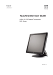
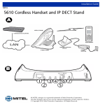
CS150U48V3
Installation & Operation Manual
K01-1504801-00
TABLE OF CONTENTS
1
Product introduction.............................................................................................................. 3
1.1 General Description...................................................................................................................... 3
2 Important Safety Notes ......................................................................................................... 3
2.1 Electrical Warnings....................................................................................................................... 3
2.2 Battery Warnings .......................................................................................................................... 4
2.3 Limited Warranty .......................................................................................................................... 4
2.4 FCC Notice ................................................................................................................................... 5
3 Dimensions……… .................................................................................................................... 6
4 Installation…..…. ...................................................................................................................... 7
4.1 Overview....................................................................................................................................... 7
4.2 Unpacking..................................................................................................................................... 8
4.3 Prior to Installation........................................................................................................................ 8
4.4 Installation .................................................................................................................................... 9
4.4.1 Wall Mounting the UPS ........................................................................................................... 9
4.4.2 Pole Mounting the UPS (Optional) .......................................................................................... 9
4.5 Installing the Battery Trays (Battery Replacement) .................................................................... 10
4.6 Battery Heater - BTH-150-8X (Optional) .................................................................................... 11
4.7 Connecting to Power Source...................................................................................................... 11
4.7.1 Installing the Power Cord ...................................................................................................... 11
4.7.2 Outdoor Power Cord Selection.............................................................................................. 12
4.8 ONT Alarm Connections ............................................................................................................ 13
5 Operation………...................................................................................................................... 13
5.1 Start-Up ...................................................................................................................................... 13
5.2 Controls and Operational LEDs.................................................................................................. 14
5.3 Alarms ........................................................................................................................................ 15
6 Specifications…..................................................................................................................... 16
TABLE OF FIGURES
Figure 1: Dimensions (Front View) ...................................................................................................... 6
Figure 2: Dimensions (Side View) ....................................................................................................... 6
Figure 3: Unit Overview (Front) ........................................................................................................... 7
Figure 4: Unit Overview (Rear)............................................................................................................ 7
Figure 5: Unit Overview (Side) ............................................................................................................ 7
Figure 6: Unit Overview (Bottom) ........................................................................................................ 7
Figure 7: Wall Mount Kit ...................................................................................................................... 9
Figure 8: Pole Mount Kit ...................................................................................................................... 9
Figure 9: Pole Mounting Diagram........................................................................................................ 9
Figure 10: Battery Wiring................................................................................................................... 10
Figure 11: Battery Installation............................................................................................................ 10
Figure 12: Block Diagram of Battery Heater...................................................................................... 11
Figure 13: Battery Heater Dimensions .............................................................................................. 11
Figure 14: AC Wiring (i) ..................................................................................................................... 11
Figure 15: AC Wiring (ii) .................................................................................................................... 11
Figure 16: LED’s and ONT Alarm Connections................................................................................. 13
© 2010 CyberPower Systems (USA), Inc. All Trademarks are property of their owners.
Page: 1 of 17
TABLE OF TABLES
Table 1: Battery Heater Specifications .............................................................................................. 11
Table 2: Block Diagram Descriptions ................................................................................................ 11
Table 3: AC Line Cord ....................................................................................................................... 12
Table 4: Conduit Wires ...................................................................................................................... 12
Table 5: Controls and LED Indicators ............................................................................................... 14
Table 6: Alarms ................................................................................................................................. 15
Table 7: Specifications ...................................................................................................................... 16
TABLE OF APPENDICES
Appendix I: Wall Mount Chart............................................................................................................ 17
© 2010 CyberPower Systems (USA), Inc. All Trademarks are property of their owners.
Page: 2 of 17
1 PRODUCT INTRODUCTION
1.1 General Description
The CS150U48V3 battery backup unit is designed to serve up to two MDU ONTs (Optical Network
Terminal for Multi-Dwelling Use) and can be installed indoors or outdoors. Generally, the product
includes the following features:
• Universal input voltage 100 - 240V
• Up to 150W power output (48VDC)
• Microprocessor-based intelligent control
• Two battery strings (4 or 8 batteries) plus two sets of outputs provide four backup options to meet
customers’ different needs
• Communication interface to provide status updates to the ONT and customer
• PFC (Power Factor Correction) Functionality
• Optional pole mount kit
• Optional battery heater to provide wider temperature range for UPS operation
2 IMPORTANT SAFETY NOTES
• ONLY qualified installation and repair personnel should service this power supply.
• SAVE THESE INSTRUCTIONS - This manual contains important instructions for the CS150U48V3
units that should be followed during installation and maintenance.
• Verify the supplied AC line voltage prior to installation using an AC voltage meter.
• Verify branch circuit breaker or fuse on the service feed is correct for the equipment being installed.
• Batteries may produce hazardous currents and may present a burn hazard if damaged or shorted.
• The following precautions should be observed when working on the unit:
– Remove watches, rings, or other metal objects.
– Wear protective clothing and eye protection when working with batteries and installing this
equipment.
– Always carry a water supply to wash eyes and/or skin if exposed to battery electrolyte. Use tools
with insulated handles.
– Examine the packing container for damage. Notify the carrier immediately if damage is present.
– Do not disassemble the unit.
– Do not operate near water or excessive humidity.
– Keep liquid and foreign objects from getting inside the unit.
– Do not operate close to gas or fire.
– Do not operate unit near leaking liquid or if any liquid residue is present.
– Immediately unplug Power Supply from AC if you see liquid leaking.
2.1 Electrical Warnings
• Servicing this equipment may require working with protective covers removed and utility power
connected. Use extreme caution during these procedures.
• Check that the power cord(s), plug(s), and outlets are in good condition.
© 2010 CyberPower Systems (USA), Inc. All Trademarks are property of their owners.
Page: 3 of 17
2.2 Battery Warnings
• Danger of explosion if battery is incorrectly connected or replaced.
• Worn-out or damaged batteries are considered environmentally unsafe. Always recycle used
batteries or dispose of the batteries in accordance with all federal, state and local regulations.
• Do not open or mutilate batteries. Any gel or liquid emissions from the sealed lead-acid (SLA)
battery contain sulfuric acid, which is harmful to the skin and eyes. Emissions are electrically
conductive and corrosive.
• Batteries may produce explosive gases. Keep all open flames and sparks away from batteries.
• Batteries contain or emit chemicals known to the State of California to cause cancer and birth
defects or other reproductive harm. Battery post terminals and related accessories contain lead
and lead compounds. Wash hands after handling (California Proposition 65).
• Risk of Energy Hazard -12V max. / 7.2 (7) Ampere-Hour battery. Before replacing batteries,
remove conductive jewelry such as chains, wrist watches, and rings. High energy through
conductive materials could cause severe burns.
• Wear protective clothing and eye protection whenever installing, maintaining, servicing, or
replacing batteries.
• If any battery emission contacts the skin, immediately and thoroughly wash with water. Follow
approved chemical exposure procedures.
• Neutralize any spilled battery emission with the special solution contained in an approved spill kit
or with a solution of one pound Bicarbonate of soda to one gallon of water. Report chemical spills
and seek medical attention if necessary.
• Never use un-insulated tools or other conductive materials when installing, maintaining, servicing
or replacing batteries.
• A battery showing signs of cracking, leaking, or swelling should be replaced immediately with a
battery of identical type and rating.
• The battery can energize hazardous live parts inside even when the AC input power is
disconnected.
2.3 Limited Warranty
CyberPower warrants to you, the Initial Purchaser, that the Product will be free from defects in
material and workmanship for three years from the date of original purchase, subject to the terms of
this Limited Warranty. This Limited Warranty gives you specific rights, and you may have other
rights, which vary from State to State or Province to Province.
Any Implied Warranty of Merchantability or for Fitness for a Particular Purpose, if applicable to the
Product, is limited in duration to three years. This provision shall NOT create any Implied Warranty
or Merchantability or of Fitness for a Particular Purpose that would not otherwise apply to the
Product. NOTE: Some States and Provinces do not allow limitations on how long an implied
warranty lasts, so the above limitation may not apply to you.
To be covered you must still be the owner of the Product at the time of the failure that results in the
claim made under this Limited Warranty. Your sole and exclusive remedies are those provided by
this Limited Warranty. This exclusion of other express warranties applies to written and oral express
warranties. CyberPower excludes any liability for personal injury. CyberPower excludes any liability
for direct, indirect, special, incidental, or consequential damages, whether for damage to or loss of
property, loss of profits, business interruption, information or data. This exclusion applies even
though damage or loss is caused by negligence or other fault. NOTE: Some States or Provinces do
not allow the exclusion or limitation of incidental or consequential damages, so the above limitation
may not apply to you.
© 2010 CyberPower Systems (USA), Inc. All Trademarks are property of their owners.
Page: 4 of 17
DO NOT USE FOR MEDICAL OR LIFE SUPPORT EQUIPMENT OR OTHER HIGH RISK
ACTIVITIES.
CyberPower does not sell the PRODUCT for use in high-risk activities. The PRODUCT is not
designed or intended for use in hazardous environments requiring fail-safe performance, including
the operation of nuclear facilities, aircraft navigation or communication systems, air traffic control,
weapons systems, life support or medical applications or for use in any circumstance in which the
failure of the PRODUCT could lead directly to death, personal injury, or severe physical or property
damage, or that would affect operation or safety of any medical or life support device (collectively,
"High Risk Activities"). CyberPower expressly disclaims any express or implied warranty of fitness
for High Risk Activities. CyberPower does not authorize use of any PRODUCT in any High Risk
activities.
ANY SUCH USE IS IMPROPER AND IS A MISUSE OF A CYBERPOWER PRODUCT.
The Limited Warranty is governed by the laws of the United States and the State of Minnesota,
without reference to conflict of law principles. The application of the United Nations Convention of
Contracts for the International Sale of Goods is expressly excluded.
2.4 FCC Notice
This equipment has been tested and found to comply with the limits for a Class B digital device,
pursuant to part 15 of the FCC Rules. These limits are designed to provide reasonable protection
against harmful interference in a residential installation. This equipment generates, uses and can
radiate radio frequency energy and, if not installed and used in accordance with these instructions,
may cause harmful interference to radio communications. However, there is no guarantee that
interference will not occur in a particular installation. If this equipment does cause harmful
interference to radio or television reception, which can be determined by turning the equipment off
and on, the user is encouraged to try to correct the interference by one or more of the following
measures: (1)Reorient or relocate the receiving antenna. (2) Increase the separation between the
equipment and receiver. (3) Connect the equipment into an outlet on a circuit different from that to
which the receiver is connected. (4) Consult the dealer or an experienced radio/TV technician for
help.
CAUTION: Any changes or modifications not expressly approved by Cyber Power could void the
authority granted by the FCC to operate this equipment.
© 2010 CyberPower Systems (USA), Inc. All Trademarks are property of their owners.
Page: 5 of 17
3
DIMENSIONS
17.14 inch (435.4 mm)
15.75 inch (400.1 mm)
7.09 inch (180.1 mm) 5.79 inch (147.1 mm)
15.30 inch (388.6 mm)
16 inch (406.4 mm)
Figure 1: Dimensions (Front View)
15.04 inch (382 mm)
15.75 inch (400.1 mm)
9.06 inch (230.1 mm)
Figure 2: Dimensions (Side View)
© 2010 CyberPower Systems (USA), Inc. All Trademarks are property of their owners.
Page: 6 of 17
4
INSTALLATION
4.1 Overview
1
2
4
3
5
8
6
12
7
10
9
6
11
Figure 3: Unit Overview (Front)
13
1. Internal AC power wiring inlet
2. Alarm Silence and Cold Start button
3. LED Indicators (AC/DC MODE, BATTERY
MISSING 1, BATTERY MISSING 2, DC
OUTPUT)
4. DC Output and Telemetry receptacles
5. Battery wiring harness plug-in
6. Door clasp
7. Door padlock hasp
8. Door ground and bonding stud
9. Battery tray mounting screw
10. Battery tray
11. Customer option ground stud
12. Wire management bracket
13. Wall-mount bracket
Figure 4: Unit Overview (Rear)
3/4" knock-out
1/2” knock-out
3/4”, 1 1/4”, 1 3/4” concentric knock-out
3/8” knock-out (for recessed mounting)
Figure 5: Unit Overview (Side)
3/4”, 1 1/4”, 1 3/4” concentric knock-out
Figure 6: Unit Overview (Bottom)
© 2010 CyberPower Systems (USA), Inc. All Trademarks are property of their owners.
Page: 7 of 17
4.2 Unpacking
Inspect the Battery Backup Unit upon receipt. The box should contain the following:
• Battery Backup Power Supply Unit x 1
• Battery Shelves x 2
– Battery Tray x 2
– Battery Tray Clamp x 2
– M4 x 8 Truss head Screws x 8 (secure clamp to shelf)
– M4 x 8 Truss head Screws x 4 (secure shelf to enclosure)
• Accessory Pack
– Terminal Connectors x 2
– Cable Ties x 6
– Battery Terminal Jumper x 6
– Battery Wire Harness Assemblies x 2
– User’s Manual x 1
• Wall Mount Kit
– Wall Mount Bracket x 2
– M8 Flange Nut x 4
• (OPTIONAL) Pole Mount Kit
– Pole Mount Bracket x 3
– M8 Flange Nut x 6
– M8 x 25L Hex Head Screws (clamp center bracket to side brackets) x 4
– M8 Lock Washers x 4
– M8 Flat Washers x 4
• (OPTIONAL) Battery Heater
– Battery Heater Sheet x 1
– Circuit Breaker with Outlet x 1
4.3 Prior to Installation
Installation of the unit must be performed by skilled technicians and electricians familiar with
electrical equipment. Do not allow unqualified personnel to handle, install, or operate the
equipment. The installation must comply with both the requirements of the National Electrical
Code (ANSI/NFPA 70, latest issue), and local codes.
CAUTION: When batteries are installed in the UPS, the total weight will exceed 50 pounds. Make
sure the fasteners used to attach to the wall are of sufficient strength to securely hold the UPS.
© 2010 CyberPower Systems (USA), Inc. All Trademarks are property of their owners.
Page: 8 of 17
4.4 Installation
4.4.1 Wall Mounting the UPS
1. Remove the UPS from the carton.
2. Get the wall mount kit.
3. Use the nuts included in the kit.
Attach both wall mount brackets to
the threaded posts on the back side
of the UPS enclosure as shown on
the right.
4. Reference the Wall Mount Chart
(scaled-down) in Appendix I to
mark the four mounting hole
locations.
5. Pre-drill the marked hole locations
to a suitable size (M8 is
recommended) for the fasteners
being used.
6. Install the fasteners and mount the
UPS to the wall.
4.4.2 Pole Mounting the UPS (Optional)
1. Remove the UPS from the carton.
2. Get the pole mount kit (ordered
separately)
3. Using the nuts included in the kit,
attach the left and right pole mount
brackets to the threaded posts on
the back side of the UPS
enclosures as shown.
4. Thread the (4) M8 x 25L hex head
screws with a lock washer and flat
head washer onto the center pole
mount bracket.
5. Using pole mount straps (not
provided), attach the center bracket
to the pole.
6. Hang the UPS (batteries not
installed) onto the center poll mount
bracket which is already on the poll.
7. Tighten the 4 screws.
Wall Mount
Bracket Post
Poll Mount
Bracket Post
Figure 7: Wall Mount Kit
Poll Mount
Bracket (Left)
Center
Bracket
Poll Mount
Bracket
(Right)
Tread screw and two washers
onto center bracket
Figure 8: Pole Mount Kit
Note: Using stainless or galvanized
steel straps with a width of 1-inch is
recommended.
"Warning: Risk of Electric Shock.
Mount the unit at a height greater
than 25cm from the ground surface."
Figure 9: Pole Mounting Diagram
© 2010 CyberPower Systems (USA), Inc. All Trademarks are property of their owners.
Page: 9 of 17
4.5 Installing the Battery Trays (Battery Replacement)
The batteries must be installed and wired to the battery tray prior to installing inside the UPS
enclosure.
1. Slide the battery tray out of the UPS.
2. Get the new batteries and install batteries onto the battery tray as shown below.
Battery Jumpers
Secure harness
with cable ties
Wire Strain Relief
Wire Harness (Vo+)
Wire Harness (Vo-)
Battery tray
mounting hole
Figure 10: Battery Wiring
3. Install the battery clamp using the (4) screws provided. Tighten the screws.
4. Wire the batteries:
a. Add wire jumpers (spade lugs) to interconnect the batteries.
b. Attach the red wire on the wiring harness to the positive terminal (red) of battery.
c. Attach the black wire on the wiring harness to the negative terminal (black) of battery.
d. Secure the harness assembly to the battery clamp with cable ties.
5. Carefully slide the battery tray into the enclosure and secure with the M4 x 8 Truss head screws
provided.
Note: The UPS should be secured on the
wall/pole before sliding the battery trays into
the UPS.
6. Plug the connectorized end of each wiring
harness into the receptacle on the front face
of the UPS.
Battery Harness
Wire Plug-in
Note: For customers who initially ordered
one-battery-string configured cabinet, please
contact CyberPower if upgrading to
two-battery-string configuration is needed.
Battery Tray
Mounting Screw
Note: The door must be locked with padlock
after installation is complete.
Battery Type
The battery is a standard sealed lead acid
battery rated at 12Vdc / 7.2 (7) Ah. When
required, the battery may be replaced with
an approved 12Vdc / 7.2 (7) Ah battery.
Figure 11: Battery Installation
Batteries are considered HAZARDOUS WASTE and must be disposed of properly.
Most retailers that sell batteries collect used batteries for recycling.
© 2010 CyberPower Systems (USA), Inc. All Trademarks are property of their owners.
Page: 10 of 17
4.6 Battery Heater - BTH-150-8X (Optional)
Heater
Input Voltage
Wattage
Line Cord Thermostat
Thermal Fuse
Mat Mounted Thermostat
44
33
2
1
(AC) 110V/60Hz
120W
OPEN:15˚C
CLOSE:5˚C
84˚C
OPEN:50˚C
CLOSE:35˚C
Table 1: Battery Heater Specifications
Figure 12: Block Diagram of Battery Heater
Note: Make sure that the input voltage for the battery heater
is 110V.
DESCRIPTION:
Location
1
2
Device
Power Connector
Line Cord Thermostat
3
4
Thermal Fuse
Mat Mounted
Thermostat
Function
AC Input
In low temperature conditions the thermostat
will allow power to flow to the heater mat coil
Final protection allows safe failure
The thermostat is to keep the temperature of
the battery heater within a pre-set range.
DIMENSIONS:
Table 2: Block Diagram Descriptions
Heater Area
16
260
2-Ø4
65
8
28.55 20
37.55
12
28
Thermal Switch & Thermal Fuse
On Back
4
296
115.5
Figure 13: Battery Heater Dimensions
4-Ø10
280
4.7 Connecting to Power Source
4.7.1 Installing the Power Cord
1. Remove the 4 terminal strip cover screws
(upper left hand corner)
2. Remove any convenient 3/4” knock-out of
Remove
the UPS enclosure.
terminal cover
3. Install a Heyco Liquid Tight Cordgrip
(LTF-11) or equivalent, if not using conduit.
Remove
4. With the power cord disconnected from any knock-out and
add strain relief
supply source, route the power cord
through the strain relief and attach it to the or conduit here
terminal strip.
5. Tighten the strain relief around the power
cord to secure.
6. Re-install the terminal strip cover.
7. Plug-in the molded power plug on the front
of the UPS control panel.
Figure 14: AC Wiring (i)
Note: Be certain to utilize environmentally
sealed strain-reliefs, cordgrips, or conduit at
the AC Power entry point.
Note: Be sure to connect the power cord to
each terminal (L/N/G) correctly and securely.
Figure 15: AC Wiring (ii)
© 2010 CyberPower Systems (USA), Inc. All Trademarks are property of their owners.
Page: 11 of 17
4.7.2 Outdoor Power Cord Selection
1. If an outdoor AC Line cord is selected to connect the unit to AC wall outlet, be sure that the
selection criterion in the following table are fully complied.
Outdoor Use
Cord Rating
Wire (AWG)
Three conductors,
current rating 10A,
VW-1, 105℃,
125/250V
Check
specifications of
liquid tight cable
gland to determine
the outside
diameter of the
wire.
(O.D. > 6.8mm;
18AWG min. for
each inner wire)
Attachment Plug
Use cord type with
15A, 125V (NEMA
the suffix "W", "W-A" 5-15P) or 15A, 250V
or the words "Water (NEMA 6-15P)
resistant" or
"Outdoor" marked on
the flexible cord
Flexible Cord Type
SP-2, SPE-2, SPT-2,
NISP-2, NISPE-2,
NISPT-2, SP-3, SPE-3,
SPT-3
SV, SVE, SVO, SVOO,
SVT, SVTO, SVTOO
SJ, SJE, SJO, SJOO,
SJT, SJTO, SJTOO
S, SE, SO, SOO, ST,
STO, STOO
Table 3: AC Line Cord
2. The connection of the power cord should also be in accordance with Article 110.14 of
ANSI/NEPA 70.
3. Using pin terminals (as shown in the Figure 14) for the power cord at the end connected to
terminal strip is recommended.
"Warning - Risk of Electric Shock. Connect plug of outdoor power cord only to a covered Class A
GFCI receptacle that has an enclosure that is weatherproof with the attachment plug cap inserted or
removed."
4. If conduit is used, be sure to choose wires in accordance with the following criterion.
Wire Gauge
(AWG)
Wire Type
10-18 AWG
Copper Conductors
Copper conductors
Tightening Torque
(lb-in)
7
Minimum temperature
rating of conductors
75°C
Table 4: Conduit Wires
"Warning - Risk of Electric Shock. Install wires going through conduit only on a circuit protected
by a Class A GFCI."
"Warning: Power supply cord must not be attached to the building surface, nor run through walls,
ceilings, floors and similar openings in the building structure."
"Warning: The socket outlet shall be installed near the equipment and shall be easily accessible."
"Warning: To reduce the risk of fire, connect the unit only to a circuit provided with Listed 20
Amperes circuit breaker in accordance with the National Electrical Code, ANSI/NFPA."
Note: Wiring, liquid tight fittings, conduit and cable glands shall be selected in accordance with
Article 300 of ANSI/NFPA 70.
Note: Before installing the unit, confirm that there is listed IEC 61643-12 or UL1449 low surge
protective device with surge protection level less than 2.5KV being connected between the
unit and the power source.
Note: Surge Arrestors or Transient Voltage Surge Suppressor external to the equipment to reduce
overvoltages or to bypass surge current shall be installed per Article 280 or 285 of ANSI/NFPA 70.
Note: Be certain to keep coolant or oil away from the unit.
© 2010 CyberPower Systems (USA), Inc. All Trademarks are property of their owners.
Page: 12 of 17
4.8 ONT Alarm Connections
1. Route the 7-wire cable back from the ONT enclosure to the UPS.
2. Remove any convenient 3/4” knock-out of the UPS enclosure.
3. Install a strain relief in the knock-out hole.
4. Route the power cable up through the strain relief.
5. Trim the cable to the desired length and strip back approximately 2” of the jacket.
6. Using a jeweler’s standard blade screwdriver, attach the wires to the connector referencing the
ONT pin-out information.
7. Tighten the strain relief around the power cord.
Note: Be certain to utilize environmentally sealed strain-reliefs, cordgrips, or conduit at the cable
exit point.
Note: Output wires should be installed in accordance with Article 800 of ANSI/NFPA 70.
Figure 16: LED’s and ONT Alarm Connections
5
OPERATION
5.1 Start-Up
1. Supply AC power.
2. During initial start-up, observe the following:
a. The AC/DC Mode LED illuminates (Green). The UPS is running on AC (utility) power and the
batteries are charging.
b. The DC Output LED illuminates (Green). The UPS is outputting DC power to the ONT.
3. Route and secure the cables to the wire management brackets.
4. Close and latch the front cover of the UPS.
© 2010 CyberPower Systems (USA), Inc. All Trademarks are property of their owners.
Page: 13 of 17
5.2 Controls and Operational LEDs
Four status LEDs are displayed on the front panel of the UPS. The operation of the UPS can be
assessed using these LEDs.
Indicator
Color
Condition
Black
Press and hold the button for 1 second to
silence the audible alarm for 24 hours.
Press and hold the button for 10 seconds to
shut down the output voltage. The UPS will
restart after 15 seconds.
Note: The second function can be utilized to
reset an output if it has been shut-down due to
an over-current or short condition, and the fault
has been removed.
Cold Start Button
Black
The cold start allows a start-up of the system
after a power outage and the batteries have
been replaced.
Note: Before using the Cold Start feature,
make sure the batteries are fully charged.
AC/DC Mode LED
Green/
Orange
When the LED is green, the UPS is running on
AC power.
When the LED is orange, the UPS is running
on battery power.
Red
The appropriate battery string is not connected
or needs replacing.
Alarm Silence Button
Battery Missing LED 1&2
DC Output LED
Green
When lit, the UPS is outputting DC power
whether in utility or battery power mode.
Table 5: Controls and LED Indicators
© 2010 CyberPower Systems (USA), Inc. All Trademarks are property of their owners.
Page: 14 of 17
5.3 Alarms
There are audible and visual alarm signals to alert the customer to abnormal and/or service
affecting conditions present in the UPS.
Condition
Status LED
Alarm
Interface
Normal
AC/DC Mode
LED is
GREEN
No Audible
Alarm
“ON Batt”
signal in low
state
On Battery
AC/DC Mode
LED is
ORANGE
Beeps twice
every 5
seconds
“ON Batt”
signal in open
state
AC input failure; Battery is
supplying the power
Low Battery
N/A
Beeps twice
every second
“Low Batt”
signal in open
state
When the battery is nearly
depleted, the audible alarm
will beep twice every one
second.
Battery
Missing
Missing
Battery LED
On
No Audible
Alarm
“Missing Batt”
signal in open
state
The Missing Battery LED
will be illuminated due to a
missing battery.
“Replace Batt”
signal in open
state
The unit will perform a
periodic battery test
automatically without
disrupting operation. If the
battery needs to be
replaced, the Missing
Battery LED will be
illuminated.
Replace
Battery
Missing
Battery LED
On (RED)
No Audible
Alarm
Description
Condition normal
Table 6: Alarms
© 2010 CyberPower Systems (USA), Inc. All Trademarks are property of their owners.
Page: 15 of 17
6
SPECIFICATIONS
Model Number
Input:
Rating Voltage/Frequency
Input Voltage Range
Frequency Range
P.F.
Output:
Output Power Continuous
Output Power Max
Output Voltage Range
Output Current (max Load)
Ripple
Noise
Efficiency
Output Connection
Battery
Battery Type
Numbers of Battery
Replaceable
Surge Protection and Filtering
Lightning / Surge Protection
Warning Diagnostics
Indicators
Management
Auto-Charge
Communication Interface
Physical
Maximum Dimensions (W*D*H)
Weight
Environmental Specifications
Operating Temperature
Operating Humidity
Max Operating Elevation
Max Storage Elevation
Storage Temperature
Compliance
CS150U48V3
100 - 240V / 50 - 60Hz
90 - 264Vac
47 - 63Hz
> 0.9 at Rating Voltage and Max Load
150W
170W, 10sec Max.
42V - 58Vdc
3.1A Nominal
< 30mVrms
< 120mVp-p
> 85% at Rating Voltage and Max Load
7-Pin communication signals connector
(DECA ME030-5007), Max 12AWG
Sealed, Maintenance Free Lead-Acid Battery
7.2 (7) AH/12V (8-standard, 4-factory orderable option)
Yes
GR-1089-CORE Sect 4
AC (AC/Battery Mode Indicator), Output (Output On/Off
Indicator), Battery (Battery Missing/Replacement Indicator)
Yes
On Battery, Replace Battery, Battery Missing, Low Battery
389mm x 230mm x 400mm
28kg (with 8pcs battery)
-4°F to 131°F (-20°C to 55°C)
0 to 95% non-condensing within enclosure
10,000ft (3,000m)
50,000ft (15,000m)
-4°F to 131°F (-20°C to 55°C)
CSA/UL 60950, EN 60950, EN 55022 Class B, FCC Part
15 Class B, GR-63 Sect 4.2 Fire Resistance,
GR-1089 Sect 3 Emissions, Sect 4 Lightning and AC
Power Fault, Sect 7 Electrical Safety.
Table 7: Specifications
© 2010 CyberPower Systems (USA), Inc. All Trademarks are property of their owners.
Page: 16 of 17
7.09 inch (180 mm)
APPENDIX I - Wall Mount Chart
16 inch (406.4 mm)
Recommended Screw Dimensions
M8 x 25L or 3/8” x 1”L
© 2010 CyberPower Systems (USA), Inc. All Trademarks are property of their owners.
Page: 17 of 17