1
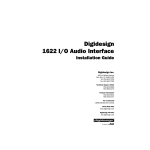
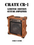
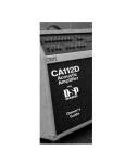
CA125D
Acoustic Amplifier
User’s Guide
CA125D Acoustic Amplifier
Table of Contents:
About the Crate Acoustic CA125D . . . . . . . . . . . . . . . . . 3
The Front Panel . . . . . . . . . . . . . . . . . . . . . . . . . . . . . . . . . 4
The Rear Panel. . . . . . . . . . . . . . . . . . . . . . . . . . . . . . . . . . 5
To Eliminate Instrument Feedback . . . . . . . . . . . . . . . . . 6
The DSP Section . . . . . . . . . . . . . . . . . . . . . . . . . . . . . . . . 6
The Tilt Back Feature . . . . . . . . . . . . . . . . . . . . . . . . . . . . 7
System Block Diagram . . . . . . . . . . . . . . . . . . . . . . . . . . . 7
Technical Specifications. . . . . . . . . . . . . . . . . . back cover
Declaration of Conformity
Manufacturer’s Name: SLM Electronics
Corporate Headquarters: 1901 Congressional Drive, St. Louis, Missouri 63146
Primary Production Facility: 700 Hwy 202 W, Yellville, Arkansas, 72687
Product Type: Audio Amplifier
Products meet the regulations for compliance marking under:
ETL standards UL6500, UL60065, or UL813
CSA standards E60065 or C22.2 No.1-M90
CE safety standard EN60065
CE EMC standards EN55103 or EN55013 and EN61000
FCC standards 47CFR 15.107 and 15.109 Class A
C-tick designation Level 2, ABN #56748810738, ARBN# N222
KETI standard K60065 (limited model approval)
Compliance Support Contact: SLM Electronics, Attn: R&D Compliance Engineer
1901 Congressional Drive, St Louis, Missouri, 63146 • Tel.: 314-569-0141, Fax: 314-569-0175
CAUTION
PRECAUCION
ATTENTION
RISK OF ELECTRIC SHOCK
DO NOT OPEN
RIESGO DE CORRIENTAZO
NO ABRA
RISQUE D'ELECTROCUTION
NE PAS OUVRIR
WARNING: TO REDUCE THE RISK OF FIRE OR ELECTRIC SHOCK, DO NOT EXPOSE
THIS APPARATUS TO RAIN OR MOISTURE. TO REDUCE THE RISK OF ELECTRIC
SHOCK, DO NOT REMOVE COVER. NO USER-SERVICEABLE PARTS INSIDE. REFER
SERVICING TO QUALIFIED SERVICE PERSONNEL.
PRECAUCION: PARA REDUCIR EL RIESGO DE INCENDIOS O DESCARGAS ELECTRICAS, NO PERMITA QUE ESTE APARATO QUEDE EXPUESTO A LA LLUVIA O LA HUMEDAD. PARA DISMINUOIR EL
RIESGO DE CORRIENTAZO. NO ABRA LA CUBIERTA. NO HAY PIEZAS ADENTRO QUE EL USARIO
PUEDO REPARAR DEJE TODO MANTENIMIENTO A LOS TECHNICOS CALIFICADOS.
ATTENTION: PROTÉGEZ CET APPAREIL DE LA PLUIE ET DE L'HUMIDITÉ AFIN D'ÉVITER TOUT
RISQUE D'INCENDIE OU D'ÉLECTROCUTION. POUR REDUIRE D'ELECTROCUTION NE PAS ENLEVER
LE COUVERCLE. AUCUNE PIECE INTERNE N'EST REPRABLE PAR L'UTILISATEUR. POUR TOUTE
REPARATION, S'ADRESSER A UN TECHNICIEN QUALIFIE.
IMPORTANT SAFETY INSTRUCTIONS
• READ, FOLLOW, HEED, AND KEEP ALL INSTRUCTIONS AND WARNINGS.
• DO NOT OPERATE NEAR ANY HEAT SOURCE AND DO NOT BLOCK ANY VENTILATION OPENINGS ON THIS APPARATUS. FOR PROPER OPERATION, THIS UNIT REQUIRES 3”
(75CM) OF WELL VENTILATED SPACE AROUND HEATSINKS AND OTHER AIR FLOW PROVISIONS IN THE CABINET.
• DO NOT USE THIS APPARATUS NEAR SPLASHING, FALLING, SPRAYING, OR STANDING LIQUIDS.
• CLEAN ONLY WITH LINT-FREE DAMP CLOTH AND DO NOT USE CLEANING AGENTS.
• ONLY CONNECT POWER CORD TO A POLARIZED, SAFETY GROUNDED OUTLET WIRED TO CURRENT ELECTRICAL CODES AND COMPATIBLE WITH VOLTAGE, POWER, AND
FREQUENCY REQUIREMENTS STATED ON THE REAR PANEL OF THE APPARATUS.
•
•
•
•
•
•
PROTECT THE POWER CORD FROM DAMAGE DUE TO BEING WALKED ON, PINCHED, OR STRAINED.
UNPLUG THE APPARATUS DURING LIGHTNING STORMS OR WHEN UNUSED FOR LONG PERIODS OF TIME.
ONLY USE ATTACHMENTS, ACCESSORIES, STANDS, OR BRACKETS SPECIFIED BY THE MANUFACTURER FOR SAFE OPERATION AND TO AVOID INJURY.
WARNING: TO REDUCE THE RISK OF ELECTRIC SHOCK OR FIRE, DO NOT EXPOSE THIS UNIT TO RAIN OR MOISTURE.
SERVICE MUST BE PERFORMED BY QUALIFIED PERSONNEL.
OUR AMPLIFIERS ARE CAPABLE OF PRODUCING HIGH SOUND PRESSURE LEVELS. CONTINUED EXPOSURE TO HIGH SOUND PRESSURE LEVELS CAN CAUSE PERMANENT HEARING IMPAIRMENT OR LOSS. USER CAUTION IS ADVISED AND EAR PROTECTION IS RECOMMENDED IF UNIT IS OPERATED AT HIGH VOLUME.
EXPLANATION OF GRAPHICAL SYMBOLS:
EXPLICACION DE SIMBOLOS GRAFICOS:
EXPLICATION DES SYMBÔLES GRAPHIQUES:
2
"DANGEROUS VOLTAGE"
=
“VOLTAJE PELIGROSO”
"DANGER HAUTE TENSION"
"IT IS NECESSARY FOR THE USER TO REFER TO THE INSTRUCTION MANUAL"
=
“ES NECESARIO QUE EL USUARIO SE REFIERA AL MANUAL DE INSTRUCCIONES.”
"REFERREZ-VOUS AU MANUAL D'UTILISATION"
CA125D Acoustic Amplifier
About the Crate Acoustic CA125D:
D
esigned for the performing artist,
Crate’s CA125D Acoustic Amplifier
gives you more of what you want.
More power. More clarity. More control. And,
more freedom. Imagine: microphone quality
sound, without feedback. And without being
“chained” to a mic stand!
More power: twin 50-watt RMS power
amplifiers drive a pair of specially designed
high fidelity 8” low frequency transducers for
plenty of volume and low end punch.
More clarity: a separate 25-watt RMS
power amp drives a highly efficient Piezo
tweeter for clean crisp highs and natural
midrange blend. A tweeter level control on
the rear panel allows you to adjust the high
frequency output to suit your taste.
More control: three independent channels,
each with its own gain and reverb/effects
controls. The main Instrument channel features an “Active/Piezo” switch to properly
match the pickups of your instrument, plus a
three-band rotary EQ with variable contour –
for total control of the critical midrange frequencies. An easy-to-use feedback elimination
circuit with frequency select and cut controls
lets you kill feedback without sacrificing
sound quality. Plus a footswitchable chorus
with depth and rate controls.
The Vocal/Aux channel offers both low
and high impedance inputs for both kinds of
microphones, with phantom power on the
Low-Z input. The third “Aux” channel allows
the use of a rhythm machine, background
tape, or another mic or instrument.
Still more: The master section features
reverb and effects return controls, a five-band
graphic EQ, and the master level control. A
footswitch jack on the rear panel provides
control for reverb and chorus. Level-controllable XLR and 1/4” balanced line outs allow
you to patch into house sound boards or
recording consoles, plus an effects loop linein/line-out setup allows connection of external effects.
Enough already? Not for us. The CA125D
features Crate’s Digital Signal Processing (DSP)
for a variety of digital reverbs, effects and
delays specifically designed for acoustic
instruments.
The CA125D features a flip-out locking bar
underneath the cabinet which allows you to
tilt the amplifier back for increased coverage
and projection.
The CA125D was designed, evaluated,
tweaked and redesigned by musicians and
music loving engineers. Highly sophisticated
computer driven assembly machines and
highly skilled assemblers use only the finest
components to produce each amp. Every cabinet is hand-built and hand-covered by trained
craftsmen. The final assembled product is
tested – and played – by skilled musician/
technicians. It is only after the amplifier has
passed this barrage of picky people that it
gets packed up and shipped out.
The CA125D Acoustic Amplifier. Designed
to be its best, so you can sound your best!
To get this amplifier to sound its best,
read this user’s guide prior to its use.
To keep this amplifier looking its best, avoid
abrasive cleansers. Wipe the cabinet clean
using a slightly dampened cloth. Never use
brass cleaners on the hardware since they
could damage their protective coatings.
3
CA125D Acoustic Amplifier
The Front Panel:
1
2
3
15
4
5
6
7
16
17
18
8
9
10
11
12
13
14
19
20
21
22
23
24
The Instrument Channel:
1: Input. The signal output from your acoustic instrument may be connected
here by means of a shielded instrument cable.
2: Active/Piezo. Use this switch to match the type of pickup used in your
instrument. For active electronic pickups, set the switch to “active” (switch
out). For passive/magnetic pickups, set it to “piezo” (switch depressed).
3: Gain. This serves as the input level control for the instrument channel. For
the best signal to noise ratio set this control so the Peak LED (#4) flashes on
strong signals.
4: Peak. This LED flashes when the signal level into the preamp approaches
clipping. Adjust the Gain control (#3) until a strong signal causes this LED
to flash.
5: Low. This serves as the instrument channel’s primary bass control. Adjust
this control to get the best sounding bass response for your instrument.
Excessive boost of the low control can cause an unnatural howling and
should be avoided.
6: Mid. This serves as the instrument channel’s primary midrange control.
Adjust this control to get the best projection and midrange tones for your
instrument. The center point of the mid control is chosen by the setting of
the Contour control (#7).
7: Contour. Use this control to set the center point of the Mid control (#6). Set
this control at the frequency which gives you the most natural-sounding
midrange tones.
8: High. This serves as the instrument channel’s primary treble control.
Adjust this control so your high notes and harmonic overtones are lively
but not overpowering.
9: Freq. Use this control along with the Cut control (#10) to eliminate instrument feedback. For information on the proper use of this control, please
read the section entitled “To Eliminate Feedback.”
10: Cut. Use this control along with the Freq control (#9) to eliminate instrument feedback. For information on the proper use of this control, please
read the section entitled “To Eliminate Feedback.”
11: Rev/Eff Send. Use this control to adjust the amount of internal Digital
Effect and/or external effect (if used) for Channel 1.
12: On/Off. This switch, when depressed, applies the internal chorus effect to
the instrument channel.
13: Chorus Depth. Use this control to adjust the magnitude of the chorus
effect. Rotating this control clockwise increases the intensity of the effect.
14: Chorus Rate. Use this control to adjust the rate of the chorus effect.
Rotating this control clockwise increases the rate at which the effect occurs.
4
25
26
27
The Vocal/Aux Channel:
15: Low-Z. The signal output from a low impedance microphone may be connected here by means of a shielded, balanced microphone cable terminated
with an XLR connector. The Low-Z jack has 15 volts phantom power
applied to pins 2 and 3. (Mics not requiring phantom power will not be
affected.)
16: Hi-Z. The signal output from a high impedance microphone or a line level
signal may be connected here by means of a shielded signal cable terminated with a 1/4” tip/sleeve connector.
17: Gain. This serves as the input level control for the vocal/aux channel.
Adjust this control for the best mix with the signals from the other channels.
18: Rev/Eff Send. Use this control to adjust the amount of internal reverb
and/or external effect (if used) for the vocal/aux channel.
The Aux Channel:
19: Hi-Z. The signal output from a high impedance microphone or a line level
signal may be connected here by means of a shielded signal cable terminated with a 1/4” tip/sleeve connector.
20: Gain. This serves as the input level control for the aux channel. Adjust this
control for the best mix with the signals from the other channels.
21: Rev/Eff Send. Use this control to adjust the amount of internal reverb
and/or external effect (if used) for the aux channel.
The Effects Section:
22: Mode. Use this control to select the type of digital signal processing applied
to the output signal. For a listing of the effects, please see the section entitled “The DSP Section.”
23: Rev Level. Use this control to adjust the amount of the internal reverb.
Rotating the control clockwise increases the amount of effect.
24: Eff Return. Use this control to adjust the amount of effect applied from an
external signal processor (if used).
The Master Section:
25: Graphic EQ. Use these sliders to control the output frequencies indicated
below each control. The center position of each control is flat (no boost or
cut). Use the graphic EQ to adjust the output of the amplifier to best suit
your tastes and to compensate for room acoustics.
26: Level. use this control to adjust the overall output level of the amplifier.
27: Power. Use this switch to apply power to the amplifier. The amp is on when
the top of the switch is depressed and off when the bottom of the switch is
depressed. this switch illuminates when the amplifier is on.
CA125D Acoustic Amplifier
The Rear Panel:
36
28: Footswitch. Connect the supplied two-button footswitch here for
remote on/off control of the internal reverb and chorus. (When connected, the footswitch overrides the front panel chorus on/off
switch.)
Note: This is a STEREO jack: tip controls the chorus, ring controls the
reverb, sleeve is ground. Use only a footswitch equipped with a stereo
1/4” plug.
29: Effects Loop Send. When using an external signal processor, connect
this jack to the input of the effect by means of a shielded signal cable.
30: Effects Loop Return. When using an external signal processor, connect this jack to the output of the effect by means of a shielded signal
cable.
31: High Z Balanced Line Output. Use this jack to connect a high impedance, line level signal to a house sound board, a recording console or
an external power amplifier by means of an 1/4” stereo plug-terminated cable. (Ring is signal +, tip is signal -, and sleeve is ground.)
32: Low Z Balanced Line Output. Use this jack to connect a low impedance, line level signal to a house sound board, a recording console or
an external power amplifier by means of an XLR-terminated cable.
(Pin 1 is ground, pin 2 is signal +, and pin 3 is signal -.)
35
34 33
32
31
30
29
28
33: Gnd Lift. This switch, when depressed, electronically disconnects the
Low Z Balanced Output jack’s chassis ground connection. If you
experience excessive noise when using the Low Z Balanced Output
jack, depress this switch.
34: Line Output Level. Use this control to adjust the output level of the
line out signal. (This control works independently from the amplifier’s master level control.)
35: Tweeter Level. Use this control to adust the signal output level from
the CA125D’s internal tweeter. Rotating this control counter-clockwise reduces the tweeter’s output level.
36: AC Line Cord. The grounded power cord should only be plugged
into a grounded power outlet that meets all applicable electrical
codes and is compatible with the voltage, power and frequency
requirements stated on the rear panel. Do not attempt to defeat the
safety ground connection!
5
CA125D Acoustic Amplifier
To Eliminate Instrument Feedback:
One of the most common problems encountered when amplifying
acoustic instruments, especially in small environments, is feedback.
Acoustic instruments typically have inherent qualities which cause resonant feedback at specific frequencies. Instrument tone controls and sound
board equalizers are helpful in getting rid of the problem, but they typically operate around relatively wide frequency bands. This almost always
means the musician must sacrifice sound quality in his quest to do away
with feedback. But since Crate’s feedback elimination circuit isolates only
the offending frequency, instrument feedback from the CA125D can be
eliminated without affecting the overall sound.
Chances are, you may not have a problem with feedback at all. In that
case, leave the CA120D’s Freq and Cut controls fully counter-clockwise.
However, if you do encounter feedback while playing, set the Cut control
to -30dB (fully clockwise) and adjust the Freq control until the feedback is
gone. Reduce the Cut to the 12 o’clock position and readjust the Freq control as needed. Continue reducing the Cut control and readjusting the
Freq control until there is no more feedback with the Cut control as far
counter-clockwise as possible. This approach effectively eliminates
instrument feedback without sacrificing the quality of your sound.
The DSP Section:
The CA125D features Crate’s On-Board Digital Signal
Processing (DSP) technology that was designed specifically for
use with acoustic instruments and vocals. This provides a
large selection of digital reverbs, effects and delays. Select the
type of effect desired by rotating the Mode control (#22). This
control is divided into five sections: Small Area Reverbs
(SAR), Large Area Reverbs (LAR), Special Reverbs (SPR),
Delays (DLY) and Multiple Effects (Multi).
The following chart provides a list of the DSP settings along with a brief description of each effect.
SAR:
Small Room 8’ x 8’ empty room w/hardwood floor
Small Rehearsal Hall 20’ x 40’ hall, wood floors, hard walls
LAR:
Large Hall 50’ x 100’ hall, about 50 persons
Concert Hall 5000-seat hall, full crowd
SPR:
Plate Reverb Simulates studio steel plate reverb
Spring Reverb Simulates multi-spring reverb tank
DLY:
Slapback, short 125ms delay + reverb
Slapback, Med-short 240ms delay + reverb
Slapback, Medium 350ms delay + reverb
Slapback, Long 557ms delay - 630’ travel time
Multi:
Short Med. Surface 280ms delay w/21.8% regen + reverb
Medium Hard Surface 335ms delay w/26.5% regen + reverb
Chor-Delay 400ms delay with modulation
Chor-Verb Hall reverb w/modulated pre-delay
Slap-Verb Medium hall w/200ms pre-delay
Instrument Doubler Simulates second track slightly out-of-sync
6
CA125D Acoustic Amplifier
The Tilt Back Feature:
There are instances when you may
need to tilt the amplifier back to better project its sound towards your ears (as a nearfield monitor) or towards your audience
(for better coverage). The CA125D features
a tilt back device underneath its cabinet for
this purpose. To utilize this tilt back feature,
refer to the illustration below and follow
these simple steps:
1 Carefully lean the cabinet back until the front of the cabinet is several inches off the floor.
2 Pull the tilt back bar down (to
unlock it from its holder) and swing
it forward until it locks into place.
3 Lower the front of the amplifier
until it rests on the tilt back bar.
(To return the bar to its traveling
position, reverse these steps)
CAUTIONS:
Avoid trapping your hand under the tilt
back bar.
1
2
Always make sure the bar is securely locked
in place before lowering the amplifier.
Do not sit on or rest your foot on the amplifier when it is in the tilt back position.
3
System Block Diagram:
master
effects line out
instrument
channel
input
filter
active
piezo
tones
freq cut
gain
low mid cntr high
effects
loop
send
chorus
rev/eff
send
depth rate
on
foot
switch
off
DSP
peak
vocal/mic
channel
mode
rev
level
phantom
power
rev/eff
send
line out
low-z
graphic EQ
low pass
rev/eff
send
aux channel
master
level
high-z
25w
hi-freq
driver
tweeter
level
gnd
lift
eff
return
high pass
low-z
balanced
level
gain effects
loop
return
high-z
hi-z
balanced
80 330 1k 4k 10k
Hz
50w
50w
low-freq
driver
low-freq
driver
gain
7
CA125D Acoustic Amplifier
Technical Specifications:
Output Power Rating:
Woofer Amp:
Tweeter Amp:
Inst. Channel: Low:
Mid:
High:
Input Impedance:
Input Sensitivity:
Sens. to Eff Send/Line out:
Max Input Signal:
Feedback Elimination:
Voc./Mic Ch: Input Impedance:
Input Sensitivity:
Sens. to Eff Send/Line out:
Max Input Signal:
Aux. Ch: Input Impedance:
Input Sensitivity:
Sens. to Eff Send/Line out:
Max Input Signal:
Master EQ’s:
Effects Loop:
Eff Return to Line Out Sens:
Eff Return In. Impedance:
Eff Send Out. Impedance:
Line Out Out. Impedance:
Internal Woofers:
Internal Tweeter:
Internal Crossover:
Power Requirements:
Size and Weight:
125 watts RMS total system power
2 x 50 watts RMS @1% THD
25 watts RMS @1% THD
+/-15dB @ 80Hz
+/-15dB @ 400–1.2kHz (Contour)
+/-15dB @ 10kHz
25k ohm (Active), 2.2M ohm (Piezo)
22mV RMS (Active), 9mV RMS (Piezo)
70mV
6V RMS (17V peak to peak)
Freq: variable from 80Hz to 4kHz
Cut: variable from -0 to -30dB
3k ohm (Lo-Z), 20k ohm (Hi-Z)
3mV RMS (Lo-Z), 15mV RMS (Hi-Z)
9mV (Lo-Z), 50mV (Hi-Z)
10V RMS (28v peak to peak)
20k ohm
15mV RMS
50mV
10V RMS (28V peak to peak)
+/-12dB @ 80Hz, 330Hz, 1kHz, 4kHz, 10kHz
Line Out 1V RMS, Line In 1V RMS
50mV
11k ohm
2.2k ohm
220 ohm (Lo-Z), 2.2k ohm (Hi-Z)
2 x 8” w/polypropylene cones, rubber surrounds, 30oz magnet, 1” voice coil,
8 ohms, 50w RMS, 95dB 1w 1m
High efficiency Piezo, 110dB 1w 1m
Active electronic type
100VAC, 50/60Hz, 160VA; 120VAC, 60Hz, 160VA; 230VAC, 50Hz, 160VA;
230VAC, 50Hz, 160VA
16-3/4”H x 21”W x 10-1/2”D, 42 lbs.
Crate continually develops new products, as well as improves existing ones. For this reason,
the specifications and information in this manual are subject to change without notice.
www.crateamps.com
©2004 SLM Electronics
A Division of St. Louis Music Co.
1400 Ferguson Avenue
St. Louis, MO 63133
47-831-05 • 050504