1
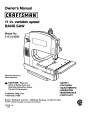
Owner's Manual
11 in. variable speed
BAND SAW
Model No.
315.214500
Save this manual for
future reference.
CAUTION:
Read and
follow all Safety Rules and
Operating Instructionsbefore
first use of this product.
Customer Help Line
1-800-932-3188
Sears, Roebuck and Co., Hoffman Estates,
•
•
•
•
•
•
SAFETY
FEATURES
ADJUSTMENTS
OPERATION
MAINTENANCE
PARTS LIST
IL 60179 USA
Visit the Craftsmanweb page: www.sears.com/craftsman
972000-510
6-98
NRTL
•
Table of Contents ...........................................................................................................................................
2
•
Warranty and Introduction ..............................................................................................................................
2
•
Rules For Safe Operation
...........................................................................................................................
3-5
•
Electrical .........................................................................................................................................................
6
•
Glossary and Product Specifications
7
•
Unpacking, Loose Parts List, and Tools Needed: ..........................................................................................
•
Labels ........................................................................
•
Features .......................................................................................................................................................
•
Assembly .................................................................................................................................................
12-13
•
Adjustments .............................................................................................................................................
13-18
•
Basic Operation .......................................................................................................................................
18-21
•
Maintenance ............................................................................................................................................
21-23
•
Troubleshooting ............................................................................................................................................
•
Exploded View and Repair Parts Ust ......................................................................................................
•
Parts Ordering / Service ...............................................................................................................................
FULL ONE YEAR WARRANTY
.............................................................................................................
ON CRAFTSMAN
_...............................................................................
8
9-10
11
24
26-33
34
BAND SAW
If this CRAFTSMAN" Band Saw fails due to a defect in material or workmanship within one year from the date of
purchase, Sears will repair it, free of charge.
Contact a Sears Service Center for repair.
If this product is used for commemial or rental purposes, this warranty applies only for 90 days from the date of
purchase.
This warranty gives you specific legal rights, and you may also have other rights which vary from state to state.
Sears, Roebuck and Co., Dept. 817WA, Hoffman Estates, IL 60179
Your saw has many features for making cutting
operations more pleasant and enjoyable. Safety,
performance and dependability have been given top
priority in the design of this saw making it easy to
maintain and operate.
,_
_i,
Look for this symbol to point out important
Your safety is involved,
CAUTION: Carefully read through this entire
owner's manual before using your new saw. Pay
close attention to the Rules For Safe Operation,
and all Safety Alert Symbols including Danger,
Warning and Caution. If you use your saw
properly and only for what it is intended, you will
enjoy years of safe, reliable service.
safety
precautions.
It means
attention!i!
WARNING:
The operation of any power tool can result in foreign objects being thrown into your eyes,
which can result in severe eye damage. Before beginning power tool operation, always wear
safety goggles or safety glasses with side shields and a full face shield when needed. We
recommend Wide Vision Safety Mask for use over eyeglasses or standard safety glasses
with side shields, available at Sears Retail Stores.
2
Thepurposeof safetysymbolsis to attractyourattentionto possible
dangers. The safety symbols, and
the explanations with them, deserve your careful attention and understanding. The safety warnings do
not by themselves eliminate any danger. The Instructions
or warnings they give are not substitutes for
proper accident prevention measures.
MEANING
SYMBOL
&
SAFETY
ALERT
SYMBOL:
indicates danger, warning or caution. May be used in conjunction with other symbols or pictographs.
&
DANGER: Failure to obey a safety warning will result in serious injury to yourself or to others.
Always follow the safety precautions to reduce the risk of fire, electric shock and personal injury.
WARNING: Failure to obey a safety warning can result in serious injury to yourself or to others.
Always follow the safety precautions to reduce the risk of fire, electric shock and personal injury.
CAUTION: Failure to obey a safety warning may result in property damage or personal injury to
yourself or to others. Always follow the safety precautions to reduce the risk of fire, electric shock
and personal injury.
Note:
Advises you of information or instructions vital to the operation or maintenance of the equipment.
IMPORTANT
Servicing requires extreme care and knowledge of the system and should be performed only by a qualified
service technician. For service we suggest you retom the tool to your nearest Sears store for repair. Always use
original factory replacement parts when servicing,
&
WARNING:
Do not attempt to operate this tool
until you have read thoroughly and understand
completely all instructions, safety rules, etc.
contained in this manual. Failure to comply can
result in accidents involving fire, electric shock,
or serious personal injury. Save owner's manual
and review frequently for continuing safe
operation, and instructing others who may use
this tool.
READ
ALL
INSTRUCTIONS
KNOW YOUR POWER TOOL. Read the owner's
manual carefully. Learn the saw's applications
and limitations as well as the specific potential
hazards related to this tool•
•
•
GUARD AGAINST ELECTRICAL SHOCK BY
PREVENTING BODY CONTACT WITH
GROUNDED SURFACES. For example; pipes,
radiators, ranges, refrigerator enclosures.
KEEP GUARDS IN PLACE and in good working
order.
REMOVE ADJUSTING KEYS AND
WRENCHES. Get in the habit of checking to see
that hex keys and adjusting wrenches are
removed from tool before turning it on.
•
KEEP THE WORK AREA CLEAN. Cluttered
work areas and work benches invite accidents.
DO NOT leave tools or pieces of wood on the
saw while it is in operation,
•
DO NOT USE IN DANGEROUS
ENVIRON-
MENT. Do not use power tools near gasoline or
other flammable liquids, in damp or wet locations, or expose them to rain. Keep the work
area well lit.
•
KEEP CHILDREN AND VISITORS AWAY. All
visitors should wear safety glasses and be kept a
safe distance from work area. Do not let visitors
contact tool or extension cord while operating.
•
MAKE WORKSHOP CHILD-PROOF with
padlocks and master switches or by removing
starter keys.
•
DO NOT FORCE THE TOOL It will do the job
better and safer at the rate for which it was
designed,
•
USE THE RIGHT TOOL. Do not force the tool or
attachment to do a job it was not designed for.
Don't use it for a purpose not intended.
•
USE THE PROPER EXTENSION CORD. Make
sure your extension cord is in good condition.
RULES
FOR SAFE
OPERATION
(Continued)
When using an extension cord, be sure to use
one heavy enough to carry the current your
product will draw. An undersized cord will cause
a drop in line voltage resulting in loss of power
and overheating. A wire gage size (A.W.G.) of at
least 18 is recommended for an extension cord
binding of moving parts, breakage of parts, saw
stability, mounting and any other conditions that
may affect its operation. A guard or other part
that is damaged must be properly repaired or
replaced by a qualified service technician at a
Sears store to avoid risk of personal injury.
25 feet or less in length. If in doubt, use the next
heavier gage. The smaller the gage number, the
heavier the cord.
DIRECTION OF FEED. Feed work into a blade
or cutter against the direction of rotation of the
blade or cutter only.
INSPECT EXTENSION CORDS PERIODI-
NEVER LEAVE TOOL RUNNING UNATTENDED. TURN THE POWER OFF. Do not
leave tool until it comes to a complete stop.
CALLY and replace if damaged.
DRESS PROPERLY. Do not wear loose clothing,
gloves, neckties, rings, bracelets, or other
jewelry. They can get caught and draw you into
moving parts. Rubber gloves and nonslip footwear are recommended. Also wear protective
hair covering to contain long hair.
USE ONLY CORRECT BLADES. Use the right
blade size, style and cutting speed for the
material and the type of cut. Blade teeth should
point down tov!ard the table.
KEEP BLADES CLEAN, SHARP AND WITH
SUFFICIENT SET. Sharp blades minimize
stalling and kickback.
ALWAYS WEAR SAFETY GLASSES WITH
SIDE SHIELDS. Everyday eyeglasses have only
impact-resistant lenses; they are NOT safety
glasses.
•
PROTECT YOUR LUNGS. Wear a face or dust
mask if the cutting operation is dusty.
M
PROTECT YOUR HEARING. Wear hearing
protection during extended periods of operation.
B
SECURE WORK. Use clamps or a vise to hold
work when practical. It's safer than using your
hand and it frees both hands to operate tool.
DO NOT OVERREACH.
balance at all times.
DO NOT REMOVE THE SAW'S BLADE
GUARDS. Never operate the saw with any guard
or cover removed. Make sure all guards are
operating properly before each use.
M
KEEP HANDS AWAY FROM CUTrlNG
AREA.
Do not hand hold pieces so small that your
fingers go under the blade guard. Do not reach
underneath work or in blade cutting path with
your hands and fingers for any reason.
Keep proper footing and
m
MAINTAIN TOOLS WITH CARE. Keep tools
sharp and clean for better and safer performance. Follow instructions for lubricating and
changing accessories.
M
DISCONNECT ALL TOOLS. When not in use,
before servicing, or when changing attachments,
blades, bits, cutters, etc., all tools should be
disconnected from power supply.
B
AVOID ACCIDENTAL STARTING. Be sure
switch is off when plugging in.
M
USE RECOMMENDED ACCESSORIES. The
use of improper accessories may cause risk of
injury.
_k
WARNING:
Blade coasts after turn off.
•
DO NOT ABUSE CORD. Never yank cord to
disconnect it from receptacle. Keep cord from
heat, oil, and sharp edges.
M
INSPECT TOOL CORDS PERIODICALLY
and if
damaged, have repaired by a qualified service
technician at a Sears store. Stay constantly
aware of cord location and keep it well away
from the moving blade.
M
DO NOT USE TOOL IF SWITCH DOES NOT
TURN IT ON AND OFF. Have defective switches
replaced by a qualified service technician at a
Sears store.
KEEP TOOL DRY, CLEAN, AND FREE FRO•
OIL AND GREASE. Always use a clean cloth
when cleaning. Never use brake fluids, gasoline,
petroleum-based products, or any solvents to
clean tool.
NEVER STAND ON TOOL. Serious injury could
occur if the tool is tipped or if the blade is unintentionally contacted.
M
M
CHECK DAMAGED PARTS. Before further use
ALWAYS SUPPORT LARGE WORKPIECES
of the tool, a guard or other part that is damaged
should be carefully checked to determine that it
will operate properly and perform its intended
function. Check for alignment of moving parts,
while cutting. To minimize risk of blade pinching
and kickback, always support large workpieces.
Saw may slip, walk or slide while cutting large or
heavy beards.
4
RULES
FOR SAFE
OPERATION
(Continued)
•
BEFORE MAKING A CUT, BE SURE ALL
ADJUSTMENTS ARE SECURE.
•
BEFORE CHANGING THE SETUP, REMOVING
COVERS, GUARDS OR BLADE,TURN OFF
THE SAW, AND UNPLUG THE SAW.
•
DO NOT FEED THE MATERIAL TOO QUICKLY.
Do not force the workpiece against the blade.
•
NEVER cut more than one piece at a time. DO •
NOT STACK more than one workpiece on the
saw table at a time.
REPLACEMENT PARTS. All repairs, whether
electrical or mechanical, should be made by a
qualified service technician at a Sears store.
A
WARNING: When servicing, use only identical
Craftsman replacement parts. Use of any other
parts may create a hazard or cause product
damage.
•
NEVER USE IN AN EXPLOSIVE ATMOSPHERE. Normal sparking of the motor could
ignite fumes.
+
AVOID cU'rFING NAILS. Inspect for and
remove all nails from lumber before cutting.
DO NOT OPERATE THIS TOOL WHILE UNDER THE INFLUENCE OF DRUGS, ALCOHOL,
OR ANY MEDICATION.
NEVER TOUCH BLADE or other moving parts
during use.
STAY ALERT AND EXERCISE CONTROL.
Watch what you are doing and use common
sense. Do not operate tool when you are tired.
Do not rush.
NEVER START A TOOL WHEN THE BLADE IS
IN CONTACT WITH THE WORKPIECE.
•
•
•
ALLOW THE MOTOR TO COME UP TO FULL
SPEED before starting a cut.
•
FIRMLY CLAMP OR BOLT your band saw to a
firm, level workbench or table. The most comfortable saw table height is 36 inches or at approximately hip height.
MAKE SURE THE WORK AREA HAS AMPLE
LIGHTING to see the work and that no obstructions will interfere with safe operation BEFORE
performing any work using your saw.
•
AVOID AWKWARD
OPERATIONS
AND HAND
POSITIONS where a sudden slip could cause
your hand to move into the blade. ALWAYS
make sure you have good balance.
ALWAYS TURN OFF SAW before disconnecting
it, to avoid accidental starting when reconnecting
to power supply. NEVER leave the band saw
unattended while connected to a power source.
•
SAVE THESE INSTRUCTIONS.
Refer to them
frequently and use to instruct other users. If you
loan someone this tool, loan them these instructions also.
SAVE THESE INSTRUCTIONS
The blade guides and thrust bearings have been pre-assembled but will require final adjustment before using
your saw. Refer to "ADJUSTING THRUST BEARINGS, BLADE GUIDE SUPPORT, AND BLADE GUIDES"
procedures explained in the ADJUSTMENTS section of the owner's manual.
5
EXTENSION
CORDS
GROUNDING
Use only 3-wire extension cords that have 3-prong
grounding plugs and 3-pole receptacles that accept
the tool's plug. When using a power tool at a considerable distance from the power source, use an extension cord heavy enough to carry the current that the
tool will draw. An undersized extension cord will
cause a drop in line voltage, resulting in a loss of
power and causing the motor to overheat. Use the
chart provided below to determine the minimum wire
size required in an extension cord. Only round jacketed cords listed by Underwriter's Laboratories (UL)
should be used.
Length of Extension Cord
In the event of a malfunction or breakdown, grounding
provides a path of least resistance for electric current
to reduce the risk of electric shock. This tool is
equipped with an electric cord having an equipmentgrounding conductor and a grounding plug. The plug
must be plugged into a matching outlet that is properly
installed and grounded in accordance with all local
cedes and ordinances.
Do not modify the plug provided. If it will not fit the
outlet, have the proper outlet installed by a qualified
electrician. Improper connection of the equipmentgrounding conductor can result in a risk of electric
shook. The conductor with insulation having an outer
surface that is green with or without yellow stripes is
the equipment-grounding conductor. If repair or
replacement of the electric cord or plug is necessary,
do not connect the equipment-grounding conductor to
a live terminal.
Wire Size (A.W.G.)
Up to 25 feet
18
26-100 feet
16
When working with the tool outdoors, use an extension cord that is designed for outside use. This is
indicated by the letters WA on the cord's jacket.
Check with a qualified electrician or service personnel
if the grounding instructions are not completely
understood, or if in doubt as to whether the tool is
properly grounded.
Before using an extension cord, inspect it for loose or
exposed wires and cut or worn insulation.
_,
CAUTION: Keep the cord away from the cutting
area and position the cord so that it will not be
caught on lumber, tools, or other objects during
cutting.
ELECTRICAL
INSTRUCTIONS
Repair or replace a damaged or worn cord immediately.
This tool is intended for use on a circuit that has an
outlet like the one shown in Figure 1. It also has a
grounding pin like the one shown.
CONNECTION
Your Sears Craftsman Band Saw is powered by a
precision built electric motor. It should be connected
to a power supply that is 120 volts, 60 Hz, AC only
(normal household current). Do not operate this tool
on direct current (DC). A substantial voltage drop will
cause a loss of power and the motor will overheat. If
the saw does not operate when plugged into an outlet,
double check the power supply.
GROUNDING
PIN
COVER01FGROUNDED
OUTLETBOX
Fig. 1
6
Bevel Cut
Push Stick
A cutting operation made with an angled table.
A device used to feed the workpiece through the saw
blade during narrow cuffing operations. It helps keep,
the operator's hands well away from the blade.
Crosscut
A cutting operation made across the grain or the width
of the workpiece.
Compound Cut
A compound cut is a cut made using a miter angle
and a bevel angle at the same time.
"
Reeaw
A cutting operation to reduce the thickness of the
workpiece to make thinner pieces.
Resin
FPM
A sticky, sap based substance.
Feet per minute. Used in reference to surface speed
of blade.
Ripping
A cutting operation along the length of the workpiece.
Ferrous Metal
Metal that contains iron; such as steel.
Saw Blade Path
The area directly in line -- over, under, behind, or in
front of the blade. As it applies to the workpiece, that
area which will be, or has been, cut by the blade.
Freehand (for band saw)
Performing a cut without the workpiece properly
supported on the table.
Set
The distance that the tip of the saw blade tooth is bent
(or set) outward from the face of the blade.
Gum
A sticky, sap based residue from wood products.
Kerf
The material removed by the blade in a through cut or
the slot produced by the blade in a nonthrough or
partial cut.
Leading End
The end of the workpiece pushed into the cuffing tool
first.
Nonferrous Metal
Metal that does not contain iron; such as aluminum,
brass, and copper.
Miter Cut
A cutting operation made with the edge of the
workpiece at any angle to the blade other than 90
degrees.
Throw-Back
Throwing of a workpiece in a manner similar to a
kickback. Usually associated with a cause other than
the kerr closing, such as a workpiece being dropped
into the blade, or being carelessly placed in contact
with the blade.
Through Sawing
Any cutting operation where the blade extends
completely through the workpiece.
Workplece
The item on which the cuffing operation is being done.
The surfaces of a workpiece are commonly referred to
as faces, ends, and edges.
Worktable
The surface on which the workpiece rests while
performing a cutting operation.
Blade Width
Blade Length
118 in. to 3/8 in.
56-7/8 in.
Capacities:
Frame to Blade
Under guide
Table Size
Table Tilt
Input
No Load Speed
11 in.
3-1/8 in.
11-1/2 in. x 11-1/2 in.
Overall Dimensions
Net Weight
0 ° - 45 °
120 V, 4.2 amp 60 Hz, AC only
300-3000 FPM
24-1/2 in. x 12-1/2 in. x 24-1/2 in.
28 Ibs.
_i,
•
WARNING: To prevent accidental starting that
could cause possible serious personal injury,
assemble all parts to your saw before connecting
it to power supply. Saw should never be
connected to power supply when you are
assembling parts, making adjustments, installing
or removing blades, or when not in use.
_k
WARNING: If any parts are missing, do not
operate this tool until the missing parts are
replaced. Failure to do so could result in possible
serious personal injury.
•
Do not discard the packing materials until you
have carefully inspected the saw, identified all
parts, and satisfactorily operated your new saw.
Carefully remove all parts from the carton and
place the saw on a level work surface. Separate
and check against the list of loose parts.
Note: If any parts are damaged or missing, do not
attempt to plug in the power cord and turn the switch
on until the damaged or missing parts are obtained
and are installed correctly.
Check all loose parts from the box with the list below. For your convenience when identifying parts, items A-H
below have been drawn actual size. Assemble according to the instructions on the following pages.
B.
Hex Nut (1/4-20) .................................................
3
C.
Wing Nut (1/4-20) ...............................................
1
D. Truss Head Screw (1/4-20 x 5/8 in.) .................. 1
E.
Screw (M5 x 8) ...................................................
1
F. Scale Indicator ....................................................
1
G. Throat Plate ........................................................
1
H. Hex Key (1/8 in.) .................................................
1
I.
Saw Table (not shown) ......................................
1
J.
Owner's
1
Manual (not shown) ............................
__
V
Fig. 2
The following tools (not included) are needed for
assembly and alignment:
• #'2 Phillips Screwdriver
#2 PHILUPSSCREWDRIVE
• Adjustable Wrench
• Small Combination Square
• 5/16 in. Socket or Nut Driver
SMALL
COMBINATION
SQUARE
5116in. SOCKET/NUTDRIVER
Fig. 3
A,
,A WARNING
_ B.
DVERTENCIA|
A WARNING / ADVERTENCIA
Cl
De
Fig. 4
9
The following labels are on the bend saw with locations indicated.
F.
,AWARNING I ADVERTENCIA
G=
H=
Customer Help Line 1-800-932-3188
Fig. 5
10
KNOW
YOUR BAND
SAW
HEX KEY HOLDER
Before attempting to use, familiarize yourself with all
operating features and safety requirements of _;our
Sears Craftsman band saw. See Figure 6.
A hex key holder inside the front cover keeps hex key
conveniently located for blade guide and blade
tracking adjustments.
BLADE
The saw comes with a standard 1/4 in. blade installed.
ON/OFF
BLADE
GUIDES
Blade guides support the blade and keep it from
twisting during operation. An adjustment is necessary
when blades are changed or replaced.
BLADE
GUIDE
KNOB AND LOCK
LEVER
FRONT VIEW OF BAND SAW
The blade guide assembly should just clear the
workpiece while cutting. Use the blade guide knob
and lock lever to adjust the blade guide assembly to
keep the blade from twisting or breaking. Always lock
the upper blade guide assembly in place before
turning on the band saw.
TABLE
KNOB
Your band saw has an easy access On/Off knob with
variable speed. Pull the knob out to turn ON the saw,
and push the knob in to turn OFF the saw. Turn the
the knob to adjust the speed. Place a pad lock in the
lock post next to the knob to lock the sew in the OFF
position.
QUICKRELEASEKNOB
KNOB
-FRONT COVER
LOCK KNOB
POST
Loosening table lock knob allows table to be tilted at
different angles. Tightening knob locks table in place.
ANGLE
ADJUSTMENT
TENSION
COVER
BLADEGUIDE
KNOB
Once the table lock knob has been loosened, use the
angle adjustment knob to tilt or change the angle of
the table. Always tighten the table lock knob before
turning on the saw.
..SAW BLADE
BLADE
SCALE
The scale shows the angle or degree the table is tilted
for bevel cuffing.
TENSION
ADJUSTMENT
KNOB
The tension adjustment knob controls the amount of
blade tension when changing blades and when
making adjustments for various sawing applications.
TRACKING
ADJUSTMENT
BANDSAW
TABLE
EXHAUST
PORT
BACK VIEW OF BAND SAW
TRACKING
ADJUSTMENTSCREW
SCREW
Tracking adjustment screw adjusts to keep the blade
running in the center of the wheels. It is a set screw
located in the center of the frame on the back of your
band saw.
LOCKLEVER
BAND SAW TABLE
BLADEGUIDE
Your band saw has an 11-1/2 in. square, aluminum
saw table with a rack and pinion tilt control for maximum accuracy, It has a red snap in throat plate, and a
miter slot for use with an optional miter gage,
BLADEGUIDE
ASSEM
SAWDUST
EXHAUST PORT
A standard 2-1/4 in. dust exhaust port has been
provided to make dustless cutting possible. The
pickup adapter end of a vacuum hose fits inside the
dust exhaust port with a wedge tit type connection.
COVER
TABS
TABLE LOCK
KNOB
Easy open cover tabs allow the front cover to be
opened for making adjustments. See Figure 13,
DATAPLATE
ANGLEADJUSTMEN'I
KNOB
11
Fig. 6
INSTALLING SCALE INDICATOR
Align the three holes on the table with the three
holes in the angle bracket. Fasten the table to
the angle bracket using the three flat head
screws and three hex nuts.
See Figure 7.
•
Attach the bevel scale indicator to the saw'frame
below the scale using the screw supplied,
•
ANGLEADJUSTMENTKNOB
Assemble the truss head screw and wing nut to
the edge of the table at the end of the slot. Snap
the throat plate in place on the table.
Note: The wing nut goes below the table.
MOUNTING
WORKBENCH
BAND
SAW
TO
See Figure 9.
If the band saw is to be used in a permanent application, we recommend that you secure it in a permanent
location such as a workbench. When mounting the
saw to a workbench, holes should be drilled through
the supporting surface of the workbench using dimensions illustrated.
ANGLEBRACKET
TABLELOCKKNOB
SCALEINDICATOR
SCALE
INSTALLING
THE
Each leg should be belted securely using 5/16 in.
diameter machine screws, lock washers, and
5/16 in. hex nuts (not included). Screw length
should be 1-314 in. plus the thickness of the
bench top.
Fig. 7
TABLE
•
Locate and mark the holes where band saw is to
be mounted.
•
Drill (4) 318 in. diameter holes through workbench.
•
Place band saw on workbench aligning holes in
the frame with holes drilled in the workbench.
•
Insert all four 5116 in. screws and tighten securely with lock washers and hex nuts.
See Figure 8.
•
Slide the table onto the angle bracket from the
beck of the saw to front, with the blade traveling
through the slot in the table,
TRUSSHEAD
SCREW
FLATHEAD
SCREW(S)
Note: All belts should be inserted from the top. Install
the lock washers and hex nuts from the underside of
the bench.
Supporting surface where band saw is mounted
should be examined carefully after mounting to insure
that no movement during use can result. If any tipping
or walking is noted, secure workbench or supporting
surface before beginning cutting operations.
t
3-1/8in.
..........
18 in.
--e
i
e
HEX NUT(S)
5-3/4in.
3/8 in. Dia.
,
12in`
WINGNUT
Fig. 8
\
!
!
I
3-1/8_Lin.[L
3.1/2 in.
!
J
11 in.
"-I
3-1/2in.
Fig. 9
12
CLAMPING
BAND
SAW
TO WORKBENCH
Note: It may be necessary to countersink hex nuts
and washers on bottom side of mounting board.
See Figure 10.
If the band saw is to be used in a portable application,
we recommend that you fasten it permanently to a
mounting board that can easily be clamped to a
workbench or other supporting surface. The mounting
board should be of sufficient size to avoid tipping of •
saw while in use. Any good grade plywood or chipboard with a 3/4 in. thickness is recommended.
MOUNTING
BOARD
Mount saw to board using holes in frame as a
template for hole pattern or the diagram in
Figure 9. Locate and mark the holes where band
saw is to be mounted.
•
Follow last three steps in previous section called
Mounting Band Saw to Workbench.
If lag bolts are used, make sure they are long enough
to go through holes in the saw and material the saw is
being mounted to. If machine bolts are being used,
make sure bolts are long enough to go through holes
in the saw frame, material being mounted to, lock
washers, and hex nuts.
ADJUSTING
BLADE
GUIDE
C-CLAMP(S)
WORKBENCH
Fig. 10
ASSEMBLY
to unlock the blade guide assembly.
See Figures 11 and 12
&
WARNING: To avoid blade contact, adjust the
blade guide assembly to just clear the workpiece,
approximately 1/8 in. Failure to do so could result
in serious personal injury.
The blade guide assembly should be positioned
approximately 1/8 in. above the top surface of the
workpiece being cut. This helps to keep the blade
from twisting or breaking. Adjust from the back of the
band saw.
•
•
Rotate the blade guide knob to position the blade
guide assembly to the desired position. Use a
scrap piece of the same wood you are about to
cut as a guide to set the height of the blade
guide assembly.
•
Lock
to its
guide
band
position in place by returning the lock lever
upward position. Always lock the blade
assembly in place before turning on the
saw.
LOCKLEVER
Push the lock lever that secures the blade guide
assembly counterclockwise or to the left 1/4 turn
POSiTiON)
BLADEGUIDE
BLADEGUIDE
LOCK LEVER
(UNLOCKED
POSITION)
BLADEGUIDE
ASSEMBLY
Fig. 12
Fig. 11
13
INSTALLING
BLADE
AND
ADJUSTING
THE
WARNING: Always wear safety goggles or
safety glasses with side shields to protect your
eyes while uncoiling band saw blades. Failure to
heed this warning could result in a serious eye
injury.
See Figures 13.
&
WARNING: To prevent accidental starting that
could cause possible serious personal injury,
turn off the saw and unplug the saw before
installing or removing blade.
Wearing gloves, carefully uncoil the blade at
arms length. If the new blade was oiled to
prevent rusting, it may need to be wiped to keep
the oil from your workpiece. Carefully wipe in the
same direction the teeth are pointing so the rag
does not catch on the teeth of the saw blade.
From the back of the saw, push the lock lever
counterclockwise or to the left 1/4 turn to unlock
the blade guide assembly. Use the blade guide
knob to position the blade guide assembly about
half way between the table and the frame.
Return the lock lever to its upright locked position. See Figures 11 and 12.
•
Turn the quick release knob counterclockwise or
to the left to release the tension. Turn the tension
adjusting knob counterclockwise or to the left to
lower the upper wheel. See page 15.
Open the front cover of the saw by the cover
tabs.
•
Carefully remove the old blade. The spring on
the upper wheel allows it to be pulled down
slightly to remove the saw blade from the wheel.
•
Slide the new blade into the slot of the table with
the teeth of the blade toward the front of the saw
and facing down toward the table.
Loosen and remove the wing nut and truss head
screw from the table. See Figure 8.
TENSIONADJUSTINGKNOB
QUICK RELEASE KNOB
FRONTCOVER
OPEN
UPPERWHEEL
SAWBLADE
COVERTAB
EXHAUST
LOWERLEFT
WHEEL
SAW BLADE
COVERTAB
EXHAUST
LOWER_GHT
WHEEL
Fig. 13
14
TENSIONADJUSTINGKNOB
Note:The
blade may need to be turned inside out if
the teeth are pointing in the wrong direction. Hold the
blade with both hands and rotate it inward.
TO INCREASE
TENSION
Place the blade through the upper blade guides
and around the upper wheel. Place the blade
around the lower wheel on the left. Work the
blade around the third wheel making sure it goe_
between the lower blade guides. Pull down on
the upper wheel slightly to place the saw blade
on the third wheel, if needed. Slowly turn the
upper wheel to the right or clockwise by hand to
center the blade on the rubber tires.
•
Adjust the blade tension and check or adjust the
blade tracking. See pages 15 and 16.
•
Adjust both upper and lower blade guides and
thrust bearings. See pages 17 and 18.
•
Replace the truss head screw and wing nut.
Tighten securely.
Close the cover of the band saw.
•
ADJUSTING
BLADE
Fig. 15
•
See Figures 14 and 15.
Turn off and unplug the saw.
A
WARNING:
Failure to unplug your saw could
result in accidental starting causing possible
serious personal injury.
Turn the tension adjusting knob (upper, smaller
knob) to the right or clockwise to increase
tension or raise the upper wheel. Turn it to the
left or counterclockwise to decrease tension on
the blade or lower the upper wheel.
Note: Adjustments of the blade tension can be made
at anytime. The quick release knob can be either
released or engaged while making adjustments with
the tension adjusting knob.
TENSION
•
TO DECREASE
TENSION
•
Rotate the quick release knob to the right or
clockwise 1/4 turn to engage tension before
using the band saw.
•
To check the tension, raise the blade guide
assembly all the way up exposing the blade.
•
Pushing the blade to the side with moderate
force, the blade should deflect approximately
1/8 in.
QUICKRELEASEKNOB
Another method of checking the tension has to do
with the sound the blade makes when plucked like a
guitar string.
TO RELEASE
•
TO ENGAGE
Pluck the back straight edge on the coasting side
opposite the blade guides while turning the
tension knob. Sound should be a musical note.
Sound becomes less flat as tension increases.
Sound decreases with too much tension.
Using either method to check tension requires knowing
your band saw and can be developed with practice.
Fig. 14
The tension adjusting knob is on the top of the
saw. Rotate the quick release knob (outer, larger
knob) 1/4 turn to the left or counterclockwise to
release blade tension.
•
Never tension the blade so tight as to completely
compress the spring. The spring can no longer
act as a shock absorber.
Note: Be careful not to over tension the blade. Too
much tension may cause the blade to break. Too little
tension may cause the blade to slip on the wheels.
15
TRACKING
THE
BLADE
If the blade moved away from the front of the
saw, turn the adjustment screw out (to the left or
counterclockwise) while turning the wheel by
hand, until the blade moves forward and rides in
the center of the tire.
See Figure 16.
Note: Blade tension must be properly adjusted before
tracking the blade.
•
Open the front cover of the saw. Slowly turn the
u_per wheel to the right or clockwise by hand
and watch the blade on the upper tire. If the
blade moves away from the center of the tire, the
tracking must be adjusted.
TO ADJUST:
•
Remove 1/8 in. hex key located in the holder
inside the front cover.
•
Insert the 1/8 in. hex key into the tracking adjustment screw located on the back of the saw
behind the upper wheel.
If the blade moved toward the front of the saw
turn the adjustment screw in (to the right or
clockwise) while turning the wheel by hand, until
the blade moves back and rides in the center of
the tire.
•
Check the position of the blade on the other two
tires. The blade should be completely on the
tires. If not, adjust the tracking until the blade is
on all three tires.
•
Rotate the upper wheel by hand in a clockwise
direction for a few more turns. Make sure the
blade stays in the same location on the tires.
Readjust if necessary, until blade is tracking
properly.
Note: The 1/8 in. blade may not track properly in the
center of the wheel. It may be better to track this
blade on the back half of the upper wheel.
•
Replace hex key in holder located inside of the
front cover. Close front cover.
ALIGNING
BLADE
THE
TABLE
SQUARE
TO THE
See Figure 17,
,_
WARNING: To prevent accidental starting that
could cause possible serious personal injury,
turn off the saw and unplug the saw before
making adjustments.
•
From the back of the saw, push the lock lever
counterclockwise or to the left 1/4 turn to unlock
the blade guide assembly.
•
•
Rotate the blade guide knob to move the blade
guide assembly all the way up. Return lock lever
to the upward position to lock assembly in place.
Loosen table lock knob. Place a small combination square on table beside blade.
•
Rotate angle adjustment knob to tilt the table up
or down to align table 90" to blade (0 ° position).
Tighten the table lock knob.
•
Using the 1/8 in. hex key, adjust the zero stop
set screw until the set screw just touches the
frame.
Check squareness of table to blade. Make
readjustments if necessary.
Loosen screw on scale indicator and align red
mark to zero on scale.
Tighten all screws securely.
HEXKEY
_ in.)
Fig. 16
16
To Adjust
LOCK LEVER,,
BLADEGUIDE
•
BLADE GUIDE
ASSEMBLY
•
Move the thrust bearing to within 1/64 in. of the
blade. Tighten the thrust bearing screw securely.
Repeat this procedure on the lower thrust
bearing, located below the table.
Note: The thrust bearing is to support the back edge
of the blade while cutting. The blade should not
contact the bearings when you stop cutting. It is
important that both thrust bearings be adjusted
equally.
TABLE
LOCKKNOB
SCALE
INDICATOR
To Adjust
ANGLI
KNOB
GUIDE
THRUST
SUPPORT,
AND
BEARINGS,
BLADE
BLADE
Blade
Guide
Support
•
Next, adjust the position of the blade guide
support. Loosen the bottom screw on the right
side of the blade assembly using the hex key.
•
Slide the blade guide support on the shaft until
the front edge of the blade guides are about 1164
in. behind the gullet of the blade. Tighten the
screw securely. Repeat this procedure for the
lower blade guide support.
Fig. 17
GUIDES
See Figures 18, 19, and20.
The upper and lower blade guides and thrust bearings
support the band saw blade during cutting operations.
The adjustment of the guides and bearings should be
checked whenever a different blade is installed.
_,
Bearings
Note: The thrust bearing screw is the upper cap
screw located on the right side of the blade guide
assembly. It is the lower cap screw on the right side of
the frame below the table for the lower bearing.
SMALL
COMBINATION
SQUARE
ADJUSTING
Thrust
Adjust the thrust bearings first. Using the 118 in.
hex key, loosen the thrust bearing screw.
Note: The lower blade guide support screw is the top
screw located on the right of the saw frame under the
table. See Figure 19.
WARNING;
To prevent accidental starting that
could cause possible serious personal injury,
turn off the saw and unplug the saw before
making adjustments.
_,
WARNING:
Never operate saw without blade
guard secured in place. To do so could result in
possible serious personal injury.
GUARDREMOVED
BLADEGUIDE
SUPPORTSCREW
BLADE
THRUSTBEARING
SCREW
SCREW
BLADEGUIDE
SCREWS
D
BLADEGUIDE
SCREWS
BLADE GUIDE
SUPPORT SCREW
THRUSTBEARING
LOWER BLADE GUIDE
BLADE GUIDE ASSEMBLY
Fig. 18
17
Fig. 19
To Adjust •lade Guides
Theblade guides help keep the blade
BLADE GUARD REMOVED
FOR CLARIFICATION ONLY
from twisting
and binding. Letting the blade teeth hit the blade
guides while using the band saw will ruin the blade.
The set of teeth and the sharpened edge of teeth
would be damaged by hitting the blade guides. Proper
adjustment of the upper and lower blade guides will ,
prevent this from happening.
•
•
THRUST
Loosen the two blade guide screws that lock the
upper blade guides. Press the two guides evenly
near the sides of the blade leaving about 0.004
in. from the blade. (0.004 is the thickness of a
dollar bill.) Do not pinch the blade. Make sure
one guide is not further away from the blade than
the other. Release the guides and tighten both
screws securely.
THRUST
BEARINGSCREW
BLADEGUIDE
SCREW
BLADEGUIDES
Repeat this prOcedure on the lower blade guides
located under the table. See Figure 19.
Fig. 20
VARIABLE
This band saw is designed to cut wood, wood composition prOducts, plastic, and nonferrous metals (aluminum, brass, copper).
SPEED
See Figure 22.
The variable speed control may be adjusted to the
approximate speeds identified on the On/Off knob
label. Turn the knob clockwise or to the right to
increase speed, up to 3000 FPM (feet per minute).
Turn the knob counterclockwise or to the left to
reduce speed as low as 500 FPM (feet per minute).
_1_ CAUTION: Do not cut ferrous metals (steel, iron)
or hardened steel or serious damage to the saw
could result.
ON/OFF
SCREW
KNOB
See Figure 21.
•
Pull the knob out to turn the saw ON.
Note: The motor will gradually come up to speed after
the saw is turned ON.
•
Push the knob in to turn the saw OFF.
TOINCREASESPEED
PUSHOFF
ON/OFFKNOB
WiTH
VARIABLESPEED
e--
PULLON
ONIOEFKNOB
WITH
VARIABLESPEED
SPEED
Fig. 21
18
Fig. 22
LOCK POST
To preventunauthorized
useofyourbandsaw,we
suggestthatyoudisconnect
it fromthe power dupply
and lock the knob in the OFF position. A padlock with
a shackle of 6 mm or 114 in. diameter may be used.
When the lock is installed and locked, the switch is
inoperable. Store the padlock key in another location.
•
To lock knob in OFF position, install a padlock
through the lock post beside the knob, and lock
the padlock.
•
Use both hands while feeding the work into the
blade. Hold the workplece firmly against the
table. Usa gentle pressure. Do not force the
work, but allow the blade to cut.
•
The smallest diameter circle that can be cut out
is determined by the width of the blade. A 114 in.
wide blade will cut a minimum diameter of
approximately 1-1/2 in. A 1/8 in. wide blade will
cut a minimum diameter of approximately 1/2 in.
•
ON/OFFKNOB
WITH
VARIABLESPEED
Relief cuts are made when an intricate curve (too
small a radius for the blade) is to be cut. A relief
cut is made by cutting through the scrap section
of workplsce to curve in pattern line, then carefully backing blade out. Several relief cuts should
be made for intricate curves, then follow pattern
line as sections are cut off of curve "relieving"
blade pressure.
Avoid Injury from unexpected uw
ment:
LOCKPOST
move-
Put the saw on a firm level surface with plenty of
room for handling and properly supporting the
workpiece.
Make sure table is level and saw does not rock.
Bolt the saw to the support surface to prevent
slipping, walking or sliding during operations like
cutting long, heavy boards.
Turn saw off, lock with padlock, and unplug cord
before moving the saw.
Fig, 2:3
GENERAL
OPERATION
Avoid Injury from Jams, 8111_or thrown
pieces:
A band saw is basically a "curve cutting" machine. It
can also be used for straight-line cuffing operations
such as cross cutting, ripping, mitedng, beveling,
compound cuffing, and resawing. It is not capable of
making inside or non through cuts.
Choose right size and style blade for material
and the type of cut you plan to do.
USE ONLY RECOMMENDED ACCESSORIES,
The use of improper accessories may cause risk
of injury to persons.
For general type scroll cuffing, follow the pattern lines
by pushing and turning the workplece at the same
time. Do not try to turn the workpiece while engaged
in the blade without pushing it or the workpiece could
bind or twist the blade. The blade should cut in the
middle of the pattern line since band saw blades are
thin.
Make sure the blade teeth point downward,
toward -thetable.
Make sure blade guides and thrust bearings are
properly adjusted.
Make sure blade tension is properly adjusted.
•
Always inspect your band saw for proper adjustments before each use.
Make sure table lock knob is tight and no parts
have excessive play.
•
A curved radius cut is best performed by following the pattern line with the blade while turning
the workpiece.
Always adjust the blade guide assembly to just
clear the workpiece to avoid accidental blade
contact, minimize blade breakage and provide
maximum blade support.
19
m
Use extra caution with large, very small or
awkward workpleces:
When saw is running:
Before starting your cut, watch the saw while it
runs. If you experience excessive vibration or
unusual noise, stop immediately. Turn the saw
off, lock with padlock, and unplug the saw. Do
not restart until locating and correcting problem.
Use extra supports (tables, saw horses, bJocks,
etc.)
Never use a person as a substitute for a table
extension, or as additional support for a workpiece that is longer or wider than the basic saw,
table, or to help feed, support or pull the workpiece.
Before freeing any jammed material:
Turn switch OFF.
Wait for all moving parts to stop.
When cutting irregularly shaped workpieces, plan
your work so it will not pinch the blade. For
example, a piece of molding must lay flat on the
table. Workpieces must not twist, rock, or slip
while being cut,
Unplug the saw.
When backing up the workplece, the blade
may bind In the kerf (cut). This is usually
caused by sawdust clogging up the kerr or
because the blade comes out of the guides. If
this happens:
Properly support round material such as dowel
reds, or tubing. They have a tendency to roll
during a cut, causing the blade to "bite." To
avoid this, always use a "V" block or clamp
workpiece to a miter gage.
Turn switch Off.
Wait for all moving parts to stop.
Unplug the saw.
• Cut only one workpiece at a Ume.
Open band saw cover.
• Clear everything except the workpiece and
related support devices off the table before
turning the saw on.
•
Wedge the kerf open with a flat blade screwdriver or wooden wedge.
Turn the upper wheel by hand while backing up
the workpiece.
Plan the way you will hold the workplece
from start to finish:
•
Before removing loose pieces from the table,
turn saw off and walt for all moving parts to
stop.
Do not hand hold pieces so small that your
fingers will go under the blade guard. Keep your
hands away from the blade.
Before leaving the saw:
• Avoid awkward operations and hand positions
where a sudden slip could cause serious injury
from contact with the blade. Never place hands
in path of blade.
Turn switch Off.
Wait for all moving parts to stop.
Lock the knob in the OFF position, using a
padlock to keep children and others not qualified
to use the tool from using the tool.
_1= WARNING: Do not allow familiarity with your
saw make you careless. Remember that a
careless fi'action of a second is sufficient to inflict
severe injury.
Unplug the saw.
Make workshop child-proof. Lock the shop.
20
CHOICE
OF BLADE
AND
TYPESOF BLADES ANDAPPROXIMATESPEEDS
SPEED
Your band saw will cut a wide variety of material
including wood, wood like products, and nonferrous
metals (aluminum, brass, copper).
Note: Inside the front cover of the saw and printed on
page 9 in this manual is a blade size label.
•
Always usa the correct blade for the material
being cut.
•
Use a fine tooth blade for cutting thin workpieces
when a smooth cut is required, when cutting hard
material, or when using lower speeds.
Material
Speed
Wood
2460 FPM
General Purposes
3 in.
Plastic
1230 FPM
General Purposes
1/2 in.
Aluminum
Brass
1130 FPM
Metal Cutting
114 in.
840 FPM
Metal Cutting
114 in.
400 FPM
Metal Cutting
114 in.
Copper
METAL
Blade
Maximum
Thickness
CUTTING
•
Always use a blade that will have at least 2 teeth
in the material at all times.
Many kinds of metals can be cut with your saw. Be
careful not to twist or bend the blades. Do not force. If
•
For best results, use thin, narrow blades for tight
radius work, and thick, wide blades for large
curves and straight cuts.
•
Match the approximate blade speed (FPM) to the
material being cut.
blade heats excessively, use lower speed, ff blade tooth
become filled or clogged when cut_ng soft metals, such
as aluminum, usa a coarsar-tooth blade or lower speed.
We recommend the use of cutting oil when cutting most
soft metals to keep blades cool, increase cuffing action,
and prolongblade life.
_1= CAUTION: Do not cut ferrous metals (steel, iron)
n
or hardened steel or serious damage to the saw
could result.
_i,
_i,
WARNING:
When servicing, usa only identical
Craftsman replacement parts. Use of any other
part may create a hazard or cause product
damage.
GENERAL
LUBRICATION
MAINTENANCE
All of the bearings in this tool are lubricated with a
sufficient amount of high grade lubricant for the life of
the unit under normal operating conditions. Therefore,
no further lubrication is required.
Avoid using solvents when cleaning plastic parts.
Most plastics are susceptible to damage from various
types of commercial solvents and may be damaged
by their usa. Use clean cloths to remove dirt, carbon
dust, etc.
_1,
WARNING: To prevent accidental starting that
could cause possible serious personal injury,
turn off the saw and unplug the saw before
working on the band saw.
TIRES
To properly and safely maintain the wheel tires, the
blade should be removed from the band saw. The
tires should be kept clean. When the tires become
worn they should be replaced.
•
Pitch and sawdust that accumulates on the tires
should be removed with a fine wire brush or a
WARNING:
Do not at any time let brake fluids,
gasoline, petroleum-based products, penetrating
oils, etc. come in contact with plastic parts. They
contain chemicals that can damage, weaken or
destroy plastic.
piece of wood. Do not usa a sharp knife or any
kind of solvent.
Keep your band saw clean.
Remove sawdust from the inside frequently.
Do not allow pitch to accumulate on the table,
blade guides, or thrust bearings. Clean them with
gum and pitch remover.
Apply a thin coat of automobile type wax to the
table top so the wood slides easily while cutting.
Also apply wax to the inside surfaces of the
angle bracket.
21
•
Remove the saw blade, and the worn tires.
Stretch the new tires around each wheel.
•
Reinstall saw blade.
BRUSH
,_,
See Figure 24.
_k
WARNING: To prevent accidental starting that
could cause possible serious personal injury,
turn off the saw, lock knob in the off position, and
unplug the saw before working on the band saw,
MOTOR
Your saw has externally accessible brush assemblies
that should be periodically checked for wear. When
one of the two brushes becomes worn, replace both
brushes.
toward the wheel. The brush should just touch
the wheel.
Carefully pull the brush straight off of the brush
holder to replace the brush. Push the new brush
on the holder until you hear it snap in place.
•
Remove the brush holder screw to replace both
brush and holder.
BRUSH
BRUSHHOLDER
SCREW
BLADE
BRUSHES
See Figure 24.
There is a brush located inside the saw's cover, next
to the lower right wheel. The brush helps protect the
tire and wheel by brushing off saw dust. As the brush
becomes worn, it will need to be adjusted or replaced.
•
Loosen the screw to slide the brush and holder
•
WARNING: To avoid fire or electrocution,
reassemble electric parts with only identical
Craftsman replacement parts. Reassemble
exactly as originally assembled.
•
Unplug your saw.
,_
WARNING:
Failure to unplug your saw could
result in accidental starting causing serious
injury.
•
Remove brush cap with a flat blade screwdriver.
Brush assembly is spring loaded and will push
against the cap as it releases.
•
Remove brush assembly.
•
Check for wear. If one brush is worn down
shorter than 1/4 in., replace both brushes. Do
not replace one side without replacing the other.
•
Reassemble using new brush assemblies. Make
sure curvature of brush matches curvature of
motor and that brush moves freely in brush tube.
•
Make sure brush cap is oriented correctly
(straight) and replace.
•
Tighten brush cap securely. Do not overtighten.
•
Repeat for other brush.
BRUSHHOLDER
Fig. 24
GUIDES
See Figures 18 and 19 on page 17.
•
The blade guides may become rounded and
worn during use. Remove the blade guides and
file or grind flat.
•
Replace the guides when filing or grinding has
worn down guides and they can no longer be
properly secured in place.
MOTOR/ELECTRICAL
•
Frequently vacuum or blow out any sawdust from
the motor.
_1,
WARNING:
If the power cord is worn, cut, or
damaged in any way, have it replaced immediately by a qualified service technician at a Sears
store. Failure to do so could result in serious
personal injury.
Fig. 24
22
DRIVE BELT
See Figures 25, 26, 27, and 28.
,_
WARNING: To prevent accidental starting that
could cause possible serious personal injury,
.turn off the saw, lock the knob in the off position,
and unplug the saw before working on the band,
SaW.
Due to wear or breakage, the drive belt may need to
be replaced. The drive belt is located on the motor
pulley and on the lower right wheel of the band saw.
LOWERRIGHTWHEEL
DRIVEBELT
b LOWERRIGHT
WHEEL
O
Fig. 27
MOTOR
NUTS
•
Remove the worn drive belt by sliding it off the
wheel and then off the motor pulley.
•
Matching grooves, place new drive belt on the
motor pulley and then on the wheel.
Rotate the motor to the left or counterclockwise
from the front of the saw to apply tension to the
drive belt. Using a thumb and finger to squeeze
the belt, it should give about 114 in. Tighten the
three motor nuts.
•
MOTORPULLEY
DRIVEBELT
Note: A drive belt that is too tight may cause increased noise or overload the motor.
Fig. 25
Loosen the three motor nuts and rotate the motor
to the right or clockwise to reduce tension on the
old drive belt.
COUNTERCLOCKWISE
TO TIGHTEN
TO TIGHTEN
DRIVEBELT
CLOCKWISE
TO LOOSEN
TO LOOSEN
DRIVEBELT
Fig. 28
Fig. 26
23
_1
WARNING: For your own safety, turn saw Off, lock knob in the off position, and remove plug from power
source before adjusting or aligning your band saw.
PROBLEM
CAUSE
SOLU_ON
Motor will not run.
1. Problem with On-Off switch or
1. Have worn parts replaced
before using Band Saw again.
power cord.
2. Motor Defective.
2. Do not attempt any repair.
Have repaired by a qualified
service technician at a Sears
store.
Blade does not run in the approximate center of the upper wheel.
1. Not tracking properly.
1. Adjust tracking, See Adjustments section Tracking the
Blade.
Band Saw slows down when
1. Cutting too small a radius.
1. Stop feeding, and back up the
material slightly, until the band
saw speeds up.
2. Dull blade.
2. Replace blade.
1. Too much tension.
1°
cutting.
Blades breaking.
.
.
Saw is noisy when running.
Blade will not cut straight.
Blade guides will not stay in
position,
Kink in blade caused by cutting
too small a radius or turning the
material too fast when cutting.
Thrust bearings scarred or not
rotating,
Adjust tension. See Adjustments section Adjusting Blade
Tension.
,
Use correcLcutting technique.
See section Basic Operation
of the Band Sew.
3. Replace the thrust bearings.
1. Too much blade tension.
1. Adjust blade tension. See
Adjustments section AdJusUng
Blade Tension.
2. Blade guides and backup
bearings are in contact with the
blade.
2.
1. Blade guides and bearings not
properly adjusted.
1.
2. Worn or defective blade.
2. Replace blade.
1. Blade guide screws have
loosened,
1. Tighten blade guide screws
securely.
24
Adjust upper and lower blade
guidesand bearings. See
Adjustments section Adjusting
Thrust Bearings, Blade Guide
Support, and Blade Guides.
Adjust upper and lower blade
guides and bearings. See
Adjustments section Adjusting
Thrust Bearings, Blade Guide
Support, and Blade Guides.
25
CRAFTSMAN
I
BAND
SAW-
MODEL
NO. 315.214500
I
number
in allnumber
correspondence
regarding
_,our BAND
SAW
ordering
parts.
The model
will be found
on a plate
attached
to or
thewhel_
frame.
Alwaysrepair
mention
the model
|
5
4
6
2
19
i
I
!
7
18
16
15
!
8
2O
9
i
12
FIGURE A
26
10
CRAFTSMAN
!
BAND SAW-
MODEL
NO. 315.214500
The model number will be found on a plate attached to the frame. Always mention the model
number in all correspondence regarding your BAND SAW or when ordering repair parts.
SEE BACK PAGE FOR PARTS
ORDERING
]
I
INSTRUCTIONS
PARTS LIST FOR FIGURE A
Key
No.
Part
Number
Description
1
STD541625
**
2
977095-001
3
Quan.
Wing Nut (1/4-20) ..............................................................
1
*
Screw (1/4-20 x 3/4 in. Truss Hd.) ......................................
1
977079-001
*
Screw (1/4-20 x 5/8 in. Socket Hd.) ....................................
1
4
977085-001
*
Screw (1/4-20 x 7/8 in. Flat Hd.) .........................................
3
5
977027-001
Throat Plate ........................................................................
1
6
977028-001
Table ....................................................................................
1
7
977030-001
Table Lock Knob .................................................................
1
8
977092-001
Washer ................................................................................
1
9
977031-001
Spindle ................................................................................
1
10
977093-001
Washer (Shim) ....................................................................
1
11
977086-001
Scale ...................................................................................
1
12
STD541025
** Hex Nut (1/4-20) .................................................................
3
13
977033-001
Angle Adjustment Shaft ......................................................
1
14
977032-001
Angle Bracket ......................................................................
1
15
977105-001
Washer (Shim) ....................................................................
1
16
977029-001
Angle Adjustment Knob ......................................................
1
17
977065-001
Spring ..................................................................................
1
18
STD551025
Washer ................................................................................
1
19
977088-001
Retaining Ring ....................................................................
1
20
820193-005
Hex Key 1/8 in. (Item No. 9-28135) ....................................
1
**
* Standard Hardware Item - May Be Purchased Locally
** Available From Division 98 - Source 980.00
27
CRAFTSMAN
BAND SAW - MODEL NO. 315.214500
11
3
\
5
I
r_
co
5_
7
4
10
8
FIGURE B
3
4
CRAFTSMAN
BAND SAW - MODEL NO. 315.214500
I
SAW
or when
ordering
parts.
The model
number
will repair
be found
on a plate attached to the frame. Always mention the model number in all correspondence regarding your BAND
I
PARTS LIST FOR FIGURE B
Key
No.
Part
Number
Description
1
979861-001
Grommet ........................................................................................................................
1
2
977082-001
Strain Relief ...................................................................................................................
2
3
979865-001
Screw .............................................................................................................................
2
4
980032-001
Washer ...........................................................................................................................
2
5
977055-001
Cord ...............................................................................................................................
1
6
977059-001
Motor (Includes Key Nos. 9 & 10) ..................................................................................
1
7
977016-001
Motor Pulley ...................................................................................................................
1
8
977080-001
Retaining C-Ring ............................................................................................................
1
9
979863-001
Motor Brush ...................................................................................................................
2
10
979862-001
Brush Cap ......................................................................................................................
2
11
979865-001
Screw .............................................................................................................................
3
Quan.
u
i
CRAFTSMAN
BAND SAW - MODEL
NO. 315.214500
14
13
52
10
22
44
9
i
I
Co
O
6O
37
47
4O
3
43
FIGURE
C
38
CRAFTSMAN
BAND SAW - MODEL
NO. 315.214500
PARTS LIST FOR FIGURE C
Key
No.
1
2
3
4
5
6
7
8
9
10
11
12
13
14
15
16
17
18
19
20
21
22
23
24
25
26
27
28
29
30
31
32
33
34
35
Description
Quan.
977071-001
Hand Warning Label .....................................
977037-001
Hinge ............................................................
977098-001
Rivet ..............................................................
977074-001
Warning Label ...............................................
977002-001
Front Cover ...................................................
977001-001
Switch Knob ..................................................
977195-001
Knob Label ....................................................
977188-001
On/Off Label .................................................
977186-001
Logo Plate .....................................................
977039-001
Lock Post ......................................................
977198-001
Hex Nut .........................................................
977199-001
Washer .........................................................
977083-001
Screw ............................................................
977007-001
Circuit Board Cover ......................................
980032-001
Star Washer ..................................................
979865-001
Screw ............................................................
977008-001
Circuit Board ................ i................................
977057-001
Cam ..............................................................
977010-001
Quick Release Knob .....................................
977009-001
Tension Adjustment Knob ............................
977081-001
Pin .................................................................
977040-001
Cover Latch ..................................................
977014-001
Frame ............................................................
977015-001
Adjustment Shaft ..........................................
977197-001
Spring ...........................................................
977189-001
Tension/Tracking Label ................................
977079-001
Tracking Screw .............................................
STD861008 ** Washer .........................................................
977069-001
Lock Label ....................................................
STD541031 ** Hex Nut .........................................................
STD852008 ** Spring Washer ..............................................
977060-001
Indicator ........................................................
979865-001
Screw ............................................................
977090-001
* Screw (Hex Cap) ..........................................
977186-001
Data Plate .....................................................
*
_.
Pad
Number
Standard Hardware Item -- May Be Purchased Locally
*** Available
1
2
8
1
1
1
1
1
1
1
1
1
8
1
1
1
1
1
1
1
1
2
1
1
1
1
1
3
1
3
4
1
7
4
1
Key
No.
36
37
38
39
40
41
42
43
44
45
46
47
48
49
50
51
52
53
54
55
56
57
58
59
60
61
62
63
64
66
66
67
68
69
70
71
Pad
Number
Description
Quan.
STD652005 ** Spring Washer ..............................................
4
977091-001
Lock Nut ........................................................
1
977036-001
Base ..............................................................
1
STD835020 ** Hex Bolt ........................................................
2
***
Saw Blade .....................................................
1
977080-001
Retaining 'C' Ring .........................................
3
977196-001
Washer (Shim) ..............................................
6
977038-001
Bearing Bushing ...........................................
3
977004-001
Tire ................................................................
3
977035-001
Drive Belt ......................................................
1
977034-001
Drive Wheel ..................................................
1
. 977097-001
Thrust Bearing ..............................................
1
977023-001
Bearing Pin ...................................................
1
977024-001
Blade Guide ............................................ ,..... 1
977020-001
Blade Guide Support ....................................
1
977026-001
Blade Guide ..................................................
1
977011-001
Wheel Shaft ..................................................
3
STD840610 ** Hex Nut ........................ _............................... 1
STD652006 ** Spring Washer ..............................................
5
979864-001
Brush Holder .................................................
1
977047-001
Brush .............................................................
1
979866-001
Wire Cover ....................................................
1
STD641110 ** Hex Nut .........................................................
3
STD651010 ** Washer .........................................................
3
977005-001
Wheel ............................................................
2
977006-001
Cable Clamp .................................................
2
977041-001
Cord ..............................................................
1
97986!-001
Grommet .......................................................
1
977013-001
Upper Wheel Support ...................................
1
977012-001
Upper Wheel Bracket ...................................
1
STD512503 ** Screw ............................................................
4
Blade Selection Label. .................................. 1
980035-001
977042-001
Wire Cover Plate ..........................................
1
980198-001
Rubber Pad ...................................................
4
980064-001
Washer .........................................................
4
980196-001
Screw ............................................................
4
** Available From Division 98 - Source 980.00
at your nearest Seers Retail Store.
,
CRAFTSMAN
BAND SAW - MODEL NO. 315.214500
17
16
9
15
14
13
8
12
11
GO
PO
5
3
4
3
3
2
FIGURE D
I
CRAFTSMAN
BAND SAW - MODEL NO. 315.214500
The model
SAW
or when
number
ordering
will repair
be found
parts.
on a plate attached to the frame. Always mention the model number in all correspondence regarding your BAND
J
PARTS LIST FOR FIGURE D
CO
Co
Key
Part
No.
Number
Description
1
977026-001
Blade Guide ...................................................................................................................
1
2
977020-001
Blade Guide Support ......................................................................................................
1
3
977090-001
Screw (10-32 x 1/2 in. HexCap)
4
4
977025-001
Blade Guard ...................................................................................................................
5
977024-001
Blade Guide ...................................................................................................................
6
977097-001
Thrust Bearing .........................................................................................................
7
977023-001
Bearing Pin ....................................................................................................................
8
977096-001
Bolt..............................................................................................
I
9
977022-001
Blade Guard Support .....................................................................................................
1
10
977106-001
Screw (10-24 x 3/8 in. Pan Hd.) .....................................................................................
2
11
977021-001
Pinion .............................................................................................................................
1
12
977019-001
Cam ................................................................................................................................
1
13
977018-001
Lock Lever .....................................................................................................................
1
14
977017-001
Blade Guide Knob ..........................................................................................................
1
15
977066-001
Spring .............................................................................................................................
1
16
977087-001
Washer (M6) ..................................................................................................................
1
17
STD541425
Lock Nut (1/4-20) ...........................................................................................................
1
Owner's Manual .............................................................................................................
1
972000-510
*
**
* Standard Hardware Item -- May Be Purchased Locally
,
Quan.
...................................................................................
1
1
,,.... 1
1
** Available From Division 98 - Source 980.00
,_
For in-home major brand repair service:
Call 24 hours a day, 7 days a week
1-800-4-MY-Home s" (1-800-469-4663)
Para pedir servicio de reparacibn
a domicilio
- 1-800-676-5811
In Canada for all your service and parts needs call
- 1-800-665-4455
Au Canada pour tout le service ou les pieces
For the repair or replacement
parts you need:
Call 7 am - 7 pro, 7 days a week
1-800-366-PART
Para ordenar
(1-800-366-7278)
piezas con entrega a domicilio - 1-800-659-7084
For the location of a Sears Parts and Repair Center in your area:
Call 24 hours a day, 7 days a week
1-800-488-1222
For information on purchasing a Sears Maintenance Agreement
or to inquire about an existing Agreement:
Call 9 am - 5 pm, Monday - Saturday
1-800-827-6655
I
The Service Side of Sears"