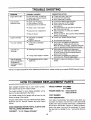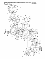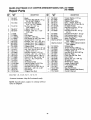
1
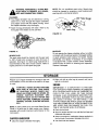
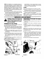
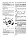
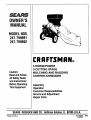
OWNER'S
MANUAL
MODELNOS.
247.799891
247.799892
CRRFTSMRN
Caution:
ReadandFollow
AllSafetyRules
andInstructions
BeforeOperating
ThisEquipment
5 HORSEPOWER
3 CUTTING STAGE
MULCHING AND BAGGING
CHIPPER-SHREDDER
Assembly
Operation
Customer Responsibilities
Service and Adjustment
Repair Parts
SEARS,ROEBUCKAND CO., HoffmanEstates, IL 60195 U.S.A.
)rinted in U.S.A.
770-7924H
(R920820)
9/92
SAFETY RULES
_
SAFETY
INSTRUCTIONS.
WARNING:
TO REDUCE
PERSONAL
INJURY.
FAILURE
TO COMPLY
WITH THE
THE POTENTIAL
FOR ANY INJURY,
TRAINING
• Read this owner's manual carefully in its entirety before
attempting to assemble or operate this machine. Be completely familiar with the controls and the proper use of this
machine before operating it. Keep this manual in a safe
place for future and regular reference and for ordering
replacement parts.
• Children must never be allowed to operate this equipment.
• No one should operate this unit while intoxicated or while
taking medication that impairs the senses or reactions.
• This equipment should never be operated in the vicinity
of children, pets or other persons.
• Never run your machine in an enclosed area as the
exhaust from the engine contains carbon monoxide, which
is an odorless, tasteless and deadly poisonous gas.
• Never place your hands or any part of your body or clothing inside the feeding chamber, discharge chute, or near
any moving part while the machine or engine is running.
• If it is necessary for any reason to inspect or repair the
feeding chamber or any part of the machine where a moving part can come in contact with your body or clothing,
stop the machine, allow it to cool, disconnect the spark
plug wire from the spark plug and move it away from the
spark plug before attempting such inspection or repair.
PREPARATION
• Wear safety glasses provided with your unit while operating the chipper-shredder to prevent injury from any material which may be ejected out of the openings.
• Wear proper apparel. Avoid wearing loose fitting clothing.
Wear gloves when handling material.
• HANDLE GASOLINE WITH CARE as it is an extremely
flammable fuel.
• Check the fuel before starting the engine. Do not fill the
fuel tank indoors, while the engine is running, or while the
engine is still hot. Turn the unit off and let the engine cool
before refueling.
• Fuel your chipper-shredder
in a clean area. Do not
smoke while refueling.
• Fuel tank cap must be secure at all times except during
refueling.
• Avoid spilling gasoline or oil. Wipe the unit clean of any
spilled fuel or oil.
• Store fuel and oil in approved containers, away from heat
or open flame, and out of reach of children.
• This machine should be operated only upon a level surface.
• Assure that all screws, nuts and bolts and other fasteners
are properly secured.
OPERATION
• When feeding shreddable material into this equipment,
be extremely careful that pieces of metal, rocks, bottles,
cans or other foreign objects are not included. Personal
injury or damage to the machine could result.
•
•
•
•
•
•
•
•
•
•
INSTRUCTIONS
COMPLY
WITH
If the cutting mechanism strikes any foreign object or if
your machine should start making an unusual noise or
vibration, immediately stop the engine, disconnect the
spark plug wire from the spark plug and move it away
from the spark plug. Allow the machine to stop and take
the following steps:
Inspect for damage.
Replace or repair any damaged parts.
Check for any loose parts and tighten to assure continued safe operation.
The engine must be kept clean of debris and other accumulations.
Do not allow an accumulation of processed material to
build up in the discharge area as this will prevent proper
discharge and can result in kick-back from feed opening.
Never place your hands or any other part of your body or
clothing inside the feeding chamber, discharge chute or
near any moving part while the engine is running.
Keep all guards and deflectors in place and in good working condition to assure continued safe operation.
Always stand clear of the discharge area when operating
this machine.
Keep your face and body back from the feed opening to
avoid accidental bounce back of any material.
Do not over-reach. Keep proper balance and footing at all
times.
The engine governor settings on your machine must not
be altered, changed, or tampered with. The governor
controls the maximum safe operating speeds and protects the engine and all moving parts from damage
caused by overspeed.
Do not transport machine while engine is running.
Do not operate engine if air cleaner or cover directly over
carburetor air intake is removed, except for adjustment.
Removal of such parts could create a fire hazard.
MAINTENANCE AND STORAGE
• When this equipment is stopped for servicing, inspection,
storage or to change an accessory, make sure the spark
plug wire is disconnected from the spark plug and moved
away from the spark plug. The machine should be
allowed to cool down before making such inspection,
adjustments, service, etc. Maintain your machine with
care and keep it clean for the best and continued safe
operation.
• Do not use flammable solutions to clean the air filter.
• When not in use, your machine should be stored out of
the reach of children. Keep where gasoline fumes will not
reach an open flame or spark. For long periods of storage, refer to the "Storage" section of this manual.
I
&
MAY RESULT
IN
THE FOLLOWING
LOOK FOR THIS SYMBOL TO POINT OUT J
IMPORTANT SAFETY PRECAUTIONS. ITJ
MEANS--ATTENTION!!! BECOME ALERT!!!J
YOUR SAFETY IS INVOLVED.
I
I
2
CONGRATULATIONS
on your purchase of a Sears
Craftsman Chipper-Shredder. It has been designed, engineered and manufactured to give you the best possible
dependability and performance.
Should you experience any problem you cannot easily remedy, please contact your nearest Sears Service Center/
Department in the United States. We have competent, welltrained technicians and the proper tools to service or repair
this unit.
Please read and retain this manual. The instructions will
enable you to assemble and maintain your chipper-shredder
properly. Always observe the "SAFETY RULES."
PRODUCT SPECIFICATIONS
Horsepower:
5.0
Displacement:
12.57 cu. in.
Fuel Capacity:
3 Quarts
(Unleaded)
Spark Plug (Gap .030 in.):
Champion
J19LM (or
Equivalent)
MODEL
NUMBER
Magnetron ® Ignition Air Gap:
SERIAL
NUMBER
DATE OF
PURCHASE
MAINTENANCE
AGREEMENT
A Sears Maintenance Agreement is available on this
product. Contact your nearest Sears store for details.
THE MODEL AND SERIAL NUMBERS WILL BE FOUND
ON A LABEL ATTACHED TO THE FRAME OF THE
CHIPPER-SHREDDER.
YOU SHOULD RECORD BOTH SERIAL NUMBER AND
DATE OF PURCHASE AND KEEP IN A SAFE PLACE
FOR FUTURE REFERENCE.
CUSTOMER
.0125 in.
WARNING: This unit is equipped with an internal combustion engine and should not be used on or near any unimproved forest-covered, brush-covered or grass-covered land
unless the engine's exhaust system is equipped with a
spark arrester meeting applicable local or state laws (if any).
If a spark arrester is used, it should be maintained in effective working order by the operator.
RESPONSIBILITIES
• Read and observe the safety rules.
• Follow a regular schedule in maintaining, caring for
and using your chipper-shredder.
• Follow the instructions under "Customer Responsibilities" and "Storage" sections of this Owner's
Manual.
In the State of California
the above is required by law
(Section 4442 of the California Public Resources Code).
Other states may have similar laws. Federal laws apply on
federal lands. A spark arrester for the muffler is available
through your nearest Sears Authorized Service Center (See
the REPAIR PARTS section of this manual.)
WARRANTY
ONEYEAR LIMITED WARRANTYON CRAFTSMANGAS CHIPPER-SHREDDER
For one year from the date of purchase, when this Craftsman Chipper-Shredder is maintained, lubricated and
tuned up according to the instructions in the owner's manual, Sears will repair, free of charge, any defect in
material and workmanship.
If this Craftsman Chipper-Shredder
days from the date of purchase.
is used for commercial or rental purposes, this warranty applies for only 30
This warranty does not cover:
• Expendable items which become worn during normal use, such as blades, chipper blades, flails, air cleaners,
spark plugs and catcher bags.
• Repairs necessary because of operator abuse or negligence, including bent crankshafts and the failure to
maintain the equipment according to the instructions contained in the owner's manual.
WARRANTY SERVICE IS AVAILABLE BY RETURNING THE CRAFTSMAN CHIPPER-SHREDDER
TO THE
NEAREST SEARS SERVICE CENTER/DEPARTMENT
IN THE UNITED STATES. THIS WARRANTY
APPLIES ONLY WHILE THIS PRODUCT IS IN USE IN THE UNITED STATES.
This warranty gives you specific legal rights, and you may also have other rights which may vary from state to
state.
SEARS, ROEBUCK AND CO., D/817WA, Hoffman Estates, IL 60195
3
TABLE OF CONTENTS
SAFETY RULES .........................................................
2
PRODUCT SPECIFICATIONS ................................... 3
MAINTENANCE AGREEMENT .................................. 3
CUSTOMER RESPONSIBILITIES ............................. 3
WARRANTY ...............................................................
3
INDEX .........................................................................
4
ASSEMBLY ................................................................
5
OPERATION ...........................................................
6-9
CUSTOMER RESPONSIBILITIES ........................ 9-11
STORAGE ..........................................................
11, 12
SERVICE AND ADJUSTMENT ........................... 12-14
TROUBLE SHOOTING ............................................. 15
PARTS ORDERING/SERVICE ................................. 15
REPAIR PARTS--CHIPPER-SHREDDER
........ 16, 17
REPAIR PARTS--ENGINE ................................. 18-21
INDEX
A
O
Oil ...............................................................................
8
Operating Tips ............................................................
7
R
Repair/Replacement Parts .................................. 16-21
Responsibilities, Customer ................................ 3, 9-11
S
Safety Rules ...............................................................
2
Sharpening .........................................................
12, 13
Spark Plug ................................................................
11
Specifications ..............................................................
3
Storage ...............................................................
11, 12
T
Table of Contents .......................................................
4
Adjustments:
Carburetor .......................................................
13, 14
Engine Speed .......................................................
14
Assembly Instructions:
Catcher Bag ............................................................
5
Chute Deflector .......................................................
5
C
Catcher Bag ................................................................
5
Controls ......................................................................
6
Customer Responsibilities ................................. 3, 9-11
E
Engine:
Lubrication ............................................................
10
Maintenance ...................................................
10, 11
Starting ...............................................................
8, 9
Stopping ..................................................................
7
Storage ...........................................................
11, 12
F
Fuel .............................................................................
8
L
Lubrication ................................................................
10
M
Maintenance:
Agreement .............................................................
Schedule .................................................................
3
9
Engine .............................................................
10, 11
Chipper-Shredder ................................................
10
4
Trouble Shooting ......................................................
U
15
Unclogging ................................................................
Unpacking ...................................................................
W
Warranty ....................................................................
12
5
3
ASSEMBLY
INSTRUCTIONS
TOREMOVE
CHIPPER-SHREDDER
FROMCARTON
IMPORTANT: This unit is shipped WITHOUT GASOLINE or OIL. After assembly, see operation section of
this manual for proper fuel and engine oil recommendations.
Cut the corners of the carton. Remove all packing
inserts. Roll chipper-shredder out of the carton. Make
certain all parts, literature and the safety glasses have
been removed before the carton is discarded.
NOTE: To determine right and left hand sides of your
chipper-shredder, stand behind and face the hopper
(engine is at the front of the unit).
Your chipper-shredder
has been completely assembled at the factory, except for the chute deflector and
the catcher bag. A pair of safety glasses are also
included in the carton.
TOOLS REQUIRED FOR ASSEMBLY
(2) 7/16" or Adjustable Wrenches
HOWTO SET-UPYOUR CHIPPER-SHREDDER
(Inside.
Hin(
&
Bolt
Chute
Deflector
MAKE CERTAIN
THE SPARK PLUG
WIRE IS DISCONNECTED AND MOVED
AWAY
FROM
THE SPARK
PLUG
BEFORE ASSEMBLING THE CHIPPERSHREDDER,
ATTACHING THE CHUTE DEFLECTOR
• Remove the hand knobs and cupped washers from
each side of the discharge opening on the left side
of the shredder.
Hex
Nut
• Remove the hex lock nut, two spacers and hex bolt
from inside the hinge on top of the discharge opening. Do not remove one spacer from the hex bolt.
Knob
• Place the chute deflector in position on the discharge opening. Insert bolt through hinge on chute
deflector and housing (spacer fits inside hinge).
FIGURE 1,
• Place second spacer over the hex bolt, inside the
other part of hinge. Secure with hex lock nut.
Tighten securely.
• Secure both sides of the chute deflector to the
housing using hand knobs and cupped washers
(cupped side of washers go against chute deflector).
\
ATTACHING THE CATCHER BAG
Your chipper-shredder is equipped with a catcher bag
to catch the shredded material.
Drawstrin
Catcher
• To attach bag, place bag opening over the chute
deflector so it completely covers chute opening.
Depress plunger on drawstring, pull on drawstring
until bag is tight around chute opening. Release
_plunger
to lock it into position. See figure 2.
FIGURE 2.
5
OPERATION
KNOW YOUR CHIPPER-SHREDDER
READ THIS OWNER'S MANUAL AND SAFETY RULES BEFORE OPERATING YOUR CHIPPER-SHREDDER.
Compare the illustrations with your chipper-shredder to familiarize yourself with the location of various controls
and adjustments. Save this manual for future reference.
Hopper
31y
Chipper
Chute
Chute
Deflector
Lever
Control
Catcher
Bag
Starter
Handle
FIGURE 3.
MEETS ANSI SAFETYSTANDARDS
Sears chipper-shredders
conform to the safety standards of the American National Standards Institute.
OPERATINGCONTROLS(See
figure 3)
CHOKE LEVERmUsed
to enrich the fuel mixture in
the carburetor when starting a cold engine.
STARTER
engine.
HANDLEmUsed
to manually
THRO'I-FLE CONTROL--Controls
stops the engine.
engine speed and
start the
BEFORE USING YOUR CHIPPER-SHREDDER,
AGAIN REFER TO THE "SAFETY
PAGE 2 OF THIS MANUAL. ALWAYS BE CAREFUL.
RULES" AS SHOWN ON
The operation of any chipper-shredder can result in foreign objects being thrown into
the eyes, which can result in severe eye damage. Always wear the safety glasses provided with the chipper-shredder or eye shields before chipping or shredding, or while
performing any adjustments or repairs. We recommend Wide Vision Safety Mask for
over spectacles or standard glasses available at Sears Retail or Catalog Stores.
TO STOP ENGINE
No Larger
1/2" Diameter
(Recommended)
Or 1" Diameter
(Maximum)
• Move throttle control lever to OFF position. See figure 4.
• Disconnect spark plug wire and move away from
spark plug to prevent accidental starting while
equipment is unattended.
Hopper
Assembly
Tt
Control
FIGURE 5.
FIGURE 4.
• Bulky material, such as stalks or heavy branches,
up to 3" in diameter, should be fed into the chipper chute. See figure 6.
WARNING: MAKE CERTAIN THE CHIP-
HOW TO USE YOUR CHIPPER-SHREDDER
Do not attempt to shred or chip any material other
than vegetation found in a normal yard (i.e., branches,
leaves, twigs, etc.).
WARNING:
,_
_1)
NOT
ER IN
CHUTE
USE. DOOR
DISCHARGES
MATERIALS
ERABLE VELOCITY.
KEEP WITH
AWAYCONSIDFROM
THE AREA
AROUND
THE CHUTE
DEFLECTOR.
ALWAYS
STOP
THE
ENGINE AND DISCONNECT THE SPARK
PLUG WIRE WHEN
REMOVING
OR
ATTACHING THE BAG, WHEN CHANGING
CONTAINERS OR WHEN REMOVING THE
SHREDDED MATERIAL. WEAR SAFETY
GLASSES
AND GLOVES WHENEVER
USING YOUR CHIPPER-SHREDDER.
The chipper-shredder
methods of operation.
IS CLOSED
WHEN
THE CHIPPER-SHREDDER
3" Maximum
Diameter
is designed for two different
• Leaves and small branches up to 1/2" diameter
(recommended) or 1" diameter (maximum) can be
fed into the hopper assembly. See figure 5. If it
becomes necessary to push material into the chipper-shredder,
use a small diameter stick--NOT
YOUR HANDS. The stick should be small enough
that it will be ground up if gets into the impeller
assembly.
Chipper
Chute
FIGURE 6.
IMPORTANT: There is a flail screen located inside
the housing in the discharge area. If the flail screen
becomes clogged, remove and clean as instructed in
the Service and Adjustments section. For best performance, it is important to keep the shredding blade
and the chipper blades sharp. If the composition of
the material being discharged changes (becomes
stringy, etc.) or if the rate at which the material is discharged slows clown considerably, it is likely that the
shredding blade and/or chipper blades are dull and
need to be sharpened or replaced. Refer to Service
and Adjustments section.
WARNING:
DO NOT PUT MATERIAL
LARGER THAN 1/2" IN DIAMETER (RECOMMENDED)
or 1" DIAMETER
(MAXIMUM) INTO THE HOPPER ASSEMBLY.
MATERIAL UP TO A MAXIMUM OF 3" IN
DIAMETER
MATERIAL
MAY BE FED
INTO THE CHIPPER CHUTE. DO NOT
ATTEMPT
TO SHRED OR CHIP ANY
MATERIAL LARGER THAN 3" IN DIAMETER. PERSONAL INJURY OR DAMAGE
TO THE MACHINE COULD RESULT.
7
GASAND OIL FILL-UP
OIL
Only use high quality detergent oil rated with API service classification SG. Select the oil's viscosity grade
according to your expected operating temperature.
Colder
_
32°F
m
Warmer
NOTE: Although multi-viscosity oils (5W30, 10W30,
etc.) improve starting in cold weather, these multiviscosity oils will result in increased oil consumption
when used above 32°F. Check your oil level more frequently to avoid possible engine damage from running low on oil.
• Fill engine with oil as follows. Remove oil fill dipstick. See figure 7. With chipper-shredder
level,
use a funnel to fill engine with oil to FULL mark on
dipstick. Capacity is approximately 1-1/4 pints. Be
careful not to overfill. Tilt chipper-shredder toward
the left (from behind the hopper), then re-level.
Check oil level. Refill to FULL mark on dipstick if
necessary. Replace dipstick and tighten.
Check the fuel level periodically to avoid running out
of gasoline while operating the chipper-shredder.
If
the unit runs out of gas as it is shredding or chipping,
it may be necessary to unclog the unit before it can be
restarted. Refer to "Removing the Flail Screen" in
Service and Adjustment section.
WARNING: EXPERIENCE INDICATES THAT ALCOHOL BLENDED FUELS (CALLED GASOHOL OR
USING ETHANOL OR METHANOL) CAN ATTRACT
MOISTURE WHICH LEADS TO SEPARATION AND
FORMATION
OF ACIDS DURING
STORAGE.
ACIDIC GAS CAN DAMAGE THE FUEL SYSTEM
OF AN ENGINE WHILE IN STORAGE. TO AVOID
ENGINE
PROBLEMS,
THE
FUEL
SYSTEM
SHOULD BE EMPTIED OR TREATED WITH FUEL
STABILIZER
BEFORE STORAGE FOR 30 DAYS
OR LONGER. USE FRESH FUEL NEXT SEASON.
SEE "STORAGE"
SECTION FOR ADDITIONAL
INFORMATION.
NEVER USE ENGINE OR CARBURETOR CLEANER PRODUCTS IN THE FUEL TANK OR PERMANENT DAMAGE MAY OCCUR.
Oil
Fill
Dipstick
Spark Plug,
Wire and Boot
Muffler
Fuel
Tank
Oil
Dipstick
Drain
FIGURE
7.
GAS
• Remove fuel cap and fill fuel tank with about 3
quarts of clean, fresh, lead-free grade automotive
gasoline. DO NOT use Ethyl or high octane gasoline. Be certain container is clean and free from
FIGURE 8.
rust or foreign particles. Never use gasoline that
may be stale from long periods of storage in the
container. Replace fuel cap.
TO STARTENGINE
_
1/2 INCH OF TOP OF FUEL TANK TO
WARNING: DO NOT FILL CLOSER THAN
PREVENT SPILLS AND TO ALLOW FOR
FUEL EXPANSION.
IF GASOLINE
IS
ACCIDENTLY SPILLED, MOVE CHIPPERSHREDDER
AWAY FROM AREA OF
SPILL. AVOID CREATING ANY SOURCE
OF IGNITION UNTIL GASOLINE VAPORS
HAVE DISAPPEARED.
WARNING:
_b
BE SURE NO ONE OTHER
THAN
THE CHIPPER-SHREDDER
OPERATOR
IS STANDING
NEAR THE
WHILE
STARTING
OR OPERATING.
DO NOT
OPERATE THIS CHIPPER-SHREDDER
UNLESS THE CHUTE DEFLECTOR HAS
BEEN PROPERLY
INSTALLED
AND IS
SECURED WITH THE HAND KNOBS.
• Attach spark plug wire and rubber boot to spark
plug if necessary. See figure 8.
Choke
•
Place the throttle control lever in FAST position.
See figure 9.
• Move choke lever to CHOKE position.
)
• Grasp starter handle (see figure 9) and pull rope
out slowly until engine reaches start of compression cycle (rope will pull slightly harder at this
point). Let the rope rewind slowly.
OFF
RThroffie
NOTE: A noise will be heard when finding the start of
the compression cycle. This noise is caused by the
flails and fingers which are part of the shredding mechanism falling into place, and should be expected. In
addition, the flails and fingers will be noisy after the
engine is started, until the impeller reaches full speed.
•
Pull rope with a rapid, continuous, full arm stroke.
Keep a firm grip on start handle. Let rope rewind
slowly. Do not let starter handle snap back against
starter.
•
Repeat preceding two instructions
until engine
fires. When engine starts, move choke lever on
engine halfway between CHOKE and RUN.
MAINTENANCE
Control--
•
_
!
"
• Move throttle control to IDLE position for a few minutes warm-up. Move choke lever to RUN position
as engine warms up.
NOTE: In order to idle smoothly, a new engine may
require 3 to 5 minutes running above slow idle speed.
Idle speed has been adjusted to be correct after this
break-in period.
TO STOP ENGINE
• Move throttle control lever to OFF position. See figure 4.
• Disconnect spark plug wire and move away from
spark plug to prevent accidental starting while
equipment is unattended.
RESPONSIBILITIES
SCHEDULE
FILL IN DATES
AS YOU COMPLETE
REGULAR SERVICE
/ _#"
Oil Pivot Points
O
_-
FIGURE 9.
NOTE" If engine does not fire after three attempts,
move choke lever halfway between CHOKE and RUN
position and try again. See figure 9.
CUSTOMER
IDLE__FAST
4
Clean Shredder
_J
o,.
Check Engine Oil
Change Engine Oil
_i
_J
_J
Service Air Cleaner
_J
Clean Engine Cylinder
q
_/
Spark Plug
q
_/
i
Muffler
CHECK
9
SERVICE DATES
GENERALRECOMMENDATIONS
AIR CLEANER
The air cleaner prevents damaging dirt, dust, etc.,
from entering the carburetor and being forced into the
engine and is important to engine life and performance.
WARNING: ALWAYS STOP THE ENGINE
AND DISCONNECT
THE SPARK PLUG
WIRE
BEFORE
PERFORMING
ANY
MAINTENANCE OR ADJUSTMENTS.
• Periodically
are tight.
•
Never run your engine without
pletely assembled.
check all fasteners and be sure they
To Service Air Cleaner:
Follow the Maintenance
page.
Schedule
on previous
Service pre-cleaner after every 25 hours of use, or at
least once a season. Service cartridge every 100
hours of use, or at least once a season. Service precleaner and cartridge more often under dusty conditions.
CHIPPER-SHREDDER
Loosen screw and remove cover.
LUBRICATION
Lubricate the pivot points on the chute deflector and
chipper chute once a season using a light oil.
To service pre-cleaner, wash in liquid detergent
and water. Squeeze dry in a clean cloth. Saturate
in engine oil. Squeeze in a clean, absorbent cloth
to remove all excess oil. If pre-cleaner is very dirty,
replace it.
ENGINE
• To service cartridge, clean by tapping gently on a
flat surface. If very dirty, replace. Do not oil cartridge.
ENGINE OIL
Only use high quality detergent oil rated with API service classification SG. Select the oil's viscosity grade
according to your expected operating temperature.
Colder
air cleaner com-
,,i
32°F
5W30
=
NOTE: Do not use petroleum solvents (e.g. kerosene)
or pressurized air to clean cartridge. They will cause
cartridge to deteriorate.
Warmer
SAE 30
•
Reinstall cartridge and pre-cleaner.
•
Replace cover, and tighten screws securely.
Screw
NOTE: Although multi-viscosity oils (SE30, 10W30,
etc.) improve starting in cold weather, these multi-viscosity oils will result in increased oil consumption
when used above 32°F. Check your oil level more frequently to avoid possible engine damage from running low on oil.
Cover
_r
Your four-cycle engine will normally consume some
oil--therefore, check engine oil level regularly approximately every five hours of operation and before each
usage. Stop engine and wait several minutes before
checking oil level. With engine level, the oil must be to
FULL mark on dipstick (refer to figure 7). Change
engine oil after the first five hours of operation, and
every twenty-five hours thereafter.
dge
Base
FIGURE 10.
To Drain Oil:
•
CLEAN ENGINE
Clean engine periodically. Remove dirt and debris
with a cloth or brush. Cleaning with a forceful spray of
water is not recommended as water could contami-
Drain oil while engine is warm.
a. Remove oil drain plug. Refer to figure 7. Catch
oil in a suitable container.
b. When engine is drained of all oil, replace drain
plug securely.
•
nate the fuel system.
Yearly or every 25 hours, whichever occurs first,
remove the blower housing and clean the areas
shown in figure 11 to avoid overspeeding, overheating
and engine damage. Clean more often if necessary.
Refill with fresh oil. Refer to GAS AND OIL FILLUP section.
• Replace dipstick.
10
NOTE: Do not sandblast spark plug. Spark plug
should be cleaned by scraping or wire brushing and
washing with a commercial solvent.
WARNING: PERIODICALLY CLEAN MUFFLER AREA TO REMOVE ALL GRASS,
DIRT AND COMBUSTIBLE DEBRIS.
CLEANING
• The chipper-shredder may be cleaned by running
water from a hose through the hopper assembly
and chipper chute with the engine running. Allow
the chipper-shredder to dry thoroughly.
.030" Feeler Gauge
\
• Wash the bag periodically with water. Allow to dry
thoroughly in the shade. Do not use heat.
Spark Plug
FIGURE 12.
Clean Out
:haft and Dirt
MUFFLER
Do not operate the chipper-shredder without a muffler
or tamper with the exhaust system. Damaged mufflers
or spark arresters could create a fire hazard. Inspect
periodically, and replace if necessary. If your engine
is equipped with a spark arrester screen assembly,
remove every 50 hours for cleaning and inspection.
Replace if damaged.
FIGURE 11.
SPARK PLUG
The spark plug should be cleaned and the gap reset
to .030" at least once a season or every 50 hours of
operation. See figure 12. Spark plug replacement is
recommended at the start of each season. Refer to
engine parts list for correct spark plug type.
STORAGE
Prepare your chipper-shredder for storage at the end
of the season or if the unit will not be used for 30 days
or more.
• Wipe unit with an oiled rag to prevent rust (use a
light oil or silicone).
WARNING:
NEVER STORE MACHINE
WITH FUEL IN THE FUEL TANK INSIDE
OF BUILDING
WHERE
FUMES
MAY
REACH AN OPEN FLAME OR SPARK, OR
WHERE
IGNITION
SOURCES
ARE
PRESENT SUCH AS HOT WATER AND
SPACE HEATERS, FURNACES, CLOTHES
DRYERS, STOVES, ELECTRIC MOTORS,
ETC.
IMPORTANT:
IT IS IMPORTANT
TO PREVENT
GUM DEPOSITS FROM FORMING IN ESSENTIAL
FUEL SYSTEM PARTS SUCH AS CARBURETOR,
FUEL FILTER, FUEL HOSE, OR TANK DURING
STORAGE. ALSO, EXPERIENCE INDICATES THAT
ALCOHOL BLENDED FUELS (CALLED GASOHOL
OR USING ETHANOL
OR METHANOL)
CAN
ATTRACT MOISTURE WHICH LEADS TO SEPARATION AND FORMATION OF ACIDS DURING STORAGE. ACIDIC GAS CAN DAMAGE THE FUEL SYSTEM OF AN ENGINE WHILE IN STORAGE.
&
ENGINE
NOTE: A yearly check-up by your local Sears Service
Center is a good way to make certain your chippershredder will provide maximum performance for the
next season.
• Drain the fuel tank.
• Start the engine and let it run until the fuel lines and
carburetor are empty.
• Never use engine or carburetor cleaner products in
the fuel tank or permanent damage may occur.
• Use fresh fuel next season.
CHIPPER-SHREDDER
• Clean the chipper-shredder
thoroughly.
11
NOTE:Fuelstabilizeris an acceptablealternativein
minimizingthe formationof fuelgumdepositsduring
storage.Addstabilizerto gasolinein fueltankor storagecontainer.Alwaysfollowthe mix ratiofoundon
stabilizercontainer.Runengineat least10 minutes
afteraddingstabilizerto allowthe stabilizerto reach
thecarburetor.
Donotdrainthegastankandcarburetorif usingfuelstabilizer.
• Drainall the oilfromthecrankcase(thisshouldbe
doneaftertheenginehasbeenoperatedandis still
warm)andrefillthecrankcase
withfreshoil.
• If youhavedrainedthefueltank,protectthe inside
of the engineas follows.Removesparkplug,pour
approximately
1/2ounce(approximately
onetablespoon)of engineoil intocylinderandcrankslowly
to distributeoil. Replacesparkplug.
OTHER
• Do not store gasoline from one season to another.
• Replace your gasoline can if your can starts to rust.
Rust and/or dirt in your gasoline will cause problems.
• Store unit in a clean, dry area. Do not store next to
corrosive materials, such as fertilizer.
NOTE: If storing in an unventilated or metal storage
shed, be certain to rustproof the equipment by coating
with a light oil or silicone.
SERVICE & ADJUSTMENT
,_
WARNING: ALWAYS STOP ENGINE AND
DISCONNECT SPARK PLUG WIRE AND
MOVE IT AWAY FROM SPARK PLUG
BEFORE PERFORMING
ANY ADJUSTMENTS OR REPAIRS.
SHARPENINGOR REPLACINGTHE BLADES
CHIPPER BLADES
• Disconnect spark plug 'wire and move it away from
spark plug.
• Remove the flail screen as instructed
section.
REMOVINGTHEFLAILSCREEN
If the discharge area becomes clogged,
flail screen and clean area as follows.
remove the
• Remove the chipper chute by removing three hex
nuts and washers. A 1/2" wrench is required. See
figure 13.
• Stop the engine, make certain the chipper-shredder
has come to a complete stop and disconnect spark
plug wire from the spark plug before unclogging the
chute.
• Loosen the two hand knobs on each side of the
chute deflector. Lift the chute deflector up, and tie it
out of the way.
NOTE: When reassembling, the cupped washer goes
on the bottom of the chipper chute with the cupped
side against the chute.
•
• Remove two hairpin clips from the clevis pins which
extend through the housing. Remove the clevis
pins. Lift the flail screen from inside the housing.
See figure 13.
• Clean the screen by scraping or washing with
water. Reinstall the screen.
NOTE: Be certain to reassemble the flail screen with
Rotate the impeller assembly by hand until you
locate one of the chipper blades in the chipper
chute opening. Remove the blade, using a 3/16"
allen wrench on the outside of the blade and 1/2"
wrench on the impeller assembly (inside the housing). See figure 14.
• Remove the other blade in the same manner.
the curved side down as shown in figure 13.
Chute Deflq
Hex
Nuts,
Washers
Chute
FIGURE 13.
./ Hairpin
Clips,
Clevis
Pins
in previous
\\
Screen
Hand Knobs
FIGURE 14.
12
NOTE: Use caution when removing the blade to avoid
contacting the weld bolts on the housing.
Replace or sharpen blades. If sharpening, make certain to remove an equal amount from each blade.
Reassemble in reverse order.
• When sharpening the blade, follow the original
angle of grind as a guide. It is extremely important
that each cutting edge receives an equal amount of
grinding to prevent an unbalanced blade. An unbalanced blade will cause excessive vibration when
rotating at high speeds and may cause damage to
the unit.
Make certain blades are reassembled with the sharp
edge facing the direction shown in figure 19 (sharp
edge is assembled toward the slotted opening in the
impeller assembly).
SHREDDING
BLADE
The shredding blade may be removed for sharpening
or replacement as follows.
The blade can be tested for balance by balancing it
on a round shaft screwdriver or nail. Remove metal
from the heavy side until it is balanced evenly. See
figure 16.
• Disconnect spark plug wire and move it away from
spark plug.
• Lower the hopper assembly. Block up the housing.
See figure 15.
• Remove
the six hex lock nuts and lock washers
from the housing weld bolts using a 1/2" wrench.
Separate the chipper-shredder into two halves.
•
!
Remove the back-up plate.
Bl!de
NOTE: When reassembling, make certain the opening on the back-up plate is toward the bottom of the
unit. The back-up plate may be reversed to provide a
new cutting edge.
'__
FIGURE 16.
• When reassembling the blade, tighten to between
550 and 650 inch pounds, or lacking torque
wrench, tighten securely.
Allen
Screws
FLAILS
The flails, located
inside the housing,
may be
reversed when they become dull. It is suggested that
this procedure be performed by your nearest Sears
Service Department.
Pil
CARBURETORADJUSTMENT
Sharp Edge
WARNING: IF ANY ADJUSTMENTS ARE
MADE TO THE ENGINE WHILE THE
ENGINE IS RUNNING (E.G. CARBURETOR), KEEP CLEAR OF ALL MOVING
PARTS. BE CAREFUL OF HEATED SURFACES AND MUFFLER.
Torque
Wrench
Minor carburetor adjustment may be required to compensate for differences in fuel, temperature, altitude
or load.
FIGURE 15.
• Loosen the two hand knobs and cupped washers
which secure the chute deflector, and raise the
chute deflector.
NOTE: A DIRTY AIR CLEANER
WILL CAUSE
ENGINE TO RUN ROUGH.
BE CERTAIN
AIR
CLEANER IS CLEAN AND ATTACHED TO THE
CARBURETOR
BEFORE ADJUSTING CARBURETOR. DO NOT MAKE UNNECESSARY
ADJUSTMENTS. FACTORY SETTINGS ARE SATISFACTORY FOR MOST APPLICATIONS AND CONDITIONS.
• Insert a 1/2" or 3/4" diameter pipe through the flail
screen into the impeller to keep it from turning, or
remove the flail screen and insert a piece of wood
(2 x 4) into the chute opening.
• Remove the two outside screws on the blade,
using a 3/16" allen wrench and a 1/2" wrench.
Never attempt to change maximum engine speed. It is
pre-set at the factory and should be changed only by
a qualified service technician who has the necessary
equipment.
• Remove the blade by removing the center bolt, lock
washer and flat washer.
13
The carburetor may need re-adjusting if engine lacks
power or does not idle properly. If adjustments are
needed, proceed as follows.
Throttle
Idle Speed
ustin_
• Close needle valve (see figure 17) clockwise
(F_) finger tight only. Forcing may cause damage.
Then open 1-1/2 turns counterclockwise (f").
• Start engine and allow to warm for five minutes.
• With throttle in FAST position, close needle valve
clockwise (_)
until engine starts to lose speed
(lean mixture). Then slowly open needle valve
counterclockwise (v-_) until engine JUST BEGINS
to run unevenly.
This mixture should be rich
enough for best performance under load.
Throttle
Needle Valve
FIGURE 17.
• Place throttle control in IDLE position.
If engine idles, no further adjustment is necessary.
If engine idles too fast, turn idle speed adjusting
screw counterclockwise (_'_) until slower speed is
obtained.
If engine dies, turn idle speed adjusting screw 1/4
turn clockwise (,'-_). Place throttle control in FAST
position and restart engine.
Move throttle control to IDLE position. If engine
does not idle, repeat third step.
• Test the engine by using the chipper-shredder.
If
engine tends to stall or die out, it usually indicates
that the mixture is slightly lean and it may be necessary to open (r--_) the needle valve slightly to
provide a richer mixture. This richer mixture may
cause a slight unevenness in idling.
ENGINESPEED
Your engine speed has been factory set. Do not
attempt to increase engine speed or it may result in
personal injury. If you believe the engine is running
too fast or too slow, take your chipper-shredder to the
nearest SEARS Service Center for repair and adjustment.
14
TROUBLE
SHOOTING
PROBLEM
POSSIBLE CAUSE(S)
CORRECTIVE
Engine fails to start
•
•
•
Fuel tank empty, or stale fuel.
Spark plug wire disconnected.
Faulty spark plug.
•
•
•
Loss of power;
operation erratic
•
•
•
Spark plug wire loose.
Unit running on CHOKE.
Blocked fuel line or stale fuel.
•
•
•
•
Water or dirt in fuel system.
•
Carburetor out of adjustment.
•
Dirty air cleaner.
•
Carburetor not adjusted
properly.
Engine oil level low.
•
Contact your SEARS Service Center.
•
Fill crankcase with proper oil.
•
Engine overheats
•
Fill tank with clean, fresh fuel.
Connect wire to spark plug.
Clean, adjust gap or replace.
Connect and tighten spark plug wire.
Move choke lever to OFF position.
Clean fuel line; fill tank with clean
fresh gasoline.
• Disconnect fuel line at carburetor to drain fuel
tank. Refill with fresh fuel.
• Adjust carburetor or contact your SEARS
Service Center.
• Service air cleaner. See Customer Responsibilities
section of this manual.
Too much vibration
•
Loose parts or damaged
impeller.
Unit does not
discharge
•
Discharge chute clogged.
•
Foreign object lodged in impeller.
•
Shredding blade and/or chipper
blades dull.
Rate of discharge
slows considerably or
composition of
discharged material
changes
ACTION
Stop engine immediately and disconnect
spark plug wire. Tighten all bolts and nuts.
Make all necessary repairs. If vibration continues,
have unit serviced by a SEARS Service Center.
• Stop engine immediately and disconnect
spark plug wire. Clean flail screen and inside
of blower housing. See Service/Adjustments
section of this manual.
• Stop engine immediately and disconnect
spark plug wire. Remove lodged object.
•
Sharpen or replace shredding and chipper
blades.
NOTE: For repairs beyond the minor adjustments listed above, please contact your nearest SEARS Service Center.
HOW TO ORDER REPLACEMENT
PARTS
Each chipper-shredder
has its own model number.
Each engine has its own model number.
*MODEL NUMBER - 247.799891
247.799892
The model number for your chipper-shredder
found on a label attached to the frame.
*ENGINE MODEL NO. - 135212-0272-01
135212-0140-01
will be
The model number for the engine will be found on the
blower housing of the engine.
*PART NUMBER
All parts listed herein may be ordered through Sears,
Roebuck and Co. Service Centers and most Retail
Stores.
Your Sears merchandise has added value when you
consider that Sears has service units nationwide
staffed with Sears trained technicians...professional
technicians specifically trained on Sears products,
having the parts, tools and the equipment to insure
that we meet our pledge to you..."we service what we
sell."
*PART DESCRIPTION
WHEN ORDERING REPAIR PARTS, ALWAYS GIVE
THE FOLLOWING INFORMATION:
*PRODUCT-
"5 H.P. Chipper-Shredder"
15
SEARS
CRAFTSMAN
5 H.P. CHIPPER-SHREDDER
MODEL NOS. 247.799891
Repair Parts
247.799892
8
Y9
2O
22
23
/
41
13
39
7
11
6O
36
61
16
SEARS CRAFTSMAN
5 H.P. CHIPPER-SHREDDER
MODEL
NOS. 247.799891
Repair Parts
KEY
NO.
1
2
PART
NO.
742-0571
710-0818
710-1254
714-0114
4
5
6
7
8
9
10
11
12
13
14
15
16
17
18
19
20
22
23
24
25
26
27
28
29
30
247.799892
736-0217
736-0247
11459B
711-0564
711-0833A
711-0834
715-0249
736-0192
681-0002
681-0030
781-0490
710-1054
712-0411
736-0119
710-0825
736-0142
750-0793
711-0835
712-0291
714-3010
781-0457
714-0149B
781-0480
712-3010
736-0242
720-0170
747-0744A
KEY
NO.
DESCRIPTION
Blade
Hex Patch Bolt 3/8-24 x 2" Lg.
(Gr. 8) (247.799891)
Hex Patch Bolt 3/8-24 x
2.25" Lg. (247.799892)
Sq. Key 1/4 x 2.0" Lg.
(247.799891)
L-Wash. 3/8" I.D.H.D.
FI-Wash..406" I.D. x 1.25"
O.D. Hdn.
Flail
Flail Spacer
Clevis Pin .496" Dia.
Flail Spacer w/.160" Dia. Hole
Spring Roll Pin 1.12" Lg.
FI-Wash..531" I.D. x .94" O.D.
Impeller Ass'y. (247.799891)t
Impeller Ass'y. (247.799892)t
Chipper Blade
Flat Hd. Scr. 5/16-24 x .75" Lg.
Hex Top L-Nut 5/16-24 (Gr. 5)
L-Wash. 5/16" I.D.*
Hex Bolt 1/4-20 x 3.75" Lg.*
FI-Wash..281" I.D. x .50' O.D.
Chute Hinge Spacer 1.66" Lg.
Clevis Pin .5" Dia. x 4.62" Lg.
Hex Ctr. L-Nut 1/4-20 Thd.
Cotter Pin
Shredder Screen
Internal Cotter Pin 3/8" Dia.
Chute Deflector Ass'y.
Hex Nut 5/16-18 Thd. (Gr. 5)
Bell-Wash..345"
I.D. x .88"
Hand Knob
Chipper Door Rod
31
32
33
34
35
36
37
38
39
732-0542
781-0489
781-0475
736-0170
712-3010
781-0510A
710-0157
736-0119
710-3008
40
41
42
43
44
710-0442
681-0004
781-0474A
735-0639
135212-0272-01
135212-0140-01
45
46
47
50
51
52
59
60
61
62
63
79
80
I 81
1
--
1
i
--
tlncl. Ref. 1,6, 7, 8, 9, 10, 11, 12, 13, 14
*Common Hardware--May
NOTE: Specifications
notice or obligation.
Be Purchased Locally.
subject
to change
PART
NO.
without
17
747-0531A
742-0546
712-0429
736-0264
710-0542
781-0521
726-0214
737-0195
750-0786
738-0814
734-1600
781-0519
781-0515
731-1307
764-0199A
723-0400
770-7924H
DESCRIPTION
Torsion Spring 1.14" Lg.
Chipper Door
Chipper Chute Ass'y.
Spec. L-Wash. 5/16" I.D.
Hex Nut 5/16-18 Thd. (Gr. 5)
Shredder Frame
Hex Bolt 5/16-24 x .75" Lg.
L-Wash. 5/16" I.D.*
Hex Bolt 5/16-18 x .75" Lg.
(Gr. 5)
Hex Bolt 5/16-18 x 1.15" Lg.*
Flail Housing Ass'y.--L.H.
Flail Housing Ass'y.--R.H.
Spark Plug Boot
Engine--B&S 135212-0272-01
(247.799891)
Engine--B&S 135212-0140-01
(247.799892)
Release Bar
Torsion Spring 1.06" Lg.
Elastic Lock Nut 5/16-18 Thd.
FI-Wash. 5/16" I.D.
Hex Bolt 5/16-18 x 8.38" Lg.
Back-Up Plate
Push Cap 5/8" Dia. Rod
Drain Elbow
Spacer .64" I.D. x .38" Lg.
Shredder Axle
Wheel Ass'y. Comp.
Hopper Support Brkt.
Front Support Brkt.
Leaf Hopper
Bag (Not Shown)
Safety Glasses (Not Shown)
Owner's Manual
BRIGGS
AND STRATTON
5 H.P. ENGINE
MODEL
NOS. 135212-0272-01
Repair Parts
REF.
NO.
PART
NO.
135212-0140-01
DESCRIPTION
373
55
56
57
58
494846
493824
262594
280406
59
60
65
69
69A
373
456
459
461
515
608
1016
396892
393152
94686
280973
224322
92987
224321
492833
262626
262625
495766
224278
REF.
NO.
PART
NO.
DESCRIPTION
395990
97565
•299819
297229
222698
222443
224632
223886
495759
94619
94680
92284
397358
93414
398808
19069
224250
221798
Cylinder Assembly
Bushing-Cylinder
Seal-Oil
Flywheel-Magneto
Key-Flywheel
Guard-Flywheel
Screen-Rotating
Guide-Air
Housing-Blower
Screw-Blower Housing Mounting
Screw-Sem
Nut-Flywheel
Armature Group
Screw-Armature Mtg.
Wire-Ground
Flywheel Puller
Cup-Starter
Cable Term.-Ignition
1
22
3
23
24
37
73
200
304
305
307
332
333
334
356
363
455
851
Housing-Rewind Starter
Pulley-Rewind Starter
Spring-Rewind Starter
Rope-Rewind Starter
Cut to Required Length.
Insert-Starter Handle
Handle-Rewind Starter
Screw-Housing Mtg.
Washer
Washer
Nut-Hex.
Retainer
PawI-Starter
Pin-Spring
Spring
Starter Assy.-Rewind
Spacer
PART
NO.
3
7
9
12
*299819
*272157
*27549
*270080
52
121
163
191
358
394
*270125
*270126
*•271936
495606
*271935
*•272489
495603
•272538
55
J
J
J
515
69
461
456
363
*Included in Gasket Set--Part
REF.
NO.
65 ®
23
No. 495603.
DESCRIPTION
Seal-Oil
Gasket-Cylinder Head
Gasket-Valve Cover
Gasket-Crankcase (.015" Thick,
Std.)
Gasket-Crankcase (.005" Thick)
Gasket-Crankcase (.009" Thick)
Gasket-Carburetor Mounting (2)
Carburetor Overhaul Kit
Gasket-Air Cleaner Mounting
Gasket-Fuel Tank to Carb. Mtg.
Gasket Set
Diaphragm
7 __
3
163
s21_._
191
].
* Included in Gasket Set--Part No. 495603.
• Included in Carburetor Overhaul Kit--Part No. 495606.
18
358 GASKET
SET
BRIGGS
AND STRATTON
5 H.P. ENGINE
MODEL
NOS. 135212-0272-01
Repair Parts
REF.
NO,
52
9O
95
96
97
108
118
124
127
127A
149
152
154
202
2O3
205
392
394
432
433
434
435
611
634
679
680
987
135212-0140-01
PART
NO.
DESCRIPTION
*-271936
495426
93499
223793
490048
491177
231533
94616
220352
223789
26336
260575
93527
262270
280720
231520
262328
.272538
221377
93265
214021
93141
391813
271853
270382
221839
398970
Gasket-Carburetor Mounting (2)
Carburetor Assembly
Screw-Throttle Valve to Shaft
Throttle-Carburetor
Shaft and Lever-Throttle
Valve & Shaft Group-Choke
Valve-Needle
Screw-Hex. Head
Plug-Welch
Plug-Welch
Spring-Needle Valve
Spring-Throttle Adjustment
Screw-Machine, Rd. Hd.
Link-Throttle
Bell Crank
Screw-Shoulder
Spring-Fuel Pump Diaphragm
Diaphragm
Cap-Spring
Pin-Diaphragm Cover
Cover-Diaphragm
Screw-Diaphragm Cover
Fuel Pipe and Clip Assembly
Washer-Throttle Shaft (Foam)
Washer-Foam
Washer-Brass
Seal-Throttle Shaft
12z
394
433
190
190A
o
I
REF.
NO.
180
181
190
190A
191
204
209
223
224
526
916
PART
NO,
495405
494559
94712
94677
*.272489
222962
262282
223455
93491
94659
280321
DESCRIPTION
191
Tank Assembly-Fuel
Cap-Fuel Tank
Screw-Fuel Tank
Screw-Fuel Tank Mounting
(1-3/4" Long)
Gasket-Fuel Tank to Carb. Mtg.
Bushing-Governor Lever (Flat)
Spring-Governor
Lever-Gov. Control
Rivet-Gov. Control Lever Mounting
Screw-Tank Bracket Mounting Sem
Rack-Gear Control
181
224
204
223
*Included in Gasket Set--Part No. 495603.
.Included in Carburetor Overhaul Kit--Part No. 495606.
209
Y
19
526
BRIGGS
AND STRATTON
5 H.P. ENGINE
MODEL NOS. 135212-0272-01
Repair Pa rts
REF.
NO.
12
18
19
20
21
22
25
26
27
28
29
30
32
45
46
219
220
227
23O
562
592
614
615
616
_45
PART
NO.
*270080
*270125
*270126
493916
495660
*298504
66768
94682
298904
298905
298906
298907
298982
298983
298984
298985
26026
298909
298908
299430
221890
94745
260642
212733
494845
221551
490374
222450
92613
231082
93306
93307
231077
REF.
NO.
PART
NO.
163
298
299
346
535
536
676
725
966
967
968
969
971
*271935
261409
393368
93705
491435
494279
393758
223867
492797
491588
495357
490073
94018
135212-0140-01
DESCRIPTION
Gasket-Crankcase (.015" Thick,
Std.)
Gasket-Crankcase (.005" Thick)
Gasket-Crankcase (.009" Thick)
Cover Assy.-Crkcse.
Bushing-Crankcase Cover
Seal-Oil
Plug-Oil Filler
Screw-Cover Mtg.
Piston Assy. (Std.)
Piston Assembly (.010" O.S.)
Piston Assembly (.020" O.S.)
Piston Assembly (.030" O.S.)
PISTON RING SETS
Note: For Chrome Ring Set
(Standard Size) Order No. 299742.
Ring Set-Piston Std.
Ring Set-Piston (.010" O.S.)
Ring Set-Piston (.020" O.S.)
Ring Set-Piston (.030" O.S.)
Lock-Piston Pin
Pin Assy.-Piston (Standard)
Pin Assy.-Piston (.005" O.S.)
Rod Assy.-Connecting
Note: For Conn. Rod With .020"
Under size Crankpin Bore
Order No. 390459.
Dipper-Conn. Rod
Screw-Conn. Rod
Tappet-Valve
Gear-Cam
Gear-Governor
Washer-Thrust
Lever Assy.-Governor
Washer-Gov. Lever
Bolt-Governor Lever
Nut-Hex.
Pin-Cotter
Retainer-E-Ring
Crank-Governor
\
220
26
27
9 /
219
616
22
*REQUIRES SPECIAL TOOLS
TO INSTALL. SEE REPAIR
INSTRUCTION MANUAL.
346
298
725
969
967
971
DESCRIPTION
Gasket-Air Cleaner Mounting
Locknut-Muffler
Muffler-Exhaust
Screw-Sem
Element-Air Cleaner
Cleaner-Air
Deflector-Exhaust
Shield-Heat
Base-Air Cleaner
Filter-Air Cleaner
Cover-Air Cleaner
Screw-Air Cleaner
Screw-Hex. Hd.
* Included in Gasket Set--Part
SPARK ARRESTING MUFFLER ASSEMBLY 392390
(Optional Equipment)
Consists of the following:
392154 Screen (1 required)
223372 Deflector (1 required)
93705 Screw (4 required)
No. 495603.
2O
BRIGGS
AND STRATTON
5 H.P. ENGINE
MODEL
Repair Parts
REF.
NO.
PART
NO.
1
5
7
8
9
10
11
13
14
395990
214040
*272157
495774
*27549
94621
66578
94221
94679
15
16
94387
495649
495845
33
34
35
36
4O
306
307
308
337
383
527
528
529
552
635
741
869
870
871
REF.
NO.
153
201
208
216
222
256
284
414
441
467
523
524
525
542
621
779
842
847
995
1012
211119
261044
260552
26478
93312
221511
94680
224738
802592
89838
223786
231550
67838
231079
66538
261696
211787
211172
262001
DESCRIPTION
Cylinder Assembly
Head-Cylinder
Gasket-Cylinder Head
Breather Assy.
Gasket-Valve Cover
Screw-Breather Mtg.
Grommet-Breather
Screw-Cylinder Head (2-3/32" Long',
Screw-Cylinder Head
(2-15/32" Long)
Plug-Pipe
Crankshaft (135212-0272-01 )
Crankshaft (135212-0140-01 )
Note:To Replace Crankshaft Gear
Pin Order Part No. 230978.
Valve-Exhaust
Valve-Intake
Spring-Intake Valve
Spring-Exhaust Valve
Retainer-Intake Valve and Exhaust
Spring
Shield-Cylinder
Screw-Cylinder Shield
Cover-Cylinder Head
Plug-Spark
Wrench-Spark Plug
Clamp-Breather Tube
Tube-Breather
Grommet-Breather Tube
Bushing-Gov. Crank
Elbow-Spark Plug
Gear-Timing
Seat-Int. Valve (Std.)
Seat-Ex. Valve (Std.)
Guide-Exhaust Valve
Note:63709 Guide-Intake Valve
PART
NO.
490589
262280
262279
262359
490649
223813
94620
220982
224240
280715
494416
*271485
280578
93572
396847
26257O
*270920
494417
223887
490507
NOS. 135212-0272-01
135212-0140-01
529
528
_527
*REQUIRES SPECIAL TOOLS
TO INSTALL. SEE REPAIR
INSTRUCTION MANUAL.
201
15
10
208
DESCRIPTION
Screw and Collar
Link-Governor
Rod-Speed Control
Link-Choke
Panel-Control
Crank-Bell
Screw-Hex. Head
Washer
Bracket-Oil Fill
Knob-Control
Dipstick and Cap Assy.
Seal-Oil Filler Tube
Tube-Oil Filler
Screw
Switch-Stop
Link-Speed Control
Seal-Oil Filler Tube
Tube and Dipstick Assy.
Lever-Bracket Assy.
Retainer-Link
Included in Gasket Set--Part
542
523
842
256
!
3
153
414
122:
o 524
621
467
No. 495603.
21