1
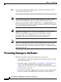
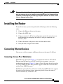
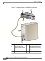
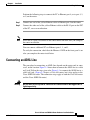
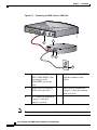
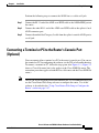
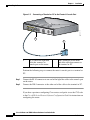
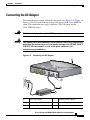
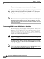
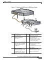
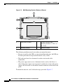
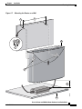
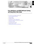
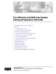
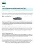
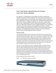
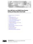
C H A P T E R
2
Installation
This chapter provides information on the following topics:
•
Preparing for Installation
•
Preventing Damage to the Router
•
Installing the Router
•
Using the Router LEDs to Check Links
•
Mounting the Router
Cisco 836 Router and SOHO 96 Router Hardware Installation Guide
78-15281-02
2-27
Chapter 2
Installation
Preparing for Installation
Preparing for Installation
This section provides information on safety, mounting of the router, and
unpacking of the router box.
Safety
This section provides safety warnings and electrostatic and router damage
information for the Cisco 836 and Cisco SOHO 96 routers.
Warnings
Before installing the router, read the following warnings:
Warning
Only trained and qualified personnel should be allowed to install or replace this
equipment.
Warning
Read the installation instructions before you connect the system to its power
source.
Warning
Before working on a system that has a standby/off switch, turn off the power
switch to standby and unplug the power cord.
Warning
Before working on equipment that is connected to power lines, remove jewelry
(including rings, necklaces, and watches). Metal objects will heat up when
connected to power and ground and can cause serious burns or weld the metal
object to the terminals.
Cisco 836 Router and SOHO 96 Router Hardware Installation Guide
2-28
78-15281-02
Chapter 2
Installation
Preparing for Installation
Warning
To avoid electric shock, do not connect safety extra-low voltage (SELV) circuits
to telephone-network voltage (TNV) circuits. LAN ports contain SELV circuits,
and WAN ports contain TNV circuits. Some LAN and WAN ports both use RJ-45
connectors. Use caution when connecting cables.
Warning
During this procedure, wear grounding wrist straps to avoid ESD damage. Do
not directly touch the backplane during with your hand or any metal tool, or you
could shock yourself.
Warning
This equipment is not designed for making emergency telephony calls when the
power fails. Alternative arrangements should be made for access to emergency
services. Access to emergency services can be affected by any call-barring
function of this equipment.
Warning
To reduce the risk of fire, use only No.26 AWG or large telecommunication line
cord.
Warning
This equipment contains a ring signal generator (ringer), which is a source of
hazardous voltage. Do not touch the RJ-11 (phone) port wires (conductors), the
conductors of a cable connected to the RJ-11 port, or the associated
circuit-board when the ringer is active. The ringer is activated by an incoming
call.
Warning
Ths ISDN connection is regarded as a source of voltage that should be
inaccessible to user contact. Do not attempt to tamper with or open any public
telephone operator (PTO)-provided equipment or connection hardware. Any
hardwired connection (other than by a nonremovable, connect-one-time-only
plug) must be made only by PTO staff or suitably trained engineers.
Cisco 836 Router and SOHO 96 Router Hardware Installation Guide
78-15281-02
2-29
Chapter 2
Installation
Preparing for Installation
Warning
Network hazardous voltages are present in the ISDN cable. If you detach the
ISDN cable, detach the end away from the router first to avoid possible electric
shock. Network hazardous voltages also are present on the system card in the
area of the ISDN port (RJ-45 connector), regardless of when power is turned off
(by pressing power switch to standby).
Warning
Ultimate disposal of this product should be handled according to all national
laws and regulations.
Preventing Electrostatic Discharge Damage
Electrostatic discharge (ESD) is a transfer of electrostatic charge between bodies
of different electrostatic potentials, such as an operator and a piece of electrical
equipment. It occurs when electronic components are improperly handled, and it
can damage equipment and impair electrical circuitry. Electrostatic discharge is
more likely to occur with the combination of synthetic fibers and dry atmosphere.
Always follow these steps to prevent ESD when you remove and replace
components:
Step 1
Wear an ESD-preventive wrist strap that you provide, ensuring that it makes good
skin contact.
Caution
To properly guard against ESD damage and shocks, the wrist strap and cord must
operate effectively.
Step 2
Do not touch any exposed contact pins or connector shells of interface ports that
do not have a cable attached.
If cables are connected at one end only, do not touch the exposed pins at the
unconnected end of the cable.
Cisco 836 Router and SOHO 96 Router Hardware Installation Guide
2-30
78-15281-02
Chapter 2
Installation
Preparing for Installation
Note
Caution
This device is intended for use in residential and commercial environments only.
Periodically check the resistance value of the antistatic strap, which should be
between 1 and 10 megohms (Mohm).
Unpacking the Box
Table 2-1 lists the items that come with your router. All these items are in the
accessory kit that is inside the box that your router came in. If any of the items is
missing or damaged, contact your customer service representative.
Table 2-1
Router Box Contents
•
Power cord (black)
•
Desktop power supply
•
ADSL cable (lavender)
•
Console cable, RJ-45-to-DB-9 (light blue)
•
ISDN cable (orange)
•
Ethernet cable (yellow)
•
Product documentation
To prepare for installation, follow these steps:
Step 1
Remove yellow Ethernet cable, light blue console cable, and product
documentation from the accessory kit. Remove the desktop power supply, orange
ISDN S/T cable, the lavender ADSL cable, and the black power cord from the
box. Gather the Ethernet devices to be connected to the router: hub, server,
workstation, or PC.
Step 2
If you plan to connect an analog telephone or fax machine, gather these devices.
You must also provide the telephone cable to connect each device.
Cisco 836 Router and SOHO 96 Router Hardware Installation Guide
78-15281-02
2-31
Chapter 2
Installation
Preventing Damage to the Router
Step 3
If you plan to configure the software using a terminal or PC connected to the
router, provide the terminal or PC.
Note
Unless otherwise specified, a lavender straight-through RJ-11to RJ-11 cable is
provided as the ADSL cable. The user can select one of two other cables
instead—a crossover RJ-11 to RJ-11 ADSL cable or a straight-through RJ-11 to
RJ- 45 ADSL cable. Each router is supplied with only one ADSL cable, which the
user selected during the ordering process.
Note
The optional orange ISDN S/T cable used for connecting a Cisco 836 router’s
ISDN port to the ISDN service provider is for dial backup and remote
management. The Cisco SOHO 96 router needs this cable for remote
management. The user may order this optional cable additionally.
Note
There are six different power cords. Each was designed to meet the specifications
of the cable wall jack for a particular country. Each of the six power cords is
different from the others. The default cord shown in Figure 2-1 is European Union
standard specification.
Preventing Damage to the Router
Follow these guidelines when connecting devices to your router:
•
Connect the color-coded cables supplied by Cisco Systems to the color-coded
ports on the back panel.
•
If you must supply your own cables, see Appendix A, “Specifications and
Cables,” for cable specifications. If this appendix does not provide
specifications for a particular cable, we strongly recommend that you order
the cable from Cisco Systems.
•
If the symbol of suitability ( ) appears above a port, you can connect the port
directly to a public network that follows the European Union standards.
Cisco 836 Router and SOHO 96 Router Hardware Installation Guide
2-32
78-15281-02
Chapter 2
Installation
Installing the Router
Warning
If the symbol of suitability with an overlaid cross ( ) appears above a port, you
must not connect the port to a public network that follows the European Union
standards. Connecting the port to this type of public network can cause severe
injury or damage to your router.
Installing the Router
To install the router, you need to perform the following tasks in the following
order:
1.
Connect the Ethernet devices to the router.
2.
Connect the ADSL line.
3.
Connect a terminal or PC to the configuration port of the router if you are
troubleshooting or configuring the router by using the command-line
interface (CLI).
4.
Connect the router to the power source and turn on the router.
5.
Verify the links, using the router LEDs.
Connecting Ethernet Devices
You can use a cable to connect an Ethernet devices to the router’s LAN port.
Connecting a Server, PC, or Workstation
Follow the steps given after Figure 2-1 to connect the router to a PC with an
Ethernet network interface card (NIC) installed, or to connect a server or
workstation to the router. (Figure 2-1 shows a Cisco 836 router, but it also applies
to a Cisco SOHO 96 router. The procedure applies to both the Cisco 836 router
and the Cisco SOHO 96 router.)
The Ethernet port on the Cisco 836 router and the Cisco SOHO 96 router supports
the auto-crossover function, whose autosensing ability allows the router to
connect automatically to the hub or PC.
Cisco 836 Router and SOHO 96 Router Hardware Installation Guide
78-15281-02
2-33
Chapter 2
Installation
Installing the Router
Figure 2-1
Connecting a Server, PC, or Workstation to the Router
1
2
ETHERN
ET
CONSOLE
4
3
Cisco 836
ISDN S/T
ADSL o ISD
N
2
1
3
82711
4
5
1
Cisco 836 router
4
PC
2
One end of the yellow
Ethernet cable that connects
to Ethernet port 4 on the
router
5
Other end of the Ethernet cable
that connects to the RJ-45 port
on the network interface card
(NIC)
3
Ethernet port 4
Cisco 836 Router and SOHO 96 Router Hardware Installation Guide
2-34
78-15281-02
Chapter 2
Installation
Installing the Router
Perform the following steps to connect the PC to Ethernet port 4 (or to port 1, 2,
or 3) on the router:
Step 1
Connect one end of the yellow Ethernet cable to Ethernet port 4 on the router.
Step 2
Connect the other end of the yellow Ethernet cable to the RJ-45 port on the NIC
of the PC, server or workstation.
Note
Leave the PCs that you connect to the router turned off until after you complete
the router installation.
You can connect additional PCs to Ethernet ports 1, 2, and 3.
To verify the connection, check that the Ethernet 1 LED on the front panel is on
after you complete the router installation.
Connecting an ADSL Line
The procedure for connecting an ADSL line depends on the router and, in some
cases, on the location. Figure 2-2 shows how to connect the ADSL line to a cable
wall jack. Follow the steps given after Figure 2-2 to connect the ADSL line to a
cable wall jack. (Figure 2-2 depicts a Cisco 836 router, but it also applies to the
Cisco SOHO 96 router. The connection steps apply to both the Cisco 836 router
and the Cisco SOHO 96 router.)
Warning
Do not work on the system or connect or disconnect cables during periods of
lightning activity.
Cisco 836 Router and SOHO 96 Router Hardware Installation Guide
78-15281-02
2-35
Chapter 2
Installation
Installing the Router
Figure 2-2
Connecting an ADSL Line to a Wall Jack
ETHERNE
T
CONSOLE
4
3
Cisco 836
ISDN S/T
ADSL o ISDN
2
1
+18 VDC
82716
ON
OFF
1
2
3
4
5
Note
1
One end of the ADSL over
ISDN (ADSLoISDN) cable
that connects to the
ADSLoISDN port on the
router
4
RJ-11 end of the ADSLoISDN
cable that connects to the
splitter
2
ADSL splitter provided by
ADSL service provider
5
Other end of the unshielded
Category 5 cable that connects
to the wall jack
3
RJ-11 end of an unshielded
Category 5 cable that
connects to splitter
The user has to provide the unshielded Category 5 cable to connect to the splitter.
Cisco 836 Router and SOHO 96 Router Hardware Installation Guide
2-36
78-15281-02
Chapter 2
Installation
Installing the Router
Perform the following steps to connect the ADSL line to a cable wall jack:
Step 1
Connect the RJ-11 end of the ADSL over ISDN cable to the ADSLoISDN port on
the router.
Step 2
Connect the other RJ-11 end of the ADSL over ISDN cable to the splitter’s local
ADSL connector port.
Step 3
Connect the unshielded Category 5 cable from the splitter’s outside ADSL port to
a wall jack.
Connecting a Terminal or PC to the Router’s Console Port
(Optional)
You can connect either a terminal or a PC to the router’s console port. You can use
the terminal or PC for configuring the software via the CLI or for troubleshooting.
To connect a terminal or PC, follow the steps given after Figure 2-3. (Figure 2-3
shows a Cisco 836 router, but it also applies to the Cisco SOHO 96 router. The
connection procedure applies to both the Cisco 836 router and the Cisco SOHO 96
router.)
Note
Unless you are an experienced network administrator, it is recommended that you
use the Cisco Router Web Setup software to configure the router. Use of this
software is described in the “Using Cisco Router Web Setup to Configure the
Router” section on page 2-47.
Cisco 836 Router and SOHO 96 Router Hardware Installation Guide
78-15281-02
2-37
Chapter 2
Installation
Installing the Router
Figure 2-3
Connecting a Terminal or PC to the Router’s Console Port
ETHERN
ET
CONSOL
E
4
3
Cisco 836
ISDN S/T
ADSL
2
1
+18 VDC
ON
82717
OFF
1
2
1
RJ-45 end of the light blue
cable that connects to
console port on the router
2
DB-9 connector on the other
end of the cable that connects to
the terminal or PC
Perform the following steps to connect the router’s console port to a terminal or
PC:
Step 1
Connect the RJ-45 connector at one end of the light blue cable to the console port
on the router.
Step 2
Connect the DB-9 connector at the other end of the cable to the terminal or PC.
If you have experience configuring Cisco routers and prefer to use the CLI, refer
to the Cisco 800 Series Routers Software Configuration Guide for instructions on
configuring the router.
Cisco 836 Router and SOHO 96 Router Hardware Installation Guide
2-38
78-15281-02
Chapter 2
Installation
Installing the Router
Connecting the AC Adapter
To connect the power supply, follow the steps given after Figure 2-4. (Figure 2-4
depicts a Cisco 836 router, but the process also applies to the Cisco SOHO 96
router. The connection steps apply to both the Cisco 836 router and the
Cisco SOHO 96 router.)
Warning
The device is designed to work with TN power systems.
Warning
This product relies on the building’s installation for short-circuit (overcurrent)
protection. Ensure that a fuse or circuit breaker no larger than 120 VAC, 15A U.S.
(240 VAC, 16A international) is used on the phase conductors (all
current-carrying conductors).
Figure 2-4
Connecting the AC Adapter
1
ETHERN
ET
CONSOL
E
4
3
Cisco 836
ISDN S/T
ADSL o ISDN
2
+18 VDC
1
ON
82712
OFF
2
3
5
4
1
Cisco 836 router
4
Desktop power supply
2
Router input jack
5
Power cord plug
3
Power cord
Cisco 836 Router and SOHO 96 Router Hardware Installation Guide
78-15281-02
2-39
Chapter 2
Installation
Installing the Router
Perform the following steps to connect the router to the AC adapter:
Step 1
Connect one end of the power supply cable to the router’s input jack.
Step 2
Connect the other end of the power supply cable to the desktop power adapter.
Step 3
Plug the power cord of the desktop power adapter into an electrical outlet.
Note
Be sure to use the power supply that was shipped with your router. Although you
may be able to connect another Cisco power supply to your router, that power
supply may not provide all the features that are provided by the power supply that
shipped with your router.
Connecting ISDN Port to ISDN Service Provider
The Cisco 836 router is designed with the dial backup function, allowing you to
connect the ISDN S/T port to the ISDN service provider as a backup link to the
WAN port in case the ADSL service goes down. The Cisco 836 router supports
both the dial backup and remote management features; the Cisco SOHO 96 router
supports only the remote management function.
Note
To make a connection to the ISDN service, you need to connect the orange ISDN
S/T cable to the ISDN port.
To connect the router’s ISDN S/T port to the ISDN service provider, follow the
steps given after Figure 2-6. This procedure applies to both the Cisco 836 router
and the Cisco SOHO 96 router.
Note
The user must provide the two unshielded Category 5 cables that connect the NT1
box to the splitter and that connect the splitter to the wall jack.
Cisco 836 Router and SOHO 96 Router Hardware Installation Guide
2-40
78-15281-02
Chapter 2
Installation
Installing the Router
Figure 2-5
Connecting the ISDN Port to the ISDN Service Provider
ETHERNET
CONSOLE
4
3
Cisco 836
ISDN S/T
ADSL o ISDN
2
1
+18 VDC
82881
ON
OFF
2
1
5
3
4
6
7
8
1
ISDN S/T port on the
Cisco 836 router
5
ADSL splitter provided by
ADSL service provider
2
Network termination 1
(NT1) box
6
Other end of the first
unshielded Category 5 cable
that connects to the telephone
line port on the splitter
3
RJ-45 end of the ISDN S/T 7
cable that connects the ISDN
S/T port to the S/T port on
the NT1 box
One end of the second
unshielded Category 5 cable
that connects the
telecommunication service port
on the splitter.
4
8
One end of the first
unshielded Category 5 cable
that connects the U port on
the NT1 box to the splitter
Other end of the second
unshielded Category 5 cable
connects to the wall jack
Cisco 836 Router and SOHO 96 Router Hardware Installation Guide
78-15281-02
2-41
Chapter 2
Installation
Using the Router LEDs to Check Links
Perform the following steps to connect the Cisco 836 router’s ISDN port to the
ISDN service provider:
Step 1
Connect one end of the orange ISDN S/T cable to the Cisco 836 router’s ISDN
S/T port.
Step 2
Connect the other end of the orange ISDN S/T cable to the S/T port on the NT1
box.
Step 3
Connect the first unshielded Category 5 cable from the U port on the NT1 box to
the telephone line port on the splitter.
Step 4
Connect the second unshielded Category 5 cable from the telecommunication
service port on the splitter to the wall jack to allow a link to the network service
provider.
Note
There are RJ-45 connectors at both ends of the default orange ISDN S/T cable
used in the preceding procedure. However, an RJ-45 to RJ-11 ISDN S/T cable is
available upon request if the wall jack at the site requires an RJ-11 connector.
Contact your router reseller for the appropriate cable.
Note
The cable for connecting the NT1 box to the splitter is not included in the
accessory kit. The user must provide this cable.
Using the Router LEDs to Check Links
Use the LEDs on the front of the router to check the links between the router and
any attached Ethernet devices or telephone. See Table 1-2 on page 1-5 to verify
the link status of devices attached to the Cisco 836 and Cisco SOHO 96 routers.
Cisco 836 Router and SOHO 96 Router Hardware Installation Guide
2-42
78-15281-02
Chapter 2
Installation
Mounting the Router
Mounting the Router
You can mount the router on one of the following surfaces:
•
Table or other horizontal surface
•
Wall or other vertical surface
Mounting on a Table
Place the router firmly on a table, and perform the tasks identified in the
“Installing the Router” section on page 2-33.
Caution
Do not cover or obstruct the router vents, which are located on the sides of the
router. If the vents are covered or obstructed, overheating could occur and cause
damage to the router.
Mounting on a Wall
You can mount the router on a wall or other vertical surface by using the molded
mounting brackets on the bottom of the router and two number-six, 3/4-in.
(M3.5 x 20 mm) screws. You must provide the screws. Figure 2-7 shows the
mounting brackets.
Caution
If you are mounting the router on drywall, use two hollow-wall anchors (1/8 in.
with 5/16-in. drill bit, or M3 with 8-mm drill bit) to secure the screws. If the
screws are not properly anchored, the strain of the network cable connections
could pull the router from the wall.
Cisco 836 Router and SOHO 96 Router Hardware Installation Guide
78-15281-02
2-43
Chapter 2
Installation
Mounting the Router
Figure 2-6
Wall-Mounting Brackets (Bottom of Router)
1
2
3
80289
4
1
Front panel of router
3
Distance between two
mounting brackets (7 5/8 in. or
19.35 cm)
2
Mounting bracket
4
Bottom of router
The following conditions must be met when you mount the router:
•
Because you will use the LEDs as status and problem indicators, the LEDs on
the front panel must face upward and must be easily visible.
•
The back panel must face downward to reduce strain on the cable
connections.
•
The power supply must rest on a horizontal surface such as the floor or a
table. If the power supply is not supported, it could place strain on the power
supply cable and cause it to disconnect from the connector on the router back
panel.
To mount the router on a wall, follow the steps given after Figure 2-7.
Cisco 836 Router and SOHO 96 Router Hardware Installation Guide
2-44
78-15281-02
Chapter 2
Installation
Mounting the Router
Figure 2-7
Mounting the Router on a Wall
2
1
3
OK
7
CD
AD R
SL XD
IS TX
DN D
1
CH
CI
SC
O
1
CH
2
80
0
1
ET
RI
ES
2
3
HE 4
RN
ET
SE
RXD TXD
4
82720
5
6
Cisco 836 Router and SOHO 96 Router Hardware Installation Guide
78-15281-02
2-45
Chapter 2
Installation
Mounting the Router
1
Two number-six, 3/4-in. screws
5
Maximum distance between the
router and the power supply (6 ft
[1.8 m])
2
Distance between the two screws
(7 5/8 in. [19.35 cm])
6
Horizontal surface for placing the
power supply
3
Cisco 836 router
7
Distance between the screw and
the wall (1/8 in. [0.32 cm])
4
Mounting brackets
Perform the following steps to mount the router on the wall:
Step 1
Secure two screws 7 5/8 inches (19.35 centimeters) apart into a wall and 1/8 inch
(0.32 centimeter) from the wall.
Step 2
Hang the router on the screws as shown in Figure 2-8.
Step 3
Place the power supply on a horizontal surface.
Configuring the Router
When you finish installing the router, you must configure the router software.
First, check the PC configurations to ensure that all the connected PCs will be able
to communicate with the router. Then configure the router software, using the web
interface.
Checking the PC Configuration
Each PC that is connected to the router must be configured to use TCP/IP and to
obtain its IP address automatically. Follow these steps to configure each PC that
is running Microsoft Windows NT or Microsoft Windows 95, 98, 2000, Windows
ME, and Windows XP. If the PC is running a different version of Microsoft
Windows, refer to the documentation that came with the PC.
Cisco 836 Router and SOHO 96 Router Hardware Installation Guide
2-46
78-15281-02
Chapter 2
Installation
Mounting the Router
Step 1
Start the PC, and open the Control Panel.
Step 2
Click the Network icon to display the Network window.
Step 3
Verify that TCP/IP has been added and associated with the Ethernet adapter.
TCP/IP is shown as a cable icon in the Configuration window on Microsoft
Windows 95 and 98; it is shown as a cable icon in the Protocol window on
Microsoft Windows NT. If the icon is not visible, click Add, and add the
Microsoft TCP/IP protocol.
Step 4
To verify that the PC is configured to obtain an IP address automatically, click the
TCP/IP cable icon, and select the IP address tab in the TCP/IP Properties
window. Check Obtain an IP address from a DHCP server if it is not checked.
The IP address and Subnet mask fields should be grayed out.
Step 5
Click OK to accept all changes and exit this window. Then click OK in the
Network window.
Step 6
If you are prompted, click Yes to reboot the PC.
For more information on how to configure TCP/IP, refer to the Cisco Router Web
Setup Troubleshooting Guide, which is available on Cisco.com.
Using Cisco Router Web Setup to Configure the Router
Cisco strongly recommends that inexperienced network administrators use the
Cisco Router Web Setup application that has been installed on the router. To use
this application, complete the following steps:
Step 1
Start, or restart, one of the PCs connected to the router through Ethernet port 1,
2, 3, or 4.
Step 2
Open a web browser. Make sure that your browser is set to work in online mode.
Step 3
•
In Internet Explorer, click the File menu, and verify that the “work offline”
option is unchecked.
•
In Netscape, the default selection in the File menu is set to work online.
Enter the universal resource locator (URL) http://10.10.10.1. The CRWS home
page will appear in one or two minutes.
Cisco 836 Router and SOHO 96 Router Hardware Installation Guide
78-15281-02
2-47
Chapter 2
Installation
Mounting the Router
Tip
If the CRWS home page does not appear when you enter the URL
http://10.10.10.1, test the connection between the PC and the router by doing the
following:
1.
Check that the OK LED on the router is on, and check the cable connection
between the router and the PC.
2.
If the CRWS home page still does not appear, verify that the web browser’s
“work offline” option is disabled.
3.
If the web page still does not appear, verify that your PC is automatically
configured to receive an IP address. Follow the instructions in the
Cisco Router Web Setup Troubleshooting Guide section, which is available on
Cisco.com.
4.
If the PC is configured to automatically receive an IP address, but the web
page still does not appear, select Start/Run, type winipcfg in the Run
window, and examine the address in the IP address field. The address should
be in the format 10.10.10.X, in which X is a number that is equal to or greater
than 2; for example, 10.10.10.2, or 10.10.10.3. If the IP address is not in this
format, verify that an Ethernet adapter name is visible in the Adapter field. If
there is no name in the field, return to Step 3 in the “Checking the PC
Configuration” section on page 2-46 and add TCP to the list of protocols.
Then return to the “Using Cisco Router Web Setup to Configure the Router”
section on page 2-47, and complete the procedure.
Step 4
If you have no special configuration requirements, click the Router Setup link
on the home page, and then click Easy Setup. (This may appear as Quick Setup
on some models.) Then, enter the username and password provided to you by
your Internet service provider, and click Apply.
Step 5
If you need to configure special features such as Network Address Translation
(NAT), click the appropriate links on the home page, and complete the
configuration screens.
Step 6
Click the Password link on the home page, and set a password for the router.
Step 7
Click the Test Connection link on the home page, and allow the connection to be
tested.
Cisco 836 Router and SOHO 96 Router Hardware Installation Guide
2-48
78-15281-02
Chapter 2
Installation
Mounting the Router
Step 8
Select Start/Run, and type winipcfg in the Open field of the Run window. When
the IP Config window appears, click Release to release the PC’s IP address.
Then click Renew to renew the PC’s IP address.
Alternatively, open the Run window, and enter ipconfig /release to release the
PC’s IP address.Then enter ipconfig /renew to renew the IP address of the PC.
Step 9
Open a web browser on the PC, and connect to a website.
The router installation is complete when you have connected to a website.
Cisco 836 Router and SOHO 96 Router Hardware Installation Guide
78-15281-02
2-49
Chapter 2
Installation
Mounting the Router
Cisco 836 Router and SOHO 96 Router Hardware Installation Guide
2-50
78-15281-02