1
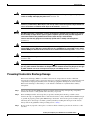
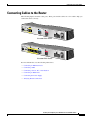
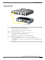
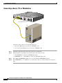
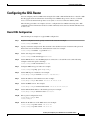
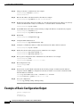
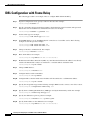
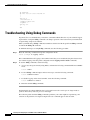
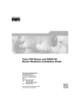
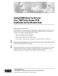
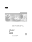
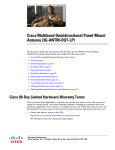
Installing and Configuring Cisco 802 IDSL and
Cisco 804 IDSL Routers
Overview
Cisco 802 IDSL and Cisco 804 IDSL routers offer high-speed digital connections using an ISDN line
and support line rates up to 144 kilobits per second (kbps). Integrated Services Digital Network (ISDN)
Digital Subscriber Line (IDSL) expands DSL connectivity for customers who are outside the Service
Provider’s range for DSL or for those who are unable to qualify for DSL connections.
This document describes the setup and configuration of your routers and contains the following sections:
•
Before You Start
•
Unpacking the Router
•
Connecting Cables to the Router
•
Configuring the IDSL Router
Corporate Headquarters:
Cisco Systems, Inc., 170 West Tasman Drive, San Jose, CA 95134-1706 USA
Copyright © 2005 Cisco Systems, Inc. All rights reserved.
Before You Start
The following figure shows a typical setup of the Cisco 804 IDSL router.
Cisco 804 IDSL Router
Internet
Personal
computer
Power
supply
Corporate
LAN
Personal
computer
Personal
computer
Personal
computer
Before You Start
Before you begin installing your Cisco IDSL router, read the following topics:
•
Safety
•
Preventing Electrostatic Discharge Damage
•
Preventing Router Damage
Safety
Before installing the router, read the following warnings:
.
Warning
Only trained and qualified personnel should be allowed to install, replace, or service this equipment.
Statement 1030
Warning
Read the installation instructions before connecting the system to the power source. Statement 1004
Installing and Configuring Cisco 802 IDSL and Cisco 804 IDSL Routers
2
78-10368-03
Before You Start
Warning
Before working on a system that has a standby/off switch, turn off the power by pressing the power
switch to standby and unplug the power cord. Statement 150
Warning
Before working on equipment that is connected to power lines, remove jewelry (including rings,
necklaces, and watches). Metal objects will heat up when connected to power and ground and can
cause serious burns or weld the metal object to the terminals. Statement 43
Warning
The IDSL connection is regarded as a source of voltage that should be inaccessible to user contact.
Do not attempt to tamper with or open any public telephone operator (PTO)-provided equipment or
connection hardware. Any hardwired connection (other than by a nonremovable,
connect-one-time-only plug) must be made only by PTO staff or suitably trained engineers.
Statement 23
Warning
To avoid electric shock, do not connect safety extra-low voltage (SELV) circuits to telephone-network
voltage (TNV) circuits. LAN ports contain SELV circuits, and WAN ports contain TNV circuits. Some
LAN and WAN ports both use RJ-45 connectors. Use caution when connecting cables. Statement 1021
Warning
Ultimate disposal of this product should be handled according to all national laws and regulations.
Statement 1040
Warning
If the symbol of suitability with an overlaid cross ( ) appears above a port, you must not connect the
port to a public network that follows the European Union standards. Connecting the port to this type
of public network can cause severe personal injury or can damage the unit. Statement 1031
Preventing Electrostatic Discharge Damage
Electrostatic discharge (ESD) is a transfer of electrostatic charge between bodies of different
electrostatic potentials, such as an operator and a piece of electrical equipment. It occurs when electronic
components are improperly handled, and it can damage equipment and impair electrical circuitry.
Electrostatic discharge is more likely to occur with the combination of synthetic fibers and dry
atmosphere.
Step 1
Always use the following ESD-prevention procedures when removing and replacing components:
Connect the chassis to earth ground with a wire that you provide.
Step 2
Wear an ESD-preventive wrist strap that you provide, ensuring that it makes good skin contact.
Connect the clip to an unpainted surface of the chassis frame to safely channel unwanted ESD voltages
to ground. To properly guard against ESD damage and shocks, the wrist strap and cord must operate
effectively. If no wrist strap is available, ground yourself by touching the metal part of the chassis.
Always follow the guidelines in the preceding section, “Safety.”
Step 3
Do not touch any exposed contact pins or connector shells of interface ports that do not have a cable
attached.
Installing and Configuring Cisco 802 IDSL and Cisco 804 IDSL Routers
78-10368-03
3
Unpacking the Router
If cables are connected at one end only, do not touch the exposed pins at the unconnected end of the
cable.
Note
Caution
This device is intended for use in residential and commercial environments only.
Periodically check the resistance value of the antistatic strap, which should be between 1 and 10
megohms (Mohms).
Preventing Router Damage
Use the following guidelines when connecting devices to your router:
Warning
•
Connect the color-coded cables supplied by Cisco to the color-coded ports on the back panel.
•
If the symbol of suitability ( ) appears above a port, you can connect the port directly to a public
network that follows the European Union standards.
If the symbol of suitability with an overlaid cross appears above a port, you must not connect the
port to a public network that follows the European Union standards. Connecting the port to this type
of public network can cause severe personal injury or can damage the unit. Statement 1031
Unpacking the Router
Your router package should include the following items:
•
Ethernet cable (yellow)
•
IDSL cable (red)
•
RJ-45 to RJ-11 adapter cable (for use with red IDSL cable)
•
Desktop power supply
•
Power cord (black)
•
Console cable (light blue)
•
DB-9 to RJ-45 adapter (for use with light blue console cable)
•
Product documentation
Installing and Configuring Cisco 802 IDSL and Cisco 804 IDSL Routers
4
78-10368-03
Connecting Cables to the Router
Connecting Cables to the Router
The following figures show the router ports. These ports and the cables are color-coded to help you
connect the cables correctly.
TO HUB
TO PC
ETHERN
ET
Cisco 80
LINK
CONSOL
2 IDSL
E
IDSL
10BASE
T
+5, -24,
-71 VDC
Cisco 802 IDSL Router
TO HUB
TO PC
ETHERN
ET 10 BA
Cisco 80
4 IDSL
SE T
CONSOL
E
IDSL
1
2
3
+5, -24,
-71 VDC
4
Cisco 804 IDSL Router
For more information, see the following subsections:
•
Connecting an Ethernet Device
•
Connecting a Hub
•
Connecting a Server, PC, or Workstation
•
Connecting an IDSL Line
•
Connecting the Power Supply
•
Verifying Router Connections
Installing and Configuring Cisco 802 IDSL and Cisco 804 IDSL Routers
78-10368-03
5
Connecting Cables to the Router
Connecting an Ethernet Device
This section describes how to connect a hub, server, PC, or workstation with a 10- or 10/100-Mbps
network interface card (NIC).
Before connecting an Ethernet device, you need to know the following:
Caution
•
Cisco provides one yellow cable to connect an Ethernet device. If you want to connect more than
one device, you must provide additional straight-through cables. See the Cisco 800 Series Routers
Hardware Installation Guide for straight-through cable specifications.
•
The TO HUB/TO PC button corresponds to the Ethernet port on Cisco 802 IDSL routers and to
Ethernet port 1 on Cisco 804 IDSL routers.
Always connect the yellow cable or Ethernet cable to the yellow ports on the router. Do not connect the
cable to an IDSL port or to a Network Termination 1 (NT1) device. Accidently connecting the cable to
the wrong port can damage your router.
Installing and Configuring Cisco 802 IDSL and Cisco 804 IDSL Routers
6
78-10368-03
Connecting Cables to the Router
Connecting a Hub
TO HUB
TO PC
Cisco 804
ETHERN
ET 10 BAS
ET
IDSL
CONSO
LE
IDSL
1
2
3
+5, -24,
-71 VDC
4
Cisco 804 IDSL Router
1X
2X
SPEED
LED
100Bas
eTX SO
LID
10Base
T BLI
NK
10/100
3X
4X
1 2 3
4
5 6 7
8
5X
6X
7X
8X
MDI
MDI-X
Cisco Micro Hub 10/100
Step 1
Connect the yellow cable to one of the following ports:
•
The yellow Ethernet port on your Cisco 802 IDSL router.
•
Any of the yellow Ethernet ports on your Cisco 804 IDSL router.
Step 2
Connect the other end of the cable to the hub.
Step 3
Check the LED corresponding to the connected port after router power-up:
Step 4
•
The LINK LED is on the Cisco 802 IDSL back panel.
•
ETHERNET 1, 2, 3, and 4 LEDs are on the Cisco 804 IDSL front panel.
If the LED corresponding to the connected port is not on, do the following:
•
If the LINK or ETHERNET 1 LED is not on, try pressing the TO HUB/TO PC button.
•
If the ETHERNET 2, 3, or 4 LED is not on, press the equivalent of the router TO HUB/TO PC button
on your hub.
Installing and Configuring Cisco 802 IDSL and Cisco 804 IDSL Routers
78-10368-03
7
Connecting Cables to the Router
Connecting a Server, PC, or Workstation
TO HUB
TO PC
Cisco 804
ETHERN
ET 10 BAS
ET
IDSL
CONSO
LE
+5, -24,
IDSL
1
2
3
-71 VDC
4
Cisco 804 IDSL Router
OK
SER 0
AUX
LAN
AUX
PC
Connect the yellow cable to one of the following ports:
•
The yellow Ethernet port on your Cisco 802 IDSL router.
•
Any of the yellow Ethernet ports on your Cisco 804 IDSL router.
Step 1
Connect the other end of the cable to the server, PC, or workstation.
Step 2
Check the LED corresponding to the connected port after router power-up:
•
The LINK LED is on the Cisco 802 IDSL back panel.
•
ETHERNET 1, 2, 3, and 4 LEDs are on the Cisco 804 IDSL front panel.
Step 3
If the LINK or ETHERNET 1 LED is not on, try pressing the TO HUB/TO PC button.
Step 4
If the ETHERNET 2, 3, or 4 LED is not on, see the Cisco 800 Series Routers Hardware Installation
Guide.
Installing and Configuring Cisco 802 IDSL and Cisco 804 IDSL Routers
8
78-10368-03
Connecting Cables to the Router
Connecting an IDSL Line
Caution
Always connect the yellow cable or Ethernet cable to the yellow ports on the router. Do not connect the
cable to an IDSL port or to a Network Termination 1 (NT1) device. Accidently connecting the cable to
the wrong port can damage your router.
TO HUB
TO PC
ETHERN
ET 10 BAS
Cisco 80
4 IDSL
ET
CONSO
LE
IDSL
1
2
3
+5, -24,
-71 VDC
4
Cisco 804 IDSL Router
IDSL wall jack
RJ-45-to-RJ-11
adapter cable
Step 1
Connect the red cable to the red IDSL port.
Step 2
Connect the other end of the cable to the IDSL wall jack. If your wall jack has an RJ-11 connector, attach
the RJ-45-to-RJ-11 adapter cable to the red cable, and then connect the RJ-11 connector to the IDSL wall
jack.
Installing and Configuring Cisco 802 IDSL and Cisco 804 IDSL Routers
78-10368-03
9
Connecting Cables to the Router
Connecting the Power Supply
TO HUB
TO PC
Cisco 80
ETHERN
ET 10 BAS
ET
CONSO
4 IDSL
LE
IDSL
1
+5, -24,
-71 VDC
2
3
4
Cisco 804 IDSL Router
2
To electrical outlet
Desktop power supply
Step 1
Make sure the router power is off. Press the power switch to standby (
Step 2
Connect the power supply cable to the 8-pin connector on the router.
Step 3
Connect the power cord to the desktop power supply.
Step 4
Connect the other end of the power cord to an electrical outlet.
Step 5
Turn on the router. Press the power switch to on (|).
).
Verifying Router Connections
Verify the power connection and all other connections (links) by checking the LEDs in the table below.
If the LEDs are not on, see the troubleshooting information in the Cisco 800 Series Routers Hardware
Installation Guide.
Power/Link
LEDs To Check
Normal Patterns
Power
OK
On
To hub, server, PC, or
workstation
Cisco 802 IDSL back panel: LINK LED
On
To IDSL network using
IDSL port
NT1, LINE, CH1, or CH2
Cisco 804 IDSL front panel: ETHERNET
1, 2, 3, and 4 LEDs
On (CH1 or CH2 is on only when
the router has an active data
connection. With a 64 kbps
connection, only CH1 is on. With a
128 or 144 kbps connection, both
CH1 and CH2 are on).
Installing and Configuring Cisco 802 IDSL and Cisco 804 IDSL Routers
10
78-10368-03
Configuring the IDSL Router
Configuring the IDSL Router
You can configure your Cisco IDSL router using the Cisco IOS command-line interface or the Cisco 800
Fast Step application. For information about using Cisco 800 Fast Step, refer to the Cisco 800 DSL
Connection Kit document in the product accessory kit or on Cisco Connection Online (CCO).
The following procedures are examples of how to configure the Cisco IDSL router using Cisco IOS
commands. For more information about Cisco IOS commands, refer to the Cisco IOS documentation set
on Cisco.com.
Basic IDSL Configuration
The following is an example of a typical IDSL configuration.
Step 1
In global configuration mode, specify a name for the router. For example:
router(config)# hostname 802
Step 2
Specify a username and password. The username is the destination router’s hostname. The password
must be the same for both the host and destination routers. For example:
router(config)# username isp password cisco
Step 3
Set the switch type. For example:
router(config)# isdn switch-type basic-5ess
Step 4
Set the BRI interface to use the ISDN physical connection as a leased-line service. The following
example sets the line speed at 128 kbps:
router(config)# isdn leased-line bri0 128
Step 5
Configure DHCP relay pool name. For example:
router(config)# ip dhcp pool DHCPpoolLAN_0
Step 6
Set the DHCP pool of addresses. For example:
router(dhcp-config)# network 192.168.1.0 255.255.255.0
Step 7
Set the IP addresses of the DNS servers. For example:
router(dhcp-config)# dns-server 172.29.20.41 172.29.20.51
Step 8
Set the NetBIOS servers. For example:
router(dhcp-config)# netbios-name-server 172.29.20.41 172.29.20.51
Step 9
Set the Ethernet 0 IP address as the default gateway. For example:
router(dhcp-config)# default-router 192.168.1.1
Step 10
Exit to global configuration mode.
router(dhcp-config)# exit
router(config)#
Step 11
Define the IP addresses of the DNS servers. For example:
router(config)# ip name-server 172.29.20.41
router(config)# ip name-server 172.29.20.51
Installing and Configuring Cisco 802 IDSL and Cisco 804 IDSL Routers
78-10368-03
11
Example of Basic Configuration Output
Step 12
Change to interface command mode. For example:
router(config)# interface ethernet0
router(config-if)#
Step 13
Enter the IP address and subnet mask for the LAN. For example:
router(config-if)# ip address 192.168.1.1 255.255.255.0
Step 14
Enable Network Address Translation (NAT) on your LAN. The inside network address is not directly
routed to the Internet but is subject to translation to a routable address outside the LAN.
router(config-if)# ip nat inside
Step 15
Set the BRI interface IP address. In the following example, IP addresses are dynamically assigned:
router(config-if)# interface bri0
router(config-if)# ip address negotiated
Step 16
Enable PPP.
router(config-if)# encapsulation ppp
Step 17
Configure CHAP authentication.
router(config-if)# ppp authentication chap
Step 18
Configure a valid Internet address to which the inside network address will be translated.
router(config-if)# ip nat outside
Step 19
Define the router hostname and password to authenticate. For example:
router(config-if)# ppp chap hostname 802
router(config-if)# ppp chap password cisco
Step 20
Exit to global configuration mode. Add default route and interface. For example:
router(config-if)# exit
router(config)# ip route 0.0.0.0 0.0.0.0 bri0
Step 21
End configuration mode.
router(config)# end
router#
Step 22
In user mode, set global NAT commands. In the following example, all inside network addresses
assigned to interface BRI0 are configured for translation, and the access list that contains the inside
network addresses is defined.
router# ip nat inside source list 1 interface bri0 overload
router# access-list 1 permit 192.168.1.0 0.0.0.255
Step 23
Save your configuration.
router# copy running-config startup-config
Example of Basic Configuration Output
Current configuration:
!
version 12.0
no service pad
Installing and Configuring Cisco 802 IDSL and Cisco 804 IDSL Routers
12
78-10368-03
Example of Basic Configuration Output
service timestamps debug uptime
service timestamps log uptime
no service password-encryption
!
hostname cisco802
!
!
!
!
ip subnet-zero
!
isdn switch-type basic-5ess
isdn leased-line BRI0 128
ip dhcp pool DHCPoolLAN_0
network 192.168.1.0 255.255.255.0
dns-server 172.29.20.41 172.29.20.51
netbios-name-server 172.29.20.41 172.29.20.51
default-router 192.168.1.1
ip name-server 172.29.20.41
ip name-server 172.29.20.51
!
!
interface Ethernet0
ip address 192.168.1.1 255.255.255.0
no ip directed-broadcast
ip nat inside
!
interface BRI0
ip unnumbered negotiated
no ip directed-broadcast
encapsulation ppp
ppp authentication chap
ip nat outside
ppp chap hostname 802
ppp chap password cisco
!
ip classless
ip route 0.0.0.0 0.0.0.0 bri 0
!
ip nat inside source list 1 interface bri0 overload
access-list 1 permit 192.168.1.0 0.0.0.255
!
line con 0
transport input none
stopbits 1
line vty 0 4
end
cisco802#
Installing and Configuring Cisco 802 IDSL and Cisco 804 IDSL Routers
78-10368-03
13
IDSL Configuration with Frame Relay
IDSL Configuration with Frame Relay
The following procedure is an example of how to configure IDSL with Frame Relay.
Step 1
In global configuration mode, specify a name for the router. For example:
router(config)# hostname 802
Step 2
Specify a username and password. The username is the destination router’s hostname. The password
must be the same for both the host and destination routers. For example:
router(config)# username isp password cisco
Step 3
Set the switch type. For example:
router(config)# isdn switch-type basic-5ess
Step 4
Set the BRI interfaces to use the ISDN physical connection as a leased-line service. The following
example sets the line speed at 144 kbps:
router(config)# isdn leased-line bri0 144
router(config)# isdn leased-line bri0.1 144
Step 5
Change to interface command mode. For example:
router(config)# interface ethernet0
Step 6
Enter an IP address. For example:
router(config-if)# ip address 192.168.2.1 255.255.255.0
Step 7
Enable Network Address Translation (NAT) on your LAN. The inside network address is not directly
routed to the Internet but is subject to translation to a routable address outside the LAN.
router(config-if)# ip nat inside
Step 8
Change to BRI interface.
router(config-if)# interface bri0
Step 9
Configure interface with no IP address.
router(config-if)# no ip address
Step 10
Configure NAT so that the inside network address will be translated to a valid Internet address.
router(config-if)# ip nat outside
Step 11
Specify the encapsulation type. In the following example, IETF is used to connect to non-Cisco routers.
router(config-if)# encapsulation frame-relay ietf
Step 12
Specify the Local Management Interface (LMI) type used by the Frame Relay switch. For example:
router(config-if)# frame-relay lmi-type ansi
Step 13
Specify the subinterface point-to-point. For example:
router(config-if)# interface bri0:1 point-to-point
Step 14
Specify the IP address on the subinterface. For example:
router(config-if)# ip address 209.188.2.2 255.255.255.0
Installing and Configuring Cisco 802 IDSL and Cisco 804 IDSL Routers
14
78-10368-03
Example of Frame Relay Configuration Output
Step 15
Specify a DLCI number that is used to connect to the Internet service provider. For example:
router(config)# frame-relay interface dlci 16 ieft
Step 16
End configuration mode.
router(config)# end
router#
Step 17
In user mode, set global NAT commands. In the following example, all inside network addresses
assigned to interface BRI0 are configured for translation, and the access list that contains the inside
network addresses is defined.
router# ip nat inside source list 1 interface bri0 overload
router# access-list 1 permit 192.168.1.0 0.0.0.255
Step 18
Save your configuration.
router# copy running-config startup-config
Example of Frame Relay Configuration Output
Current configuration:
!
!
version 12.0
service timestamps debug uptime
service timestamps log uptime
!
hostname c802idsl
username isp password 0 cisco
!
!
ip subnet-zero
!
isdn switch-type basic-5ess
isdn leased-line BRI0 144
isdn leased-line BRI0.1 144
!
!
interface Ethernet0
ip address 192.168.2.1 255.255.255.0
ip nat inside
!
interface BRI0
no ip address
encapsulation frame-relay IETF
frame-relay lmi-type ansi
!
interface BRI0.1 point-to-point
ip address 209.188.2.2 255.255.255.0
frame-relay interface-dlci 16 IETF
ip nat outside
!
ip nat inside source list 1 interface bri0:1 overload
access-list 1 permit 192.168.2.0 0.0.0.255
Installing and Configuring Cisco 802 IDSL and Cisco 804 IDSL Routers
78-10368-03
15
Troubleshooting Using Debug Commands
ip classless
ip route 0.0.0.0 0.0.0.0 209.188.2.1
!
!
line con 0
exec-timeout 0 0
transport input none
stopbits 1
line vty 0 4
!
end
Troubleshooting Using Debug Commands
In general, Cisco recommends that you use these commands with the direction of your technical support
representative. Using the debug commands can disrupt operation of the router when your internetwork
is experiencing a high-load condition.
When you finish using a debug command, remember to disable it with the specific no debug command
or with the no debug all command.
To minimize the impact of using debug commands, use the following procedure:
Step 1
Enter the following command from global configuration mode:
router (config)# no logging console
This command disables all logging to the terminal or PC that you are troubleshooting the software from.
(To reenable logging, enter the global configuration mode logging console enable command.)
Step 2
To use the debug commands, do the following:
a.
Access any router port remotely using Telnet, and enter the following command while in user EXEC
mode:
router> enable
b.
To show debug command output and error messages, enter the following command:
router> terminal monitor
c.
To disable logging on the virtual terminal, enter the following command:
router> terminal no monitor
d.
Enter the desired debug commands.
Performing this procedure minimizes the load created because the console port no longer needs to
generate character-by-character processor interrupts.
The following table describes debug commands, problems your router might be experiencing, and
solutions to the problems. An output example from each command appears after the table.
Installing and Configuring Cisco 802 IDSL and Cisco 804 IDSL Routers
16
78-10368-03
Troubleshooting Using Debug Commands
Command
Possible Problem
Solution
show isdn status
(user EXEC mode).
• Improperly connected cable.
• Refer to troubleshooting information in Cisco 800
Series Routers Hardware Installation Guide.
• Damaged IDSL cable.
• Order a new red IDSL cable from your Cisco
reseller.
• Problem with IDSL line.
• Contact your telephone service provider to report
a problem.
See output 1 example
following this table.
If the problem continues after these steps, call your
Cisco reseller.
• Software configuration error for
router connected to Cisco 802
IDSL or Cisco 804 IDSL router.
• Check your router configuration. See the
documentation that shipped with your router for
more information.
debug ppp negotiation, • PAP or CHAP authentication
debug ppp
failed.
authentication
(privileged EXEC mode)
• For PAP, check the settings of the PAP hostname
and password for correct spelling and use of
uppercase and lowercase letters. If settings are
incorrect, reconfigure them.
See output 2 example
following this table.
• For CHAP, clear the existing hostname and
password. Reconfigure the hostname and
password.
Output 1 Example (show isdn status)
The current ISDN Switchtype = basic-ni1
ISDN BRI0 interface
Layer 1 Status:
DEACTIVATED
Layer 2 Status:
Layer 2 NOT Activated
Layer 3 Status:
No Active Layer 3 Call(s)
Activated dsl 0 CCBs = 0
Total Allocated ISDN CCBs = 0
isdn#
ISDN BR0:TX -> RRp sapi = 0 tei = 80 nr = 1
ISDN BR0:RX <- RRf sapi = 0 tei = 80 nr = 1
isdn#
ISDN BR0:TX -> RRp sapi = 0 tei = 81 nr = 1
ISDN BR0:RX <- RRf sapi = 0 tei = 81 nr = 1
ISDN BR0:TX -> RRp sapi = 0 tei = 80 nr = 1
ISDN BR0:RX <- RRf sapi = 0 tei = 80 nr = 1
isdn#und all
isdn#show isdn st
The current ISDN Switchtype = basic-dms100
ISDN BRI0 interface
Layer 1 Status:
ACTIVE
Layer 2 Status:
TEI = 80, State = MULTIPLE_FRAME_ESTABLISHED
TEI = 81, State = MULTIPLE_FRAME_ESTABLISHED
Layer 3 Status:
Installing and Configuring Cisco 802 IDSL and Cisco 804 IDSL Routers
78-10368-03
17
Obtaining Documentation
No Active Layer 3 Call(s)
Activated dsl 0 CCBs = 0
Output 2 Example (debug ppp negotiation and debug ppp authentication)
pico#ping 192.9.198.1
Type escape sequence to abort.
Sending 5, 100-byte ICMP Echos to 192.9.198.1, timeout is 2 seconds:
%LINK-3-UPDOWN: Interface BRI0: B-Channel 1, changed state to up
%LINK-5-CHANGED: Interface BRI0: B-Channel 1, changed state to up
ppp: sending CONFREQ, type = 3 (CI_AUTHTYPE), value = C223/5
ppp: sending CONFREQ, type = 5 (CI_MAGICNUMBER), value = 28CEEF99
ppp: received config for type = 3 (AUTHTYPE) value = C223 value = 5
acked
ppp: received config for type = 5 (MAGICNUMBER) value = 1E23F5C acked
PPP BRI0: B-Channel 1: state = ACKSENT fsm_rconfack(C021): rcvd id E4
ppp: config ACK received, type. = 3 (CI_AUTHTYPE), value = C223
ppp: config ACK received, type = 5 (CI_MAGICNUMBER), value = 28CEEF99
BRI0: B-Channel 1: PPP AUTH CHAP input code = 1 id = 82 len = 16
BRI0: B-Channel 1: PPP AUTH CHAP input code = 2 id = 95 len = 28
BRI0: B-Channel 1: PPP AUTH CHAP input code = 4 id = 82 len = 21
BRI0: B-Channel 1: Failed CHAP authentication with remote.
Remote message is: MD compare failed
ppp: sending CONFREQ, type = 3 (CI_AUTHTYPE), value = C223/5
ppp: sending CONFREQ, type = 5 (CI_MAGICNUMBER), value = 28CEEFDB
%LINK-3-UPDOWN: Interface BRI0: B-Channel 1, changed state to down
%LINK-5-CHANGED: Interface BRI0: B-Channel 1, changed state to down
%LINK-3-UPDOWN: Interface BRI0: B-Channel 1, changed state to up
%LINK-5-CHANGED: Interface BRI0: B-Channel 1, changed state to up
ppp: sending CONFREQ, type = 3 (CI_AUTHTYPE), value = C223/5
ppp: sending CONFREQ, type = 5 (CI_MAGICNUMBER), value = 28CEF76C
ppp: received config for type = 3 (AUTHTYPE) value = C223 value = 5
acked
ppp: received conf.ig for type = 5 (MAGICNUMBER) value = 1E24718 acked
PPP BRI0: B-Channel 1: state = ACKSENT fsm_rconfack(C021): rcvd id E6
ppp: config ACK received, type = 3 (CI_AUTHTYPE), value = C223
ppp: config ACK received, type = 5 (CI_MAGICNUMBER), value = 28CEF76C
BRI0: B-Channel 1: PPP AUTH CHAP input code = 1 id = 83 len = 16
BRI0: B-Channel 1: PPP AUTH CHAP input code = 2 id = 96 len = 28
BRI0: B-Channel 1: PPP AUTH CHAP input code = 4 id = 83 len = 21
BRI0: B-Channel 1: Failed CHAP authentication with remote.
Remote message is: MD compare failed
Obtaining Documentation
Cisco documentation and additional literature are available on Cisco.com. Cisco also provides several
ways to obtain technical assistance and other technical resources. These sections explain how to obtain
technical information from Cisco Systems.
Cisco.com
You can access the most current Cisco documentation at this URL:
http://www.cisco.com/univercd/home/home.htm
Installing and Configuring Cisco 802 IDSL and Cisco 804 IDSL Routers
18
78-10368-03
Documentation Feedback
You can access the Cisco website at this URL:
http://www.cisco.com
You can access international Cisco websites at this URL:
http://www.cisco.com/public/countries_languages.shtml
Documentation DVD
Cisco documentation and additional literature are available in a Documentation DVD package, which
may have shipped with your product. The Documentation DVD is updated regularly and may be more
current than printed documentation. The Documentation DVD package is available as a single unit.
Registered Cisco.com users (Cisco direct customers) can order a Cisco Documentation DVD (product
number DOC-DOCDVD=) from the Ordering tool or Cisco Marketplace.
Cisco Ordering tool:
http://www.cisco.com/en/US/partner/ordering/
Cisco Marketplace:
http://www.cisco.com/go/marketplace/
Ordering Documentation
You can find instructions for ordering documentation at this URL:
http://www.cisco.com/univercd/cc/td/doc/es_inpck/pdi.htm
You can order Cisco documentation in these ways:
•
Registered Cisco.com users (Cisco direct customers) can order Cisco product documentation from
the Ordering tool:
http://www.cisco.com/en/US/partner/ordering/
•
Nonregistered Cisco.com users can order documentation through a local account representative by
calling Cisco Systems Corporate Headquarters (California, USA) at 408 526-7208 or, elsewhere in
North America, by calling 1 800 553-NETS (6387).
Documentation Feedback
You can send comments about technical documentation to [email protected].
You can submit comments by using the response card (if present) behind the front cover of your
document or by writing to the following address:
Cisco Systems
Attn: Customer Document Ordering
170 West Tasman Drive
San Jose, CA 95134-9883
We appreciate your comments.
Installing and Configuring Cisco 802 IDSL and Cisco 804 IDSL Routers
78-10368-03
19
Cisco Product Security Overview
Cisco Product Security Overview
Cisco provides a free online Security Vulnerability Policy portal at this URL:
http://www.cisco.com/en/US/products/products_security_vulnerability_policy.html
From this site, you can perform these tasks:
•
Report security vulnerabilities in Cisco products.
•
Obtain assistance with security incidents that involve Cisco products.
•
Register to receive security information from Cisco.
A current list of security advisories and notices for Cisco products is available at this URL:
http://www.cisco.com/go/psirt
If you prefer to see advisories and notices as they are updated in real time, you can access a Product
Security Incident Response Team Really Simple Syndication (PSIRT RSS) feed from this URL:
http://www.cisco.com/en/US/products/products_psirt_rss_feed.html
Reporting Security Problems in Cisco Products
Cisco is committed to delivering secure products. We test our products internally before we release them,
and we strive to correct all vulnerabilities quickly. If you think that you might have identified a
vulnerability in a Cisco product, contact PSIRT:
Tip
•
Emergencies — [email protected]
•
Nonemergencies — [email protected]
We encourage you to use Pretty Good Privacy (PGP) or a compatible product to encrypt any sensitive
information that you send to Cisco. PSIRT can work from encrypted information that is compatible with
PGP versions 2.x through 8.x.
Never use a revoked or an expired encryption key. The correct public key to use in your correspondence
with PSIRT is the one that has the most recent creation date in this public key server list:
http://pgp.mit.edu:11371/pks/lookup?search=psirt%40cisco.com&op=index&exact=on
In an emergency, you can also reach PSIRT by telephone:
•
1 877 228-7302
•
1 408 525-6532
Obtaining Technical Assistance
For all customers, partners, resellers, and distributors who hold valid Cisco service contracts, Cisco
Technical Support provides 24-hour-a-day, award-winning technical assistance. The Cisco Technical
Support Website on Cisco.com features extensive online support resources. In addition, Cisco Technical
Assistance Center (TAC) engineers provide telephone support. If you do not hold a valid Cisco service
contract, contact your reseller.
Installing and Configuring Cisco 802 IDSL and Cisco 804 IDSL Routers
20
78-10368-03
Obtaining Technical Assistance
Cisco Technical Support Website
The Cisco Technical Support Website provides online documents and tools for troubleshooting and
resolving technical issues with Cisco products and technologies. The website is available 24 hours a day,
365 days a year, at this URL:
http://www.cisco.com/techsupport
Access to all tools on the Cisco Technical Support Website requires a Cisco.com user ID and password.
If you have a valid service contract but do not have a user ID or password, you can register at this URL:
http://tools.cisco.com/RPF/register/register.do
Note
Use the Cisco Product Identification (CPI) tool to locate your product serial number before submitting
a web or phone request for service. You can access the CPI tool from the Cisco Technical Support
Website by clicking the Tools & Resources link under Documentation & Tools. Choose Cisco Product
Identification Tool from the Alphabetical Index drop-down list, or click the Cisco Product
Identification Tool link under Alerts & RMAs. The CPI tool offers three search options: by product ID
or model name; by tree view; or for certain products, by copying and pasting show command output.
Search results show an illustration of your product with the serial number label location highlighted.
Locate the serial number label on your product and record the information before placing a service call.
Submitting a Service Request
Using the online TAC Service Request Tool is the fastest way to open S3 and S4 service requests. (S3
and S4 service requests are those in which your network is minimally impaired or for which you require
product information.) After you describe your situation, the TAC Service Request Tool provides
recommended solutions. If your issue is not resolved using the recommended resources, your service
request is assigned to a Cisco TAC engineer. The TAC Service Request Tool is located at this URL:
http://www.cisco.com/techsupport/servicerequest
For S1 or S2 service requests or if you do not have Internet access, contact the Cisco TAC by telephone.
(S1 or S2 service requests are those in which your production network is down or severely degraded.)
Cisco TAC engineers are assigned immediately to S1 and S2 service requests to help keep your business
operations running smoothly.
To open a service request by telephone, use one of the following numbers:
Asia-Pacific: +61 2 8446 7411 (Australia: 1 800 805 227)
EMEA: +32 2 704 55 55
USA: 1 800 553-2447
For a complete list of Cisco TAC contacts, go to this URL:
http://www.cisco.com/techsupport/contacts
Definitions of Service Request Severity
To ensure that all service requests are reported in a standard format, Cisco has established severity
definitions.
Severity 1 (S1)—Your network is “down,” or there is a critical impact to your business operations. You
and Cisco will commit all necessary resources around the clock to resolve the situation.
Installing and Configuring Cisco 802 IDSL and Cisco 804 IDSL Routers
78-10368-03
21
Severity 2 (S2)—Operation of an existing network is severely degraded, or significant aspects
of your business operation are negatively affected by inadequate performance of Cisco
products. You and Cisco will commit full-time resources during normal business hours to
resolve the situation.
Severity 3 (S3)—Operational performance of your network is impaired, but most business
operations remain functional. You and Cisco will commit resources during normal business
hours to restore service to satisfactory levels.
Severity 4 (S4)—You require information or assistance with Cisco product capabilities,
installation, or configuration. There is little or no effect on your business operations.
Obtaining Additional Publications and Information
Information about Cisco products, technologies, and network solutions is available from
various online and printed sources.
•
Cisco Marketplace provides a variety of Cisco books, reference guides, and logo
merchandise. Visit Cisco Marketplace, the company store, at this URL:
http://www.cisco.com/go/marketplace/
•
Cisco Press publishes a wide range of general networking, training and certification titles.
Both new and experienced users will benefit from these publications. For current Cisco
Press titles and other information, go to Cisco Press at this URL:
http://www.ciscopress.com
•
Packet magazine is the Cisco Systems technical user magazine for maximizing Internet and
networking investments. Each quarter, Packet delivers coverage of the latest industry
trends, technology breakthroughs, and Cisco products and solutions, as well as network
deployment and troubleshooting tips, configuration examples, customer case studies,
certification and training information, and links to scores of in-depth online resources. You
can access Packet magazine at this URL:
http://www.cisco.com/packet
•
iQ Magazine is the quarterly publication from Cisco Systems designed to help growing
companies learn how they can use technology to increase revenue, streamline their
business, and expand services. The publication identifies the challenges facing these
companies and the technologies to help solve them, using real-world case studies and
business strategies to help readers make sound technology investment decisions. You can
access iQ Magazine at this URL:
http://www.cisco.com/go/iqmagazine
•
Internet Protocol Journal is a quarterly journal published by Cisco Systems for engineering
professionals involved in designing, developing, and operating public and private internets
and intranets. You can access the Internet Protocol Journal at this URL:
http://www.cisco.com/ipj
•
World-class networking training is available from Cisco. You can view current offerings at
this URL:
http://www.cisco.com/en/US/learning/index.html
Obtaining Additional Publications and Information
CCSP, CCVP, the Cisco Square Bridge logo, Follow Me Browsing, and StackWise are trademarks of Cisco Systems, Inc.; Changing the
Way We Work, Live, Play, and Learn, and iQuick Study are service marks of Cisco Systems, Inc.; and Access Registrar, Aironet, ASIST,
BPX, Catalyst, CCDA, CCDP, CCIE, CCIP, CCNA, CCNP, Cisco, the Cisco Certified Internetwork Expert logo, Cisco IOS, Cisco Press,
Cisco Systems, Cisco Systems Capital, the Cisco Systems logo, Cisco Unity, Empowering the Internet Generation, Enterprise/Solver,
EtherChannel, EtherFast, EtherSwitch, Fast Step, FormShare, GigaDrive, GigaStack, HomeLink, Internet Quotient, IOS, IP/TV, iQ
Expertise, the iQ logo, iQ Net Readiness Scorecard, LightStream, Linksys, MeetingPlace, MGX, the Networkers logo, Networking
Academy, Network Registrar, Packet, PIX, Post-Routing, Pre-Routing, ProConnect, RateMUX, ScriptShare, SlideCast, SMARTnet,
StrataView Plus, TeleRouter, The Fastest Way to Increase Your Internet Quotient, and TransPath are registered trademarks of Cisco
Systems, Inc. and/or its affiliates in the United States and certain other countries.
All other trademarks mentioned in this document or Website are the property of their respective owners. The use of the word partner does
not imply a partnership relationship between Cisco and any other company. (0502R)
Copyright © 2005 Cisco Systems, Inc. All rights reserved.
Installing and Configuring Cisco 802 IDSL and Cisco 804 IDSL Routers
78-10368-03
23
Obtaining Additional Publications and Information
Installing and Configuring Cisco 802 IDSL and Cisco 804 IDSL Routers
24
78-10368-03