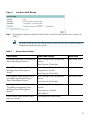
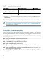
1
GETTING STARTED GUIDE
Cisco Aironet 1140 Series Autonomous Access Point
1
About this Guide
2
Safety Instructions
3
Overview
4
Obtaining and Assigning an IP Address
5
Mounting the Access Point
6
Configuring Basic Settings
7
Troubleshooting
8
Access Point Specifications
9
Obtaining Documentation and Submitting a Service Request
10 Declarations of Conformity and Regulatory Information
78-18997-01
1 About this Guide
This Guide explains how to install and configure your Cisco Aironet 1140 Series Autonomous Access
Point. This guide also provides mounting instructions and limited troubleshooting procedures.
2 Safety Instructions
Translated versions of the following safety warnings are provided in the translated safety warnings
document that is shipped with your access point. The translated warnings are also in the Translated
Safety Warnings for Cisco Aironet Access Points, which is available on your documentation CD and
cisco.com.
Warning
IMPORTANT SAFETY INSTRUCTIONS
This warning symbol means danger. You are in a situation that could cause bodily injury.
Before you work on any equipment, be aware of the hazards involved with electrical
circuitry and be familiar with standard practices for preventing accidents. Use the
statement number provided at the end of each warning to locate its translation in the
translated safety warnings that accompanied this device. Statement 1071
SAVE THESE INSTRUCTIONS
Warning
Read the installation instructions before you connect the system to its power source.
Statement 1004
Warning
This product must be connected to a Power-over-Ethernet (PoE) IEEE 802.3af compliant
power source or an IEC60950 compliant limited power source. Statement 353
Warning
This equipment must be externally grounded using a customer-supplied ground wire
before power is applied. Contact the appropriate electrical inspection authority or an
electrician if you are uncertain that suitable grounding is available. Statement 366
2
Warning
Installation of the equipment must comply with local and national electrical codes.
Statement 1074
Warning
This product relies on the building’s installation for short-circuit (overcurrent)
protection. Ensure that the protective device is rated not greater than:
20A. Statement 1005
Warning
Do not operate your wireless network device near unshielded blasting caps or in an
explosive environment unless the device has been modified to be especially qualified for
such use. Statement 245B
Warning
In order to comply with FCC radio frequency (RF) exposure limits, antennas should be
located at a minimum of 7.9 inches (20 cm) or more from the body of all persons.
Statement 332
Caution
When mounting the access point to a wall or ceiling, be sure to use appropriate fasteners.
The fasteners used must be capable of maintaining a minimum pullout force of 20 lbs (9
kg) and must use all 4 indented holes on the low-profile mounting bracket.
Caution
This product and all interconnected equipment must be installed indoors within the same
building, including the associated LAN connections as defined by Environment A of the
IEEE 802.af Standard.
Note
The access point is suitable for use in environmental air space in accordance with section
300.22.C of the National Electrical Code and sections 2-128, 12-010(3), and 12-100 of the
Canadian Electrical Code, Part 1, C22.1. You should not install the power supply or power
injector in air handling spaces.
Note
Use only with listed ITE equipment.
3
3 Overview
This section explains necessary tasks prior to installing the 1140 series access point.
Verifying Shipped Components
To unpack and verify the contents of the 1140 series access point and accessory kit, follow these steps:
Step 1
Unpack and remove the access point and the accessory kit from the shipping box.
Step 2
Return any packing material to the shipping container and save it for future use.
Step 3
Verify that you have received the items shown in Figure 1. If any item is missing or damaged,
contact your Cisco representative or reseller for instructions.
Figure 1
Shipping Box Contents
1
2
3
207439
4
4
1
Standard ceiling adjustable T-rail clip
3
1140 series access point
2
Mounting bracket
4
6-32 x 1/4 in. (0.63 cm) flat head screws
Key Ports and Components
Familiarize yourself with the access point before continuing with the installation. Figure 2 shows the
access point key components.
Figure 2
Access Point Ports and Connections
1
5
6
272377
6
2
3
4
1
Kensington lock slot
4
Console port
2
Power connection
5
Security padlock and hasp
3
Ethernet port
6
Low-profile mounting bracket pins (feet for
desk or table-top mount)
5
Performing a Site Survey
Before you mount and deploy your access point, we recommend that you perform a site survey (or use
a site planning tool) to determine the best location to install your access point.
You should have the following information about your wireless network available:
• Access point locations.
• Access point mounting options: below a suspended ceiling, on a flat horizontal surface, or on a
desktop.
Note
You can mount the access point above a suspended ceiling but you must purchase
additional mounting hardware: See the “Mounting the Access Point” section on page 9
for additional information.
• Access point power options: power supplied by a DC power supply, PoE from a network device,
or a PoE power injector/hub (usually located in a wiring closet).
Note
Access points mounted in a building’s environmental airspace must be powered using PoE
to comply with safety regulations.
Cisco recommends that you make a site map showing access point locations so that you can record the
device MAC addresses from each location and return them to the person who is planning or managing
your wireless network.
4 Obtaining and Assigning an IP Address
To browse to the access point Express Setup page, you must either obtain or assign the access point IP
address using one of these methods:
Note
The access point does not have a default IP address.
• Assign a static IP address by connecting to its console port and accessing the access point CLI.
• Use a DHCP server (if available) to automatically assign an IP address. You can find out the
DHCP-assigned IP address by using one of the following methods:
– Connect to the access point console port and use a Cisco IOS command to display the IP
address, such as show interface bvi1.
6
– Provide your organization’s network administrator with your access point MAC address.
Your network administrator will query the DHCP server using the MAC address to identify
the IP address. The MAC address is on a label attached to the bottom of the access point.
– Use the CLI and serial port to identify the assigned IP address.
Connecting to the Access Point Locally
If you need to configure the access point locally (without connecting it to a wired LAN), you can
connect a PC to its console port by using a DB-9 to RJ-45 serial cable.
Caution
Be careful when handling the access point, the bottom plate might be hot.
Follow these steps to open the CLI by connecting to the access point console port:
Step 1
Connect a nine-pin, female DB-9 to RJ-45 serial cable to the RJ-45 console port on the access
point and to the COM port on a computer.
Note
Step 2
The Cisco part number for the serial cable is AIR-CONCAB1200.
Set up a terminal emulator on your PC to communicate with the access point. Use the
following settings for the terminal emulator connection: 9600 baud, 8 data bits, no parity, 1
stop bit, and no flow control.
Assigning the IP Address to the BVI
When you assign an IP address to the access point by using the CLI, you must assign the address to
the bridge-group virtual interface (BVI). Beginning in a privileged EXEC mode, follow these steps to
assign an IP address to the access point BVI using the access point console port.
Step 1
Command
Purpose
configure terminal
Enter global configuration mode.
7
Command
Purpose
Step 2
interface bvi1
Enters interface configuration mode for the
BVI.
Step 3
ip address ip_address net_mask
Assigns an IP address and subnet mask
address to the BVI.
Assigning an IP Address Using the CLI
Follow these steps to access the CLI using a Telnet session. These steps are for a PC running Microsoft
Windows with a Telnet terminal application. Check your PC operating instructions for detailed
instructions.
Step 1
Select Start > Programs > Accessories > Telnet.
If Telnet is not listed in your Accessories menu, select Start > Run, type Telnet in the entry
field, and press Enter.
Step 2
When the Telnet window appears, click Connect and select Remote System.
Step 3
In the Host Name field, type the access point IP address and click Connect.
Note
If you are connected to the access point using a Telnet session, you lose your connection to
the access point when you assign a new IP address to the BVI. If you need to continue
configuring the access point using Telnet, use the new IP address to open another Telnet
session to the access point.
8
5 Mounting the Access Point
Cisco Aironet 3500, 1260, 1140, 1130, and 1040 series access points can be mounted in several
configurations, including on a suspended ceiling, on a hard ceiling or wall, on an elecrtical or network
box, and above a suspended ceiling. Click this URL to browse to complete access point mounting
instructions:
http://www.cisco.com/en/US/docs/wireless/access_point/mounting/guide/apmount.html
Note
Caution
The integrated antenna design of the 1140 series access point is designed for horizontal
surfaces, (table top and ceiling installations). When mounted to such surfaces, the integrated
antennas produce the best antenna radiation pattern. For advanced features such as voice,
location, and rogue access point detection, ceiling mounting is strongly recommended.
However, for smaller areas such as conference rooms, kiosks, transportation, and hot-spot
usage where the customer is concerned primarily with data coverage and not advanced
features, you can mount the unit on a wall using wall anchors.
Do not use plastic wall anchors or the keyhole slots on the mounting bracket for ceiling
installations. When mounting the access point on a hard ceiling, use four fasteners
capable of maintaining a minimum pullout force of 20 lbs (9 kg).
6 Configuring Basic Settings
Before you can configure basic settings, the access point and your PC needs an IP address. See the
“Obtaining and Assigning an IP Address” section on page 6.
Follow these steps to configure basic settings for the access point using the GUI Express Setup page.
Step 1
Open your browser, and enter the access point IP address in the address field. A username and
password screen appears.
Step 2
Enter the username Cisco and password Cisco. The username and password are case sensitive.
Step 3
Press Enter. The Summary Status page appears.
9
Step 4
10
If required, configure the power settings as described in the previous section. Otherwise, Click
Express Setup. The Express Setup page appears.
Step 5
Configure the settings using the following sections as a guide.
• Host Name—The host name (or system name) is a name for the access point that identifies
it on your network. The system name appears in the titles of the management system
pages.
• Configuration Server Protocol—This setting specifies how the access point obtains an IP
address.
– DHCP—IP address is automatically assigned by the network DHCP server.
– Static IP—The access point uses a static IP address that you enter in the IP address
field.
• IP Address—This setting assigns or changes the access point IP address. If DHCP is
enabled, the access point obtains its IP address from your network DHCP server. You can
assign a static IP address in this field.
• IP Subnet Mask—The IP subnet mask identifies the subnet on which the access point
resides. This subnet is provided by your network administrator. If DHCP is enabled, leave
this field blank.
11
• Default Gateway—The default gateway identifies the address the access point uses to
access another network. This gateway is provided by your network administrator. If
DHCP is enabled, leave this field blank.
• Web Server—This setting specifies the type of HTTP used to access the access point using
a web browser.
– Standard (HTTP)—Standard protocol used to transfer HTML using unencrypted
traffic between web browsers.
– Secure (HTTPS)—Protocol used to transfer secure data by using encrypted traffic to
and from the user by means of a Secure Socket Layer (SSL).
• SNMP Community—The SNMP Community setting identifies and sets attributes for the
Simple Network Management Protocol (SNMP) used to manage the network on which
the access point resides.
– Read-Only—Access point allows only SNMP read access.
– Read-Write—Access point allows read and write access.
Configuring the Radios
Your 1140 series access point includes two internal radios, which must be configured
individually in Express Setup. Select the role, optimization setting, and extension capabilities
for Radio0 (802.11N2.4GHz) and Radio1 (802.11N5GHz).
• Role in Radio Network—Determines what function each radio in the access point
performs in the wireless network.
– Access Point—Specifies that the unit operates as an access point connected to the
main Ethernet LAN network. In this mode, wireless clients associate to the access
point.
– Repeater—Specifies that the unit operates as a repeater access point not connected to
Ethernet LAN. In this mode, wireless clients associate to the access point.
– Root Bridge—Specifies that the unit operates as a root bridge and connects directly
to the main Ethernet LAN. In this mode, the unit accepts associations from other
Cisco Aironet non-root bridges and wireless client devices.
– Workgroup Bridge—Specifies that the unit operates as a workgroup bridge connected
to a small wired Ethernet LAN network through an Ethernet hub or switch. The
workgroup bridge must associate to a Cisco Aironet access point or bridge.
– Scanner—Specifies that the unit is configured by a Cisco WLSE and operates as a
scanner and reports network traffic to the Cisco WLSE.
• Optimize Radio Network For—Optimizes the access point radio performance in the
wireless network by adjusting data rates. This setting must match the setting on the
clients.
12
– Throughput—Maximizes data volume handled by the access point but might reduce
its range.
– Range—Maximizes the access point range but might reduce throughput.
– Default—The access point uses its default data rate settings for the radio selected.
– Custom—The access point uses settings that you enter on the radio settings page.
Clicking Custom takes you to the radio settings page.
• Aironet Extensions—By default, the access point uses Cisco Aironet 802.11 extensions to
detect the capabilities of Cisco Aironet client devices and to support features that require
specific interaction between the access point and associated client devices. Aironet
extensions must be enabled to support features such as load balancing, Message Integrity
Check (MIC), Temporal Key Integrity Check (TKIP), Repeater Mode, and World Mode.
Disabling Aironet Extensions disables the features mentioned above, but it sometimes
improves the ability of non-Cisco client devices to associate to the access point.
Default Settings on the Express Setup Page
Table 1 lists the default settings on the Express Setup page.
Table 1
Express Setup Default Settings
Setting
Default
System Name
ap
Configuration Server Protocol
DHCP
IP Address
Assigned by DHCP
Note
The access point does not have a default IP address.
IP Subnet Mask
Assigned by DHCP
Default Gateway
Assigned by DHCP
Role in Radio Network
Access point
Web Server
Standard (HTTP)
SNMP Community
default Community
Optimize Radio Network for
Throughput
Aironet Extensions
Enable
13
Note
You can restore the access point to its factory defaults by unplugging the power jack and
plugging it back in while holding the Mode button down until the Ethernet LED turns amber
(approximately 2 to 3 seconds).
Enabling the Radio Interfaces
The access point radios are disabled by default, and there is no default SSID. You must create an SSID
and enable the radios before the access point allows wireless associations from other devices. Refer to
the “Configuring Basic Security Settings” section on page 15 for instructions on configuring the SSID.
Follow these steps to enable the radio interfaces:
Step 1
Browse to your access point.
Step 2
When the Summary Status page appears, click 802.11N2.4GHz. The 2.4-GHz radio status page
appears.
Step 3
Choose the Settings tab at the top of the page. The Radio Settings page appears.
Step 4
Click Enable in the Enable Radio field.
Step 5
Click Apply.
Step 6
Return to the Summary Status page and click 802.11N5GHz. The 5-GHz radio status page
appears.
Step 7
Repeat Steps 3-5.
Step 8
Close your web browser.
Configuring Security Settings
After you assign basic settings to your access point, you must configure security settings to prevent
unauthorized access to your network. Because it is a radio device, the access point can communicate
beyond the physical boundaries of your work site.
Just as you use the Express Setup page to assign basic settings, you can use the Express Security page
to create unique SSIDs and assign one of four security types to them. For detailed security information,
refer to the Cisco IOS Software Configuration Guide for Cisco Aironet Access Points.
14
Configuring Basic Security Settings
You can use the Express Security page to create unique SSIDs and assign one of four security types to
them. This illustration shows the Express Security page.
Understanding Express Security Settings
When the access point configuration is set to factory defaults, the first SSID that you create by using
the Express Security page overwrites the default SSID, which has no security settings. The SSIDs that
you create appear in the SSID table at the bottom of the page. You can create up to 16 SSIDs on the
access point.
Using VLANs
If you use VLANs on your wireless LAN and assign SSIDs to VLANs, you can create multiple SSIDs
by using any of the four security settings on the Express Security page. However, if you do not use
VLANs on your wireless LAN, the security options that you can assign to SSIDs are limited because
of the limited Express Security page encryption options. Without VLANs, encryption settings (WEP
and ciphers) apply to an interface, such as the radio, and you cannot use more than one encryption
setting on an interface. For example, when you create an SSID with static WEP with VLANs disabled,
15
you cannot create additional SSIDs with WPA authentication because they use different encryption
settings. If you find that the security setting for an SSID conflicts with another SSID, you can delete
one or more SSIDs to eliminate the conflict.
If any VLANs are defined on the access point, the trunk port on the switch must be limited to allow
only the VLANs defined on the access point.
Express Security Types
There are four security types you can assign to an SSID:
• No security—The least secure option. Use this option only for SSIDs used in a public space, and
assign it to a VLAN that restricts access to your network.
• Static WEP Key—More secure than no security. Static WEP keys are vulnerable to attack. There
are two different lengths for WEP keys: 40-bit and 128-bit (hexadecimal or ASCII characters).
Cisco access points use hexadecimal characters. Client adapters can use either, depending on how
the vendor chooses to configure them.
• EAP Authentication—Enables 802.1x authentication. Requires an IP address and shared secret
from an authentication server on your network (server authentication port 1645). You do not need
to enter a WEP key.
• WPA—Wi-Fi Protected Access (WPA) permits wireless access to users authenticated against a
database through the services of an authentication server and encrypts their IP traffic with
stronger algorithms than those used in WEP. As with EAP authentication, you must enter the IP
address and shared secret for an authentication server on your network (server authentication port
1645).
Configuring Security for 802.11n
To achieve 802.11n speeds, you need to configure the access point for no encryption or WPA2/AES
encryption. Any other setting eliminates 802.11n capabilities from the configuration.
Express Security Limitations
Because the Express Security page is designed for simple configuration of basic security, the options
available are a subset of the access point security capabilities. Keep these limitations in mind when
using the Express Security page:
• You cannot edit SSIDs. However, you can delete SSIDs and recreate them.
• You cannot assign SSIDs to specific radio interfaces. The SSIDs that you create are enabled on all
radio interfaces. To assign SSIDs to specific radio interfaces, choose Security > SSID Manager.
• You cannot configure multiple authentication servers. To configure multiple authentication
servers, click Security > Server Manager.
16
• You cannot configure multiple WEP keys. To configure multiple WEP keys, click Security >
Encryption Manager.
• You cannot assign an SSID to a VLAN that is already configured on the access point. To assign an
SSID to an existing VLAN, choose Security > SSID Manager.
• You cannot configure combinations of authentication types on the same SSID (such as MAC
address authentication and EAP authentication). To configure combinations of authentication
types, choose Security > SSID Manager.
Using the Express Security Page
Follow these steps to create an SSID using the Express Security page:
Step 1
Type the SSID in the SSID entry field. The SSID can contain up to 32 alphanumeric characters.
Note
Step 2
These characters are not allowed in the SSID: +, ], /, “, TAB, and trailing SPACE.
To broadcast the SSID in the access point beacon, check the Broadcast SSID in Beacon check
box.
Note
When you broadcast the SSID, devices that do not specify an SSID can associate to
the access point. This is a useful option for an SSID used by guests or client devices
in public space. If you do not broadcast the SSID, client devices cannot associate to
the access point unless their SSID matches this SSID, so only one SSID can be included
in the access point beacon.
Step 3
(Optional) Check the Enable VLAN ID check box and enter a VLAN number (1 through
4095) to assign the SSID to a VLAN. You cannot assign an SSID to an existing VLAN.
Step 4
(Optional) Check the Native VLAN check box to mark the VLAN as the native VLAN.
Step 5
Select the security setting for the SSID. The settings are listed in order of their robustness, from
No Security to WPA, which is the most secure setting.
a. If you select Static WEP Key, choose the key number and encryption size and enter the
encryption key (10 hexadecimal characters for 40-bit keys or 26 hexadecimal characters for
128-bit keys.
b. If you select EAP Authentication or WPA, enter the IP address and shared secret for the
authentication server on your network.
c. Your 802.11n security configuration must be either no encryption or WPA2/AES. Any other
configuration eliminates the higher data speeds provided by 802.11n.
17
If you do not use VLANS on your wireless LAN, the security options that you can assign to
multiple SSIDs are limited. Refer to the Cisco IOS Software Configuration Guide for Cisco
Aironet Access Points for VLAN details.
Note
1. Click Apply. The SSID appears in the SSID table at the bottom of the page.
7 Troubleshooting
This section offers some diagnostic and configuration suggestions for troubleshooting your access
point.
Checking the Access Point LED
Figure 3 shows the location of the access point Status LED.
Figure 3
Access Point LED Location
272378
1
1
18
Status LED
Note
Regarding LED status colors, it is expected that there will be small variations in color intensity
and hue from unit to unit. This is within the normal range of the LED manufacturer’s
specifications and is not a defect.
Table 2 shows the access point LED diagnostics for various conditions.
Table 2
Access Point LED Diagnostic Messages
Message Type
Status LED
Message Meaning
Boot loader status
sequence
Blinking green
DRAM memory test in progress
DRAM memory test OK
Board initialization in progress
Initializing FLASH file system
FLASH memory test OK
Initializing Ethernet
Ethernet OK
Starting Cisco IOS
Initialization successful
Association status
Operating status
Boot loader warnings
Green
Normal operating condition, but no wireless
client associated
Blue
Normal operating condition, at least one wireless
client association
Blinking blue
Software upgrade in progress
Rapidly cycling
through blue, green,
red, and white
Access point location command invoked
Blinking blue
Configuration recovery in progress (MODE
button pushed for 2 to 3 seconds)
Red
Ethernet failure or image recovery (MODE
button pushed for 20 to 30 seconds)
Blinking green
Image recovery in progress (MODE button
released)
Blinking red
Ethernet link not operational
19
Table 2
Access Point LED Diagnostic Messages (continued)
Message Type
Status LED
Message Meaning
Boot loader errors
Red
DRAM memory test failure
Blinking red and blue
FLASH file system failure
Blinking red and off
Environment variable failure
Bad MAC address
Ethernet failure during image recovery
Boot environment failure
No Cisco image file
Boot failure
Cisco IOS errors
Red
Software failure; try disconnecting and
reconnecting unit power
Cycling through blue,
green, red, and off
General warning; insufficient inline power
Configuring System Power Settings
After connecting the access point to a power source, its status LED might be amber, which can indicate
that the access point is unable to verify that the power source equipment (PSE) is supplying sufficient
power. In such cases, you need to configure settings on the access point or the switch to identify your
power source.
Identify your power source and switch condition, and then make sure that your devices are configured
with an IP address.
Follow these steps to configure the system power settings using the GUI:
Step 1
Open your browser and enter the access point IP address in the address field. A login and
password screen appears.
Step 2
Enter the username Cisco and password Cisco. The username and password are case sensitive.
Step 3
When the access point does not receive enough power for full operations, it is in low power
mode. If your access point is in low power mode, a warning message appears indicating that
all radios are disabled due to insufficient power. Click OK to continue. The System
Configuration page appears.
Step 4
Scroll down to the System Power Settings section as shown in Figure 4.
20
Figure 4
Step 5
Low Power Mode Warning
Set the power settings and power injector fields, and verify your switch status as shown in
Table 3.
Note
Table 3
To verify switch status, you need to use the switch CLI. See the Cisco IOS software
configuration guide for your switch.
System Power Settings
Power Source
System Power Settings
Switch Status
Cisco PSE supporting Cisco Intelligent
Power Management feature1
Power Settings: Power Negotiation
selected
power inline auto
Power Injector: Unchecked
Cisco PSE not supporting Cisco
Intelligent Power Management
feature1
Power Settings: Prestandard
Compatibility selected
Cisco Aironet Power Injector with a
Cisco PSE supporting Intelligent
Power Management feature1
Power Settings: Power Negotiation
selected
Cisco Aironet Power Injector with a
Cisco PSE not supporting Cisco
Intelligent Power Management
feature1
Power Settings: Power Negotiation
selected
Cisco Aironet Power Injector with a
non-Cisco switch
No configuration requirement
power inline auto
Power Injector: Unchecked
power inline never
Power Injector: Unchecked
power inline never
Power Injector: Checked
MAC address2
21
Table 3
System Power Settings (continued)
Power Source
System Power Settings
802.3af-compliant switch that does
not support Cisco inline power
(non-Cisco switch)
No configuration requirement
AC power adapter
No configuration requirement
1.
2.
Switch Status
Check the release notes for your power sourcing equipment to determine which Cisco IOS version supports Cisco Intelligent Power
Management. For some PSEs, support for Cisco Intelligent Power Management might not be available yet.
MAC address is the 12- character hexadecimal address of the switch port to which the access point is attached. The MAC address format is
HHHH.HHHH.HHHH.
Step 6
Click Apply. The access point reboots configured with the power settings you specified.
Note
You might have to refresh your browser screen to see the current status indicating that the
access point radios are enabled.
Finding More Troubleshooting Help
If you are still experiencing difficulty, before contacting Cisco, look for a solution to your problem in
this guide or the troubleshooting chapter of the hardware installation guide for the access point you
are using. These, and other documents, are available on Cisco.com. Follow these steps to access and
download these documents:
Step 1
Open your web browser and go to http://www.cisco.com.
Step 2
Click Products & Services. A pop-up window appears.
Step 3
Click Wireless. The Wireless Introduction page appears.
Step 4
Scroll down to the Product Portfolio section.
Step 5
Under Access Points, click Cisco Aironet 1140 Series. The Cisco Aironet 1140 Series
Introduction page appears.
Step 6
Scroll down to the Support window and click Install and Upgrade. The Cisco Aironet 1140
Series Install and Upgrade page appears.
Step 7
Click Install and Upgrade Guides. The Cisco Aironet 1140 Series Install and Upgrade Guides
page appears.
22
Step 8
Select the section that best suits your troubleshooting needs.
8 Access Point Specifications
Table 4 lists the technical specifications for the 1140 series autonomous access point.
Table 4
Access Point Specifications
Category
Specification
Dimensions (LxWxD)
8.68 x 8.68 x 1.84 in. (22.04 x 22.04 x 4.67 cm)
Weight
1.9 lbs (0.86 kg)
Operating temperature
32 to 104 degrees F (0 to –40 degrees C)
Storage temperature
–22 to 185 degrees F (–30 to 85 degrees C)
Humidity
10% to 90% (noncondensing)
Antenna
Integrated
Compliance
The 1140 series access point complies with UL 2043 for products installed
in a building’s environmental air handling spaces, such as above suspended
ceilings.
Safety
UL 60950-1
CAN/CSA C22.2 No. 60950-1
IEC 60950-1 with all national deviations
EN 60950-1
UL 2043
EMI and Susceptibility
FCC Part 15.107 and 15.109 Class B
ICES-003 Class B (Canada)
EN 301.489
EN 55022 Class B, 2000 version
EN 55024
AS/NZS 3548 Class B
VCCI Class B
23
Table 4
Access Point Specifications (continued)
Category
Specification
Radio
FCC Part 15.247, 15.407
Canada RSS-210
Japan Telec 33, 66, T71
EN 330.328, EN 301.893
FCC Bulletin OET-65C
Industry Canada RSS-102
Maximum power and
channel settings
Maximum power and the channels allowed in your regulatory domain,
refer to Channels and Maximum Power Settings for Cisco Aironet
Lightweight Access Points. This document is available on cisco.com.
9 Obtaining Documentation and Submitting a Service
Request
For information on obtaining documentation, submitting a service request, and gathering additional
information, see the monthly What’s New in Cisco Product Documentation, which also lists all new
and revised Cisco technical documentation, at:
http://www.cisco.com/en/US/docs/general/whatsnew/whatsnew.html
Subscribe to the What’s New in Cisco Product Documentation as a Really Simple Syndication (RSS) feed
and set content to be delivered directly to your desktop using a reader application. The RSS feeds are a free
service and Cisco currently supports RSS Version 2.0.
10 Declarations of Conformity and Regulatory Information
This section provides declarations of conformity and regulatory information for the Cisco Aironet
1140 Series Autonomous Access Point.
24
Manufacturers Federal Communication Commission Declaration of
Conformity Statement
Tested To Comply
With FCC Standards
FOR HOME OR OFFICE USE
Models
Certification Numbers
AIR-AP1141N-A-K9
LDK102069
AIR-AP1142N-A-K9
LDK102070
Manufacturer:
Cisco Systems, Inc.
170 West Tasman Drive
San Jose, CA 95134-1706
USA
This device complies with Part 15 rules. Operation is subject to the following two conditions:
1. This device may not cause harmful interference, and
2. This device must accept any interference received, including interference that may cause undesired
operation.
This equipment has been tested and found to comply with the limits of a Class B digital device,
pursuant to Part 15 of the FCC Rules. These limits are designed to provide reasonable protection
against harmful interference when the equipment is operated in a residential environment. This
equipment generates, uses, and radiates radio frequency energy, and if not installed and used in
accordance with the instructions, may cause harmful interference. However, there is no guarantee that
interference will not occur. If this equipment does cause interference to radio or television reception,
which can be determined by turning the equipment off and on, the user is encouraged to correct the
interference by one of the following measures:
• Reorient or relocate the receiving antenna.
• Increase separation between the equipment and receiver.
• Connect the equipment to an outlet on a circuit different from which the receiver is connected.
• Consult the dealer or an experienced radio/TV technician.
25
Caution
The Part 15 radio device operates on a non-interference basis with other devices operating
at this frequency when using the integrated antennas. Any changes or modification to the
product not expressly approved by Cisco could void the user’s authority to operate this
device.
Caution
Within the 5.15 to 5.25 GHz band (5 GHz radio channels 34 to 48) the UNII devices are
restricted to indoor operations to reduce any potential for harmful interference to
co-channel Mobile Satellite System (MSS) operations.
VCCI Statement for Japan
Warning
This is a Class B product based on the standard of the VCCI Council. If this is
used near a radio or television receiver in a domestic environment, it may
cause radio Interference. Install and use the equipment according to the
instruction manual.
VCCI-B
26
Guidelines for Operating Cisco Aironet Access Points in Japan
This section provides guidelines for avoiding interference when operating Cisco Aironet access points
in Japan. These guidelines are provided in both Japanese and English.
03-6434-6500
43768
Japanese Translation
English Translation
This equipment operates in the same frequency bandwidth as industrial, scientific, and medical devices
such as microwave ovens and mobile object identification (RF-ID) systems (licensed premises radio
stations and unlicensed specified low-power radio stations) used in factory production lines.
1. Before using this equipment, make sure that no premises radio stations or specified low-power
radio stations of RF-ID are used in the vicinity.
2. If this equipment causes RF interference to a premises radio station of RF-ID, promptly change
the frequency or stop using the device; contact the number below and ask for recommendations
on avoiding radio interference, such as setting partitions.
3. If this equipment causes RF interference to a specified low-power radio station of RF-ID, contact
the number below.
Contact Number: 03-6434-6500
27
Statement 371—Power Cable and AC Adapter
English Translation
When installing the product, please use the provided or designated connection cables/power cables/AC
adaptors. Using any other cables/adaptors could cause a malfunction or a fire. Electrical Appliance and
Material Safety Law prohibits the use of UL-certified cables (that have the “UL” shown on the code)
for any other electrical devices than products designated by CISCO. The use of cables that are certified
by Electrical Appliance and Material Safety Law (that have “PSE” shown on the code) is not limited
to CISCO-designated products.
Industry Canada
Canadian Compliance Statement
AIR-AP1141N-E-K9
2461B-102069
AIR-AP1142N-E-K9
2461B-102070
This Class B Digital apparatus meets all the requirements of the Canadian Interference-Causing
Equipment Regulations.
Cet appareil numerique de la classe B respecte les exigences du Reglement sur le material broilleur du
Canada.
This device complies with Class B Limits of Industry Canada. Operation is subject to the following
two conditions:
1. This device may not cause harmful interference, and
2. This device must accept any interference received, including interference that may cause undesired
operation.
28
Cisco Aironet Access Points are certified to the requirements of RSS-210. The use of this device in a
system operating either partially or completely outdoors may require the user to obtain a license for
the system according to the Canadian regulations. For further information, contact your local Industry
Canada office.
European Community, Switzerland, Norway, Iceland, and
Liechtenstein
Models:
AIR-AP1141N-E-K9
AIR-AP1142N-E-K9
The following standards were applied:
• Radio—EN 300.328-1, EN 300.328-2, EN 301.893
• EMC—EN 301.489-1, EN 301.489-17
• Safety—EN 60950-1
Note
This equipment is intended to be used in all EU and EFTA countries. Outdoor use may be
restricted to certain frequencies and/or may require a license for operation. For more details,
contact Cisco Corporate Compliance.
The following CE mark is affixed to the access point with a 2.4-GHz radio and a 54-Mb/s, 5-GHz
radio:
29
Declaration of Conformity with Regard to the R&TTE Directive 1999/5/EC
30
31
Declaration of Conformity for RF Exposure
United States
This system has been evaluated for RF exposure for Humans in reference to ANSI C 95.1 (American
National Standards Institute) limits. The evaluation was based on ANSI C 95.1 and FCC OET Bulletin
65C rev 01.01. The minimum separation distance from the antenna to general bystander is 7.9 inches
(20cm) to maintain compliance.
Canada
This system has been evaluated for RF exposure for Humans in reference to ANSI C 95.1 (American
National Standards Institute) limits. The evaluation was based on RSS-102 Rev 2. The minimum
separation distance from the antenna to general bystander is 7.9 inches (20cm) to maintain
compliance.
European Union
This system has been evaluated for RF exposure for Humans in reference to the ICNIRP (International
Commission on Non-Ionizing Radiation Protection) limits. The evaluation was based on the EN
50385 Product Standard to Demonstrate Compliance of Radio Base stations and Fixed Terminals for
Wireless Telecommunications Systems with basic restrictions or reference levels related to Human
Exposure to Radio Frequency Electromagnetic Fields from 300 MHz to 40 GHz. The minimum
separation distance from the antenna to general bystander is 20cm (7.9 inches).
Australia
This system has been evaluated for RF exposure for Humans as referenced in the Australian Radiation
Protection standard and has been evaluated to the ICNIRP (International Commission on
Non-Ionizing Radiation Protection) limits. The minimum separation distance from the antenna to
general bystander is 20cm (7.9 inches).
Administrative Rules for Cisco Aironet Access Points in Taiwan
This section provides administrative rules for operating Cisco Aironet access points in Taiwan. The
rules for all access points are provided in both Chinese and English.
32
Chinese Translation
English Translation
Administrative Rules for Low-power Radio-Frequency Devices
Article 12
For those low-power radio-frequency devices that have already received a type-approval, companies,
business units or users should not change its frequencies, increase its power or change its original
features and functions.
Article 14
The operation of the low-power radio-frequency devices is subject to the conditions that no harmful
interference is caused to aviation safety and authorized radio station; and if interference is caused, the
user must stop operating the device immediately and can't re-operate it until the harmful interference
is clear.
The authorized radio station means a radio-communication service operating in accordance with the
Communication Act.
The operation of the low-power radio-frequency devices is subject to the interference caused by the
operation of an authorized radio station, by another intentional or unintentional radiator, by
industrial, scientific and medical (ISM) equipment, or by an incidental radiator.
33
Chinese Translation
Operation of Cisco Aironet Access Points in Brazil
This section contains special information for operation of Cisco Aironet access points in Brazil.
Access Point Models
AIR-AP1142N-T-K9
AIR-AP1141N-A-K9
34
Regulatory Information
Figure 5 contains Brazil regulatory information for the access point models identified in the previous
section.
Figure 5
Brazil Regulatory Information
Portuguese Translation
Este equipamento opera em caráter secundário, isto é, não tem direito a proteção contra interferência
prejudicial, mesmo de estações do mesmo tipo, e não pode causar interferência a sistemas operando
em caráter primário.
English Translation
This equipment operates on a secondary basis and consequently must accept harmful interference,
including interference from stations of the same kind. This equipment may not cause harmful
interference to systems operating on a primary basis.
35
Americas Headquarters
Cisco Systems, Inc.
San Jose, CA
Asia Pacific Headquarters
Cisco Systems (USA) Pte. Ltd.
Singapore
Europe Headquarters
Cisco Systems International BV
Amsterdam, The Netherlands
Cisco has more than 200 offices worldwide. Addresses, phone numbers, and fax numbers are listed on the
Cisco Website at www.cisco.com/go/offices.
Cisco and the Cisco Logo are trademarks of Cisco Systems, Inc. and/or its affiliates in the U.S. and other countries. A listing of Cisco's
trademarks can be found at www.cisco.com/go/trademarks. Third party trademarks mentioned are the property of their respective
owners. The use of the word partner does not imply a partnership relationship between Cisco and any other company. (1005R)
© 2010 Cisco Systems, Inc. All rights reserved.
78-18997-01