1
The Chamberlain Group, Inc.
A DUCHOSSOIS ENTERPRISE
845 Larch Avenue, Elmhurst, Illinois 60126-1196
Garage Door Opener
Owner's Manual
FOR RESIDENTIAL USE ONLY
SERIES 5000-1/2HP
SERIES 2000- 1/3HP
SERIES 4000 & 700 WHC -1/2HP
SERIES 1000- 1/4HP
CAUTION! PLEASE READ THIS MANUAL CAREFULLY
The MODEL NUMBER label is located on the front panel of your opener.
THIS DEVICE COMPLIES WITH FCC RULES PART 15. Operation of this device is subject to the following two conditions: 1. This device may
not cause harmful interference. 2. This device must accept any interference that may be received, including interference that may Cause
undesired operation
CONTENTS
PAGE
Safety Rules............................................................................... 2
Features of Your Opener ........................................................... 3
Specifications ............................................................................ 3
Tools You'll Need ...................................................................... 3
Completed Installation Illustrations ............................................ 4
Operation of Your Opener .......................................................... 5
Accessories .............................................................................. 5
Care & Maintenance of Your Opener ........................................ 6
Assembly Instructions................................................................ 7
Installation Instructions.............................................................. 10
Travel Limit Adjustments .......................................................... 20
PAGE
CONTENTS
Force Adjustments .................................................................... 21
Safety Reverse Test ................................................................. 22
The Protector System Accessory ............................................. 22
Setting/Changing Code ............................................................. 23
Having A Problem? ................................................................... 24
Carton Contents & Hardware Illustrated ................................... 26
Repair Parts, Rail Assembly ..................................................... 26
Repair Parts, Installation.............................................................26
Repair Parts, Chassis Assembly .............................................. 27
How to Order Repair Parts ........................................................28
Warranty ...................................................................................28
FASTEN THIS MANUAL NEAR THE GARAGE DOOR AFTER INSTALLATION.
PERIODIC CHECKS OF THE OPENER ARE REQUIRED TO INSURE SATISFACTORY OPERATION.
ADJUSTMENT STEP 1
Adjust UP and DOWN Limits
LIMIT ADJUSTMENT settings regulate the points at which
the door will stop when moving up or down.
NOTE: Door STOPS In the UP direction If anything
interferes with door travel. Door REVERSES in the
DOWN direction It anything interferes with the door
travel (including binding or unbalanced doors).
PROCEDURE: To operate the opener, press the Door
Control Button. Run the opener through a COMPLETE
TRAVEL CYCLE. No limit adjustments are necessary
when the door opens and closes completely and doesn't
reverse unintentionally when fully closed.
The following chart outlines adjustment procedures. Run the opener through a COMPLETE TRAVEL
CYCLE AFTER EACH ADJUSTMENT.
NOTE: REPEATED OPERATION OF THE OPENER DURING ADJUSTMENT PROCEDURES MAY CAUSE
MOTOR TO OVERHEAT AND SHUT OFF. SIMPLY WAIT 15 MINUTES AND TRY AGAIN.
Read the chart carefully before proceeding to Step 2. Use a screwdriver to make limit adjustments.
___________________________________________________________________________________________________
LIMIT ADJUSTMENT CHART
IF OPENER REVERSES IN FULLY
CLOSED POSITION
IF DOOR DOES NOT OPEN COMPLETELY
BUT OPENS AT LEAST FIVE FEET
Decrease DOWN travel. Turn down limit adjustment
screw clockwise. One turn equals 2 inches of travel.
Increase UP travel. Turn the UP LIMIT adjustment screw
clockwise. One turn equals 2" of travel.
If door does not open at least 5 feet: adjust UP (OPEN)
FORCE as explained in Step 2.
IF DOOR REVERSES WHEN CLOSING AND THERE
IS NO INTERFERENCE TO TRAVEL CYCLE
Test door for binding: Pull manual release handle.
Manually open and close door. If door is binding, call for
garage door service. If door is not binding or unbalanced,
adjust DOWN (CLOSE) FORCE. See Step 2.
IF DOOR DOES NOT CLOSE COMPLETELY
Increase DOWN travel. Turn down limit adjustment
screw counterclockwise. One turn equals 2" of travel.
If the door still will not close completely, the header
bracket is positioned too high. See Step 1, page 10.
20
ADJUSTMENT STEP 2
DO NOT USE FORCE ADJUSTMENTS TO
COMPENSATE FOR A BINDING OR STICKING
GARAGE DOOR. EXCESSIVE FORCE WILL
Adjust Force
INTERFERE WITH PROPER OPERATION OF SAFETY
REVERSE SYSTEM OR DAMAGE GARAGE DOOR.
Force Adjustment Controls are located on rear panel of
opener. FORCE ADJUSTMENT settings regulate
amount of the power required to open and close door.
NOTE: The door STOPS in the UP direction if
anything Interferes with its travel. Door REVERSES
In the DOWN direction If anything interferes with Its
travel (Including binding or unbalanced doors).
If the force adjustments are set too light, door travel may
be interrupted by nuisance reversals in DOWN direction
and stops in UP direction. Weather conditions can affect
the door movement, occasional adjustment may be
needed.
Maximum force adjustment range is 260 degrees, about
3/4 of a complete turn. Do not force controls beyond
that point. Turn force adjustment controls with a
screwdriver.
Adjustment Label
___________________________________________________________________________________________________
FORCE ADJUSTMENT CHART
IF DOOR DOESN'T OPEN AT LEAST 5 FEET
TEST DOWN (CLOSE) FORCE
Grasp the door handle or door bottom when door is
about halfway through DOWN (CLOSE) TRAVEL. Door
should reverse. If the door is hard to hold or doesn't
reverse, decrease DOWN (CLOSE) FORCE by turning
the control in a counterclockwise direction. Make 10
degree turn adjustments until door reverses normally.
After each adjustment, run opener through a complete
cycle.
Increase UP (OPEN) FORCE by turning the control in a
clockwise direction. Make 10 degree turn adjustments
until door opens completely. Readjust UP LIMIT if
necessary. After each adjustment, run opener through a
complete travel cycle.
IF DOOR REVERSES DURING DOWN
{CLOSE) CYCLE
Increase DOWN (CLOSE) FORCE by turning control
clockwise Make 10 degree turn adjustments until door
completes close cycle. After each adjustment, run the
opener through a complete travel cycle.
PROCEED TO STEP 3
21
ADJUSTMENT STEP 3
THE SAFETY REVERSE SYSTEM TEST IS
_
IMPORTANT.
GARAGE DOOR MUST
REVERSE ON CONTACT WITH A ONE-INCH
Test Safety Reverse System
OBSTACLE PLACED ON THE FLOOR. FAILURE TO
PROPERLY ADJUST OPENER MAY RESULT IN SERIOUS
PERSONAL INJURY FROM A CLOSING GARAGE DOOR.
REPEAT TEST ONCE A MONTH AND ADJSUT AS NEEDED.
PROCEDURE: Place a one-inch obstacle on the floor
under the garage door. Operate door in DOWN direction.
The door MUST reverse on the obstruction.
If the door STOPS on the obstruction, it is not traveling
far enough in the DOWN direction. Increase the DOWN
limit by turning DOWN limit adjustment screw
counterclockwise 1/4 turn. REPEAT TEST.
NOTE: Make sure limit adjustments do not force the
door arm beyond a straight up and down position.
See the Illustration on Page 18/19.
When the door reverses on the one-inch obstacle,
remove the obstruction and run the opener through a
complete travel cycle
Door MUST NOT reverse in closed position. Repeat
Adjustment Steps 1, 2 and 3 if necessary.
REPEAT ADJUSTMENT STEP 3 AFTER:
•
EACH ADJUSTMENT OF DOOR ARM LENGTH, CLOSE
•
FORCE OR DOWN LIMIT.
ANY REPAIR OR ADJUSTMENT OF GARAGE DOOR
(INCLUDING SPRINGS AND HARDWARE).
•
ANY REPAIR OR BUCKLING OF THE GARAGE FLOOR.
•
ANY REPAIR OR ADJUSTMENT OF THE GARAGE
DOOR OPENER.
______________________________________________________________________________________________________
THE
PROTECTOR
SYSTEM
PROVIDES
AN
ADDITIONAL MEASURE OF SAFETY AGAINST A
SMALL CHILD BEING CAUGHT UNDER A GARAGE
DOOR. It uses an Invisible beam which, when broken by
an obstruction, causes a closing door to open and
prevents an open door from closing. STRONGLY
RECOMMENDED FOR HOMEOWNERS WITH YOUNG
CHILDREN.
THE PROTECTOR SYSTEM
Installation of Optional Safety Feature
After opener has been installed and adjusted,
THE PROTECTOR SYSTEM accessory can
be installed.
Instructions are included with this optional
device.
22
ACTIVATE THE OPENER ONLY WHEN
DOOR IS IN FULL VIEW, FREE OF
OBSTRUCTION AND PROPERLY
ADJUSTED. NO ONE SHOULD ENTER OR LEAVE
GARAGE WHILE DOOR IS IN MOTION. DO NOT
ALLOW CHILDREN TO OPERATE REMOTES OR
DOOR CONTROL BUTTONS. DO NOT ALLOW
CHILDREN TO PLAY NEAR THE DOOR.
Radio Controls
F.C.C. rules prohibit adjustments to or modification of receiver and/or
remote control transmitter circuitry except for changing code setting and
replacing remote control transmitter battery. NO USER SERVICEABLE
PARTS.
Manufactured under 1 or more of the following U.S. patents: RE29,525;4,037.201;
4.750.118; 4.806.930
Other Patents Pending.
Your garage door opener receiver and remote control transmitter have been factory set to a matching
code. Models having multi-function remote controls will activate when LARGE button on remote is pressed. If you want to
CHANGE your code or purchase additional remotes, follow the Instructions below. The code in any NEW remote control
must be set to match the code In the original remote control.
MATCH/CHANGE THE CODE IN REMOTE CONTROL(S)
Slide battery compartment cover back to access code switches in your remote control and any new remote. Place
remotes side by side as shown. Use a pen or screwdriver to slide the switches to (+,-,0) positions.
Multi- FunctionRemotes: Set code switches 2 through 9 in ALL remotes to matching positions. Code switch 1 in a multifunction remote is neutral. It can be set to any position.
Single Function Remotes: Set code switched 1 through 9 to matching positions.
Combination of Single and Multi-Function Remotes: Set code switches 2 through 9 to match. Set single functon remote
code switch 1 to match positin of selected push button on multi-function remote (Figure B).
Single-Function Remote Control
Multi-Function Remote Control
When used with multi-function remote, set single
function remote Code Switch #1 to match push button
selected on multi-function remote. (See illustration
below.)
Code Switch #1 in a multi-function remote is neutral set it
to any position.
MATCH/CHANGE THE CODE IN THE RECEIVER
"SMART"GARAGE DOOR OPENERS
Set all remotes to matching code settings as shown
above. Select a push button to operate the door opener.
MULTI-FUNCITON REMOTE CONTROL ONLY:
Select a push button to operate receiver. LARGE button
is reccommended for garage door opener.
YOU MAY WANT SOMEONE TO HELP AT THIS POINT!
1. Press and HOLD the selected remote control push
button.
2. Then press the receiver ‘Smart’ button on the back panel
of the opener. The adjacent indicator light will FLASH
and the door will begin to MOVE. Release the remote
control push button.
The opener will now operate when either the door control
push button or the transmitter push button is pressed.
NOTE: If the transmitter push button is not held down
until the receiver indicator light flashes, the receiver
will not learn the code.
To use the multi-function remote control with other ‘Smart’
receivers: Select another remote push button to operate
additional garage door opener. All remotes used to
operatereceiver must be set to same code. Then repeat
above procedure.
To use the multi-function remote with light
products and garage door openerts having ‘Code
Switch’ receivers, refer to instructions included
with the product.
23
Repair Parts
INSTALLATION HARDWARE
ASSEMBLY HARDWARE
1
2
RAIL ASSEMBLY PARTS
INSTALLATION PARTS
12
13
14
4
3
5
16
15
6
8
19
18
17
7
21
10
22
9
11
20
26
23
24
25
Repair Parts
Chassis Assembly Parts List
KEY
NO.
1
2
PART
NO.
31C290
41A2827
3
41A2817
4
5
42B2991
143D100
143D123
175B88
108D36
108D34
30B363
30B387
30B366
12A373
41A3150
6
7
8
9
10
KEY
NO.
DESCRIPTION
Sprocket cover
Gear and sprocket assy.
Complete with:
Spring washer
Thrust washer
Retaining ring
Bearing plate
Roll pins (2)
Drive gear
Worm gear
Helical gear w/retainer
Grease
Drive/worm gear kit w/grease
Roll pins (2)
Line cord
End panel (Models 2000 & 1000)
End panel (All other models)
Light socket
Lens (Model 2000)
Lens (Models 5000, 4000-2, 4000)
Capacitor- 1/2HP
Capacitor- 1/3HP
Capacitor- 1/4HP
Capacitor bracket
Terminal block w/screws
11
12
13
14
15
16
17
18
19
20
PART
NO.
41 D3058
41A3666
41A3666-1
41A3666-2
41A3666-3
41A2818
41D3452
41C3005
41C2726
41A2826
41A2822
41A3626
41A3627
41A3673
41A3712
41A2825
27
DESCRIPTION
Universal replacement motor /bracket assy.
(Includes motor, worm, bracket, bearing assy.
and RPM sensor)
Cover (Model 5000)
Cover (Models 4000-2, 4000, 700WHC) Cover
(Model 2000)
Cover (Model 1000)
Helical gear & retainer w/grease
Limit switch assembly
RPM sensor assembly
Wire harness assy. w/plug
Shaft bearing kit
Interrupter cup assy.
Receiver logic board assy. (Model 5000)
Receiver logic board assy. (All other models)
Complete with: Logic board End panel w/all
labels End panel w/all labels (Model 5000) End
panel w/all labels (All other models)
End panel w/all labels (Model 5000)
End panel w/all labels (All other models)
NOT SHOWN
Chassis assy. hdwe. kit (includes screws not
designated by number in illustration)
HOW TO ORDER
REPAIR PARTS
CHAMBERLAIN SERVICE
IS ON CALL
OUR LARGE SERVICE ORGANIZATION
SPANS AMERICA
INSTALLATION AND SERVICE INFORMATION IS AS
NEAR AS YOUR TELEPHONE SIX DAYS A WEEK. SIMPLY
DIAL OUR TOLL FREE NUMBER:
Selling prices will be furnished on request or parts will be
shipped at prevailing prices and you will be billed accordingly.
WHEN ORDERING REPAIR PARTS, ALWAYS GIVE THE
FOLLOWING INFORMATION:
• PART NUMBER
• PART NAME
• MODEL NUMBER
1-800-528-9131
ADDRESS ORDERS TO:
THE CHAMBERLAIN GROUP, INC.
Electronic Parts and Service Department
2106 N. Forbes Boulevard
Tucson, Arizona 85745
HOURS: 7:00 a.m. TO 3:30 p.m.
(Mountain Std. Time)
MONDAY through SATURDAY
For professional installation, parts and service, contact
your local CHAMBERLAIN dealer. Look for him in the Yellow
Pages, or call our Service number for a list of dealers in your
area
SERVICE INFORMATION
TOLL FREE NUMBER:
1-800-528-9131
CHAMBERLAIN GARAGE DOOR OPENER ONE-YEAR Limited WARRANTY
The Chamberlain Group warrants to the first retail purchaser of this product that it will be free from any defect in materials and/or workmanship for a period
of twelve full months from the date of purchase. The product must be used in complete accordance with Chamberlain's instructions for installation,
operation and care.
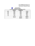
I LIMITED WARRANTY ON MOTOR
Model Series 5000: The motor is warranteed to be free from any defect
in materials and/or workmanship for a period of 60 full months (5 years)
from date of purchase.
Model Series 4000 and 700WHC: The motor is warranteed to be free
from any defect in materials and/or workmanship for a period of 48 full
months (4 years) from the date of purchase.
Model Series 1000: The motor is warranteed to be Free from any defect
Model Series 2000: The motor is warranteed to be free from any defect
in materials and/or workmanship for a period of 12 full months (1 year)
in materials and/or workmanship for a period of 24 full months (2 years)
from the date of purchase.
from the date of purchase.
This warranty does not cover non-defect damage, damage caused by unreasonable use (including abuse, failure to provide reasonable and necessary
maintenance, or any alterations to the product), labor charges for dismantling or re-installing of a repaired or replaced unit or replacement batteries.
If, during the warranty period. the product appears as though it may be defective, CALL OUR TOLL FREE SERVICE NUMBER BEFORE DISMANTLING IT
(1-800-528-9131). II the product is then alleged to be defective. please send it pre-paid and insured to our Service Center to obtain warranty repair. You will
be advised of shipping instructions when you call the number listed above.
Please be sure to include a brief description of the problem and a dated proof-of-purchase receipt with any product that is returned for warranty repair.
Product under warranty, which upon receipt by Chamberlain is determined to be defective in materials and/or workmanship, will be repaired or replaced
(Chamberlain's option) at no cost to you and returned pre-paid. Defective parts will be repaired or replaced with new or factory rebuilt parts at
Chamberlain's option.
THE DURATION OF IMPLIED WARRANTIES OF MERCHANTABILITY AND FITNESS FOR A PARTICULAR PURPOSE IS LIMITED TO THE DURATION
OF THIS WRITTEN WARRANTY. SOME STATES MAY NOT ALLOW LIMITATIONS ON HOW LONG AN IMPLIED WARRANTY LASTS, SO THE ABOVE
LIMITATION MAY NOT APPLY TO YOU.
All claims for consequential or incidental damages for breach of this warranty are excluded and in no event shall manufacturer's liability for breach of
warranty, negligence, strict liability or breach of contract exceed the cost of the product covered herein, but the purchaser is entitled to the remedies
expressly provided in this policy. Some states do not allow the exclusion or limitation incidental or consequential damages, so the above limitation or
exclusion may not apply to you.
No representative or person is authorized to assume for us any other liability in connection with the sale of this product. This warranty gives you specific
Legal rights, and you may also have other rights which may vary from state to state.
114A1301D
1991, The Chamberlain Group, Inc.
All rights reserved
Printed in Mexico