1
Carson Manufacturing Co., Inc.
5451 North Rural Street
Indianapolis, IN 46220
Phone: (888) 577-6877 Fax: (317) 254-2667
www.carsonsirens.com
TECHNICAL BULLETIN
OFF/ON
RADIO
SIREN
HRN/TT
PA
VOL
MAN
WAIL
ON
YELP
PHASR/W-Y
POWER
SA 441
INSTALLATION AND
OPERATING MANUAL
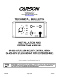
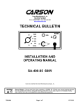
SA-441-83F (FLUSH MOUNT CONTROL HEAD)
SA-441-83FX (FLUSH MOUNT WITH EXTENDED MIC)
Carson is a trademark of Carson Manufacturing Company, Inc.
Sound Hazard - Sound level from siren speaker (>120dBA @ 10 feet) may cause hearing damage.
Do not operate siren without adequate hearing protection for you and anyone in immediate vicinity.
(Ref. OSHA 1910.95 for occupational noise exposure guidelines)
TB0335B
Page 1 of 10
10/18/03
SA-441-83
INPUT POWER:
SIREN MODE
OUTPUT POWER:
AUDIO MODE
OUTPUT POWER:
SIREN
FREQUENCY:
CYCLE RATES:
AUDIO
RESPONSE:
SPECIFICATIONS
11-16 Volts DC, 8 Amps DC per 100W Speaker
Power off current to amplifier is 1mA Max.
15 VDC input, 100W speakers
Two outputs - 105 Watts RMS per output
14 VDC input, 100W speakers
Two outputs - 40 Watts RMS per output
700Hz - 1450Hz Nominal
WAIL - 15 cycles/min
YELP - 210 cycles/min
PHASER - 10 cycle/sec
200Hz - 10KHz +/-3db
Harmonic Distortion Less than 3% @ 1KHz
RADIO INPUT
SENSITIVITY:
0.75VAC Input Min. for 40 Watts RMS Output (1 spkr)
OPERATING
TEMPERATURE:
-15° F to +140° F
SIZE:
Amplifier
Control Head
9" Wide X 2-1/2" High X 6-3/4" Deep
6-1/4" Wide X 2-7/8" High X 1" Deep
WEIGHT:
Amplifier
Control Head
4.25 pounds
1 pound
NIGHT VISIBILITY:
Control Head panel is backlit with independent lead tied to vehicle dash lights.
AMPLIFIER PROTECTION:
High Voltage – Siren output stops with input voltage above highest rating
Stops high output power from blowing speaker
Reverse Polarity – Fuse(s) blows when power is wired backwards
Shorted Output – Fuse(s) blows if speaker shorts (a common problem)
CONTROL HEAD PROTECTION:
No fuse but has reverse polarity protection.
NOTICE
Due to continuous product improvements, we must reserve the right to change any specifications and information,
contained in this manual at any time without notice.
Carson Manufacturing Co., Inc. makes no warranty of any kind with regard to this manual, including, but not limited to,
the implied warranties of merchantability and fitness for a particular purpose.
Carson Manufacturing Co., Inc. shall not be liable for errors contained herein or for incidental or consequential
damages in connection with the furnishing, performance, or use of this manual.
TB0335B
Page 2 of 10
10/18/03
INSTALLATION
Proper installation of the unit is essential for years of safe, reliable operation. Please read all instruction before
installing the unit. Failure to follow these instructions can cause serious damage to the unit or vehicle and may void
warranties.
SAFETY PRECAUTIONS
For the safety of the installer, vehicle operator, passengers and the community please observe the following safety
precautions. Failure to follow all safety precautions and instructions may result in property damage, injury or
death.
Qualifications - The installer must have a firm knowledge of basic electricity, vehicle electrical systems and
emergency equipment.
Sound Hazard - Sound level from siren speaker (>120dBA @ 10 feet) may cause hearing damage.
Do not operate siren without adequate hearing protection for you and anyone in immediate vicinity.
(Ref. OSHA 1910.95 for occupational noise exposure guidelines)
Mounting - Mount the control head for easy access by the vehicle operator. DO NOT mount in air bag deployment
area. Assure clearances before drilling in vehicle.
Wiring - Use wiring capable of handling the current required. Make sure all connections are tight. Route wiring to
prevent wear, overheating and interference with air bag deployment. Install and check all wiring before connection to
vehicle battery.
Testing - Test all siren functions after installation to assure proper operation. Test vehicle operation to assure no
damage to vehicle.
Keep These Instructions - Keep these instructions in the vehicle or other safe place for future reference. Advise the
vehicle operator of the location.
AMPLIFIER MOUNTING
Choose a mounting location in an area such as the driver compartment firewall, under a seat, etc. Mounting the
amplifier in the engine compartment or in an area directly exposed to weather is not recommended. Assure adequate
ventilation to prevent overheating. Consider wire routing and access to connector. Install amplifier to vehicle using
1/4" hardware (not supplied).
May need to set RADIO VOLUME ADJUST on side of amplifier before final mounting and installation.
May also need to set POWER OUTPUT ADJUSTMENT on inside of amplifier.
CONTROL HEAD MOUNTING
Select a mounting location in an area such as the dash or overhead console. Choose a mounting location convenient
to the operator and away from any air bag deployment areas. Consider wire routing and access to connections, as
well as microphone bracket placement.
A microphone clip along with mounting screws (CP3633) holds the microphone in place.
FLUSH MOUNT
The flush mount control head requires a hole in the dash. Use the mounting template on the last page. Note that the
template may not print actual size and may need sizing on a copier. Use #6 screws to fasten to dash.
FLUSH MOUNT WITH EXTENDED MICROPHONE
The flush mount control head with extended microphone is mounted the same as the flush mount except that the
microphone cable extension will also go behind the dash. Allow room for this cable as well.
Control Head – Rear View
Microphone
Extension
Cable
TB0335B
Page 3 of 10
10/18/03
CONTROL HEAD ELECTRICAL CONNECTIONS
All control head leads may be extended with #22 AWG or larger lead wire.
Negative Connection (Black) - Connect to same ground or negative supply as amplifier.
Positive Connection (Red) - Connect to positive DC supply. It is recommended that the lead be connected to the
accessory output of the fuse block. This provides additional protection of a fused input to the control head.
Lights (Yellow) - This lead may be connected to the dash lights or to the red power lead. Connecting to the dash
lights will turn on the panel lights whenever the dash lights are on.
When connected to the red lead, make sure that the ignition switch controls the power to that connection. This
prevents the panel lights from being continuously on.
Control (White) - Connect to white lead from amplifier. Route this lead away from radio transmitter antenna lead to
prevent RF interference being fed to the siren amplifier.
Auxiliary Input (Green) - Used for Siren control. Performs same function as Siren button. Connect to a normally
open switch or to horn ring circuit. Circuit may connect to either positive or negative. When connected to horn ring
circuit, use a SPDT switch to connect horn ring to either vehicle horn or to manual control circuit.
NOTE: Permanent disconnection of the vehicle horn is NOT recommended.
NOTE: Be sure to cut lead short if not used to prevent R.F. interference and insulate with electrical tape.
Added
SPDT
Switch
HORN
RING
SWITCH
HORN
AUX
HORN RING
CONNECTION
TB0335B
Page 4 of 10
10/18/03
AMPLIFIER ELECTRICAL CONNECTIONS
Disconnect vehicle battery before making the following electrical connections.
Electrical connections to the amplifier are made using the wiring harness supplied. If the amplifier needs service the
connector can be easily removed without unwiring the harness. The power supply for the amplifier must be capable of
delivering peak currents up to 50 amps for adequate short circuit protection and reliable operation. The preferred
source is directly at the vehicle battery. A fuse on the unit protects from overload.
Wire Size and Termination - The diagram shows the minimum wire size used for each connection. If the wire is
longer than 10 ft. use the next larger wire size. Use only high quality crimp connectors for installation on the vehicle.
Negative Connection (Black) - Both leads must be used. Connect to negative battery connector or high current
buss.
Positive Connection (Red) - Both leads must be used. Connect to positive battery connector or high current buss. A
power relay may be used.
Speaker A Connection (Brown) - Both leads must be used. Connect 1 lead to each terminal or lead of the speaker.
Connect in same polarity (phasing) as Speaker B to assure loudest siren sound.
Speaker B Connection (Orange) - Both leads must be used. Connect 1 lead to each terminal or lead of the speaker.
Connect in same polarity (phasing) as Speaker A to assure loudest siren sound.
Control Connection (White) - Connect to white lead from control head. Route this lead away from radio transmitter
antenna lead to prevent RF interference being fed to the siren amplifier.
Optional Radio Input Connection (Blue) - Connect 1 lead to each terminal of the radio speaker or output connector.
The input is isolated and polarity is not important. May need to set RADIO VOLUME ADJUST on side of unit.
CONTROL HEAD
OFF/ON
GRN (AUX)
RADIO
PA
SIREN VOL
HRN/TT
MAN
#14 AWG BLK
Use both leads
Extend with #12
WAIL
YELP
PHASR/W-Y
POWER
RED (+VDC)
-
WHT
CONTROL
+
#14 AWG RED
Use both leads
Extend with #12
SPKR
A
-
AMPLIFIER
RADIO VOLUME
ADJUST
#18 AWG BRN
SPKR
B
#18 AWG ORG/BLK
BLU TO TWO WAY
RADIO SPEAKER
FUSE A (SPKR A)
#18 AWG ORG
-
(CP3889
CABLE)
15AMP FUSE
AUTOMOTIVE TYPE
#18 AWG BRN/BLK
Extend spkr leads with #16
+
YEL (DASH LIGHTS)
BLK (-VDC)
ON
BAT
+
(CP3040 CABLE)
FUSE B (SPKR B)
CP3877
CABLE
(CP3877 CABLE)
For loudest siren sound
be sure speakers are wired
in same polarity.
AMPLIFIER POWER
HARNESS CONNECTIONS
TB0335B
- ORG/BLK TO SPKR B + ORG TO SPKR B +
BLK TO -VDC
RED TO +VDC
Page 5 of 10
- BRN/BLK TO SPKR A + BRN TO SPKR A +
10/18/03
NORMAL OPERATION (Dual Mode Switch Off)
Sound Hazard - Sound level from siren speaker (>120dBA @ 10 feet) may cause hearing damage.
Do not operate siren without adequate hearing protection for you and anyone in immediate vicinity.
(Ref. OSHA 1910.95 for occupational noise exposure guidelines)
DUAL MODE
SWITCH
OFF/ON
RADIO
SIREN
HRN/TT
PA
VOL
MAN
WAIL
ON
YELP
PHASR/W-Y
POWER
SA 441
The Toggle Power Switch controls the siren power. The siren may be left on any time the vehicle is in
operation. The power should be turned off when vehicle is not being used to conserve battery power.
The Rotary Function Switch selects various operating modes. These modes are as follows:
RADIO -
This mode reproduces, or repeats, the output of a radio. The radio must be connected and
RADIO VOLUME ADJUSTed for this mode to function. PA override available in this mode.
HORN -
Also considered a standby mode. Horn and PA Override available in this mode.
MAN -
The siren tone is controlled Manually with SIREN button. PA Override available in this mode.
WAIL -
The siren produces a normal rise-fall tone pattern. This mode should be used on highways or
areas with constant traffic flow. Yelp and PA Override available in this mode.
YELP -
The siren produces a moderate warble tone. This mode should be used in lightly congested
areas. Horn and PA Override available in this mode.
PHASER -
The siren produces a very fast warble tone. This mode should be used at intersections or in
highly congested areas. Horn and PA Override available in this mode.
OVERRIDE FUNCTIONS (Normal Mode)
PUBLIC ADDRESS
(PA) OVERRIDE -
Pressing the microphone button in any operating mode allows the operator to use the siren as
a public address amplifier. The operating mode resumes when the button is released. (Hold
the microphone close to your lips for proper operation and adjust the PA VOLume Control)
HORN OVERRIDE -
By pressing the SIREN button the siren tone output is replaced by the horn tone. The siren
tone resumes when the button is released. (This feature is not available in WAIL mode.)
YELP OVERRIDE -
Available only in WAIL mode. By momentarily pressing the SIREN button the tone output is
switched to the Yelp tone. Pressing the button again switches the tone output back to Wail.
RADIO VOLUME ADJUST
The RADIO VOLUME ADJUST is a one time setting which depends on the radio connected and its normal volume.
Access the RADIO VOLUME ADJUST through a hole on the side of the amplifier.
Switch siren to RADIO mode and turn on the power. With the volume on the radio itself set to normal level, set the
RADIO VOLUME ADJUST to the desired level.
TB0335B
Page 6 of 10
10/18/03
DUAL MODE OPERATION (Dual Mode Switch On)
Sound Hazard - Sound level from siren speaker (>120dBA @ 10 feet) may cause hearing damage.
Do not operate siren without adequate hearing protection for you and anyone in immediate vicinity.
(Ref. OSHA 1910.95 for occupational noise exposure guidelines)
The Toggle Dual Mode Switch gives the amplifier the ability to produce two different siren tones to each
speaker simultaneously. This changes some of the Rotary Function Switch modes and provides different Override
Functions. The Dual Mode Switch may be left on and use the Rotary Manual position as standby mode.
The Rotary Function Switch selects the following modes:
RADIO -
Same as normal mode. PA override available in this mode.
TWO-TONE -
Or HI-LO, a common European tone. Both speakers produce same sound. Horn and PA
Override available in this mode.
MAN -
In dual mode this is also considered standby mode. The siren tone is controlled manually with
SIREN button. Both speakers produce manual tone slightly out of phase to give stereo effect.
PA Override available in this mode.
WAIL -
The siren produces dual Wail. Each speaker produces independent Wail tone. Dual Yelp and
PA Override available in this mode.
YELP -
The siren produces dual Yelp. Each speaker produces independent Yelp tone. Phaser and
PA Override available in this mode.
WAIL/YELP -
The siren produces Wail to one speaker and Yelp to the other speaker. Phaser and PA
Override available in this mode.
OVERRIDE FUNCTIONS (Dual Mode)
PUBLIC ADDRESS
(PA) OVERRIDE -
Same as normal mode.
HORN OVERRIDE -
Same as normal mode, both speakers produce same Horn tone.
DUAL YELP
OVERRIDE -
Available only in Dual Wail mode. By momentarily pressing the SIREN button the tone output
is switched to the Dual Yelp tone. Pressing the button again switches the tone output back to
Dual Wail.
PHASER OVERRIDE - By pressing the SIREN button the siren tone output is replaced by the Phaser tone. Both
speakers produce same Phaser tone. The siren tone resumes when the button is released.
TB0335B
Page 7 of 10
10/18/03
SERVICE
This unit is designed to provide years of reliable service under even the worst conditions. Many times there may
appear to be a problem with the unit when the true problem is in the speaker(s) or improper installation. The following
chart shows typical symptoms and possible causes.
A blown panel fuse(s) doesn't necessarily mean that the unit is bad. If a speaker or speaker lead is shorted this fuse
will blow before the unit is damaged. Disconnect the SPKR leads and replace the fuse. If the siren emits a sound
when in the Yelp position it is OK. Check the speaker(s) or leads for possible shorting.
Note: Older versions of this amplifier unit used one 20AMP fuse to supply both internal amplifiers. This means that if
one internal amplifier output is shorted and blows the fuse, the other internal amplifier will also lose power even though
it may be fine. Be sure to check both amplifier unit outputs for shorted wiring or speaker.
PROBLEMS
Symptom
No Power or siren output
Possible Cause
Power switch not turned on
Bad Speaker
Connector or connections loose
Panel fuse(s) blown
Loose connection at power source
No siren tone –
PA works
No PA
Distorted siren sound
High Voltage Protection
Mic Button stuck
PA volume not set properly
Speaker assembly loose
Intermittent Aux Input connection
Low Vehicle voltage
High Voltage Protection
Connector loose
Loose connection at power source
Mic Button activation
Circuit breaker in supply
connection
Siren switch stuck
Aux Input improperly connected
Intermittent siren tone
Horn or manual stuck on
No Radio
Unit not connected to a radio
Radio volume too low
Wrong siren tone
Ground system noise
Dual mode switch does
not work
Only one internal amplifier works
One speaker damaged
Check
Does backlighting come on?
Do you hear a “pop” when turned on?
With siren on, yelp selected, listen for tone in
amplifier.
Is an external fuse or circuit breaker used?
Are the power leads connected to a good buss?
The input voltage must be less than highest rating.
Does Mic Button release properly?
Try turning the PA volume control.
Is the speaker bell or tip loose?
Is the Aux Input used and wired properly?
The input voltage must be greater than lowest rating.
Is the vehicle voltage regulator working properly?
Is the connector tight on the back of the unit?
Check for loose leads back to power source.
Is something lying on the microphone?
Is a circuit breaker used with at least 50A rating?
Does the Siren pushbutton switch return fully when
released?
Is the Aux Input used and wired properly?
Is the radio connected properly to the unit?
Can you hear the radio in the vehicle?
Try adjusting the internal radio volume control.
Are control head and amplifier connected to good
ground?
Is one fuse on the amplifier blown?
Try replacing the speaker.
RETURN
If you have any questions concerning this or any other Carson product, please contact our Technical Service
Department at (888) 577-6877. Many issues can be handled over the phone. We can also be reached via e-mail at
[email protected]
If a product must be returned for any reason, please contact our Technical Service Department to obtain a Returned
Merchandise Authorization number (RMA#) before you ship the product to Carson. Please write the RMA# clearly on
the package near the mailing label. Be sure to provide a return address, contact and phone number, along with a brief
description of the problem.
TB0335B
Page 8 of 10
10/18/03
PARTS
10
6
1
7
5
2
4
RADIO
OFF/ON
SIREN
HRN/TT
PA
VOL
8
MAN
WAIL
3
9
ON
YELP
PHASR/W-Y
POWER
SA 441
12
11
13
(one pair each end)
(output for
speaker B shown)
Control Head
Item
1
2
3
4
5
6
7
8
9
10
Part #
8025 DRS/CAP
CP3040
ES00003-09
CP3046
CP4000
CP3880
CP4852
CP4853
CP3881
JKL#7001PSBL
CP3570
ES00028-10
CP3633
CP3035-1
8121D2V40
7101-T-C-Q
CP3599
SS2846
Description
Button, red w/ dress nut (C&K #801803000 Cap, #702501201 Nut) (for pushbutton switch)
Cable, control head power
Cable, microphone extension 8FT (CP3850 is 18FT) (for SA-441-83FX version)
Control, PA volume (1K ohm) (for all other PCB's)
Control, PA volume no face mount (1K ohm) (for PCB CP3873 Rev. E and higher)
Cover, control head back push on
Knob, rotary function switch
Knob, PA volume control
Label, control head front panel
Lamp, T-1-3/4 14V Bi-pin (JKL #7001)
Microphone (for SA-441-83F version)
Microphone with locking connector (for SA-441-83FX version)
Microphone clip with mounting screws
Panel, control head front
Switch, pushbutton siren (C&K #8121SD2V4GE)
Switch, toggle power (C&K #7101TCQ)
Switch, rotary function
Switch, toggle dual mode (C&K #7101MYW3BE)
Amplifier
Item
11
12
13
Part #
CP3877
CP3889
640584-1
CP3876
CP3408
CP4119
TB0335B
Description
Cable, amplifier power
Cable, radio and control line
Connector, power (AMP #640584-1)
Cover, amplifier (does not include CP3875 chassis)
Fuse holder
Transistor, output (pairs required) (Industry standard TIP36C, Not Texas Instruments)
Page 9 of 10
10/18/03
TB0335B
Page 10 of 10
2-7/8”
2-1/2”
CAUTION: Please note that top and bottom edges only
provide 1/8” overlap. Cut carefully.
This inner area
to be removed.
5-1/4”
5-7/8”
6-1/4”
1/8”
2-5/8”
1/2”
CONTROL HEAD INSTALLATION TEMPLATE
10/18/03