1
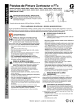
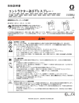
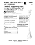
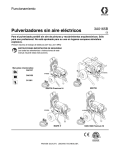
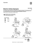
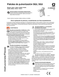
Instructions-Parts
Contractor & FTx Spray Guns
Contractor Models: 288420, 288421, 288425, 288475, 288477, 288478, 826085, 288009
FTx Models: 288427, 288428, 288429, 288430, 288431, 288436, 288438, 288477,
288478, 826086, 288008,262114, 262116
311861G
For the application of architectural paints and coatings.
Maximum Working Pressure: 3600 psi (248 bar, 24.8 MPa)
IMPORTANT SAFETY INSTRUCTIONS. Read all
warnings and instructions in this manual. Refer to your
sprayer instruction manual for Pressure Relief, priming and
spray instructions. Save all instructions.
ti8501b
ti8522b
The following warnings are for the setup, use, grounding, maintenance, and repair of this equipment. The exclamation point symbol
alerts you to a general warning and the hazard symbol refers to procedure-specific risk. Refer back to these warnings. Additional,
product-specific warnings may be found throughout the body of this manual where applicable.
WARNING
SKIN INJECTION HAZARD
High-pressure fluid from gun, hose leaks, or ruptured components will pierce skin. This may look like just a cut, but it
is a serious injury that can result in amputation. Get immediate surgical treatment.
•
Do not point gun at anyone or at any part of the body.
•
Do not put your hand over the spray tip.
•
Do not stop or deflect leaks with your hand, body, glove, or rag.
•
Do not spray without tip guard and trigger guard installed.
•
Engage trigger lock when not spraying.
•
Follow Pressure Relief Procedure in this manual, when you stop spraying and before cleaning, checking, or
servicing equipment.
FIRE AND EXPLOSION HAZARD
Flammable fumes, such as solvent and paint fumes, in work area can ignite or explode. To help prevent fire and
explosion:
•
Use equipment only in well ventilated area.
•
Eliminate all ignition sources; such as pilot lights, cigarettes, portable electric lamps, and plastic drop cloths
(potential static arc).
•
Keep work area free of debris, including solvent, rags and gasoline.
•
Do not plug or unplug power cords, or turn power or light switches on or off when flammable fumes are present.
•
Ground all equipment in the work area. See Grounding instructions.
•
Use only grounded hoses.
•
Hold gun firmly to side of grounded pail when triggering into pail.
•
If there is static sparking or you feel a shock, stop operation immediately. Do not use equipment until you identify and correct the problem.
•
Keep a working fire extinguisher in the work area.
PRESSURIZED ALUMINUM PARTS HAZARD
Use of fluids that are incompatible with aluminum in pressurized equipment can cause a serious chemical reation and
equipment rupture. Failure to follow this warning may result in death, serious injury, or property damage.
• Do not use 1,1,1-trichloroethane, methylene chloride, other halogenated hydrocarbon solvents or fluids containing such solvents.
• Many other fluids may contain materials that are incompatible with aluminum. Contact your material supplier for
verification.
II 2 G
WARNING
EQUIPMENT MISUSE HAZARD
Misuse can cause death or serious injury.
• Do not operate the unit when fatigued or under the influence of drugs or alcohol.
• Do not exceed the maximum working pressure or temperature rating of the lowest rated system component. See
Technical Data in all equipment manuals.
• Use fluids and solvents that are compatible with equipment wetted parts. See Technical Data in all equipment
manuals. Read fluid and solvent manufacturer’s warnings. For complete information about your material,
request MSDS forms from distributor or retailer.
• Check equipment daily. Repair or replace worn or damaged parts immediately with genuine manufacturer’s
replacement parts only.
• Do not alter or modify equipment.
• Use equipment only for its intended purpose. Call your distributor for information.
• Route hoses and cables away from traffic areas, sharp edges, moving parts, and hot surfaces.
• Do not kink or over bend hoses or use hoses to pull equipment.
• Keep children and animals away from work area.
• Comply with all applicable safety regulations.
PERSONAL PROTECTIVE EQUIPMENT
You must wear appropriate protective equipment when operating, servicing, or in the operating area of the equipment to help protect you from serious injury. This equipment includes but is not limited to:
• Protective eyewear, gloves, hearing protection
• Clothing and respirator as recommended by the fluid and solvent manufacturer
Pressure Relief Procedure
Setup
Make sure sprayer is turned off and unplugged
from power source. Refer to your sprayer
manual for priming and spray instructions.
Follow this Pressure Relief Procedure whenever instructed
to relieve pressure, stop spraying, check or service equipment,
or install or clean spray tip.
1.
2.
Turn OFF power and turn sprayer pressure control to lowest pressure setting.
Hold gun against side of flushing pail. Trigger gun into pail
to relieve pressure.
If you suspect spray tip or hose is clogged or that pressure has
not been fully relieved after following the steps above, VERY
SLOWLY loosen tip guard retaining nut or hose end coupling
to relieve pressure gradually, then loosen completely. Clear
hose or tip obstruction.
Gun Trigger Lock (2)
To prevent injury when the gun is not in use,
always set the gun’s trigger lock (2) if unit is
being shut down or left unattended.
Trigger Locked
(no spray)
Trigger
Unlocked
(spray)
Connect Gun to Sprayer
1.
2.
3.
Attach supply hose to sprayer fluid outlet.
Attach other end of supply hose to gun swivel (8). Use two
wrenches (one on the swivel (8) and one on the hose), to
tighten all connections securely.
Refer to sprayer instruction manual for priming
instructions.
Installing Tip (26) and Guard (25) on Gun
1.
2.
3.
4.
If equipment has recently been operated, relieve pressure. Set trigger lock (2).
Using a pencil or similar object, insert seal (24) into back
of guard (25).
Install guard (25) over end of gun (1).
Insert tip (26) in guard (25). Tighten retaining nut.
Operation
Spraying
ti10166a
ti10167a
1.
2.
3.
4.
2
Unlock trigger lock (2).
Be sure the arrow shaped tip (26) faces forward (spray).
Hold gun perpendicular and approximately 12-inches
(304 mm) from surface. Move gun first, then pull gun
trigger (13) to spray a test pattern.
Slowly increase pump pressure until coverage is uniform
and even (see sprayer instruction manual for additional
information).
311861G
Aligning Spray
Clearing Clogs
1.
1.
2.
Relieve pressure. Set trigger lock (2). Loosen guard
retaining nut.
Loosen guard retaining nut.
Align guard (25) horizontally to spray a horizontal pattern.
Align guard (25) vertically to spray a vertical pattern.
2.
3.
4.
(3) Horizontal
(4) Vertical
3.
Parts
Relieve pressure. Set trigger lock (2).
Rotate tip (26) 180°. Unlock trigger lock (2). Trigger gun
into pail or onto ground to remove clog.
Set trigger lock (2). Rotate tip (26) 180° back to spray
position.
Cleanup
Flush gun after each work shift and store in a dry location. Do
not leave the gun or any parts in water or cleaning solvents.
ti9535B
ti9534B
Parts
1
20
14
Ref.
1
22
21
5
15a
15b
16/17
(see page 4)
6
5
2
13
11
7b
19
12
6
7
7a
7b
8
9
10
11
12
13
7a
Part
288812
289914
287032
287033
287034
120777
15K282
15J735
15J736
288811
120733
15J706
15J698
120834
15J409
15J768
15J769
9
31
10
ti8502b
8
14
15
15a
15b
16
17
19
20
21
22
31
117602
288488
15J696
105334
15J464
15J528
121093
15B549
119799
Description
HOUSING, assy., Contractor
HOUSING, assy., FTX
FILTER, 60 mesh
FILTER, 100 mesh
FILTER, 60 and 100 mesh combo
PACKING, o-ring
HANDLE
Contractor Gun
FTX Gun
FTX-A Gun (not shown)
SWIVEL, assy, gun
O-RING, urethane, clear
RETAINER, guard, trigger
TUBE, handle, Contractor Gun
SCREW, set, Contractor Gun
TRIGGER, Contractor Gun
TRIGGER, Contractor Gun, 4-finger
(not shown)
TRIGGER, FTX Gun, 4-finger (not
shown)
SCREW, shoulder, pan hd
KIT, needle, repair
NEEDLE, assembly
DIFFUSER, assembly
PIN, trigger (page 4)
NUT, lock, hex (page 4)
GUARD, trigger
GUIDE, spring
SPRING, compression
NUT, end
BRUSH, cleaning
Qty
1
1
1
1
1
1
1
1
1
1
1
1
1
1
1
1
1
Description
Qty
1
1
1
1
1
1
1
1
1
1
1
1
2
1
1
1
1
1
1
1
1
1
1
Tip and Guard
RAC X
24
24
RAC 5
Ref.
24
25
26
25
311861G
26
25
ti8505a
26
_
Part
246453
243281
246215
243161
LTX515
LTX517
286515
286517
PAA517
PAA515
262517
™,
OneSeal RAC X (5-pack)
OneSeal™, RAC 5 (5-pack)
GUARD, RAC X
GUARD, RAC 5
TIP, spray 515, RAC X
TIP, spray 517, RAC X
TIP, spray 515, RAC 5
TIP, 517, RAC 5
TIP, spray, latex, RAC X (517), Europe
TIP, spray, latex, RAC X (515), Europe
TIP, spray. 517, RAC 5, Europe
3
Maintenance
Failure to clean or replace the
filter or damaged handle bore
can result in serious injury.
Before performing any maintenance on gun, read all warnings
on front cover of this manual and relieve pressure.
Cleaning/Replacing Filter (5)
A plugged filter reduces gun performance. Clean filter after
each use.
1.
2.
3.
4.
5.
6.
Relieve pressure. Set trigger lock (2).
Disconnect fluid hose from gun at swivel (8).
Disconnect trigger guard (19) from guard retainer (10).
Unscrew handle (7) from gun (1).
Remove filter (5) through top of handle (7).
Inspect filter (5) for damage to the filter mesh. Replace the
filter if the filter mesh has holes or voids.
7. Clean filter (5). Use a soft brush to loosen and remove
excess debris.
8. Inspect handle bore (7) for damage. Replace the handle
bore if it is corroded or pitted and check material for
compatibility with aluminum.
9. Insert clean filter (5) into handle (7).
10. Reattach handle (7) to gun (1). Tighten securely.
11. Reconnect trigger guard (19) to guard retainer (10).
Repair
Tools needed:
• 8-inch adjustable wrench
• 1/4-inch nut driver
Replacing Needle
15a
17
15b
16
a
1.
2.
3.
4.
5.
6.
7.
8.
9.
Relieve pressure. Set trigger lock (2).
Remove tip (26) and guard (25) from gun (1).
Disconnect fluid hose from gun at swivel (8).
Remove nut (17) and trigger pin (16).
Unscrew diffuser (15a) from front of gun (1).
Remove needle assembly (15b) through front of gun (1).
Use a soft brush to clean out internal passages of gun.
Grease o-rings of new needle using a non-silicon grease.
Guide new needle (15b) through front of gun (1) making
sure the flat sides (a) of the needle assembly face the
sides of gun housing.
10. Install diffuser (15a). Torque diffuser to 26-30 ft-lbs
(35.25 - 43.38 N•m).
11. Replace pin (16) and nut (17).
Translated Manuals
Spanish - 312098
Estonian - 312277
French - 312099
Latvian - 312278
Dutch - 312265
Lithuanian - 312279
German - 312266
Polish - 312280
Italian - 312267
Hungarian - 312281
Turkish - 312268
Czech - 312282
Greek - 312269
Slovakian - 312283
Croatian - 312270
Slovenian - 312284
Portuguese - 312271
Romanian - 312285
Danish - 312272
Bulgarian - 312286
Finnish - 312273
Chinese - 312287
Swedish - 312274
Japanese - 312288
Norwegian - 312275
Korean - 312289
Russian - 312276
1
Translated manuals can be requested through a distributor or
at www.graco.com.
ti8510b
Technical Data
Maximum working pressure
3600 psi (248 bar, 24.8 MPa)
Fluid orifice size
0.125 in. (3.18 mm)
Weight (with tip and guard)
22 oz. (630 g)
Inlet
1/4 npsm swivel
Maximum material temperature
120°F (49°C)
Wetted parts
Stainless steel, polyurethane, nylon, aluminum, tungsten carbide, solvent resistant elastomer, brass
Noise Level*
Sound power
87 dBa
Sound pressure
78 dBa
*Measured at 3.1 feet (1m) while spraying water-based paint, specific gravity 1.36, through a 517 tip at 3000 psi (207 bar, 20.7 MPa) per ISO 3744
For complete warranty information contact your Graco distributor, call Graco customer service: 1-800-690-2894 or visit our website: www.graco.com
All written and visual data contained in this document reflects the latest product information available at the time of publication.
Graco reserves the right to make changes at any time without notice.
This manual contains English. MM 311861
Graco Headquarters: Minneapolis
International Offices: Belgium, China, Japan, Korea
GRACO INC. P.O. BOX 1441 MINNEAPOLIS, MN 55440-1441
Copyright 2007, Graco Inc. is registered to ISO 9001
www.graco.com
Revised 03/2009