1
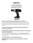
CME35
201201
4 Cu Ft. Cement Mixer
Assembly & Operating Instructions
READ ALL INSTRUCTIONS AND WARNINGS BEFORE USING THIS PRODUCT.
This manual provides important information on proper operation & maintenance. Every effort has been
made to ensure the accuracy of this manual. These instructions are not meant to cover every possible
condition and situation that may occur. We reserve the right to change this product at any time
without prior notice.
IF THERE IS ANY QUESTION ABOUT A CONDITION BEING SAFE OR UNSAFE, DO
NOT OPERATE THIS PRODUCT!
HAVE QUESTIONS OR PROBLEMS? DO NOT RETURN THIS PRODUCT TO THE
RETAILER - CONTACT CUSTOMER SERVICE.
If you experience a problem or need parts for this product, visit our website http://www.buffalotools.com
or call our customer help line at 1-888-287-6981, Monday-Friday, 8 AM - 4 PM Central Time. A copy of
the sales receipt is required.
FOR CONSUMER USE ONLY – NOT FOR PROFESSIONAL USE.
KEEP THIS MANUAL, SALES RECEIPT & APPLICABLE WARRANTY FOR FUTURE
REFERENCE.
Mixer Paddles
GENERAL PRODUCT SPECIFICATIONS
Drum
Motor Cover
SPECIFICATIONS
180 lb Dry Mix Capacity
Plugs Into 110 Volt Outlet
2/3 HP
Support
Arm
15” Diameter Drum Opening
Drum Tips 360 Degrees
Adjusting
Plate
Power Switch
FEATURES:
Double Insulated
Handles Two 90-lb. Bags Of
Dry Cement Or Mortar Mix
Also Mix Feeds, Fertilizers
& Potting Soil
Support
Leg
Wheel
Wheel
SAVE THESE INSTRUCTIONS FOR FUTURE REFERENCE.
This manual contains important information regarding safety, operation, maintenance and storage of this
product. Before use, read carefully and understand all warnings, cautions, instructions and labels.
Failure to do so could result in serious personal injury, property damage or even death.
IMPORTANT SAFETY RULES
COMMON SENSE AND CAUTION ARE FACTORS WHICH CANNOT BE BUILT INTO ANY PRODUCT.
THESE FACTORS MUST BE SUPPLIED BY THE OPERATOR.
Keep your work area clean and well lit. Cluttered work benches and dark work areas may cause
accidents or injury.
Keep bystanders, children and visitors away while operating the Cement Mixer. Distractions can
cause you to lose control.
Do not force tool. Use the correct tool for your application. The correct tool will do the job better and
safer at the rate for which it is designed.
Store idle tools out of reach of children and other untrained persons. Tools are dangerous in the
hands of untrained users.
Use common sense while operating this cement mixer.
Do not use this tool if you are:
• Feeling tired or are under the influence of alcohol or drugs.
• Wearing loose clothing or jewelry. Keep long hair pulled back and away from moving parts.
• Overreaching or have improper footing. Handling the tool in this way could cause serious injury.
• Wear the proper safety equipment, such as safety goggles, dust masks, non-skid shoes, etc.
• Check to be sure all adjusting keys or wrenches have been removed before use.
CME35 4 Cu Ft. Cement Mixer Assembly & Operating Instructions Manual
2
Do not use the cement mixer if the switch does not turn it on and off. Any tool that cannot be
controlled with the switch is dangerous and must be repaired.
AVOID DANGEROUS CONDITIONS
Make sure there is adequate surrounding workspace. Keep your work area clean and well lighted.
Cluttered areas invite injuries. Keep area around the mixer clear of obstructions, grease, oil, trash and
other debris which could cause persons fall onto moving parts. Only use or operate the mixer on solid,
flat, level ground that is capable to support the weight of the mixer and its load to prevent the mixer
from tipping over. Do not attempt to move the mixer when it is loaded and/or in operation. This mixer is
intended for the production of concrete, mortar and plaster. It is not suitable for the mixing of flammable
or explosive substances. Do not use it in areas where fumes from paint, solvents or flammable liquids
pose a potential hazard.
INSPECT YOUR MIXER
Check your mixer before turning it on. Keep guards in place and in working order. Do not plug mixer
with motor cover off. Check all bolts, nuts, and screws for tightness before each use, especially those
securing guards and drive mechanisms. Vibration during mixing may cause these to loosen. Replace
damaged, missing or failed parts before using it.
Do not wear loose clothing, gloves, neckties or jewelry (rings, wrist watches): They can be caught in
moving parts. Protective electrically non-conductive gloves and non-skid footwear are recommended
when working. Wear protective hair covering to contain long hair, preventing it from getting caught in
machinery. Wear a face or dust mask if the operation is dusty. Always wear safety goggles and/or face
shields. Everyday eyeglasses have only impact resistant lenses. They are not safety glasses.
Safety glasses and ear protection must be worn during operation. Wear eye protection (see ANSI
Z49.1 safety standard), non-conductive gloves and non-skid footwear.
DO NOT ABUSE CORD
Never carry mixer by cord or yank it to disconnect from socket. Keep cord from heat, oil & sharp edges.
EXTENSION CORDS
Extension cords must be no longer than 164 feet in length. The wire section must be big enough to
allow sufficient current flow to the motor. Improper use of extension cords may cause inefficient
operation of the mixer which can result in overheating and motor damage. Only extension cords to
H07RN-F specification intended for outdoor purpose may be used. Avoid use of free and inadequately
insulated connections. Connections must be made with protected material suitable for outdoor use.
Make sure that any extension cord connections are dry and safe. Ensure that the extension cord is
carefully laid out avoiding liquids, sharp edges and places where vehicles might run over it. Avoid
allowing the extension cord to be trapped underneath the mixer. Unroll it fully or it will overheat and
could catch fire.
AVOID ELECTRICAL SHOCK
Check that the electric circuit is adequately protected and that it corresponds with the power, voltage
and frequency of the motor. Do not plug or unplug the motor while standing in or around damp or wet
ground. Do not use the mixer in wet or damp areas or expose it to rain. Prevent body contact with
grounded surfaces: pipes, radiators, ranges, and refrigerator enclosures. Make sure your fingers do not
touch the plug's metal prongs when plugging or unplugging the mixer.
DO NOT OVERREACH
Keep proper footing and balance at all times when loading or unloading the mixer. Never stand on
mixer. Serious injury could occur if the mixer is tipped. Do not store anything above or near the mixer
where anyone might stand on the mixer to reach them.
CME35 4 Cu Ft. Cement Mixer Assembly & Operating Instructions Manual
3
AVOID INJURY FROM UNEXPECTED ACCIDENT
Keep hands out of the way of all moving parts. Do not place any part of your body or any tool, like
shovel in the drum during operation. When operating, do not pass hands through the clearance
between frame and support arm or the one between the drum and support arm. Never open the motor
cover before unplugging the mixer. Disconnect from power supply when not in use, before moving,
making adjustments, changing parts, cleaning, or working on the mixer.
DO NOT FORCE TOOL
Always work within the rated capacity. Do not start the motor if the drum is fully loaded. Do not turn
mixer off while full of concrete. Do not use the mixer for a purpose for which it was not intended. The
mixer is not to be towed by any vehicle. NEVER LEAVE MIXER RUNNING UNATTENDED. Do not
leave mixer until it has come to a complete stop. DISCONNECT POWER.
PROTECT THE ENVIRONMENT
Take leftover materials to an authorized collection point or follow the stipulations in the country where
the mixer is used. Do not discharge into drains, soil or water.
STAY ALERT
Do not operate the mixer while under the influence of drugs, alcohol, or any medication that could affect
your ability to use it properly. Do not use this mixer when you are tired or distracted from the job at
hand. Watch what you are doing at all times. Use common sense.
This unit contains chemicals known to the state of California to cause birth defects and, in some
cases, cancer. (California Health & Safety code section 25249.5 et seq.)
SERVICE
Tool service must be performed only by qualified repair personnel. Service or maintenance by unqualified
personnel could result in a risk of injury.
When servicing a tool, use only identical replacement parts and follow instructions in the manual. Use
of unauthorized parts or failure to follow Maintenance Instructions may create a risk of shock or injury.
Lower Drum
PARTS DIAGRAM
Upper Drum
Motor
Cover
Manual
Adjusting Plate
Wheels
Support Braces
Support
Leg
Support
Arm
Hardware
Frame Assembly
CME35 4 Cu Ft. Cement Mixer Assembly & Operating Instructions Manual
Wheel Brace
4
ASSEMBLY WARNING! - IT IS RECOMMENDED THAT TWO PERSONS ASSIST IN ASSEMBLY
Figure A. With a split pin inserted into the inner holes in each stub axle, place a flat washer, then a
wheel followed by another flat washer. Insert another split pin into the axle holes outside each flat
washer. Bend each side of the pins outward so they do not fall out.
Figure B. With the frame lying on its side, attach the support leg as shown. Insert two M8X70 hex bolts
through the holes from one side, then flat washers, lock washers and nuts from the other side. Tighten
down.
Figure C. Turn the frame over and attach the axle bracket with wheels in the same manner.
Figure D. Slide the bearing block on the shaft. Hold it in place with 042 spiral ring. Carefully, and with
two people, set the bottom drum with support arm onto the side supports of the stand as shown, so that
the bearing blocks slot into the channels provided by the side supports. The larger diameter shaft
should be at the leg end of the stand. At each side, line up the holes in the side support with those in
the bearing block and insert a M8X65 hex bolt from one side, then a flat washer, lock washer and nut
from the other side. Tighten with a wrench.
THE MIXING BLADES
Figure E. Mount the mixing blades inside the bottom drum loosely as shown - Two holes are provided
at the base of the drum into which a M8X20 bolt may be inserted from the outside. A leather washer,
flat washer, lock washer and a nut should be threaded on loosely on the inside. The leather washer
should be placed under the blade down against the drum. NOTE: Two arrows are labeled on upper
drum and bottom drum to make their position relation. If you have any difficulty in correctly positioning
the mixing blades, it is helpful if you temporarily mount the upper drum on the top of the bottom drum,
rotating it so that the two arrows line up.
Figure F. Position the upper drum on bottom drum over the rim, making sure the mounting holes align
in both as well as the labeled arrows. Insert a M6X16 cross headed screw into each mounting holes in
the rim. Secure each bolt from below with a flat washer, lock washer and nut. Tighten all bolts.
CME35 4 Cu Ft. Cement Mixer Assembly & Operating Instructions Manual
5
Secure the mixing blades to the upper
drum by inserting two M8X16 cross
headed screws, from the outside through
the holes in the drum. A leather washer
should be positioned inside between the
drum and blade. Secure the mixing blade
on the inside using a flat washer, spring
washer and nut. Finally, ensure top and
bottom mixing blade mountings are tight.
Figure G. Position the adjusting plate and
attach with bolts.
Figure H. Slide the support arm over the
adjusting plate and attach with bolts. Place shaft at the leg end of frame
with the rim facing inwards. Secure with two M8X25 bolts, each with a nut,
lock and flat washers. Insert the spring into the bar pipe. Hold it in place
with a finger and place the bar over the larger diameter shaft so the shaft
retains the spring. Press down on bar until the holes in the bracket line up
with the hole drilled. Insert a hex bolt and screw on a nut with flat and
lock washers from the other side. Screw the nut up against the bracket firmly,
but not so tightly so as to prevent the bar from pivoting about the bolt.
Figure I. Line up the motor and slide the transmission case over the
pinion shaft. Secure the case to the frame with four M8 nuts. NOTE:
The bar must be allowed to pivot about the bolt so that the lugs on the
bracket can be engaged or disengaged from the slots in the locking
plate.
LOADING / DRUM TILTING
The spring-loaded tipping bar with locking lugs provides easy control of the drum which can be locked
in the Mix, Discharge and Stored position. The drum is locked in position by lugs on the self-locating
tipping bar, which engages into the locking plate on the mixer frame. To tilt the drum, withdraw the
tipping bar to disengage the locking lugs. This allows the tipping bar and drum to be turned in the same
direction. Rotate the tipping bar until the locking lugs engage into the locking plate on the mixer frame.
NOTE: A built-in thermal protector in the motor will prevent it from overheating. The thermal protector
restores automatically when the motor cools down.
MAINTENANCE
Thoroughly clean the mixer at the end of each day's operation. Keep your mixer clean. The slightest
trace of material left in the drum will harden and attract more each time you use it until the machine is
useless. Dried cement should be scraped out of the drum. Do not throw bricks into mixer drum to clean
it out. Do not beat on the drum to break up accumulations of dried cement mix. The drum may be
scoured for approximately 2 minutes, using 1" gravel and water mixture. Discharge the gravel / water
mixture and hose down the drum assembly inside and out. The drive belt is under constant tension by a
spring-loaded jockey. No adjustment is required apart from a touch of grease on the spindle. The
bearings are sealed for life.
CME35 4 Cu Ft. Cement Mixer Assembly & Operating Instructions Manual
6
PARTS DIAGRAM
PARTS LIST
CME35 4 Cu Ft. Cement Mixer Assembly & Operating Instructions Manual
7
1
2
3
4
5
6
7
8
9
10
11
12
13
15
16
17
18
19
20
21
22
23
24
25
26
27
28
29
30
31
32
33
34
35
36
Cross Headed Screw M6X16
Waterproof Washer
Flat Washer 8
Spring Washer 8
Nut M8
Upper Drum
Cross Headed Screw M6X16
Mixing Blade
Rubber Gasket
Flat Washer 6
Spring Washer 6
Nut M6
Lower Drum
Axle Bracket
Wheel
Flat Washer 27
Cotter pin 5X40
Frame
Support Leg
Bolt M8X70
Bearing Block - Right
Circlip 42
O-ring
Gear Guard - Long
Drive Shaft
Sleeve pipe
Cradle
O-ring 32X2.65
Bearing cover
Bearing 6206
Circlip 30
Circlip 62
Lock Pin 5X45
Sheet Metal Screw ST3.5X16
Drive pinion
4
12
22
22
22
1
6
2
1
6
6
6
1
1
2
4
4
1
1
4
1
1
1
1
1
1
1
1
1
2
1
3
1
3
1
CME35 4 Cu Ft. Cement Mixer Assembly & Operating Instructions Manual
37
38
39
40
41
42
43
44
45
46
47
48
49
50
51
52
53
54
55
56
57
58
59
60
61
62
63
64
65
66
67
68
69
70
71
72
73
Gear Guard - Short
Circlip 42
Bearing 6202
Circlip 15
Locknut M8
Bolt8X65
Circlip 38
Bearing Block - Left
Nut M10
Spring Washer 10
Tipping Bar
Spring
Washer
Bolt M10X60
Tipping Bar
Handle Grip
Bolt M8X25
Locking Plate
Power Cord
Strain Relief Nut
Strain Relief Rubber
Strain Relief Bolt
Strain Relief Nut
Gasket, Switch
Switch
Motor Cover
Motor
Idle Pulley
Belt
Bearing 6906
Snap Washer – Hole 47
Sheet Metal Screw ST4.8X16
Snap Washer – Shaft
End Plate
Bolt M8X30
Motor Mount Bracket, End Plate
Gasket
1
1
2
1
6
2
2
1
1
1
1
1
1
1
1
1
2
1
1
1
1
1
1
1
1
1
1
1
1
2
1
8
1
1
5
1
1
8