1
664B
13 SEER SINGLE--PACKAGED HEAT PUMP SYSTEM
WITH R--22 REFRIGERANT SINGLE AND THREE PHASE
2--5 NOMINAL TONS (SIZES 024--060)
Installation Instructions
NOTE: Read the entire instruction manual before starting the
installation.
TABLE OF CONTENTS
PAGE
SAFETY CONSIDERATIONS . . . . . . . . . . . . . . . . . . . . . . . . . 2
INTRODUCTION . . . . . . . . . . . . . . . . . . . . . . . . . . . . . . . . . . . 2
RECEIVING AND INSTALLATION . . . . . . . . . . . . . . . . . . 2--7
Check Equipment . . . . . . . . . . . . . . . . . . . . . . . . . . . . . . . . . . 2
Identify Unit . . . . . . . . . . . . . . . . . . . . . . . . . . . . . . . . . . . . 2
Inspect Shipment . . . . . . . . . . . . . . . . . . . . . . . . . . . . . . . . . 2
Provide Unit Support . . . . . . . . . . . . . . . . . . . . . . . . . . . . . . . 2
Slab Mount . . . . . . . . . . . . . . . . . . . . . . . . . . . . . . . . . . . . . 2
Ground Mount . . . . . . . . . . . . . . . . . . . . . . . . . . . . . . . . . . 2
Provide Clearances . . . . . . . . . . . . . . . . . . . . . . . . . . . . . . . . . 2
Place Unit . . . . . . . . . . . . . . . . . . . . . . . . . . . . . . . . . . . . . . . . 2
Select and Install Ductwork . . . . . . . . . . . . . . . . . . . . . . . . . . . 2
Configuring Units for Downflow (Vertical) Discharge . . . . 3
Connect Condensate Drain . . . . . . . . . . . . . . . . . . . . . . . . . . . 3
Install Electrical Connections . . . . . . . . . . . . . . . . . . . . . . . . . 6
High--Voltage Connections . . . . . . . . . . . . . . . . . . . . . . . . . 6
Routing Power Leads Into Unit . . . . . . . . . . . . . . . . . . . . . . 6
Connecting Ground Lead to Unit Ground . . . . . . . . . . . . . . 6
Routing Control Power Wires . . . . . . . . . . . . . . . . . . . . . . 6
Accessory Electric Heat Wiring . . . . . . . . . . . . . . . . . . . . . . 6
PRE--START--UP . . . . . . . . . . . . . . . . . . . . . . . . . . . . . . . . . . . . 7
START--UP . . . . . . . . . . . . . . . . . . . . . . . . . . . . . . . . . . . . . . 8--17
Check for Refrigerant Leaks . . . . . . . . . . . . . . . . . . . . . . . . . . 8
Start--Up Cooling and Make Adjustments . . . . . . . . . . . . . . . . 8
Checking Cooling and Heating Control Operation . . . . . . . 8
Refrigerant Charge . . . . . . . . . . . . . . . . . . . . . . . . . . . . . . . . . 8
No Charge . . . . . . . . . . . . . . . . . . . . . . . . . . . . . . . . . . . . . . 8
Low Charge Cooling . . . . . . . . . . . . . . . . . . . . . . . . . . . . . . 8
Heating Mode Charge . . . . . . . . . . . . . . . . . . . . . . . . . . . . . 8
Indoor Airflow and Airflow Adjustments . . . . . . . . . . . . . . . . 9
Unit Controls . . . . . . . . . . . . . . . . . . . . . . . . . . . . . . . . . . . . . 9
High--Pressure Relief Valve . . . . . . . . . . . . . . . . . . . . . . . . . 9
Loss--of--Charge Switch . . . . . . . . . . . . . . . . . . . . . . . . . . . 9
Compressor Overload . . . . . . . . . . . . . . . . . . . . . . . . . . . . 10
Compressor Rotation . . . . . . . . . . . . . . . . . . . . . . . . . . . . . . . 10
A05194
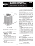
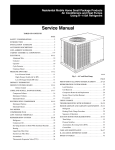
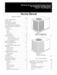
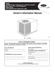
Fig. 1 -- Unit 664B
Cooling Operation . . . . . . . . . . . . . . . . . . . . . . . . . . . . 10, 17
Heating Operation . . . . . . . . . . . . . . . . . . . . . . . . . . . . . . . 17
Continuous Fan . . . . . . . . . . . . . . . . . . . . . . . . . . . . . . . . . 17
Defrost . . . . . . . . . . . . . . . . . . . . . . . . . . . . . . . . . . . . . . . 17
Electric Resistance Heating . . . . . . . . . . . . . . . . . . . . . . . . 17
MAINTENANCE . . . . . . . . . . . . . . . . . . . . . . . . . . . . . . . . 17--20
Air Filter . . . . . . . . . . . . . . . . . . . . . . . . . . . . . . . . . . . . . . . . 18
Unit Top Removal . . . . . . . . . . . . . . . . . . . . . . . . . . . . . . . . . 18
Indoor Blower and Motor . . . . . . . . . . . . . . . . . . . . . . . . . . . 18
Outdoor Coil, Indoor Coil, and Condensate Drain Pan . . . . . 19
Outdoor Fan . . . . . . . . . . . . . . . . . . . . . . . . . . . . . . . . . . . . . 19
Electrical Controls and Wiring . . . . . . . . . . . . . . . . . . . . . . . 19
Refrigerant Circuit . . . . . . . . . . . . . . . . . . . . . . . . . . . . . . . . . 20
Indoor Airflow . . . . . . . . . . . . . . . . . . . . . . . . . . . . . . . . . . . 20
Metering Devices . . . . . . . . . . . . . . . . . . . . . . . . . . . . . . . . . 20
Liquid Line Strainers . . . . . . . . . . . . . . . . . . . . . . . . . . . . . . . 20
High Flow Valves . . . . . . . . . . . . . . . . . . . . . . . . . . . . . . . . . 20
TROUBLESHOOTING . . . . . . . . . . . . . . . . . . . . . . . . . . . . . . 20
START--UP CHECKLIST . . . . . . . . . . . . . . . . . . . . . . . . . . . . 20
Sequence of Operation . . . . . . . . . . . . . . . . . . . . . . . . . . . . . 10
Fan Operation . . . . . . . . . . . . . . . . . . . . . . . . . . . . . . . . . . 10
1
SAFETY CONSIDERATIONS
664B
Installation and servicing of this equipment can be hazardous due
to mechanical and electrical components. Only trained and
qualified personnel should install, repair, or service this equipment.
Untrained personnel can perform basic maintenance functions such
as cleaning and replacing air filters. All other operations must be
performed by trained service personnel. When working on this
equipment, observe precautions in the literature, on tags, and on
labels attached to or shipped with the unit and other safety
precautions that may apply.
Follow all safety codes. Installation must be in compliance with
local and national building codes. Wear safety glasses, protective
clothing, and work gloves. Have fire extinguisher available. Read
these instructions thoroughly and follow all warnings or cautions
included in literature and attached to the unit.
.
Recognize safety information. This is the safety--alert symbol
When you see this symbol on the unit and in instructions or manuals, be alert to the potential for personal injury. Understand these
signal words: DANGER, WARNING, and CAUTION. These
words are used with the safety--alert symbol. DANGER identifies
the most serious hazards which will result in severe personal injury
or death. WARNING signifies hazards which could result in personal injury or death. CAUTION is used to identify unsafe practices which may result in minor personal injury or product and property damage. NOTE is used to highlight suggestions which will
result in enhanced installation, reliability, or operation.
!
WARNING
ELECTRICAL SHOCK HAZARD
Failure to follow this warning could result in personal
injury or death.
Before installing or servicing system, always turn off main
power to system and tag. There may be more than one
disconnect switch. Turn off accessory heater power switch if
applicable.
!
CAUTION
CUT HAZARD
Failure to follow this caution may result in personal injury.
Sheet metal parts may have sharp edges or burrs. Use care
and wear appropriate clothing.
INTRODUCTION
The 664B packaged heat pump is fully self--contained and
designed for outdoor installation (See Fig. 1). Standard units are
shipped in a horizontal--discharge configuration for installation on
a ground--level slab or directly on the ground if local codes permit.
Standard units can be converted to downflow (vertical) discharge
configurations for rooftop applications with a field supplied
plenum.
RECEIVING AND INSTALLATION
Step 1 — Check Equipment
IDENTIFY UNIT
The unit model number and serial number are printed on the unit
informative plate. Check this information against shipping papers.
INSPECT SHIPMENT
Inspect for shipping damage while unit is still on shipping pallet. If
unit appears to be damaged or is torn loose from its anchorage,
have it examined by transportation inspectors before removal.
Forward claim papers directly to transportation company.
Manufacturer is not responsible for any damage incurred in transit.
Check all items against shipping list. Immediately notify the
nearest equipment distribution office if any item is missing. To
prevent loss or damage, leave all parts in original packages until
installation.
Step 2 — Provide Unit Support
For hurricane tie downs, contact distributor for details and PE
(Professional Engineering) Certificate, if required.
SLAB MOUNT
Place the unit on a solid, level concrete pad that is a minimum of 4
in. (102 mm) thick with 2 in. (51 mm) above grade. The slab
should extend approximately 2 in. (51 mm) beyond the casing on
all 4 sides of the unit. Do not secure the unit to the slab except
when required by local codes.
A 6--in. (152 mm) wide gravel apron should be used around the
flat surface to prevent airflow blockage by grass or shrubs. The
unit should be level within 1/4 in. (6 mm). This is necessary for the
unit drain to function properly.
GROUND MOUNT
The unit may be installed either on a slab or placed directly on the
ground if local codes permit. Place the unit on level ground
prepared with gravel for condensate discharge.
Step 3 — Provide Clearances
The required minimum service clearances are shown in Fig. 5.
Adequate ventilation and outdoor air must be provided.
The outdoor fan draws air through the outdoor coil and discharges
it through the top fan grille. Be sure that the fan discharge does not
recirculate to the outdoor coil. Do not locate the unit in either a
corner or under an overhead obstruction. The minimum clearance
under a partial overhang (such as a normal house overhang) is 48
in. (1219 mm) above the unit top. The maximum horizontal
extension of a partial overhang must not exceed 48 in. (1219 mm).
IMPORTANT: Do not restrict outdoor airflow. An air restriction
at either the outdoor--air inlet or the fan discharge may be
detrimental to compressor life.
Do not place the unit where water, ice, or snow from an overhang
or roof will damage or flood the unit. Do not install the unit on
carpeting or other combustible materials. Slab--mounted units
should be at least 4 in. (102 mm) above the highest expected water
and runoff levels. Do not use unit if it has been under water.
Step 4 — Place Unit
Unit can be moved with the rigging holds provided in the unit
base. Refer to Table 1 for operating weights. Use extreme caution
to prevent damage when moving the unit. Unit must remain in an
upright position during all moving operations. The unit must be
level with in 1/4 in. (6 mm) for proper condensate drainage; the
ground--level pad must be level before setting the unit in place.
When a field--fabricated support is used, be sure that the support is
level and that it properly supports the unit.
Step 5 — Select and Install Ductwork
The design and installation of the duct system must be in
accordance with the standards of the NFPA for installation of
non--residence type air conditioning and ventilating systems,
NFPA 90A or residence type, NFPA 90B and/or local codes and
ordinances.
Select and size ductwork, supply--air registers, and return air grilles
according to ASHRAE (American Society of Heating,
Refrigeration, and Air Conditioning Engineers) recommendations.
Use the duct flanges provided on the supply-- and return--air
openings on the side of the unit. See Fig. 5 for connection sizes
and locations. The 14--in. (356 mm) round duct collars are shipped
inside the unit attached to the base pan in the indoor blower
compartment. They are field--installed and must be removed from
the indoor blower compartment prior to start--up, even if they are
not used for installation.
2
When designing and installing ductwork, consider the following:
!
CAUTION
CONFIGURING UNITS FOR DOWNFLOW (VERTICAL)
DISCHARGE
!
UNIT DAMAGE HAZARD
ELECTRICAL SHOCK HAZARD
Failure to follow this caution may result in damage to unit
components.
Failure to follow this warning could result in personal
injury or death.
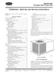
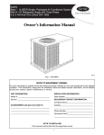
When connecting ductwork to units, do not drill deeper
than 3/4 in. (19 mm) in shaded area shown in Fig. 2 or coil
may be damaged.
19.17 in. (487 mm)
WARNING
Before performing service or maintenance operations on the
system, turn off main power to unit and install lockout tag.
Units are dedicated side supply products. They are not convertible
to vertical air supply. A field--supplied plenum must be used to
convert to vertical air discharge.
3.92 in.
(100 mm)
A08003
Fig. 2 -- Area Not to be Drilled More Than 3/4--in. (19 mm)
Deep
1. All units should have field--supplied filters or accessory
filter rack installed in the return--air side of the unit.
Recommended sizes for filters are shown in Table 1.
2. Avoid abrupt duct size increases and reductions. Abrupt
change in duct size adversely affects air performance.
IMPORTANT: Use flexible connectors between ductwork and
unit to prevent transmission of vibration. Use suitable gaskets to
ensure weather tight and airtight seal. When electric heat is
installed, use fireproof canvas (or similar heat resistant material)
connector between ductwork and unit discharge connection. If
flexible duct is used, insert a sheet metal sleeve inside duct. Heat
resistant duct connector (or sheet metal sleeve) must extend 24--in.
(610 mm) from electric heater element.
3. Size ductwork for cooling air quantity (cfm). The minimum
air quantity for proper electric heater operation is listed in
Table 2. Heater limit switches may trip at air quantities
below those recommended.
4. Seal, insulate, and weatherproof all external ductwork. Seal,
insulate and cover with a vapor barrier all ductwork passing
through conditioned spaces. Follow latest Sheet Metal and
Air Conditioning Contractors National Association
(SMACNA) and Air Conditioning Contractors Association
(ACCA) minimum installation standards for residential
heating and air conditioning systems.
5. Secure all ducts to building structure. Flash, weatherproof,
and vibration--isolate duct openings in wall or roof
according to good construction practices.
Fig. 6 shows a typical duct system with 664B unit installed.
NOTE: When installing condensate drain connection be sure to
comply with local codes and restrictions.
Unit removes condensate through a 1--3/64 in. (27 mm) ID hole
(using 3/4--in. (19 mm) OD piping or tubing) which is located at
the end of the unit. See Fig. 5 for location of condensate
connection.
Condensate water can be drained directly onto the roof in rooftop
installations (where permitted) or onto a gravel apron in ground
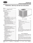
level installations. Install a field--supplied condensate trap at end of
condensate connection to ensure proper drainage. Make sure that
the outlet of the trap is at least 1 in. (25 mm) lower than the drain
pan condensate connection to prevent the pan from overflowing
(See Fig. 3 and 4). When using a gravel apron, make sure it slopes
away from the unit.
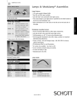
If the installation requires draining the condensate water away from
the unit, install a 2--in. (51 mm) trap using a 3/4--in. (19 mm) OD
tubing or pipe. (See Fig. 3 and 4.) Make sure that the outlet of the
trap is at least 1 in. (25 mm) lower than the unit drain--pan
condensate connection to prevent the pan from overflowing. Prime
the trap with water. Connect a drain tube using a minimum of
3/4--in. (19 mm) PVC, 3/4--in. (19 mm) CPVC, or 3/4--in. copper
pipe (all field supplied). Do not undersize the tube. Pitch the drain
tube downward at a slope of at least 1 in. (25 mm) for every 10 ft
(3 m) of horizontal run. Be sure to check the drain tube for leaks.
Prime trap at the beginning of the cooling season start--up.
Allowable glues for condensate trap connection are: Standard
ABS, CPVC, or PVC cement..
1” (25 mm) MIN.
TRAP
OUTLET
2” (51 mm) MIN.
A08001
Fig. 3 -- Condensate Trap
TRAP
OUTLET
1" (25 mm) MIN.
2" (51 mm) MIN.
Fig. 4 -- PVC Condensate Trap
3
664B
Step 6 — Connect Condensate Drain
664B
A08414
Fig. 5 -- Unit Base Dimensions, 664B024--060
4
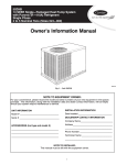
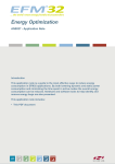
INDOOR
THERMOSTAT
RETURN
AIR
FROM
POWER
SOURCE
TOP COVER
POWER AND
LOW-VOLTAGE
ENTRY
DISCONNECT
PER NEC
(UNIT AND
ELECTRIC
HEATER)
COMPOSITE
RUST-PROOF
BASEPAN
Power Wiring
Control Wiring
CONDENSATE
DRAIN
CONNECTION
Condenser Airflow
Evaporator Airflow
A08207
664B
Fig. 6 -- Typical Installation
Table 1 – Physical Data
UNIT SIZE
024
030
036
042
048
NOMINAL CAPACITY (ton)
2
2--1/2
3
3--1/2
4
5
OPERATING WEIGHT (lb)
(kg)
293
133
324
147
377
171
389
176
384
174
433
196
Scroll
COMPRESSOR
REFRIGERANT (R-- 22)
Quantity (lb)
(kg)
7.5
3.4
060
Ultra Tech Scroll
10.3
4.7
10.3
4.7
11.9
5.4
11.4
5.2
13.3
6.0
AccuRater®
REFRIGERANT METERING DEVICE
TXV
Orifice ID (in.)
0.067
0.067
0.082
0.086
–
–
Orifice OD (in.)
0.049
0.057
0.059
0.063
0.070
0.073
2…21
2…21
2…21
2…21
2…21
2…21
11.1
12.7
15.8
15.8
13.3
15.8
Copper Tubes, Aluminum Plate Fins
CONDENSER COIL
Rows…Fins/in.
Face Area (sq. ft.)
Propeller
CONDENSER FAN
Nominal Cfm
2600
2600
3200
3200
3200
3300
Diameter (in.)
(mm)
20
508
20
508
20
508
20
508
20
508
20
508
1/8 (825)
1/8 (825)
1/4 (1100)
1/4 (1100)
1/4 (1100)
1/2 (1100)
Motor HP (RPM)
Copper Tubes, Aluminum Plate Fins
EVAPORATOR COIL
Rows…Fins/in.
Face Area (sq. ft.)
3…17
3…17
4…17
4…17
4…17
4…17
4.3
4.9
4.9
6.1
4.9
6.1
1400
1600
Direct Drive
Evaporator blower
Nominal Airflow (Cfm)
Size (in.)
(mm)
Motor HP (RPM)
800
1000
1200
10x8
254 x 203
1/2 (1050)
11x9
279 x 229
1/2 (1050)
3/4 (1050)
3/4 (1050)
1 (1050)
1 (1050)
Round
CONNECTING DUCT SIZES
Supply Air (in.)
(mm)
14
356
Return Air (in.)
(mm)
14
356
Return-- Air Filters* Throwaway (in.)
(mm)
1875
11x10
279 x 254
24 x 24
610 x 610
24 x 30
610 x 762
30 x 30
762 x 762
*Required filter sizes shown are based on the ARI (Air conditioning & Refrigeration Institute) rated airflow at a velocity of 300 ft/min (91 m) for throwaway type or
450 ft/min (137 m) for high capacity type. Recommended filters are 1 ---in. (25 mm) thick.
5
Table 2 – Minimum Airflow for Safe Electric Heater Operation
Unit Size
024
030
036
042
048
060
5kW
500
600
600
600
600
600
Minimum Airflow (CFM)
7.5kW
10kW
15kW
650
750
-800
1050
-800
1050
1150
800
1050
1150
800
1050
1150
800
1050
1150
20kW
--1200
1200
1200
1200
Step 7 — Install Electrical Connections
!
WARNING
ELECTRICAL SHOCK HAZARD
664B
Failure to follow this warning could result in personal
injury or death.
The unit cabinet must have an uninterrupted, unbroken
electrical ground to minimize the possibility of personal
injury if an electrical fault should occur. This ground may
consist of an electrical wire connected to the unit ground
screw in the control compartment, or conduit approved for
electrical ground when installed in accordance with NEC,
ANSI/NFPA 70 American National Standards Institute/
National Fire Protection Association (latest edition) (in
Canada, Canadian Electrical Code CSA C22.1) and local
electrical codes.
!
ROUTING POWER LEADS INTO UNIT
Use only copper wire between disconnect and unit. The
high--voltage leads should be in a conduit until they enter the unit;
conduit termination at the unit must be watertight. Run the
high--voltage leads through the hole on the control box side of the
unit (See Fig. 7). When the leads are inside the unit, run leads to
the control box (See Fig. 8). For single--phase units, connect leads
to the black and yellow wires (See Fig. 9).
CONNECTING GROUND LEAD TO UNIT GROUND
Connect the ground lead to the chassis using the unit ground in the
control box (See Fig. 8 and 9).
ROUTING CONTROL POWER WIRES (24--V)
Form a drip--loop with the thermostat leads before routing them
into the unit. Route the thermostat leads through grommeted hole
provided in unit into unit control box (See Fig. 7). Connect
thermostat leads and unit power leads as shown in Fig. 9, 10 and
11.
Route thermostat wires through grommet providing a drip--loop at
the panel. Connect low--voltage leads to the thermostat as shown in
Fig. 10 & 11.
The unit transformer supplies 24--v power for complete system
including accessory electrical heater. Transformer is factory wired
for 230--v operation.
ACCESSORY ELECTRIC HEAT WIRING
Refer to accessory electric heat installation instructions for
information on installing accessory electric heat. Accessory electric
heat wiring is shown in Fig. 17 and 18.
HIGH-VOLTAGE POWER
WIRING ENTRY HOLE
CAUTION
LOW-VOLTAGE WIRING
ENTRY HOLE
(grommet hole)
UNIT COMPONENT DAMAGE HAZARD
Failure to follow this caution may result in damage to the
unit being installed.
1. Make all electrical connections in accordance with NEC
ANSI/NFPA 70 (latest edition) and local electrical codes
governing such wiring. In Canada, all electrical
connections must be in accordance with CSA standard
C22.1 Canadian Electrical Code Part 1 and applicable
local codes. Refer to unit wiring diagram.
2. Use only copper conductor for connections between
field--supplied electrical disconnect switch and unit. DO
NOT USE ALUMINUM WIRE.
3. Be sure that high--voltage power to unit is within
operating voltage range indicated on unit rating plate. On
3--phase units, ensure phases are balanced within 2
percent. Consult local power company for correction of
improper voltage and/or phase imbalance.
4. Do not damage internal components when drilling
through any panel to mount electrical hardware, conduit,
etc.
A08407
Fig. 7 -- Unit Electrical Connection
HIGH--VOLTAGE CONNECTIONS
The unit must have a separate electrical service with a
field--supplied, waterproof disconnect switch mounted at, or within
sight from the unit. Refer to the unit rating plate, NEC and local
codes for maximum fuse/circuit breaker size and minimum circuit
amps (ampacity) for wire sizing.
The field--supplied disconnect may be mounted on the unit over
the high--voltage inlet hole when the standard power and
low--voltage entry points are used. See Fig. 6 and 7 for acceptable
location.
Operation of unit on improper line voltage constitutes abuse and
may cause unit damage that could affect warranty.
6
C
BRN
R
G
RED
Y
GRN
Y1
YEL
O
PNK
HEATER LOW
VOLTAGE PLUG
W2
ORN
W3
WHT
Thermostat
and subbase
VIO
Unit Control
Power
Fig. 11 -- Control Connections (Sizes 048--060)
PRE--START--UP
UNIT GROUND
GROUND
LEAD
!
SINGLE-PHASE L
CONNECTIONS
3-PHASE
CONNECTIONS TO DISCONNECT L
TO DISCONNECT PER NEC
PER NEC
L
BLK
FIRE,
EXPLOSION,
HAZARD
YEL
C00012
C
G
Y
O
BRN
RED
GRN
YEL
W2
ORN
W3
WHT
Thermostat
and subbase
VIO
Unit Control
Power
A05207
Fig. 10 -- Control Connections (Sizes 024--042)
ELECTRICAL
SHOCK
Failure to follow this warning could result in personal
injury or death and/or property damage.
1. Follow recognized safety practices and wear protective
goggles when checking or servicing refrigerant system.
2. Relieve and recover all refrigerant from system before
touching or disturbing anything inside terminal box if
refrigerant leak is suspected around compressor
terminals.
3. Never attempt to repair soldered connection while
refrigerant system is under pressure.
4. Do not use torch to remove any component. System
contains oil and refrigerant under pressure.
5. To remove a component, wear protective goggles and
proceed as follows:
a. Shut off electrical power to unit and install
lockout tag.
b. Relieve and reclaim all refrigerant from system
using both high-- and low--pressure ports.
c. Cut component connecting tubing with tubing
cutter and remove component from unit.
d. Carefully unsweat remaining tubing stubs when
necessary. Oil can ignite when exposed to flame.
BLU
Fig. 9 -- Line Power Connections
R
WARNING
Proceed as follows to inspect and prepare the unit for initial
start--up:
1. Remove all access panels.
2. Read and follow instructions on all DANGER, WARNING,
CAUTION, and INFORMATION labels attached to, or
shipped with unit.
3. Make the following inspections:
a. Inspect for shipping and handling damages, such as
broken lines, loose parts, disconnected wires, etc.
b. Inspect for oil at all refrigerant tubing connections and
on unit base. Detecting oil generally indicates a
refrigerant leak. Leak test all refrigerant tubing
connections using electronic leak detector, or
liquid--soap solution. If a refrigerant leak is detected, see
Check for Refrigerant Leaks section.
7
664B
A05208
A05388
Fig. 8 -- Control Box Wiring
664B
c. Inspect all field-- and factory--wiring connections. Be
sure that connections are completed and tight.
d. Ensure wires do not touch refrigerant tubing or sharp
sheet metal edges.
e. Inspect coil fins. If damaged during shipping and
handling, carefully straighten fins with a fin comb.
4. Verify the following conditions:
a. Make sure that outdoor--fan blade is correctly positioned
in fan orifice. Top edge of blade should be 3.125 in.(79
mm) down from outdoor coil outlet grille (size
024--048, See Fig. 19) or hub should be 0.708--in. (18
mm) away from motor end bell (size 060, See Fig. 19).
See Outdoor Fan Adjustment section.
b. Make sure that air filter is in place.
c. Make sure that condensate drain pan and trap are filled
with water to ensure proper drainage.
d. Make sure that all tools and miscellaneous loose parts
have been removed.
START--UP
Step 1 — Check for Refrigerant Leaks
Proceed as follows to locate and repair a refrigerant leak and to
charge the unit:
1. Locate leak and make sure that refrigerant system pressure
has been relieved and reclaimed from both high-- and
low--pressure ports.
2. Repair leak following accepted practices.
NOTE: Install a filter drier whenever the system has been opened
for repair.
Step 2 — Start--Up Cooling and Make Adjustments
Complete the required procedures given in the Pre--Start--Up
section before starting the unit. Do not jumper any safety devices
when operating the unit. Do not operate the unit in cooling mode
when the outdoor temperature is below 40°F (4.4°C) (unless
accessory low--ambient kit is installed). Do not rapid cycle the
compressor. Allow 5 min. between “on” cycles to prevent
compressor damage.
CHECKING COOLING AND HEATING CONTROL
OPERATION
Start and check the unit for proper cooling control operation as
follows:
1. Place room thermostat SYSTEM switch in OFF position.
Observe that blower motor starts when FAN switch is
placed in ON position and shuts down within 60 sec. (for
024--042) or 90 seconds (for 048 and 060) when FAN
switch is placed in AUTO position.
2. Place SYSTEM switch in COOL position and FAN switch
in AUTO position. Set control below room temperature.
Observe that compressor, outdoor fan, and indoor blower
motors start and that reversing valve shifts. Observe that
cooling cycle shuts down when control setting is satisfied.
Reversing valve (RV) remains energized.
3. Place system switch in HEAT position. Observe that
compressor, indoor fan and outdoor fan energize (Reversing
Valve is deenergized in heat pump heating mode). Set
control above room temperature. Observe that heating cycle
shuts down when control setting is satisfied.
4. When using an automatic changeover room thermostat,
place both SYSTEM and FAN switches in AUTO positions.
Observe that unit operates in Cooling mode when
temperature control is set to call for Cooling (below room
temperature), and unit operates in Heating mode when
temperature control is set to call for Heating (above room
temperature).
Step 3 — Refrigerant Charge
Refrigerant Charge — Amount of refrigerant charge is listed on
unit nameplate and in Table 1. Refer to Bryant Refrigerant Service
Techniques Manual, Refrigerants section. Unit panels must be in
place when unit is operating during charging procedure. Unit must
operate a minimum of 15 minutes before checking charge.
NO CHARGE
Refer to Bryant Refrigerant Service Techniques. Use standard
evacuating techniques. After evacuating system, weigh in the
specified amount of refrigerant (refer to Table 1).
LOW CHARGE COOLING
024--042 units:
1. Measure suction line pressure by attaching a gauge to the
service port.
2. Measure the suction line temperature by attaching a
temperature sensing device to it.
3. Insulate the temperature sensing device so that the outdoor
ambient doesn’t affect the reading.
4. Locate the measured suction line pressure in the top row of
Table 5 and the measured outdoor ambient temperature in
the left column of the table. Based on the two values,
determine the required suction line temperature.
5. If the measured suction line temperature is greater than the
tabulated temperature, add charge in the system.
048 and 060 units:
1. Measure discharge line pressure by attaching a gauge to the
service port.
2. Measure the liquid line temperature by attaching a
temperature sensing device to it.
3. Insulate the temperature sensing device so that the outdoor
ambient doesn’t affect the reading.
4. Refer to the required subcooling in Tables 3 to find the
required subcooling based on the model size and the
outdoor ambient temperature.
5. Interpolate if the outdoor temperature lies in between the
table values. Extrapolate if the temperature lies beyond the
table range.
6. Find the pressure value corresponding to the measured
pressure on the compressor discharge line.
7. Read across from the pressure reading to obtain the Liquid
line temperature for a required subcooling.
8. Add charge if the measured temperature is higher than the
liquid line temperature value in the table.
9. Add charge using the service connection on the suction line
of the compressor.
HEATING MODE CHARGE
Do not attempt to adjust charge by cooling methods while in heat
pump heating mode. Recover refrigerant and weigh in according to
unit data plate refrigerant data.
8
664B
Table 3 – Required Subcooling
A08406
Step 4 — Indoor Airflow and Airflow Adjustments
NOTE: For cooling operation, the recommended airflow is 350
to 450 cfm for each 12,000 Btuh of rated cooling capacity.
Table 4 shows dry coil air delivery for horizontal discharge units.
Tables 6--8 show pressure drops.
NOTE: Be sure that all supply-- and return--air grilles are open,
free from obstructions, and adjusted properly.
!
WARNING
ELECTRICAL SHOCK HAZARD
Failure to follow this warning could result in personal
injury or death.
Disconnect electrical power to the unit and install lockout
tag before changing blower speed.
Airflow can be changed by changing the lead connections at the
blower motor. To change motor speeds, reposition wire at fan
motor speed terminals labeled 1--2--3--4 (refer to Fig. 12).
Remove the speed tap connector labeled 1 through 5 on the motor.
While looking at the connector end that is inserted into the motor,
gently pry the locking tab outward and remove the wire from the
connector. Insert the wire into the desired tap until it locks into
place. Be sure new airflow meets the range noted above and
minimum electric heat CFM, if equipped. Refer to Table 2 and 4.
All model sizes are factory wired or rated airflow operation.
A08412
Fig. 12 -- Motor Speed Selection
FOR 208/230V BLOWER MOTORS
The motor lead speed connections are as follows:
SIZE
024
030
036
042
SIZE
048
060
9
RATED AIRFLOW
Tap 1
Tap 2
Tap 1
Tap 2
RATED AIRFLOW
Low
High
Stage
Stage
Tap 1
Tap 3
Tap 1
Tap 3
HIGH AIRFLOW
Tap 3
Tap 4
Tap 3
Tap 4
HIGH AIRFLOW
Low
High
Stage
Stage
Tap 2
Tap 4
Tap 2
Tap 4
664B
Step 5 — Unit Controls
All compressors have the following internal--protection controls.
HIGH--PRESSURE RELIEF VALVE
This valve opens when the pressure differential between the low
and high side becomes excessive.
LOSS OF CHARGE SWITCH
Located on the outdoor liquid line is a low--pressure switch which
functions as a loss--of--charge switch. This switch contains a
Schrader core depressor. This switch opens at 7 psig and closes at
22 psig. No adjustment is necessary.
COMPRESSOR OVERLOAD
This overload interrupts power to the compressor when either the
current or internal temperature become excessive, and
automatically resets when the internal temperature drops to a safe
level.
This overload may require up to 60 minutes (or longer) to reset;
therefore, if the internal overload is suspected of being open,
disconnect the electrical power to the unit and check the circuit
through the overload with an ohmmeter or continuity tester.
Step 6 — Compressor Rotation
On 3--Phase units it is important to be certain compressor is
rotating in the proper direction. To determine whether or not
compressor is rotating in the proper direction:
1. Connect service gages to suction and discharge pressure
fittings.
2. Energize the compressor.
3. The suction pressure should drop and the discharge pressure
should rise, as is normal on any start--up.
If the suction pressure does not drop and the discharge pressure
does not rise to normal levels:
1. Turn off power to the unit and tag disconnect.
2. Reverse any two of the unit power leads.
3. Turn on power to the unit.
The suction and discharge pressure levels should now move to
their normal start--up levels.
NOTE: When the compressor is rotating in the wrong direction,
the unit makes an elevated level of noise and does not provide
cooling.
Step 7 — Sequence of Operation
FAN OPERATION
The FAN switch on the thermostat controls indoor fan operation.
When the FAN switch is placed in the ON position, the IFR
(indoor--fan relay) is energized through the G terminal on the
thermostat. The normally--open contacts close, which then provide
power to the indoor (evaporator) fan motor (IFM). The IFM will
run continuously when the FAN switch is set to ON.
When the FAN switch is set to AUTO, the thermostat deenergizes
the IFR (provided there is not a call for cooling). The contacts open
and the IFM is deenergized. The IFM will be energized only when
there is a call for cooling, in heat pump heating mode or if the unit
is equipped with accessory electric heat, the indoor--fan motor will
also run while the accessory electric heat is energized.
NOTE: Some units are equipped with a time--delay relay. On
these units, the indoor fan remains on for 30 seconds after G or Y
is deenergized.
COOLING OPERATION (SIZES 024--042)
With a call for cooling (Y/Y2), the indoor fan energizes
immediately whereas the contactor energizes after a 5 minute time
delay (in case of initial start--up) starting the compressor and the
outdoor fan motor. When the cooling demand is met, Y/Y2
de--energizes, shutting the compressor, indoor fan and the outdoor
fan.
COOLING OPERATION (SIZES 048 AND 060)
These units utilize a 2 stage indoor thermostat. With a first stage
call for cooling (Y1), the indoor fan (low stage) energizes
immediately whereas the contactor energizes after a 5 minute time
delay (in case of an initial start--up) starting the compressor (low
stage) and the outdoor fan motor. If the low stage operation cannot
satisfy the cooling demand, the second stage cooling (Y2)
energizes switching the compressor into high stage cooling through
energizing an internal solenoid valve inside the scroll compressor
and switching the indoor fan into high stage. When second stage
cooling is satisfied, Y2 de--energizes switching the compressor and
the indoor fan into low stage cooling. When the low stage cooling
demand is met, Y1 de--energizes shutting the compressor, indoor
fan and the outdoor fan.
HEATING OPERATION (SIZES 024--042)
With a call for heating (Y1), the indoor fan (low stage) energizes
immediately whereas the contactor energizes after a 5 minute time
delay (in case of initial start--up) starting the compressor and the
outdoor fan motor. If Y/Y2 cannot satisfy the heating demand, the
auxiliary or backup heat (W2) energizes. In case of staged heating,
W3 is energized if the demand is not met. The highest airflow
selected is run while the electric heat is in operation. When heating
demand is met, W3, W2 and Y/Y2 sequentially de--energize
shutting the compressor, indoor fan and the outdoor fan.
HEATING OPERATION (SIZES 048 AND 060)
With a first stage call for heating (Y1), the indoor fan (low stage)
energizes immediately whereas the contactor energizes after a 5
minute time delay (in case of initial start--up) starting the
compressor (low stage) and the outdoor fan motor. If the low stage
oepration cannot satisfy the heating demand, the second stage
heating (Y2) energizes switching the compressor into high stage
heating through energizing an internal solenoid valve inside the
scroll compressor and switching the indoor fan into high stage. The
auxiliary or backup heat is controlled by a third stage (W2). If the
demand is not met, W3 is energized in case of staged heating.
When heating demand is satisfied, W3, W2 and Y2 sequentially
de--energize switching the compressor and the indoor fan into low
stage heating. When the low stage heating demand is met, Y1
de--energizes shutting the compressor, indoor fan and the outdoor
fan.
CONTINUOUS FAN
With the continuous Indoor fan option selected on the thermostat,
G is continuously energized. In case of 024--042 units, the selected
airflow setting is provided. In case of 048 and 060 units, the
system runs low stage (Y1) airflow for continuous fan operation.
DEFROST
Defrost board (DB) is a time and temperature control, which
includes a field--selectable time period between checks for defrost
(30, 60, 90 and 120 minutes). The time period is factory--set at 60
minutes and should only be adjusted by a trained service person.
Electronic timer and defrost cycle start only when contactor is
energized and defrost thermostat (DFT) is closed.
Defrost mode is identical to Cooling mode. The outdoor fan motor
stops because of “OF1” and “OF2” contacts opening on the defrost
board, a bank of optional electric heat turns on to warm air
supplying the conditioned space.
ELECTRIC RESISTANCE HEATING
If accessory electric heaters are installed, on a call for “Emergency
Heat” the thermostat energizes W which energizes the heater relay
and in turn energizes the electric heaters. The IFR is energized
which starts the indoor--fan motor. If the heaters are staged, W2 is
energized when the second stage of heating is required. When the
need for heating is satisfied, the heater and IFM are de--energized.
10
664B
A08209
Fig. 13 -- Typical Single--Phase Unit Electrical Diagram (Sizes 024--042)
11
664B
A06405
Fig. 14 -- Typical Single--Phase Unit Electrical Diagram (Sizes 048--060)
12
664B
A06325
Fig. 15 -- Typical Three--Phase Unit Electrical Diagram (Sizes 030--042)
13
664B
A06326
Fig. 16 -- Typical Three--Phase Unit Electrical Diagram (Sizes 048--060)
14
664B
A05209
Fig. 17 -- Single--Phase Accessory Electric Heater Wiring
A06327
Fig. 18 -- Three--Phase Accessory Electric Heater Wiring
15
Table 4 – Dry Coil Air Delivery* Horizontal Discharge
(Deduct 10 percent for 208 Volt Operation)
230 VOLT HORIZONTAL DISCHARGE
UNIT
SIZE
SPEED
TAP
1
024
2
2
030
3
1
036
2
3
042
664B
4
1
2
048
3
4
1
2
060
3
4
AIR
DELIVERY
Watts
CFM
Watts
CFM
Watts
CFM
Watts
CFM
Watts
CFM
Watts
CFM
Watts
CFM
Watts
CFM
Watts
CFM
Watts
CFM
Watts
CFM
Watts
CFM
Watts
CFM
Watts
CFM
Watts
CFM
Watts
CFM
0.1
—
—
—
—
—
—
—
—
180
1344
—
—
269
1440
—
—
—
—
—
—
386
1680
—
—
224
1334
—
—
608
1931
737
2093
0.2
99
848
—
—
155
1108
—
—
166
1215
—
—
283
1404
—
—
204
1129
—
—
398
1652
440
1745
235
1288
—
—
626
1900
755
2061
0.3
100
793
—
—
146
995
—
—
179
1172
—
—
305
1369
418
1572
209
1087
233
1164
409
1625
448
1717
251
1259
286
1333
643
1878
770
2028
EXTERNAL STATIC PRESSURE (IN. WC)
0.4
0.5
0.6
0.7
118
130
142
—
757
698
632
—
—
—
222
233
—
—
970
918
157
170
—
—
951
884
—
—
—
—
261
275
—
—
1117
1053
191
204
216
—
1136
1095
1051
—
261
276
290
301
1343
1304
1272
1234
321
336
349
360
1333
1301
1273
1239
432
450
465
480
1543
1504
1475
1441
216
229
236
249
1027
994
932
881
245
254
266
276
1122
1066
1025
954
418
425
435
438
1583
1555
1515
1477
457
462
469
477
1684
1651
1612
1573
266
277
291
298
1224
1181
1157
1117
301
311
325
333
1296
1261
1232
1199
660
668
685
697
1844
1817
1789
1755
787
799
817
826
2001
1971
1934
1899
0.8
—
—
244
861
—
—
286
1014
—
—
316
1190
—
—
490
1418
—
—
289
906
441
1444
480
1537
—
—
344
1170
—
—
812
1850
0.9
—
—
257
795
—
—
291
980
—
—
329
1148
—
—
503
1380
—
—
—
—
451
1403
485
1508
—
—
370
1062
—
—
782
1757
1.0
—
—
260
729
—
—
315
877
—
—
342
1100
—
—
518
1332
—
—
—
—
—
—
486
1470
—
—
—
—
—
—
—
—
*Air delivery values are based on operating voltage of 230v, wet coil, without filter or electric heater. Deduct filter and electric heater pressure drops to obtain
static pressure available for ducting.
NOTES:
1. Do not operate the unit at a cooling airflow that is less than 350 cfm for each 12,000 Btuh of rated cooling capacity. Evaporator coil frosting may occur at airflows below this point.
2. Dashes indicate portions of table that are beyond the blower motor capacity or are not recommended.
16
Table 5 – Cooling Charging Chart
OD Temp.
(°F)
45
55
65
75
85
95
105
115
125
OD Temp.
(°C)
7
13
18
24
29
35
41
46
52
52
54
56
59
61
64
67
73
76
79
82
85
89
92
51
—
—
—
—
—
—
—
—
55
—
—
—
—
—
—
—
—
60
53
—
—
—
—
—
—
—
64
57
—
—
—
—
—
—
—
69
—
—
—
—
62
66
70
—
—
53
57
62
66
71
—
—
—
56
61
—
—
—
—
53
—
—
—
—
—
—
—
—
—
—
—
—
—
—
—
—
—
—
—
—
SUCTION LINE TEMPERATURE (°C)
Suction Line Pressure (kPa)
—
—
75
66
58
50
—
—
—
—
—
—
71
63
54
50
49
—
—
—
—
76
67
58
53
52
50
—
—
—
—
72
62
57
55
53
—
—
—
—
—
66
60
58
56
—
—
—
—
—
—
64
61
59
361
370
387
405
423
442
462
482
502
523
544
566
589
612
636
11
—
—
—
—
—
—
—
—
13
—
—
—
—
—
—
—
—
15
12
—
—
—
—
—
—
—
18
14
—
—
—
—
—
—
—
21
16
12
—
—
—
—
—
—
—
19
14
—
—
—
—
—
—
—
21
17
—
—
—
—
—
—
—
—
19
13
—
—
—
—
—
—
—
21
16
12
—
—
—
—
—
—
24
19
14
10
—
—
—
—
—
—
22
17
12
10
9
—
—
—
—
24
20
14
12
11
10
—
—
—
—
22
17
14
13
11
—
—
—
—
—
19
16
14
13
—
—
—
—
—
—
18
16
15
MAINTENANCE
!
To ensure continuing high performance, and to minimize the
possibility of premature equipment failure, periodic maintenance
must be performed on this equipment. This unit should be
inspected at least once each year by a qualified service person. To
troubleshoot unit, refer to Troubleshooting Chart in back of book.
NOTE TO EQUIPMENT OWNER: Consult your local dealer
about the availability of a maintenance contract.
!
PERSONAL
HAZARD
AND
UNIT
WARNING
ELECTRICAL SHOCK HAZARD
Failure to follow these warnings could result in personal
injury or death:
1. Turn off electrical power to the unit before performing
any maintenance or service on this unit.
2. Use extreme caution when removing panels and parts.
3. Never place anything combustible either on or in contact
with the unit.
WARNING
INJURY
70
DAMAGE
Failure to follow this warning could result in personal
injury or death and possible unit component damage.
The ability to properly perform maintenance on this
equipment requires certain expertise, mechanical skills,
tools and equipment. If you do not possess these, do not
attempt to perform any maintenance on this equipment,
other than those procedures recommended in the Owner’s
Manual.
The minimum maintenance requirements for this equipment are as
follows:
1. Inspect air filter(s) each month. Clean or replace when
necessary.
2. Inspect indoor coil, drain pan, and condensate drain each
cooling season for cleanliness. Clean when necessary.
3. Inspect blower motor and wheel for cleanliness each
cooling season. Clean when necessary.
4. Check electrical connections for tightness and controls for
proper operation each cooling season. Service when
necessary.
5. Ensure electric wires are not in contact with refrigerant
tubing or sharp metal edges.
Step 1 — Air Filter
IMPORTANT: Never operate the unit without a suitable air filter
in the return--air duct system. Always replace the filter with the
same dimensional size and type as originally installed. See Table 1
for recommended filter sizes.
Inspect air filter(s) at least once each month and replace
(throwaway--type) or clean (cleanable--type) at least twice during
each cooling season and twice during the heating season, or
whenever the filter becomes clogged with dust and lint.
Step 2 — Unit Top Removal
NOTE: When performing maintenance or service procedures that
require removal of the unit top, be sure to perform all of the routine
maintenance procedures that require top removal, including coil
inspection and cleaning, and condensate drain pan inspection and
cleaning.
!
WARNING
ELECTRICAL SHOCK HAZARD
Failure to follow this warning could result in personal
injury or death.
Disconnect and tag electrical power to the unit before
removing top.
17
664B
SUCTION LINE TEMPERATURE (°F)
Suction Line Pressure (PSIG)
Only qualified service personnel should perform maintenance and
service procedures that require unit top removal.
Refer to the following top removal procedures:
1. Remove screws on unit top cover surface. (Save all screws.)
2. Remove screws on unit top cover flange. (Save all screws.)
3. Lift top from unit carefully. Set top on edge and make sure
that top is supported by unit side that is opposite duct (or
plenum) side.
4. Carefully replace and secure unit top to unit, using screws
removed in Steps 1 and 2, when maintenance and/or service
procedures are completed.
2. Remove the blower wheel from the housing:
a. Loosen the set screw which secures the wheel to the
motor shaft.
b. Loosen the three mounting legs of the motor by
removing the bolts that fasten themounting legs to the
housing.
c. Slide out the motor assembly (motor, belly band and the
3 mounting legs) from the hub of the wheel.
d. Remove the filler panel at the discharge end of the
blower housing by removing the two screws that fasten
it to the housing.
e. Remove the wheel form the housing.
3. Remove the caked on dirt from the wheel and the motor
using a brush.
4. Remove lint and dirt accumulations from the wheel and
housing with a vacuum cleaner, using a soft brush
attachment.
5. Remove grease and oil with a mild solvent.
6. Reassemble
a. Slip the wheel back in the housing with the hub set
screw parented in the correct direction.
b. Install the filler panel.
c. Reinsert the motor assembly in the wheel hub and align
the mounting legs with the housing mounting hold
locations.
d. Tighten the mounting bolts to fasten the motor assembly
with the housing.
e. Center the wheel in the housing by sliding it, align the
flat end of the shaft with the set screw and tighten the
set screw.
f. Slide back the blower housing into the mounting rails in
the duct panel and install the mounting bracket back in
its position.
g. Install the screws on the external side of the duct panel
to fasten duct panel with the housing.
h. Replace the side access panel.
Step 3 — Indoor Blower and Motor
For longer life, operating economy, and continuing efficiency,
clean accumulated dirt and grease from the blower wheel and
motor annually.
664B
!
WARNING
ELECTRICAL SHOCK HAZARD
Failure to follow this warning could result in personal
injury or death.
Disconnect and tag electrical power to the unit before
cleaning and lubricating the blower motor and wheel.
To clean the blower wheel:
1. Remove the blower housing:
a. Remove the screws on the external side of the duct
panel that fasten the housing to the duct panel assembly.
b. Remove the side access panel and unscrew the
mounting bracket that fastens the blower housing to the
internal partition panel fo the control box assembly.
c. Make sure that the blower housing is supported by hand
before completely removing the mounting bracket.
d. Slide the blower housing from the rails of the duct panel
and place it outside the unit.
Table 6 – Wet Coil Pressure Drop
UNIT
SIZE
024
030
036
042
048
060
600
.027
------
700
.034
.036
-----
800
040
.042
-----
900
.047
.050
.050
----
1000
.053
.055
.055
.042
---
1100
-.063
.063
.049
---
STANDARD CFM (S.C.F.M.)
1200
1300
1400
---.072
.081
-.072
.081
.090
.052
.059
.065
.072
.081
.090
----
1500
--.097
.071
.097
.071
1600
---.078
.108
.078
1700
---.085
.120
.085
1800
---.091
.129
.091
1900
----.139
.098
2000
-----.114
Table 7 – Filter Pressure Drop (in. wc)
UNIT SIZE
024-- 036
042-- 060
FILTER
SIZE in.
(mm)
24 x 24
610 x 610
30 x 30
762 x 762
CFM
500
600
700
800
900 1000 1100 1200 1300 1400 1500 1600 1700 1800 1900 2000 2100 2200 2300
0.06 0.07 0.08 0.08 0.09 0.09 0.09 0.10 0.11 0.12 0.14 0.15
—
—
—
—
—
—
—
—
—
—
—
—
—
—
—
0.08 0.09 0.10 0.11 0.12 0.13 0.14 0.15 0.16 0.17 0.18
Table 8 – Accessory Electric Heat Pressure Drop (in. wc)
CFM
HEATER
kW
600
800
1000
1200
1400
1600
1800
2000
2200
5-- 20
0.06
0.08
0.10
0.13
0.15
0.18
0.20
0.23
0.25
18
Inspect the condenser coil, evaporator coil, and condensate drain
pan at least once each year.
The coils are easily cleaned when dry; therefore, inspect and clean
the coils either before or after each cooling season. Remove all
obstructions, including weeds and shrubs, that interfere with the
airflow through the condenser coil.
Straighten bent fins with a fin comb. If coated with dirt or lint,
clean the coils with a vacuum cleaner, using the soft brush
attachment. Be careful not to bend the fins. If coated with oil or
grease, clean the coils with a mild detergent and water solution.
Rinse coils with clear water, using a garden hose. Be careful not to
splash water on motors, insulation, wiring, or air filter(s). For best
results, spray condenser coil fins from inside to outside the unit. On
units with an outer and inner condenser coil, be sure to clean
between the coils. Be sure to flush all dirt and debris from the unit
base.
Inspect the drain pan and condensate drain line when inspecting
the coils. Clean the drain pan and condensate drain by removing all
foreign matter from the pan. Flush the pan and drain trough with
clear water. Do not splash water on the insulation, motor, wiring, or
air filter(s). If the drain trough is restricted, clear it with a
“plumbers snake” or similar probe device.
Step 5 — Outdoor Fan
!
Remove access panel to locate all the electrical controls and wiring.
Check all electrical connections for tightness. Tighten all screw
connections. If any smoky or burned connections are noticed,
disassemble the connection, clean all the parts, re--strip the wire
end and reassemble the connection properly and securely.
Check to ensure no wires are touching refrigerant tubing or sharp
sheet metal edges. Move and secure wires to isolate from tubing
and sheet metal edges.
After inspecting the electrical controls and wiring, replace all the
panels. Start the unit, and observe at least one complete cooling
cycle to ensure proper operation. If discrepancies are observed in
operating cycle, or if a suspected malfunction has occurred, check
each electrical component with the proper electrical
instrumentation. Refer to the unit wiring label when making these
checks.
Step 7 — Refrigerant Circuit
Inspect all refrigerant tubing connections and the unit base for oil
accumulation annually. Detecting oil generally indicates a
refrigerant leak.
If oil is detected or if low performance is suspected, leak test all
refrigerant tubing using an electronic leak detector, or liquid--soap
solution. If a refrigerant leak is detected, refer to Check for
Refrigerant Leaks section.
If no refrigerant leaks are found and low performance is suspected,
refer to Checking and Adjusting Refrigerant Charge section.
Step 8 — Indoor Airflow
CAUTION
UNIT OPERATION HAZARD
Failure to follow this caution may result in damage to unit
components.
Keep the condenser fan free from all obstructions to ensure
proper cooling operation. Never place articles on top of
unit.
1. Shut off unit power supply and install lockout tag.
2. Remove outdoor--fan assembly (grille, motor, motor cover,
and fan) by removing screws and flipping assembly onto
unit top cover.
3. Loosen fan hub setscrews.
4. Adjust fan height as shown in Fig. 19.
5. Tighten setscrews.
6. Replace outdoor--fan assembly.
The heating and/or cooling airflow does not require checking
unless improper performance is suspected. If a problem exists, be
sure that all supply-- and return--air grilles are open and free from
obstructions, and that the air filter is clean.
Step 9 — Metering Devices
Refrigerant cooling metering device is an AccuRater (024--042) or
TXV (048 and 060) located upstream of the indoor coil distributor
assembly. Refrigerant heating mode metering device is an
AccuRater located upstrem of the outdoor coil distributor
assembly.
Step 10 — Liquid Line Strainers
The liquid line strainers (to protect metering devices) are made of
wire mesh and are located in the liquid lines on the inlet side of the
metering devices.
Step 11 — High Flow Valves
High flow valves are located on the compressor hot gas and suction
tubes. Large black plastic caps distinguish these valves with
O--rings located inside the caps. These valves can not be accessed
for service in the field. Ensure the plastic caps are in place and tight
or the possibility of refrigerant leakage could occur.
TROUBLESHOOTING
15/32-in. (12 mm)
Refer to the Troubleshooting Chart (Table 9) for troubleshooting
information.
START--UP CHECKLIST
A08004
Fig. 19 -- Outdoor Fan Adjustment
Use the Start--Up Checklist at the back of this manual.
Step 6 — Electrical Controls and Wiring
Inspect and check the electrical controls and wiring annually. Be
sure to turn off the electrical power to the unit.
19
664B
Step 4 — Outdoor Coil, Indoor Coil, and
Condensate Drain Pan
OUTDOOR COIL
INDOOR COIL
B
LCS
STRAINER
COMPRESSOR
ACCUMULATOR
A
D
Check Valves
664B
STRAINER
A
Open
B
Closed
C
Open
D
Closed
C
LEGEND
Loss of Charge Switch
LCS
Acutrol
Metering Device
Check Valve (Arrow indicates direction of flow)
HEATING CYCLE
1. Hot gas from compressor flows through the 4-way valve and is
directed to the cooling liquid line check valve. It is then condensed
and directed through subcooling circuits and out to the strainer
and the check valve in the heating liquid line.
2. The refrigerant then feeds the outdoor coil through the Acutrol
metering device on each circuit.
3. Each circuit evaporates the refrigerant and the circuits are combined in the outdoor header with some of the circuits flowing through
the check valve.
4. The refrigerant then flows through the 4-way valve, accumulator,
and back to the compressor.
C95045
Fig. 20 -- Typical Heat Pump Operation, Heating Mode
OUTDOOR COIL
INDOOR COIL
B
LCS
STRAINER
COMPRESSOR
ACCUMULATOR
A
D
Check Valves
STRAINER
A
Closed
B
Open
C
Closed
D
Open
C
LEGEND
LCS
Loss of Charge Switch
Acutrol
Metering Device
Check Valve (Arrow indicates direction of flow)
COOLING CYCLE
1. Hot gas from compressor flows through the 4-way valve and is
directed to the heating liquid line check valve. It is then condensed and subcooled through converging circuits. Refrigerant leaves
the outdoor coil by way of the strainer and the check valve in the
cooling liquid line.
2. The refrigerant then feeds the indoor coil through the Acutrol
metering device on each circuit.
3. Each circuit evaporates the refrigerant and the circuits are combined in the indoor coil header with some of the circuits flowing
through the check valve.
4. The refrigerant then flows through the 4-way valve, accumulator,
and back to the compressor.
C95044
Fig. 21 -- Typical Heat Pump Operation, Cooling Mode
20
Table 9 – Troubleshooting Chart
Compressor and outdoor fan
will not start
Compressor will not start but condenser fan
runs
Three--phase scroll compressor (size 030-060 unit) has a low pressure differential
Compressor cycles (other than normally satisfying) cooling/heating calls
Compressor operates continuously
Excessive head pressure
Head pressure too low
Excessive suction pressure
Suction pressure too low
CAUSE
REMEDY
Power failure
Call power company
Fuse blown or circuit breaker tripped
Replace fuse or reset circuit breaker
Defective contactor, transformer, control relay, or
high--pressure, loss-of--charge or low--pressure switch
Replace component
Insufficient line voltage
Determine cause and correct
Incorrect or faulty wiring
Check wiring diagram and rewire correctly
Thermostat setting too low/too high
Reset Thermostat setting
Faulty wiring or circuit
Loose connections in compressor
Check wiring and repair or replace
Compressor motor burned out, seized, or
Determine cause
internal overload open
Replace compressor
Defective run capacitor, overload, or PTC (positive
temperature coefficient) thermistor
Determine cause and replace
One leg of 3--phase power dead
Replace fuse or reset circuit breaker
Determine cause
Low input voltage
Determine cause and correct
Scroll compressor is rotating in the wrong direction
Correct the direction of rotation by reversing the
3--phase power leads to the unit
Refrigerant overcharge or undercharge
Recover refrigerant, evacuate system, and recharge to capacities shown on rating plate
Defective compressor
Replace and determine cause
Insufficient line voltage
Determine cause and correct
Blocked outdoor coil
Determine cause and correct
Defective run/start capacitor, overload or start relay
Determine cause and replace
Faulty outdoor fan motor or capacitor
Replace
Restriction in refrigerant system
Locate restriction and remove
Dirty air filter
Replace filter
Unit undersized for load
Decrease load or increase unit size
Thermostat temperature set too low
Reset Thermostat setting
Low refrigerant charge
Locate leak, repair, and recharge
Air in system
Recover refrigerant, evacuate system, and recharge
Outdoor coil dirty or restricted
Clean coil or remove restriction
Dirty air filter
Replace filter
Dirty indoor or outdoor coil
Clean coil
Refrigerant overcharged
Recover excess refrigerant
Air in system
Recover refrigerant, evacuate system, and recharge
Indoor or outdoor air restricted or air short--cycling
Determine cause and correct
Low refrigerant charge
Restriction in liquid tube
High Heat load
Reversing valve hung up or leaking internally
Refrigerant overcharged
Dirty air filter
Low refrigerant charge
Metering device or low side restricted
Insufficient coil airflow
Temperature too low in conditioned area
Outdoor ambient below 55°F (13°C)
Filter drier restricted
Check for leaks, repair and recharge
Remove restriction
Check for source and eliminate
Replace valve
Recover excess refrigerant
Replace filter
Check for leaks, repair and recharge
Remove source of restriction
Check filter–replace if necessary
Reset Thermostat setting
Install low--ambient kit
Replace
21
664B
SYMPTOM
START--UP CHECKLIST
(REMOVE AND STORE IN JOB FILE)
I. PRELIMINARY INFORMATION
Model No ............................................................................................................................................................
Serial No .............................................................................................................................................................
Date .....................................................................................................................................................................
Technician ..........................................................................................................................................................
Customer Information(Name/Address) .....................................................................................................................
664B
II. PRE--START--UP
____ Verify that all packing materials have been removed from unit.
____ Verify that condensate connection is installed per installation instructions.
____ Check all electrical connections and terminals for tightness.
____ Check wire proximity to refrigerant tubes and sheet metal edges.
____ Check that indoor (indoor) air filter is clean and in place.
____ Verify that unit installation is level.
____ Check fan wheel propeller for location in housing and setscrew tightness.
III. START--UP
Supply Voltage: L1--L2 __________ L2--L3 __________ L3--L1 __________
Compressor Amps: L1(C) __________ L2(S) __________ L3(R) __________
Indoor Fan Amps: __________ Outdoor Fan Amps: __________
TEMPERATURE--Cooling Mode
Outdoor Air Temperature: __________ DB ____________WB
Return--Air Temperature: __________ DB __________ WB
Cooling Supply Air: __________DB___________WB
PRESSURES--Cooling Mode
Refrigerant Suction __________ psig
Suction Line Temp* ___________
Refrigerant Discharge __________ psig
Discharge Temp{__________
TEMPERATURE--Heating Mode
Outdoor Air Temperature: __________ DB ____________WB
Return--Air Temperature: __________ DB __________ WB
Cooling Supply Air: __________DB___________WB
PRESSURES--Heating Mode
Refrigerant Suction __________ psig
Suction Line Temp* ___________
Refrigerant Discharge __________ psig
Discharge Temp{__________
____ Verify Refrigerant charge using charging tables
*Measured at suction inlet to compressor
{Measured at liquid line leaving outdoor coil
E2008 Bryant Heating & Cooling Systems D 7310 W. Morris St. D Indianapolis, IN 46231
Printed in U.S.A.
Edition Date: 08/08
Manufacturer reserves the right to discontinue, or change at any time, specifications or designs without notice and without incurring obligations.
22
Catalog No. II664B---04
Replaces: II664B--- 24--- 3