1
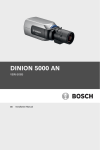
FLEXIDOME 5000 AN
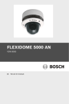
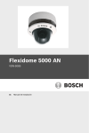
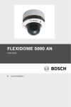
VDN-5085
en
Installation Manual
FLEXIDOME 5000 AN
Table of Contents | en
3
Table of Contents
1
Safety
5
1.1
Safety precautions
5
1.2
Important safety instructions
6
1.3
Connection in outdoor applications
7
1.3.1
Safety precautions
7
1.4
Important notices
8
1.5
FCC information
9
1.6
UL certification
10
1.7
Bosch notice
10
2
Introduction
11
2.1
Features
11
3
Installation
12
3.1
Unpacking
12
3.2
Disassembly
13
3.3
Mounting the unit
14
3.3.1
Mounting tips
15
3.3.2
Flush mounting
15
3.3.3
Surface mounting
16
4
Connection and set-up
19
4.1
Power and video connections
19
4.2
Setting up the camera
20
4.2.1
Camera positioning
20
4.2.2
Menu navigation
21
4.2.3
Focal length and focus
23
4.2.4
Heater
23
4.2.5
Closing the unit
24
5
Configuration
25
5.1
Menus
25
5.1.1
Top level menus
25
5.1.2
Menu navigation
26
5.2
Pre-defined modes
27
Bosch Security Systems
Installation Manual
AM18-Q0648 | v1.0 | 2013.03
4
en | Table of Contents
FLEXIDOME 5000 AN
5.3
Day/Night switching
28
5.4
Camera control communication (Bilinx)
28
5.5
Main menu structure
29
5.5.1
Mode submenu
29
5.5.2
Exposure submenu
30
5.5.3
Day/Night submenu
32
5.5.4
Enhance / Dynamic Engine submenu
34
5.5.5
Color submenu
36
5.5.6
VMD submenu
37
5.5.7
Image Adjustment submenu
38
5.6
Install menu structure
39
5.6.1
Language submenu
40
5.6.2
Lens Wizard submenu
40
5.6.3
Synchronization submenu
41
5.6.4
Connections submenu
41
5.6.5
Test signal submenu
42
5.6.6
Camera ID submenu
42
5.6.7
Privacy masking submenu
44
5.6.8
Flip submenu
44
5.6.9
Defaults submenu
45
6
Troubleshooting
46
6.1
Resolving problems
46
6.2
Customer service
47
7
Maintenance
48
7.1
Repairs
48
7.1.1
Transfer and disposal
48
8
Technical Data
49
8.1
Specifications
49
8.1.1
Dimensions
51
8.1.2
Accessories
53
AM18-Q0648 | v1.0 | 2013.03
Installation Manual
Bosch Security Systems
FLEXIDOME 5000 AN
Safety | en
1
Safety
1.1
Safety precautions
5
DANGER!
High risk: This symbol indicates an imminently hazardous
situation such as "Dangerous Voltage" inside the product.
If not avoided, this will result in an electrical shock, serious
bodily injury, or death.
WARNING!
Medium risk: Indicates a potentially hazardous situation.
If not avoided, this could result in minor or moderate bodily
injury.
CAUTION!
Low risk: Indicates a potentially hazardous situation.
If not avoided, this could result in property damage or risk of
damage to the unit.
Bosch Security Systems
Installation Manual
AM18-Q0648 | v1.0 | 2013.03
6
en | Safety
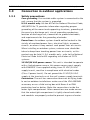
1.2
FLEXIDOME 5000 AN
Important safety instructions
Read, follow, and retain for future reference all of the following
safety instructions. Heed all warnings on the unit and in the
operating instructions before operating the unit.
1.
Cleaning - Generally, using a dry cloth for cleaning is
sufficient but a moist, fluff-free cloth or leather shammy
may also be used. Do not use liquid cleaners or aerosol
cleaners.
2.
Heat Sources - Do not install the unit near any heat
sources such as radiators, heaters, stoves, or other
equipment (including amplifiers) that produce heat.
3.
Water - Never spill liquid of any kind on the unit.
4.
Lightning - Take precautions to protect the unit from
power and lightning surges.
5.
Controls adjustment - Adjust only those controls specified
in the operating instructions. Improper adjustment of
other controls may cause damage to the unit.
6.
Power sources - Operate the unit only from the type of
power source indicated on the label.
7.
Servicing - Unless qualified, do not attempt to service this
unit yourself. Refer all servicing to qualified service
personnel.
8.
Replacement parts - Use only replacement parts specified
by the manufacturer.
9.
Installation - Install in accordance with the manufacturer's
instructions and in accordance with applicable local codes.
10. Attachments, changes or modifications - Only use
attachments/accessories specified by the manufacturer.
Any change or modification of the equipment, not
expressly approved by Bosch, could void the warranty or,
in the case of an authorization agreement, authority to
operate the equipment.
AM18-Q0648 | v1.0 | 2013.03
Installation Manual
Bosch Security Systems
FLEXIDOME 5000 AN
1.3
1.3.1
Safety | en
7
Connection in outdoor applications
Safety precautions
Coax grounding: If an outside cable system is connected to the
unit, ensure that the system is grounded.
U.S.A. models only: Section 810 of the National Electrical Code,
ANSI/NFPA No.70, provides information regarding proper
grounding of the mount and supporting structure, grounding of
the coax to a discharge unit, size of grounding conductors,
location of discharge unit, connection to ground electrodes,
and requirements for the grounding electrode.
Power lines: An outdoor system should not be located in the
vicinity of overhead power lines, electrical lights, or power
circuits, or where it may contact such power lines or circuits.
When installing an outdoor system, extreme care should be
taken to keep from touching power lines or circuits, as this
contact may be fatal. U.S.A. models only - refer to the National
Electrical Code Article 820 regarding installation of CATV
systems.
12 VDC/24 VAC power source: This unit is intended to operate
with a limited power source, this power source must comply
with EN60950. User supplied wiring, from 12 VDC/24 VAC
supply to unit, must be in compliance with electrical codes
(Class 2 power levels). Do not ground the 12 VDC/24 VAC
supply at the terminals or at the unit's power supply terminals.
Connection: The unit has connection terminals on flying leads.
In wet or outdoor installations make use of the VDA-455SMB
accessory or use a field wiring box with Nema 4 or IP66
protection level or better. Make the connections inside the
water tight compartment. After connections are made ensure
that the watertight compartment is tightly closed and cables
and conduits are properly sealed to prevent ingress of water.
Bosch Security Systems
Installation Manual
AM18-Q0648 | v1.0 | 2013.03
8
en | Safety
1.4
FLEXIDOME 5000 AN
Important notices
Disposal - Your Bosch product was developed and
manufactured with high-quality material and components that
can be recycled and reused. This symbol means that
electronic and electrical appliances, which have reached the
end of their working life, must be collected and disposed of
separately from household waste material. Separate collecting
systems are usually in place for disused electronic and
electrical products. Please dispose of these units at an
environmentally compatible recycling facility, per European
Directive 2002/96/EC
CAUTION!
The Low Voltage power supply unit must comply with EN/UL
60950. The power supply must be a SELV-LPS unit or a SELV Class 2 unit (Safety Extra Low Voltage - Limited Power Source).
AM18-Q0648 | v1.0 | 2013.03
Installation Manual
Bosch Security Systems
FLEXIDOME 5000 AN
1.5
Safety | en
9
FCC information
FCC & ICES Information
(U.S.A. and Canadian Models Only)
This equipment has been tested and found to comply with the
limits for a Class B digital device, pursuant to part 15 of the
FCC Rules. These limits are designed to provide reasonable
protection against harmful interference in a residential
installation. This equipment generates, uses, and can radiate
radio frequency energy and, if not installed and used in
accordance with the instructions, may cause harmful
interference to radio communications. However, there is no
guarantee that interference will not occur in a particular
installation. If this equipment does cause harmful interference
to radio or television reception, which can be determined by
turning the equipment off and on, the user is encouraged to try
to correct the interference by one or more of the following
measures:
–
reorient or relocate the receiving antenna;
–
increase the separation between the equipment and
–
connect the equipment into an outlet on a circuit different
receiver;
from that to which the receiver is connected;
–
consult the dealer or an experienced radio/TV technician
for help.
Intentional or unintentional modifications, not expressly
approved by the party responsible for compliance, shall not be
made. Any such modifications could void the user's authority to
operate the equipment. If necessary, the user should consult
the dealer or an experienced radio/television technician for
corrective action.
The user may find the following booklet, prepared by the
Federal Communications Commission, helpful: How to Identify
and Resolve Radio-TV Interference Problems. This booklet is
available from the U.S. Government Printing Office,
Washington, DC 20402, Stock No. 004-000-00345-4.
Bosch Security Systems
Installation Manual
AM18-Q0648 | v1.0 | 2013.03
10
en | Safety
1.6
FLEXIDOME 5000 AN
UL certification
Disclaimer
Underwriter Laboratories Inc. ("UL") has not tested the
performance or reliability of the security or signaling aspects of
this product. UL has only tested fire, shock and/or casualty
hazards as outlined in UL's Standard(s) for Safety for Information
Technology Equipment, UL 60950-1. UL Certification does not
cover the performance or reliability of the security or signaling
aspects of this product.
UL MAKES NO REPRESENTATIONS, WARRANTIES, OR
CERTIFICATIONS WHATSOEVER REGARDING THE
PERFORMANCE OR RELIABILITY OF ANY SECURITY OR
SIGNALING-RELATED FUNCTIONS OF THIS PRODUCT.
1.7
Bosch notice
More information
For more information please contact the nearest Bosch Security
Systems location or visit www.boschsecurity.com
AM18-Q0648 | v1.0 | 2013.03
Installation Manual
Bosch Security Systems
FLEXIDOME 5000 AN
Introduction | en
2
Introduction
2.1
Features
11
The FLEXIDOME 5000 Day/Night WDR camera is a small,
discreet, surveillance dome containing a high-performance
camera with integral varifocal lens. It uses a wide dynamic
range 960H CCD sensor for outstanding picture performance.
This surveillence dome can be mounted to an electrical box, to
a wall, to a ceiling or in a corner. The sturdy construction and
the high impact-resistant polycarbon dome protect the camera
module from damage.
The camera is easy to install and ready to use, and offers the
best solution for demanding scene conditions. Features
include:
–
1/3-inch 960H CCD sensor with wide dynamic range
–
True Day/Night performance with switchable IR filter
–
720TVL sensor resolution
–
High Dynamic Range
–
Indoor and outdoor use
–
IP66 and NEMA 4X compliant
–
High-impact, vandal resistant (IK10)
–
Privacy zones
–
Detail enhancement
–
Bilinx (bi-directional coaxial communication)
–
Wide operating temperature range
–
Lens wizard
–
Six pre-programmed operation modes
–
Dynamic noise reduction
–
Multiple language on-screen display
–
Built-in test pattern generator
Bosch Security Systems
Installation Manual
AM18-Q0648 | v1.0 | 2013.03
12
en | Installation
FLEXIDOME 5000 AN
3
Installation
3.1
Unpacking
Unpack carefully and handle the equipment with care.
The packaging contains:
–
FLEXIDOME 5000 camera
–
Important safety instructions
–
Quick install instructions
–
CD-ROM
–
–
Installation instructions
–
Adobe Acrobat Reader
Plastic bag with mounting hardware (three SX8 4.5-6 mm
mounting plugs and three matching mounting screws), and
special screwdriver bit for tamper-resistant screws
–
Plastic bag with two black rubber grommets for surface
mount box
–
Lens adjustment cap
If equipment has been damaged during shipment, repack it in
the original packaging and notify the shipping agent or supplier.
WARNING!
Installation should only be performed by qualified service
personnel in accordance with the National Electrical Code
NEC800 (CEC Section 60) or applicable local codes.
CAUTION!
The camera module is a sensitive device and must be handled
carefully.
AM18-Q0648 | v1.0 | 2013.03
Installation Manual
Bosch Security Systems
FLEXIDOME 5000 AN
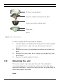
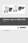
3.2
Installation | en
13
Disassembly
The flush-mount version consists of the following parts:
Camera module and mounting base
Inner liner (with sealing ring)
Trim ring
Dome
Figure 3.1 Flush-mount
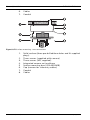
The surface-mount version consists of the following parts:
Bosch Security Systems
Installation Manual
AM18-Q0648 | v1.0 | 2013.03
14
en | Installation
FLEXIDOME 5000 AN
Surface mounting box
Camera module and mounting base
Inner liner (with sealing ring)
Trim ring
Dome
Figure 3.2 Surface-mount
To disassemble the unit proceed as follows:
1.
Use the special screwdriver bit to loosen the three tamperresistant screws in the trim ring (the screws remain in
place).
2.
Remove the trim ring and dome by pulling them from the
base.
3.
Remove the inner liner (with sealing ring) by pulling it off
4.
Remove the pink protective foam.
of the base.
3.3
Mounting the unit
There are several ways to mount the unit. The method of
mounting depends on the type of surface and whether other
mounting hardware, such as an electrical box, a surface box or
other accessories are used.
Note:
AM18-Q0648 | v1.0 | 2013.03
Installation Manual
Bosch Security Systems
FLEXIDOME 5000 AN
Installation | en
15
If the unit is to be surface mounted, then use the Surface Mount
Box (SMB). The SMB is sold as a separate item (VDA-455SMB)
or is included with the unit with the surface mount option.
Other mounting accessories are also sold separately.
3.3.1
Mounting tips
–
Use the mounting hole template to assist in marking the
correct position for the camera to be mounted.
–
Refer to the dimensions on the mounting hole template to
find the exact position of the screw holes and the entry
hole for the cables.
–
Partially screw in two screws for the keyholes and use
them to temporarily hang the camera while the
connections are made.
3.3.2
Flush mounting
Figure?3.3?Flush mounting - hollow surface
1.
Solid surface (pre-drill three 8mm holes and fit supplied
2.
3.
4.
plugs)
Three screws (supplied with camera)
Integrated camera unit and base
Cables
Bosch Security Systems
Installation Manual
AM18-Q0648 | v1.0 | 2013.03
16
en | Installation
FLEXIDOME 5000 AN
Figure?3.4?Flush mounting - electrical box (4S)
1.
2.
3.
3.3.3
Two screws (not supplied)
Integrated camera unit and base
4S electrical box
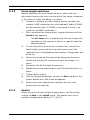
Surface mounting
When using the surface mounting box:
–
With a side connection, remove the cap covering the side
entrance.
With a rear connection, leave the cap in place.
–
Attach the conduit to the mounting box.
–
Release the two clips at the bottom of the watertight
connection compartment to remove it from the mounting
box.
–
Open the cover of the watertight compartment in the
mounting box by releasing the five clips.
–
Run the power and video cables through separate rubber
–
Run the cable from the camera into the watertight
–
Make the connection inside the watertight compartment
grommets into the watertight compartment.
compartment through the supplied grommet.
and clip on the cover to seal it.
AM18-Q0648 | v1.0 | 2013.03
Installation Manual
Bosch Security Systems
FLEXIDOME 5000 AN
Figure 3.5
Installation | en
17
Surface mounting box VDA-455SMB
Note:
To ensure a watertight cable entry, use round cables of
between 5 and 6 mm (0.2 - 0.24 inches) for power and video
connection.
Note:
Use some silicon spray on the cable to help slide the grommets
onto it.
Figure?3.6?Surface mounting - side connection
1.
Solid surface (pre-drill three 8mm holes and fit supplied
2.
3.
4.
5.
plugs)
Three screws (supplied with camera)
Three screws (M5, supplied)
Integrated camera unit and base
Surface mounting box (VDA-455SMB)
Bosch Security Systems
Installation Manual
AM18-Q0648 | v1.0 | 2013.03
18
en | Installation
6.
7.
FLEXIDOME 5000 AN
Cables
Conduit
Figure?3.7?Surface mounting - rear connection
1.
Solid surface (three pre-drilled 8mm holes and fit supplied
2.
3.
4.
5
6.
7.
8.
plugs)
Three screws (supplied with camera)
Three screws (M5, supplied)
Integrated camera unit and base
Surface mounting box (VDA-455SMB)
Cap (remove for side-entry cables)
Conduit
Cables
AM18-Q0648 | v1.0 | 2013.03
Installation Manual
Bosch Security Systems
FLEXIDOME 5000 AN
Connection and set-up | en
4
Connection and set-up
4.1
Power and video connections
19
The wiring harness has a BNC connector to accept the video
coax cable (with male BNC connector) and two stripped low
voltage power wires for connection to a power connector. A
UTP adapter (VDA-455UTP) is available as an optional accessory
to allow a UTP video cable to be connected to the BNC
connector.
The easiest way to connect the cables is as follows:
1.
Bring the building connections through the surface cable
hole so that they hang clear.
2.
Partially insert two screws into the pre-drilled holes (or
adapter plate).
3.
Using one of the keyholes, hang the mounting base of the
camera module on one screw temporarily; tilt the base
slightly to gain access to the cable connections.
4.
Connect the BNC connector of the camera module to the
video coax cable.
5.
Connect the stripped power wires (red +, brown –) to the
power supply connector.
Note
For a DC supply the polarity is important. Incorrect polarity
does not damage the camera but it will not switch on.
6.
In damp environments ensure that the connections are
sealed. (The surface mounting box and the other mounting
accessories have a sealed compartment for this purpose.)
7.
Push the connections back through the surface cable hole.
8.
Secure the mounting base of the camera module to the
surface with three screws.
Bosch Security Systems
Installation Manual
AM18-Q0648 | v1.0 | 2013.03
20
en | Connection and set-up
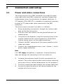
4.2
4.2.1
FLEXIDOME 5000 AN
Setting up the camera
Camera positioning
CAUTION!
The Heater will be hot when in operation - Do not touch.Always
switch the heater off when working on the camera, refer to
Section 4.2.4 Heater, page 23 and Section 5.6.4 Connections
submenu, page 41.
To assist in setting up the camera, connect a monitor to the
miniature 2.5 mm jack socket (2). This socket provides a
composite video signal (with sync). An optional cable (code
number S1460) is available for making this connection. When
the S1460 cable is attached, there is no video available on the
BNC connector to avoid interference.
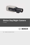
A
C
B
Figure 4.1
1.
2.
Camera parts
Heater
Monitor jack socket
AM18-Q0648 | v1.0 | 2013.03
Installation Manual
Bosch Security Systems
FLEXIDOME 5000 AN
3.
4.
5.
6.
A.
B.
C.
Connection and set-up | en
21
Thumbwheels
Navigation buttons (5)
Focal length
Focus
Pan-axis rotation
Tilt-axis rotation
Twist-axis rotation
The physical default position of the camera is that the top of
the image corresponds to the indication TOP.
CAUTION!
CCD image sensors are highly sensitive and require special care
for proper performance and extended lifetime. Do not expose
them to direct sunlight or bright spotlights in operating and
non-operating conditions. Avoid bright lights in the field of view
of the camera.
The camera module position can be adjusted along three axes.
When adjusting the camera position, ensure that the picture
display on the monitor is level. Set the camera to the desired
position by performing the following steps:
–
For horizontal adjustment along the pan axis (A), rotate the
camera module in the base. Do not rotate more than 360°.
–
To obtain a horizontal horizon (for tilted ceilings or
sidewall mounting), rotate the base of the lens along the
twist axis (C) to align the picture shown on the monitor.
Do not rotate more than 340°.
–
For vertical adjustment along the tilt axis (B), loosen
thumbwheels, position camera, then gently tighten
thumbwheels to secure camera. Do not rotate more than
90°.
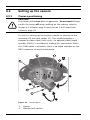
4.2.2
Menu navigation
Five keys, located on the side panel, are used for navigating
through the menu system.
Bosch Security Systems
Installation Manual
AM18-Q0648 | v1.0 | 2013.03
22
en | Connection and set-up
FLEXIDOME 5000 AN
Up key
Menu/Select key (center)
Right key
Figure 4.2
–
Navigation
Down key
Left key
Press the menu/select (center) key to access the menus or
to move to the next or previous menu.
–
Press the menu/select key for approximately 2 seconds to
open the Install menu.
–
Use the up or down keys to scroll through a menu.
–
Use the left or right keys to move through options or to set
parameters.
–
When in a menu, quickly double-press the menu/select key
to restore the selected item to its factory default.
–
To close all menus at once from any menu, select the Exit
item and hold down the menu/select key until the menu
display disappears.
AM18-Q0648 | v1.0 | 2013.03
Installation Manual
Bosch Security Systems
FLEXIDOME 5000 AN
4.2.3
Connection and set-up | en
23
Focal length and focus
Before adjusting the focal length or focus, place the lens
adjustment cap on the lens to ensure that the image sharpness
is the same as when the dome is in place.
1.
Connect a monitor or other display device to either the
camera’s BNC connector or to the optional cable (S1460)
on the monitor jack. (If S1460 is connected, there is no
signal on the BNC connector.)
2.
Press and hold the menu/select (center) button until the
Install menu appears.
–
The Set focus item is highlighted. Do not change this
selection as the camera is now in a special mode for
adjusting focus.
3.
To set the field of view of the varifocal lens, loosen the
focal length screw and turn the mechanism until the
required view is displayed on the monitor. (Image goes out
of focus.)
4.
Focus the image on the monitor by loosening the focus
screw and turning the mechanism until the image is in
focus.
5.
6.
Re-adjust the focal length if necessary.
Repeat these two adjustments until the desired view is in
focus.
7.
8.
Tighten both screws.
Use the navigation buttons to move to Exit and press the
center button until the menu disappears.
9.
Remove the lens adjustment cap from the lens and
disconnect the monitor.
4.2.4
Heater
When using the camera at low temperatures, set the heater
setting to Auto in the Install menu. The heater turns on at
ambient temperatures below 0°C (+32°F).
Bosch Security Systems
Installation Manual
AM18-Q0648 | v1.0 | 2013.03
24
en | Connection and set-up
4.2.5
FLEXIDOME 5000 AN
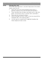
Closing the unit
When the camera position is set and all adjustments have been
made, close the unit.
1.
Place the inner liner (with attached sealing ring) in
2.
Place the dome onto the base and rotate until it clips into
position, aligning its fin with the bracket on the base.
place. (If necessary clean its surface with a soft cloth.)
3.
Place the trim ring over the dome.
4.
Align the tamper-resistant screws in the trim ring with the
threaded ends in the mounting base.
5.
Use the special screwdriver bit supplied to tighten the
three tamper-resistant screws.
AM18-Q0648 | v1.0 | 2013.03
Installation Manual
Bosch Security Systems
FLEXIDOME 5000 AN
5
Configuration | en
25
Configuration
The camera normally provides an optimal picture without the
need for further adjustments. Advanced set-up options are
available in a menu system for getting the best results under
special circumstances.
The camera implements your changes immediately so that
before and after settings are easily compared.
5.1
5.1.1
Menus
Top level menus
There are two upper level menus: a Main menu and an Install
menu. The menus have functions that can be selected directly
or submenus for more detailed set-up.
–
To access the Main menu, press the menu/select button
(center) for less than 1 second. The Main menu appears on
the monitor. The Main menu allows you to select and setup the picture enhancement functions. If you are not happy
with your changes, you can always recall the default values
for the mode.
–
The camera also has an Install menu in which the
installation settings can be set. To access the Install menu,
press the menu/select button (center) for longer than 2
seconds.
Bosch Security Systems
Installation Manual
AM18-Q0648 | v1.0 | 2013.03
26
en | Configuration
5.1.2
FLEXIDOME 5000 AN
Menu navigation
Five keys are used for navigating through menu system.
Up button
Menu/Select button (center)
Right button
Down button
Left button
–
Use the up or down keys to scroll through a menu.
–
Use the left or right keys to move through options or to set
parameters.
–
When in a menu, quickly double-press the menu/select key
to restore the selected item to its factory default.
–
To close all menus at once hold down the menu/select key
until the menu display disappears or continually select the
Exit item.
Some menus automatically close after about two minutes; other
menus have to be closed manually.
AM18-Q0648 | v1.0 | 2013.03
Installation Manual
Bosch Security Systems
FLEXIDOME 5000 AN
5.2
Configuration | en
27
Pre-defined modes
There are six pre-defined modes with settings to make
configuration easier. You can select one of the six pre-defined
modes in the Install/Mode submenu. The modes are defined as
follows;
1.
24-hour
Default installation mode to provide stable pictures over a
24-hour period. These settings are optimized for out-ofthe-box installation.
2.
Traffic
Capture high-speed objects using default shutter in
variable lighting conditions.
3.
Low light
Provide extra enhancement, such as AGC and SensUp to
make usable pictures in low-light conditions.
4.
Smart BLC
Settings optimized to capture details in high contrast and
extremely bright-dark conditions.
5.
Low noise
Enhancements are set to reduce picture noise. Useful for
conditional refresh DVR and IP storage systems because
reducing noise reduces the amount of storage required.
6.
Vibrant
This mode has enhanced contrast, sharpness and
saturation.
Bosch Security Systems
Installation Manual
AM18-Q0648 | v1.0 | 2013.03
28
en | Configuration
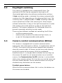
5.3
FLEXIDOME 5000 AN
Day/Night switching
The camera is equipped with a motorized IR filter. The
mechanical IR filter can be removed in low-light or IR
illuminated applications by software configuration settings.
If Auto switching mode is selected, the camera automatically
switches the filter depending on the observed light level. The
switching level is programmable. In Auto switching mode the
camera prioritizes motion (the camera gives sharp images
without motion blur as long as the light level permits) or color
(the camera gives color pictures as long as the light level
permits). The camera recognizes IR illuminated scenes to
prevent unwanted switching to color mode.
There are four different methods of controlling the IR filter:
5.4
–
via Bilinx communication,
–
automatically, based on the observed light levels, or
–
as part of the programmable mode profile.
Camera control communication (Bilinx)
This camera is equipped with a coaxial communications
transceiver (also referred to as Bilinx). In combination with VPCFGSFT, the camera setting can be changed from any point
along the coaxial cable. All menus can be accessed remotely
giving full control of the camera. With this method of
communication it is also possible to disable the local keys on
the camera.To avoid loss of communication on an installed
camera, the Communication On/Off selection is not available
while using remote control. This function can only be accessed
with the camera buttons. Bilinx communications can only be
disabled using the buttons on the camera.
Disabled camera buttons
When the Bilinx communications link is active, the buttons on
the camera are disabled.
AM18-Q0648 | v1.0 | 2013.03
Installation Manual
Bosch Security Systems
FLEXIDOME 5000 AN
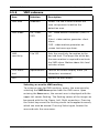
5.5
Configuration | en
29
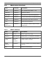
Main menu structure
Item
Selection
Description
Mode
Submenu
Sets up operating modes 1 to 6
Exposure
Submenu
Exposure control
Day/Night
Submenu
Day/Night for color/mono operation
Enhance
Submenu
Picture enhancement and performance
Color
Submenu
White balance and color rendition
VMD
Submenu
Video motion detection
Image
Submenu
Sets up digital zoom or digital image
Adjustment
5.5.1
stabilization
Mode submenu
Item
Selection
Description
Mode
1 to 6
Selects operating mode.
Mode ID
Alphanumeric
Mode name (11 characters maximum)
Copy active
Available
Copies current mode settings to the
mode
mode
mode number selected.
numbers
Mode
Submenu
Restores camera to the factory default
Defaults
settings.
EXIT
Returns to main menu.
Bosch Security Systems
Installation Manual
AM18-Q0648 | v1.0 | 2013.03
30
en | Configuration
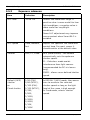
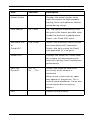
5.5.2
FLEXIDOME 5000 AN
Exposure submenu
Item
Selection
Description
ALC level
-15 to +15
Selects the video level range. A
positive value is more useful for lowlight conditions; a negative value is
more useful for very bright
conditions.
Some ALC adjustment may improve
scene content when Smart BLC is
enabled.
ALC speed
Slow, medium,
Adjusts the speed of the video level
fast
control loop. For most scenes it
should remain at the default value.
Shutter
AES, FL, Fixed
AES (auto-shutter) - the camera
automatically sets the optimum
shutter speed.
FL - flickerless mode avoids
interference from light sources
(recommended for DC-iris lenses
only).
FIXED - allows a user defined shutter
speed.
Default (AES)
1/50 (PAL)
In DEFAULT (AES) mode, the camera
shutter
1/60 (NTSC),
tries to maintain the selected
or
1/100 (PAL)
shutter speed as long as the light
Fixed shutter
1/120 (NTSC),
level of the scene is high enough.
1/250,
In Fixed mode, selects shutter
1/500,
speed.
1/1000,
1/2000,
1/4000,
1/10K,
1/100K
AM18-Q0648 | v1.0 | 2013.03
Installation Manual
Bosch Security Systems
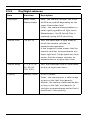
FLEXIDOME 5000 AN
Item
Configuration | en
Selection
Actual shutter
31
Description
Displays the actual shutter value
from the camera to help compare
lighting levels and optimum shutter
speed during set-up.
Gain control
On, Fixed
On - the camera automatically sets
the gain to the lowest possible value
needed to maintain a good picture.
Fixed - sets Fixed AGC value.
Maximum AGC
0 to 40 dB
Selects the maximum value the gain
or
can have during AGC operation.
Fixed AGC
Selects the gain setting for Fixed
gain operation (0 is no gain).
Actual AGC
Displays the actual AGC value from
the camera to help compare gain
level with lighting levels and picture
performance.
Sens Up
Off, 2x,
Selects the factor by which the
Dynamic
3x, …, 10x
sensitivity of the camera is
increased.
When active, some noise or spots
may appear in the picture. This is
normal camera behavior. It may also
cause motion blur on moving
objects.
EXIT
Bosch Security Systems
Returns to main menu.
Installation Manual
AM18-Q0648 | v1.0 | 2013.03
32
en | Configuration
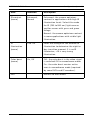
5.5.3
FLEXIDOME 5000 AN
Day/Night submenu
Item
Selection
Description
Day/Night
Auto, Color,
Auto - the camera switches the IR cut-
Monochrome
off filter on and off depending on the
scene illumination level.
Color - the camera always produces a
color signal regardless of light levels.
Monochrome - the IR cut-off filter is
removed, giving full IR sensitivity.
Switch level
-15 to +15
Sets the video level in Auto mode at
which the camera switches to
monochrome operation.
A low (negative) value means that the
camera switches to monochrome at a
lower light level. A high (positive) value
means that the camera switches to
monochrome at a higher light level.
Switch delay
1, 2, 3, 5, 10,
Sets the evaluation time in Auto mode
20, 30, 60,
for day to night transitions.
120, 240 s
Priority
Motion, Color
In AUTO mode:
Color - the camera gives a color image
as long as the light level permits.
Motion - the camera avoids motion blur
as long as the light level permits (it
switches to monochrome earlier than it
would with Color priority).
AM18-Q0648 | v1.0 | 2013.03
Installation Manual
Bosch Security Systems
FLEXIDOME 5000 AN
Configuration | en
Item
Selection
Description
IR contrast
Enhanced,
Enhanced - the camera optimizes
(mono)
Normal
contrast in applications with high IR
33
illumination levels. Select this mode
for IR (730 to 940 nm) light sources
and for scenes with grass and green
foliage.
Normal - the camera optimizes contrast
in mono applications with visible light
illumination.
IR
0 to +15
Enter the strength of the external IR
illumination
illumination to determine the night to
(mono)
day transition moment. 0 is no IR
illuminator; +15 is very strong
illumination.
Color burst
(mono)
On, Off
Off - the color burst in the video signal
is switched Off in monochrome mode.
On - the color burst remains active
even in monochrome mode (required
by some DVRs and IP encoders).
EXIT
Bosch Security Systems
Returns to main menu.
Installation Manual
AM18-Q0648 | v1.0 | 2013.03
34
en | Configuration
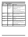
5.5.4
FLEXIDOME 5000 AN
Enhance / Dynamic Engine submenu
Item
Selection
Description
Dynamic
Off,
Off: - turns off all automatic scene
Engine
XF DYNAMIC,
detail and enhancements (only
HDR,
recommended for testing).
Smart BLC
XF DYNAMIC: - extra internal
processing is enabled for enhancing
the visibilty.
HDR: - adds dual sensor exposure to
the XF DYNAMIC features. In harsh
lighting conditions, pixels from each
exposure are mixed to give a more
detailed image.
Smart BLC: - BLC window and
weighting factor are automatically
defined. Camera dynamically adjusts
these for changing light conditions.
Contrast
Low,
Increases the contrast at medium
Enhancement
Medium,
brightness levels.
High
Select Low for high contrast scenes.
Select High for low contrast scenes
(e.g. fog).
Sharpness
-15 to +15
Adjusts the sharpness of the picture. 0
corresponds to the default position.
A low (negative) value makes the
picture less sharp. Increasing
sharpness brings out more detail.
Extra sharpness can enhance the
details of license plates, facial features
and the edges of certain surfaces.
AM18-Q0648 | v1.0 | 2013.03
Installation Manual
Bosch Security Systems
FLEXIDOME 5000 AN
Item
3D-NR
Configuration | en
Selection
Description
35
Off,
Automatically reduces the noise in the
Low,
picture.
Medium,
This may cause some motion blur on
High
exceptionally fast moving objects
immediately in front of the camera.
This can be corrected by widening the
field of view or lowering the selection
value.
2D-NR
Off,
Automatically reduces the noise in the
Low,
picture.
Medium,
A high selection may cause blur.
High
A lower selection improves sharpness
at the cost of more noise
Peak White
Invert
On, Off
Use Peak White Invert to reduce glare
from the CRT/LCD display.
Use in ANPR/LPR applications to
reduce headlight glare.
(Test on-site to ensure that it does
benefit the application and is not
distracting for operators of the security
system.)
EXIT
Bosch Security Systems
Returns to main menu.
Installation Manual
AM18-Q0648 | v1.0 | 2013.03
36
en | Configuration
5.5.5
FLEXIDOME 5000 AN
Color submenu
Item
Selection
Description
White balance
ATW indoor,
ATW - Auto tracking white balance
ATW Outdoor,
allows the camera to constantly
ATW hold,
adjust for optimal color
Manual
reproduction.
ATW hold - Puts the ATW on hold and
saves the color settings.
Manual - the Red and Blue gain can
be manually set to a desired position.
Speed
Fast,
Adjusts the speed of the white
Medium,
balance control loop.
Slow
Red gain
-50 to +50
Manual and ATW hold - adjusts the
Red gain.
Blue gain
-50 to +50
Manual and ATW hold - adjusts the
Blue gain.
Saturation
-15 to +5
Adjusts the color saturation. -15
gives a monochrome image; 0 gives
the default saturation; +15 gives the
most saturation.
EXIT
AM18-Q0648 | v1.0 | 2013.03
Returns to main menu.
Installation Manual
Bosch Security Systems
FLEXIDOME 5000 AN
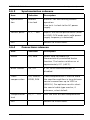
5.5.6
Configuration | en
37
VMD submenu
Item
Selection
Description
VMD area
Submenu
Select 1 of the 4 areas to enter the
area set-up menu to define the
detection area.
VMD mode
Off, Silent,
Off - Video Motion Detection (VMD) is
OSD
off.
Silent - video motion generates silent
alarm.
OSD - video motion generates onscreen text message alarm.
VMD
0 to 127
Sets the sensitivity for motion to the
sensitivity
desired level. The longer the white bar,
the more motion is required to acitvate
the VMD alarm. Motion above this level
activates alarm.
OSD alarm
Alphanumeric
Text for on-screen display alarm (16
text
characters maximum).
EXIT
Returns to main menu.
Selecting an area for VMD masking
To set-up an area for VMD masking, access the area menu by
selecting the VMD Area option from the VMD menu. Upon
entering the Area menu, the current area is displayed with the
upper left corner flashing. The flashing corner of the image can
be moved with the Up, Down, Left, Right arrow keys. Pressing
the Select key moves the flashing cursor to the opposite corner,
which can now be moved. Pressing Select again freezes the
area and exits the area menu.
Bosch Security Systems
Installation Manual
AM18-Q0648 | v1.0 | 2013.03
38
en | Configuration
5.5.7
FLEXIDOME 5000 AN
Image Adjustment submenu
Item
Selection
Description
Digital Zoom
x1, x2, x4, x8,
Select the zoom factor
x16
DIS
Off, On
EXIT
AM18-Q0648 | v1.0 | 2013.03
Select On to stabilize the image.
Returns to main menu.
Installation Manual
Bosch Security Systems
FLEXIDOME 5000 AN
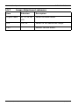
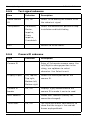
5.6
Configuration | en
39
Install menu structure
Item
Selection
Description
Language
Submenu
Select on-screen display (OSD)
language
Lens Wizard
Submenu
Select to optimize the focus point.
Synchroniza-
Submenu
Sets synchronization parameters
Connections
Submenu
Connection parameters
Test signals
Submenu
Test patterns and texts
Camera ID
Submenu
Select to access ID submenu
Privacy
Submenu
Sets up a masking area
Flip
Submenu
Selects flip submenu
Default ALL
Submenu
Returns all settings for all modes to
tion
masking
factory defaults
Bosch Security Systems
Installation Manual
AM18-Q0648 | v1.0 | 2013.03
40
en | Configuration
5.6.1
FLEXIDOME 5000 AN
Language submenu
Item
Selection
Description
Language
English
Displays the menus on the OSD in the
Spanish
chosen language.
French
German
Portuguese
Russian
Simplified
Chinese
EXIT
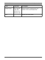
5.6.2
Returns to Install menu.
Lens Wizard submenu
Item
Selection
Set focus now
Description
Select to fully open the iris. Follow the
instructions for adjusting the focus for
the lens.
After focusing the object of interest
remains in focus under bright and low
light conditions.
EXIT
AM18-Q0648 | v1.0 | 2013.03
Returns to Install menu.
Installation Manual
Bosch Security Systems
FLEXIDOME 5000 AN
5.6.3
Configuration | en
41
Synchronization submenu
Item
Selection
Description
Synchroniza-
Internal
Internal - for free running camera
tion
Line lock
operation.
Line lock - to lock to the AC power
supply
Vertical phase
0, 1, … 359
Adjusts the vertical phase offset (when
in LINE LOCK mode and a valid power
supply frequency is detected).
EXIT
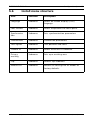
5.6.4
Returns to Install menu.
Connections submenu
Item
Selection
Description
Heater
Off, Auto
Select Auto to enable the
thermostatically controlled heater
function. The heater switches on at
approximately 0°C (+32°F).
Bilinx Comms.
On, Off
If Off, Bilinx communications is
disabled.
Cable
Off, Default,
Cable compensation is used to avoid
compensation
RG59, RG6
the need for amplifiers in long distance
coaxial connections up to 1000 m
(3000 ft). For optimum results select
the coaxial cable type used or, if
unknown, select default.
Compensation
0,1,2 . . .+15
Sets the level of cable compensation
level
EXIT
Bosch Security Systems
Returns to Install menu.
Installation Manual
AM18-Q0648 | v1.0 | 2013.03
42
en | Configuration
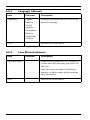
5.6.5
FLEXIDOME 5000 AN
Test signal submenu
Item
Selection
Description
Show camera
Off, On
Select On to overlay the camera ID on
ID
the video test signal.
Test pattern
Color bars,
Select the desired test pattern to help
Raster,
installation and fault-finding.
Impulse,
Cross
Impulse,
Crosshatch
EXIT
5.6.6
Returns to Install menu.
Camera ID submenu
Item
Selection
Description
Camera ID
Enter a 17-character camera name. Use
Left/Right to change position in the
string; use up/down to select
character. Use Select to exit.
Display ID pos.
Off, Top left,
Select the screen position of the
Top right,
camera ID.
Bottom left,
Bottom right
Camera ID
On, Off
Displays a grey border behind the
border
camera ID to make it easier to read.
MAC address
Shows MAC address (factory set,
cannot be changed).
Ticker bars
On, Off
The ticker bar moves continuously to
show that the image is live and not
frozen or played back.
AM18-Q0648 | v1.0 | 2013.03
Installation Manual
Bosch Security Systems
FLEXIDOME 5000 AN
Item
Mode ID pos.
Configuration | en
Selection
Description
Off, Top left,
Camera mode is displayed on the
Top right,
screen in the selected position.
43
Bottom left,
Bottom right
EXIT
Bosch Security Systems
Returns to Install menu.
Installation Manual
AM18-Q0648 | v1.0 | 2013.03
44
en | Configuration
5.6.7
FLEXIDOME 5000 AN
Privacy masking submenu
Item
Selection
Description
Mask
1 to 15
15 different areas can be masked.
Black, Grey,
Selects pattern for all masks.
Pattern
White, Noise
Active
On, Off
Turns each of the masks on or off.
Mosaic
On, Off
Turns mosaic on or off.
Window
Submenu
Select to open a window in which to
define the mask area.
Selecting an area for privacy masking
To set-up an area for privacy masking, access the area menu by
selecting the Area option from the privacy masking menu. Upon
entering the Area menu, the current area is displayed with the
upper left corner flashing. The flashing corner of the image can
be moved with the Up, Down, Left, Right arrow keys. Pressing
the Select key moves the flashing cursor to the opposite corner,
which can now be moved. Pressing Select again freezes the
area and exits the area menu.
5.6.8
Flip submenu
Item
Selection
Description
Off
Selects the flip mode.
Flip
horizontal
Vertical
Both
EXIT
AM18-Q0648 | v1.0 | 2013.03
Returns to Install menu.
Installation Manual
Bosch Security Systems
FLEXIDOME 5000 AN
5.6.9
Configuration | en
45
Defaults submenu
Item
Selection
Description
Restore All
No, Yes
Restores all settings of the six modes
to their default (factory) values. Select
YES then press the Menu/Select
button to restore all values.
When completed the message
RESTORED! is shown.
Bosch Security Systems
Installation Manual
AM18-Q0648 | v1.0 | 2013.03
46
en | Troubleshooting
FLEXIDOME 5000 AN
6
Troubleshooting
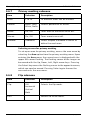
6.1
Resolving problems
The following table is intended to help you identify the causes
of malfunctions and correct them when possible.
Malfunction
Possible causes
Solution
No image
Defective camera.
Connect a local monitor
transmission to
to the camera and check
remote location.
the camera function.
Faulty cable connections. Check all cables, plugs,
contacts and
connections.
Incorrect cable
When using DC power
connections.
ensure that polarity is
correct.
No connection
The unit's configuration.
Check all configuration
established, no
parameters.
image transmission. Faulty installation.
Check all cables, plugs,
contacts and
connections.
AM18-Q0648 | v1.0 | 2013.03
Installation Manual
Bosch Security Systems
FLEXIDOME 5000 AN
6.2
Troubleshooting | en
47
Customer service
If you cannot resolve a fault, please contact your supplier or
system integrator, or contact Bosch Security Systems
Customer Service directly.
The Installer should write down all information regarding the
unit so that it can be referenced for warranty or repair. The
version numbers of the firmware and other status information
can be seen when the unit starts or by opening the Install
menu. Note down this information and the information found
on the camera label before contacting customer service.
Bosch Security Systems
Installation Manual
AM18-Q0648 | v1.0 | 2013.03
48
en | Maintenance
FLEXIDOME 5000 AN
7
Maintenance
7.1
Repairs
CAUTION!
Never open the casing of the camera. The unit does not contain
any user serviceable parts. Ensure that all maintenance or
repair work is performed only by qualified personnel (electrical
engineering or network technology specialists). If in doubt,
contact your dealer's technical service center.
7.1.1
Transfer and disposal
The camera should only be passed-on together with this
installation guide. The unit contains environmentally hazardous
materials that must be disposed of according to law. Defective
or superfluous devices and parts should be disposed of
professionally or taken to your local collection point for
hazardous materials.
AM18-Q0648 | v1.0 | 2013.03
Installation Manual
Bosch Security Systems
FLEXIDOME 5000 AN
Technical Data | en
8
Technical Data
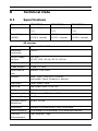
8.1
Specifications
Type number
Lens
VDN-5085-3
VDN-5085-9
VDN-5085-A
2.8 to 10.5 mm
9 to 22 mm
18 to 55 mm
F1.2
F1.4
F1.5
Sensitivity
<0.06 lx
<0.08 lx
<0.09 lx
(30IRE)
<0.03 lx (mono)
<0.04 lx (mono)
<0.05 lx (mono)
49
All versions
Imager
1/3-inch 960H CCD sensor
Maximum
720TVL
resolution
Rated supply
+12 VDC
voltage
24 VAC (PAL: 50 Hz; NTSC: 60 Hz)
SNR
> 54 dB
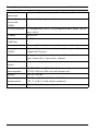
Video output
1 Vpp, 75 Ohm
Synchroniza-
Internal, Line Lock
tion
Shutter
Auto (1/60 [1/50] to 1/100000)
Selectable, fixed, flickerless, default
Day/Night
Color, Mono, Auto
Sens Up
Adjustable from Off to 10x
AGC
AGC On or Off (0 - 40 dB) selectable
Dynamic engine
XF Dynamic, HDR, Smart BLC
Dynamic Range
94 dB
Dynamic Noise
3D-NR, 2D-NR
Reduction
Sharpness
Sharpness enhancement level selectable
White Balance
ATW indoor, ATW outdoor, ATW hold and manual
Contrast
Low, Medium, High
Enhancement
Bosch Security Systems
Installation Manual
AM18-Q0648 | v1.0 | 2013.03
50
en | Technical Data
Test pattern
FLEXIDOME 5000 AN
Color bar, Raster, Impulse, Cross Impulse, Cross hatch
generator
Video Motion
4 areas, fully programmable
Detection
(VMD)
Privacy Masking 15 independent areas, fully programmable; black, white,
grey, noise
E-zoom
Up to 16x
Digital Image
On/Off
Stabilizer
Communication
Two-way Bilinx (bi-directional)
Languages
English, Spanish, French, German, Portuguese, Russian,
(OSD)
Simplified Chinese
Modes
6 programmable (preset) modes: 24-hour, Traffic, Lowlight, Smart BLC, Low noise, Vibrant
Peak White
Suppresses highlights in scenes
Invert
Power
12 VDC 360 mA (700 mA with heater on)
consumption
24 VDC 330 mA (650 mA with heater on)
Weight
750 g (1.65 lb)
Operating
-30 °C to +55 °C (-22 °F to +131 °F)
temperature
(-50 °C [-58 °F] with heater enabled)
Controls
OSD with softkey operation
AM18-Q0648 | v1.0 | 2013.03
Installation Manual
Bosch Security Systems
FLEXIDOME 5000 AN
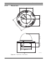
8.1.1
Technical Data | en
51
Dimensions
57.6 (2.27)
12
66.5 (2.62)
33.3 (1.31)
57.6 (2.27)
1
39.5 (1.56)
85 (3.35)
)
77
.
(4
95 (3.7)
158 (6.22)
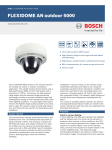
Figure 8.1
Bosch Security Systems
mm (in)
Dimensions - Flush-mount
Installation Manual
AM18-Q0648 | v1.0 | 2013.03
52
en | Technical Data
FLEXIDOME 5000 AN
53.3 (2.1)
35 (1.38)
30.8 (1.21)
53.3 (2.1)
4.77)
130.5 (5.14)
121 (
158 (6.22)
Figure 8.2
AM18-Q0648 | v1.0 | 2013.03
mm (in)
Dimensions - Surface-mount
Installation Manual
Bosch Security Systems
FLEXIDOME 5000 AN
8.1.2
Technical Data | en
53
Accessories
–
BNC to UTP transceiver
–
Surface Mount Box (SMB)
–
Pendant wall mount
–
Pendant ceiling mount
–
Corner mount
–
Bilinx communication interface box and software
Contact a Bosch representative in your area for the latest
available accessories or visit our website at
www.boschsecurity.com
Bosch Security Systems
Installation Manual
AM18-Q0648 | v1.0 | 2013.03
54
en | Technical Data
AM18-Q0648 | v1.0 | 2013.03
FLEXIDOME 5000 AN
Installation Manual
Bosch Security Systems
Bosch Security Systems
www.boschsecurity.com
© Bosch Security Systems, 2013