1
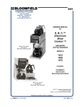
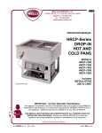
600
USER'S GUIDE for
BLOOMFIELD TRADITIONAL DISPLACEMENT-TYPE
COFFEE BREWERS
Includes:
Installation
Checkout
Theory of Operation
Troubleshooting
p/n 86772 Rev. (-)
M600 102203 cps
INTRODUCTION
The technical content of
this manual represents
current production models
as of October, 2003.
Data, specifications and
materials, and model
number designations are
subject to change at any
time without notice.
This manual is intended for use by qualified service personnel.
Bloomfield coffee brewers are intended exclusively for commercial use
and are designed expressly to brew beverage products for human
consumption. No other use is recommended or authorized by the
manufacturer or its agents.
Except as noted, this piece of equipment is made in the USA and has
American sizes on hardware. All metric conversions are approximate.
This is a general guide for this class of brewers. Examples in this
manual are provided to illustrate concepts only. Your specific application
may vary. Consult the Owner's Manual for your specific equipment.
SAFETY WARNINGS AND PRECAUTIONS
WARNING: ELECTRIC SHOCK HAZARD
All servicing requiring access to non-insulated components must be performed by qualified
service personnel. Do not open any access panels which require the use of tools unless you
are qualified to do so. Failure to heed this warning can result in electrical shock. Electrical
shock can cause death or serious Injury.
WARNING: INJURY HAZARD
All installation procedures must be performed by qualified personnel with full knowledge of all
applicable electrical and plumbing codes. Failure could result in personal injury and
property damage.
WARNING: ELECTRIC SHOCK HAZARD
Brewer must be properly grounded to prevent possible shock hazard. DO NOT assume a
plumbing line will provide such a ground.
WARNING: BURN HAZARD
This appliance dispenses very hot liquid. Serious bodily injury from scalding can occur from
contact with dispensed liquids.
CAUTION: SHOCK HAZARD
Always disconnect the brewer fro electrical power before servicing or cleaning.
DO NOT submerge electrical equipment in water.
Avoid contaminating electrical components with water when cleaning the cabinet surfaces.
CAUTION: BURN HAZARD
Exposed surfaces of the appliance, brew chamber and airpot ,decanter or thermal server may
be HOT to the touch, and can cause serious burns.
CAUTION: ELECTRICAL DAMAGE
DO NOT plug in or energize this appliance until all Installation Instructions are read and
followed. Damage to the brewer will occur if these instructions are not followed.
xi
TABLE OF CONTENTS
INSTALLATION PROCEDURES …………………………………….. 2
BREWER OVERALL CHECKOUT ……………………………………. 4
BREWING COFFEE …………………………………………………… 5
CLEANING INSTRUCTIONS …………………………………………. 6
THEORY OF OPERATION
WATER FLOW ………………………………………...………….… 7
HOT WATER FAUCET …………………………………………….. 8
BREW WATER TEMPERATURE CONTROL …………………… 9
TROUBLESHOOTING GUIDE
QUICK GUIDE ………………………………………………………. 10
BREW WATER SYSTEM - AUTOMATIC OPERATION .....…… 11
BREW WATER SYSTEM - POUR-OVER ……………………….. 12
FAUCET WATER SYSTEM ……………………………………….. 15
ELECTRICAL SYSTEM - BREW …………………………………. 19
ELECTRICAL SYSTEM - HEATING ……………………………… 20
ELECTRICAL SYSTEM - WARMERS ……………………………. 21
SERVICING INSTRUCTIONS
TEMPERATURE ADJUSTMENT …………………………………. 22
TIMER ADJUSTMENT ……………………………………………… 23
REMOVE TANK ……………………………………………………. 23
REPLACE THERMOSTAT ………………………………………… 23
REPLACE HEATING ELEMENT ………………………………….. 23
REPLACE FILL SOLENOID ……………………………………….. 24
CLEAN SOLENOID SCREEN ……………………………………. 24
REPLACE TIMER ASSEMBLY …………………………………… 25
REPLACE HOT WATER COIL …………………………………… 25
REPAIR HOT WATER FAUCET ………………………………….. 25
REPLACE "READY-TO-BREW" LIGHT OR BREW SWITCH …. 25
DELIME WATER TANK ……………………………………………. 26
1
INSTALLATION
READ THIS CAREFULLY BEFORE STARTING THE INSTALLATION
IMPORTANT:
To enable the installer to make
a quality installation and to
minimize installation time, the
following suggestions and tests
should be done before the
actual unit installation is started:
CAUTION:
ELECTRICAL
DAMAGE
DO NOT plug in or energize this
appliance until all Installation
Instructions are read and
followed. Damage to the
Brewer will occur if these
instructions are not followed.
CAUTION:
UNSTABLE
EQUIPMENT HAZARD
It is very important for safety
and for proper operation that the
brewer is level and stable when
standing in its final operating
position. Provided adjustable,
non-skid legs must be installed
at each corner of the unit.
Failure to do so will result in
movement of the brewer which
can cause personal Injury and/
or damage to brewer.
NOTE: Water supply inlet line
must meet certain minimum
criteria to insure successful
operation of the brewer.
Bloomfield recommends 1/4"
copper tubing for installation of
less than 12 feet and 3/8" for
more than 12 feet from a 1/2"
water supply line.
This general information may not apply to all models. Refer to
the owners manual and any technical data sheets for your
specific equipment for additional information.
PREPARATION
Unpack the unit. Inspect all components for completeness and
condition. Ensure that all packing materials have been removed
from the unit.
Verify that the Spray Head Gasket and Spray Disk are properly
installed.
IMPORTANT: The gasket must be installed INSIDE the brew
head cup.
Verify that an adjustable leg is installed at each corner of the
brewer, and, if provided, the rubber foot is installed on each leg.
Set Brewer in its operating location. Level the Brewer. A spirit
level should be placed on the top of the unit, at the edge, as a
guide when making level adjustments.
Level the unit from left to right and front to back by turning the
adjustable feet. Be sure all four feet touch the counter to prevent
tipping.
PLUMBER’S INSTALLATION INSTRUCTIONS
Brewer should be connected to a POTABLE WATER, COLD
WATER line. Flush water line before connecting to Brewer.
DO NOT use a saddle valve with a self-piercing tap for the water
line connection. Such a tap can become restricted by waterline
debris. For systems that must use a saddle tap, shut off the main
water supply and drill a 3/16” (minimum) tap for the saddle
connection, in order to insure an ample water supply. Remember
to flush the line prior to installing the saddle.
The brewer must be installed on a water line with average
pressure between 20 PSI and 90 PSI. If your water pressure
exceeds 90 PSI at anytime, a pressure regulator must be
installed in the water supply line to limit the pressure to not more
than 90 PSI in order to avoid damage to lines and solenoid.
A water shut-off valve should be installed on the incoming water
line in a convenient location (Use a low restriction type valve,
such as a 1/4-turn ball valve, to avoid loss of water flow thru the
valve.
The provided water line strainer must be installed in the supply
line, between the shutoff valve and inlet fitting. Note FLOW
arrow marking on strainer body.
2
INSTALLATION (continued)
NSF requires that the brewer be able to be moved for cleaning
underneath. A flex line or loops of copper tubing will satisfy this
requirement. See Figure 2 below.
NOTE: This equipment must be
installed to comply with
applicable federal, state and
local plumbing codes and
ordinances.
WARNING:
SHOCK HAZARD
Water Supply Installation
In some areas, local codes require a backflow preventer (check
valve) to be installed on the inlet water line. If a backflow
preventer is used, you must install a water hammer arrester in
the incoming line, between the backflow preventer and the
brewer inlet, as far away from the brewer as space will allow.
This will relieve the excessive back pressures that can cause
faucet leaks and solenoid malfunctions.
IMPORTANT:
Tank must be full of water before connecting brewer to electrical
power. Heating elements will be damaged if allowed to operate
without being fully submerged in water. Damage caused by
operating the brewer without water in the tank is NOT COVERED
BY WARRANTY.
ELECTRICIAN’S INSTALLATION INSTRUCTIONS
REFER TO ELECTRICAL SPECIFICATIONS provided in the
Owner's Manual, specification sheet, and on the nameplate.
Some models are equipped with a cord and plug. They require:
1. A circuit that meets or exceeds the electrical requirements
2. A properly installed and grounded receptacle configured
to match the brewer plug.
Some models are designed to be connected directly to the
electrical circuit. They require:
1. A circuit that meets or exceeds the electrical requirements
2. Conduit and fittings that meet applicable electrical codes.
3. The ground lug of the brewer must be connected to a suitable
electrical ground.
3
Brewer must be properly
grounded to prevent possible
shock hazard. DO NOT
assume a plumbing line will
provide such a ground.
Electrical shock will cause death
or serious injury.
IMPORTANT:
Supply power must match
nameplate for voltage and
phase. Connecting to the
wrong voltage will damage the
brewer or result in decreased
performance. Such damage is
not covered by warranty.
IMPORTANT:
The ground prong of the plug is
part of a system designed to
protect you from electrical shock
in the event of internal damage.
Never cut off the ground prong
nor twist a blade to fit an
existing receptacle. Contact a
licensed electrician to install the
proper circuit and receptacle.
GROUND
PIN
NEMA 5-15P
PLUG
NEMA 5-15R
RECEPTACLE
Typical Plug/Receptacle
Configuration
BREWER OVERALL CHECK-OUT
CAUTION:
SHOCK HAZARD
Always disconnect the brewer
fro electrical power before
servicing or cleaning.
CAUTION:
BURN HAZARD
Brew water is extremely hot.
Exposed surfaces of the brew
chamber and airpot ,decanter
or thermal server may be HOT
to the touch, and can cause
serious burns.
BREWER CHECK-OUT
These checks should be performed:
•
•
•
When the brewer is installed
During any service call on the brewer
During any subsequent follow-up call
IMPORTANT:
Tank must be full of water before pressing POWER key "ON".
Heating elements will be damaged if allowed to operate without
being fully submerged in water.
Damage caused by operating the brewer without water in the tank
is NOT COVERED BY WARRANTY.
1. Clean spray disk
If any problems are
encountered with the operation
of this brewer, please refer to
the TROUBLESHOOTING
GUIDE, beginning on page 10.
2. Check spray disk gasket. Be sure it is installed inside of the
brew head cup.
IMPORTANT:
When operating the brewer for
the first time, the tank must be
filled with water BEFORE
connecting to electric power.
Place an empty container under
the brew head, then pour
water into the pour-over
opening until water flows from
the brew head. When all
dripping stops, remove and
empty the container. It is now
safe to connect brewer to
electric power.
4. Check the brew temperature at the brew head:
a. Install a paper filter in the brew chamber, then install the
brew chamber under the brew head. Set an empty
container in position under the brew head.
b. Withdraw the brew chamber slightly, and insert the
temperature probe of a digital thermometer into the brew
chamber so that the tip is near the discharge hole.
Be sure the brewer is up to temperature ( "ready-to-brew"
light is on), then start a brew.
c. At this location, temperature should be near
190ºF for coffee
195ºF for tea
3. Check operation of Power Switch(es), Brew Switch and Brew
Cancel Switch.
5. Check the water delivery volume.
6. Where applicable, check operation of warmers and warmer
switches.
7. Disconnect brewer from electric power. Remove top panel and
check hoses and connections for water leaks.
8. Where applicable, check hot water faucet for operation and
leaks.
Fill Water Tank
4
BREWING COFFEE
CAUTION:
Burn Hazard
PREPARATION
Place one (1) genuine Bloomfield
paper filter in the brew chamber.
Add a pre-measured amount of
fresh coffee grounds.
Gently shake the brew chamber to
level the bed of grounds. Slide the
brew chamber into place under the
brew head.
Brew Chamber
PAPER
FILTER
BREW
CHAMBER
POUR-OVER OPERATION
BE sure “READY TO BREW” light is lit.
Place the appropriate EMPTY decanter in place under the brew
chamber.
Fill a decanter with tap water. Lift the pour-over cover and pour the
entire contents of the decanter into the pour-over opening, which
will fill the basin.
Water from the basin will displace a like amount of heated water
from the tank. The hot water will be forced into the brew head
where it will spray over the bed of grounds. Freshly brewed coffee
will begin to fill the container under the brew chamber. When the
flow and all dripping stops, the coffee is ready to serve.
Discard the contents of the brew chamber. Rinse the brew
chamber in a sink. When the ”READY TO BREW” light glows, the
brewer is ready for another brew cycle.
AUTOMATIC OPERATION
BE sure “READY TO BREW” light is lit.
Place an EMPTY decanter in place under the brew chamber.
Press the “BREW” switch. The solenoid will open for an amount of
time determined by the timer setting, admitting a measured quantity
of water into the basin.
Water from the basin will displace a like amount of heated water
from the tank. The hot water will be forced into the brew head
where it will spray over the bed of grounds. Freshly brewed coffee
will begin to fill the decanter under the brew chamber. When the
coffee flow and all dripping stops, the coffee is ready to serve.
Discard the contents of the brew chamber and rinse it in a sink.
When the ”READY TO BREW” light glows, the brewer is ready
for another brew cycle.
NOTE: Water for the hot water faucet is heated in a coil inside of
the water tank. Use of the faucet will not affect the volume of water
delivered for a brew. However, overuse of the faucet during a
brew may lower the temperature of the brew water.
5
Exposed surfaces of the
brewer, brew chamber and
decanter may be HOT to
the touch, and can cause
serious burns.
CAUTION:
Burn Hazard
To avoid splashing or overflowing hot liquids,
ALWAYS place an empty
decanter under the brew
chamber before starting
the brew cycle. Failure to
comply can cause serious
burns.
CAUTION:
Burn Hazard
After a brew cycle, brew
chamber contents are
HOT. Remove the brew
chamber and dispose of
used grounds with care.
Failure to comply can
cause serious burns.
IMPORTANT:
Before operating the
brewer for the first time,
the tank must be filled with
water BEFORE connecting
to electric power.
Place an empty decanter
under the brew head, then
pour decanters of water
into the pour-over opening
until water flows from the
brew head.
CLEANING INSTRUCTIONS
CAUTION:
PROCEDURE: Clean Coffee Brewer
BURN HAZARD
Brewing and serving
temperatures of coffee are
extremely hot.
Hot coffee will cause
serious skin burns.
PRECAUTIONS: Disconnect brewer from electric power.
Allow brewer to cool.
FREQUENCY:
Daily
TOOLS:
Mild Detergent, Clean Soft Cloth or Sponge
Bristle Brush, Bottle Brush
CAUTION:
SHOCK HAZARD
Do not submerge or immerse
brewer in water.
IMPORTANT:
DO NOT use steel wool, sharp
objects, or caustic, abrasive or
chlorinated cleansers to clean
the brewer or airpots.
1. Disconnect brewer from electric power.
Allow brewer to cool before cleaning.
2. Remove airpot.
3. Remove and empty brew chamber.
4. Remove the spray disk from the brew head (See figure 7):
Press up on the spray disk ears, then turn the disk to the left
to unlatch. Remove the gasket from inside the brew head.
5. Wipe inside of brew head and area around the brew head
with a soft clean cloth or sponge moistened with clean water.
6. Wash the spray disk in a sink using warm water and a mild
detergent. A bristle brush may be used to clear clogged
spray holes. Rinse the spray disk with clean water and allow
to air dry.
7. Wash the brew chamber in a sink using warm water and a
mild detergent. A bristle brush may be used to clean the
inside. Rinse with clean water and allow to air dry.
8. Wipe the exterior of the brewer with a soft clean cloth or
sponge moistened with clean water.
10. Reinstall the gasket INSIDE the brew head, then reinstall the
spray disk.
11. Reinstall the brew chamber.
Cleaning
12. DO NOT submerge airpots in water. Clean airpots by filling
with warm soapy water. Scrub the inside with a bottle brush.
Empty and rinse with clean water. Wipe the exterior with a
soft clean cloth or sponge moistened with clean water. Invert
and allow to air dry.
Procedure is complete
6
THEORY OF OPERATION
WATER FLOW
Typical Brew Water Delivery System
POUR-OVER FEATURE
Pouring any amount of cold water into the
pour-over opening and into the basin pan
forces an identical amount of hot water out
of the tank and through the spray head into
the brew chamber.
AUTOMATIC OPERATION
Pressing BREW button energizes the
solenoid valve, allowing water from an
external water supply to flow into the basin
pan and then into the hot water tank. This
forces an identical amount of hot water out
of the tank and through the spray head into
the brew chamber
The solenoid uses a flow control device so
that flow is consistent between 20 p.s.i. and
90 p.s.i.
Length of time the solenoid is open is
controlled by the timer.
Fig. 5 Water Flow Diagram
7
THEORY OF OPERATION (continued)
HOT WATER FAUCET
Typical Hot Water Faucet System
The faucet water coil is submerged in the hot water
tank and draws heat from the brew water.
Faucet water flows through the bypass side of the
water inlet and is not controlled by the solenoid valve.
The faucet is at supply water pressure any time the
faucet shut-off valve is OPEN.
Hot Water Faucet Flow Diagram
8
THEORY OF OPERATION (continued)
BREW WATER TEMPERATURE CONTROL
Typical Heating System Electrical Configuration
The heating elements are energized when line
power is applied to the element terminals.
Water temperature is sensed by a thermobulb
inserted into the water tank. This temperature
signal is fed to the thermostat by a capillary tube.
An increase in temperature causes an increase in
pressure in the thermobulb. This will cause the
pressure diaphragm in the thermostat to open the
line power contacts. A decrease in temperature
will similarly cause the pressure diaphragm to
close the contacts.
The setpoint (desired temperature) is adjustable
by turning the thermostat shaft. Turning the shaft
1/8 turn will change the setpoint by approximately
10ºF.
The element is protected from over-temperature
by a hi-limit thermostat, which breaks line power if
the temperature exceeds 260ºF.
The Ready-To-Brew light glows any time the
thermostat is not calling for heat.
9
Heat Control Diagram
TROUBLESHOOTING GUIDE
QUICK GUIDE
SYSTEM
The first step in troubleshooting
is to determine where to start.
A few simple checks should
quickly point to the major area
of concern.
BREW WATER - AUTOMATIC OPERATION .....……..…
BREW WATER - POUR-OVER ………………………..…..
FAUCET WATER ………………………………….………..
ELECTRICAL - BREW ……………………………….…….
ELECTRICAL - HEATING ……………………………….…
ELECTRICAL - WARMERS ………………………….….….
PAGE
10
11
12
15
19
20
21
TROUBLESHOOTING GUIDE (continued)
BREW WATER SYSTEM - AUTOMATIC OPERATION
11
TROUBLESHOOTING GUIDE (continued)
BREW WATER SYSTEM - AUTOMATIC OPERATION
12
TROUBLESHOOTING GUIDE (continued)
BREW WATER SYSTEM - AUTOMATIC
IMPORTANT:
To avoid overflowing the brew container, ALWAYS start
the brew with an empty container under the brew head.
13
TROUBLESHOOTING GUIDE (continued)
BREW WATER SYSTEM - AUTOMATIC OR POUR-OVER OPERATION
14
TROUBLESHOOTING GUIDE (continued)
BREW WATER SYSTEM - POUR-OVER OPERATION
15
TROUBLESHOOTING GUIDE (continued)
FAUCET WATER SYSTEM
16
TROUBLESHOOTING GUIDE (continued)
FAUCET WATER SYSTEM
17
TROUBLESHOOTING GUIDE (continued)
FAUCET WATER SYSTEM
18
TROUBLESHOOTING GUIDE (continued)
ELECTRICAL SYSTEM - BREW
CAUTION:
ELECTRIC SHOCK
HAZARD
Exposed electric circuits. Use
due caution when working
near live electric circuits.
19
TROUBLESHOOTING GUIDE (continued)
ELECTRICAL SYSTEM - HEATING
CAUTION:
ELECTRIC SHOCK
HAZARD
Exposed electric circuits. Use
due caution when working
near live electric circuits.
20
TROUBLESHOOTING GUIDE (continued)
CAUTION:
ELECTRIC SHOCK
HAZARD
Exposed electric circuits. Use
due caution when working
near live electric circuits.
21
SERVICING INSTRUCTIONS
CAUTION
Electric Shock
Hazard
These procedures involve
exposed electrical circuits.
These procedures are to be
performed by qualified
technical personnel only.
TEMPERATURE ADJUSTMENT
Unplug power cord or turn circuit breaker OFF. Remove top
panel.
Pull vent tube out of tank lid and insert a thermometer of known
accuracy in vent hole. Reconnect brewer to electrical power.
Fig. 10 Checking and Adjusting Brew Temperature
NOTE:
Optimum brewing temperature
range is 195ºF to 205ºF (90ºC
to 96ºC).
IMPORTANT:
A mechanical thermostat will
maintain temperature within
±5ºF. To prevent boiling water
in the brewer, thermostat should
be adjusted to a maximum
temperature equal to the local
boiling temperature minus 5ºF.
Place an empty decanter under brew chamber. Energize brewer
and pour one decanter (64 oz.) of cold water into pour-over
opening. When READY TO BREW light comes on, read
temperature displayed on thermometer.
Adjust thermostat by turning shaft; clockwise increases
temperature. 1/8 turn = approximately 10ºF.
Refer to Table 1 below for proper brewing temperature based on
altitude.
Table 1
Boiling Temperature by Altitude
Upon completion, remove thermometer and reinstall vent tube.
22
SERVICING INSTRUCTIONS (continued)
TIMER ADJUSTMENT
The amount of water dispensed automatically during a brew cycle
is controlled by the timer.
Place empty decanter under brew chamber. Press BREW
button. Brewer should dispense one decanter of water. To
adjust amount:
Remove brew chamber and button plug. Adjust knob on timer;
clockwise increases time. Run several cycles to check amount of
water delivered. Replace button plug.
IMPORTANT: Water pressure
must be between 20 p.s.i and
90 p.s.i. flowing pressure.
If water pressure exceeds this
value, or if water pressure
varies greatly, a pressure
regulator must be installed in
the water supply line.
REMOVE TANK LID ASSEMBLY
Unplug brewer or turn circuit breaker OFF. Turn OFF water
supply. Remove top panel. Pull vent tube and inlet elbow out of
basin pan.
Pull water inlet tube out of basin pan. Remove basin pan.
On models with faucet, disconnect inlet pipe at faucet shut-off
valve and outlet pipe at faucet.
IMPORTANT: Before setting
assembly into tank, make sure
tank lid gasket is properly
seated on flange of lid.
DO NOT OVER-TIGHTEN.
Disconnect all wiring from thermostat, hi-limit, and heating
element.
Loosen center screw on tank hold-down bracket. Remove
hold-down bracket by sliding short slotted end off of locking stud
and lifting it off. Remove cover assembly by lifting it straight up.
Reassemble in reverse order.
REPLACE THERMOSTAT
Unplug brewer or turn circuit breaker OFF. Turn OFF water
supply. Remove top panel.
Disconnect all wiring from thermostat only. Loosen and free jam
nut from pass-thru fitting securing temperature sensing bulb.
Remove two screws holding thermostat to bracket.
Lift out thermostat, sensing bulb and thermostat gasket.
Reassemble in reverse order.
REPLACE HEATING ELEMENT
Remove tank lid assembly per above.
Remove two hex nuts holding element to cover. Pull element
from mounting holes.
Reassemble in reverse order.
23
IMPORTANT: When mounting
thermostat, be sure a new seal
washer is placed below the
fitting on the capillary line.
Push sensing bulb thru tank lid
until fitting seats.
Tighten capillary lock nut only
enough to ensure no water
leakage. Excessive tightening
is not necessary.
IMPORTANT: When replacing
heating element, also replace
seal gaskets.
SERVICING INSTRUCTIONS (continued)
REPLACE SOLENOID
Symptom: Automatic brewer will not flow water; or,
automatic brewer drips continuously from brew head.
Unplug power cord or turn circuit breaker OFF. Turn OFF and
disconnect water supply from brewer inlet fitting.
Unscrew water inlet fitting from solenoid.
Remove two screws holding access door in place. Remove two
screws holding solenoid to door.
Disconnect wiring from solenoid.
Slide the 7/16" end of the wrench between the valve body and
the white ring on the extreme end of the metal hose fitting.
Pressure on the white ring toward the metal ferrule releases the
clinch ring, allowing the hose to be easily slid off of the solenoid
bypass outlet.
Transfer solenoid bracket to new solenoid.
Reinstall hose by pressing end of hose onto bypass outlet until it
is fully seated.
Reassemble in reverse order.
CLEAN SOLENOID SCREEN
Symptom: Automatic brewer will not flow water.
Unplug power cord or turn circuit breaker OFF. Turn OFF and
disconnect water supply from brewer inlet fitting.
Unscrew water inlet fitting from solenoid.
Using needle-nose pliers, withdraw strainer screen from solenoid.
Clean screen under faucet. A stiff bristle brush may be used if
necessary.
Reinsert screen in solenoid. Be careful to maintain correct
orientation. (The OPEN END of the screen goes in FIRST.)
Fig. 11
Fig. 12
Remove Faucet
Supply from Solenoid
Reassemble in reverse order.
Clean Strainer Screen
24
SERVICING INSTRUCTIONS (continued)
REPLACE TIMER ASSEMBLY
Unplug power cord or turn circuit breaker OFF.
Remove front panel. Remove knob and three screws holding
timer to bracket. Disconnect wiring to timer.
IMPORTANT: When replacing
water faucet coil, also replace
seal gaskets.
Reassemble in reverse order.
Adjust timer as described on page 13
REPLACE HOT WATER FAUCET COIL
Symptom: Brewer drips continuously from brew head, except
when faucet valve is turned OFF.
Remove tank lid assembly per above.
Remove two hex nuts hot water coil to cover. Pull coil from
mounting holes.
Reassemble in reverse order.
REPAIR HOT WATER FAUCET
Remove top panel and turn faucet valve OFF.
Unscrew aerator cap from faucet and remove handle retaining
clip. Do not let faucet body turn.
Pull bonnet assembly from faucet body.
Examine the interior of the faucet body and the surface of the
seat cup. Clean out any debris in the faucet body, using a stiff
bristle brush if necessary.
Examine the aerator. Clean any debris from the screen or flow
straightener, using a stiff bristle brush if necessary.
Reassemble in reverse order.
REPLACE BREW READY LIGHT or BREW BUTTON
Unplug power cord or turn circuit breaker OFF.
Using Switch Removal Tool (p/n 83209) or a thin screwdriver, pry
light or switch from mounting hole. Disconnect leads.
Reassemble in reverse order.
25
NOTE: Any abrasion or
roughness on the flat end of the
seat cup will require replacing
the seat cup:
Work the seat cup out of the
bonnet and off of the end of the
stem.
Install a new seat cup, making
sure the knob on the stem is
fully inserted into the pocket of
the seat cup, and the skirt of the
seat cup is fully inserted into the
bonnet.
SERVICING INSTRUCTIONS (continued)
CAUTION CHEMICAL BURN
HAZARD
Deliming chemicals are caustic.
Wear appropriate protective
gloves and goggles during this
procedure.
Never siphon deliming
chemicals or solutions by
mouth.
This operation should only be
performed by qualified and experienced service personnel.
IMPORTANT: DO NOT spill,
splash or pour water or deliming
solution into or over any internal
component other than the inside
of the water tank.
IMPORTANT: DO NOT allow
any internal components to
come into contact with the
deliming solution. Take care to
keep all internal components
dry.
NOTE: Repeat steps 4 thru 5
as required to remove all scale
and lime build-up.
PROCEDURE: Delime the Water Tank
PRECAUTIONS: Disconnect brewer from electric power.
Allow brewer to cool.
FREQUENCY:
As required (Brewer slow to heat)
TOOLS:
Deliming Solution
Protective Gloves, Goggles & Apron
Mild Detergent, Clean Soft Cloth or Sponge
Bristle Brush, Bottle Brush
Large Sink (or other appropriate work area)
1. Disconnect brewer from the electrical supply. Turn off the
water shut-off valve and disconnect the water supply line
from the brewer inlet fitting.
2. Remove the tank lid assembly as described on page 13.
3. Remove the water tank from the brewer body by lifting
straight up. Empty all water from the tank. Set the tank back
into the brewer.
4. Mix 2 quarts of deliming solution according to the
manufacturer’s directions. Carefully pour the deliming
solution into the water tank. Lower the lid assembly back
onto the tank. Allow to sit for 30 minutes, or as directed by
the manufacturer.
5. At end of soaking period, remove lid assembly from tank.
Thoroughly rinse internal components of lid assembly with
clear water. Using a stiff bristle brush, scrub the heating
element (and faucet water coil on automatic brewers) to
remove lime and calcium build-up. Rinse with clean water.
Store lid assembly in a safe location .
6. Remove the tank from the brewer and empty. Using a stiff
bristle brush, scrub the interior of the water tank to remove
lime and calcium build-up. Rinse with clean water.
26
SERVICING INSTRUCTIONS (continued)
7. Set the tank back into the brewer. Reassemble the tank lid to
the water tank. Make sure the gasket is properly in place,
then reinstall the hold-down strap.
8. Reinstall wiring to heating element and thermostat. Reinstall
the hi-limit thermostat (if removed). For brewers with hot
water faucet, reassemble faucet piping. Verify that all internal
components are dry, then reinstall the top panel.
10. Reconnect brewer to electrical supply and, for automatic
brewers, reconnect water supply.
11. Install the brew chamber without filter paper or grounds.
Run at least three full brew cycles and discard all water
generated.
12. Brewer is ready to use.
27
NOTE: Normally, silicone
hoses do not need to be
delimed. Should deliming
hoses become necessary,
Bloomfield recommends
replacing the hoses.
Bloomfield Industries proudly supports CFESA
Commercial Food Equipment Service Association
Bloomfield Industries, Inc.
Division of Carrier Commercial Refrigeration
In US and Canada
Telephone: 775-689-5700
Fax:
888-492-2783
Fax:
800-356-5142 (for orders only)
website: www.wellsbloomfield.com