1
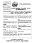
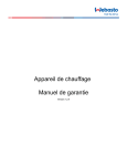
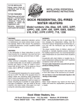
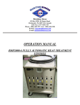
PARTS & ACCESSORIES Description / Applications The Beckett AquaSmart™ is an advanced boiler control designed for use on residential and light commercial boiler systems. All models include the option of enabling Beckett HeatManager™ dynamic temperature reset that, when selected, provides up to 20% fuel consumption savings. The control includes a backlit LCD digital display with touch pad to easily program temperature limits, differentials, and other advanced options. The AquaSmart™ also has memory storage of system history for help with diagnostics and troubleshooting. Table of Contents Features........................................................................ 2 Technical Specifications ............................................. 3 Electrical Ratings .......................................................................... 3 Temperature Ranges and Differentials .......................................... 3 Environmental Ratings .................................................................. 3 Approvals ...................................................................................... 3 Installation.................................................................... 4 Mounting ....................................................................................... 4 AquaSmart Models and Cross-Reference Guide .......................... 5 Removing the Control to be Replaced .......................................... 7 Installing the Temperature Sensor ................................................ 7 Installing the 2-in-1 Sensor ........................................................... 8 2-in-1 Sensor Technical Specifications ......................................... 8 2-in-1 Installation Instructions ....................................................... 9 Test the Low Water Cut-off (LWCO) Safety Function .................... 9 Installing the AquaSmart Control ..................................................... 10 Immersion Well or 2-in-1 Sensor ................................................ 10 Appliance Surface ...................................................................... 10 Wiring ........................................................................ 10 Wiring the AquaSmart Control.....................................................11 Programming Basic Functions ................................ 25 A. Temperature High Limit .......................................................... 25 B. Temperature Low Limit........................................................... 25 C. Temperature High Limit Differential ....................................... 25 D. Temperature Low Limit Differential ........................................ 26 Programming Additional Options ............................ 26 A. Changing the Heat Manager Settings.................................... 26 B. Viewing the Boiler Cycle History ............................................ 26 C. Changing the Circulator Settings ........................................... 27 D. Changing Domestic Hot Water Priority (DHWP) Setting ....... 28 E. Selecting Fahrenheit or Celsius Temperature Display ........... 28 F. Changing Low Water Cut-Off (LWCO) Setting ....................... 28 AquaSmart Operation ............................................... 30 Control Checkout Procedure ...................................................... 30 How a Boiler Control Works ....................................................... 31 Display Boiler Status Mode ........................................................ 32 Troubleshooting ........................................................ 32 Lockout....................................................................................... 32 HeatManager Technology ......................................... 32 Final Checklist ........................................................... 33 Accessories ............................................................... 33 Service ........................................................................ 33 Mounting Template .................................................... 35 Limited Warranty Information .................................. 36 Features ○ HeatManager™ dynamic temperature reset for additional energy savings — DOE 2012 Compliant — Meets NR CAN proposed 2012 requirements ○ Advanced microprocessor-based design ○ Backlit LCD digital display with installer programming touch pad ○ Quick access to system cycle history ○ Onboard power disconnect switch (optional) ○ High/Low limit and High/Low differential adjustments ○ 24Vac Thermostat compatible ○ Circulator control - 120Vac ○ Zone Control - 120Vac (programmable priority override for domestic hot water) ○ Temperature sensor mounts in standard immersion wells ○ Compatible retrofit for most standard boiler temperature controls ○ Programmable circulator-on and -off delays ○ Helps prevent freeze-up by energizing circulator and ZC if an error condition is detected. ○ Periodically exercises circulator pump to help prevent sieze-up. ○ Cold-start compatible ○ 6-pin vent damper receptacle on 7500B for easy wiring to most vent dampers. Electrical Shock, Fire, Explosion and Burn Hazards This control must be installed, adjusted and put into operation only by a trained, licensed, qualified professional or service agency in accordance with the National Electric Code ANSI/NFPA 70 (Canada CSA C22.1) state, local codes and authorities having jurisdiction. y The installer must carefully read and follow the installation and service instructions contained in this manual and make them available to the equipment owner, so they can be kept for future reference. y This product is not suitable for temperature control of pools, spas, or Jacuzzis. y This product is not to be used as a step or a shelf. 2 Figure 1 - Getting to know the AquaSmart 7600 Series Control Electrical Shock Hazard The AquaSmart control should only be operated with the door attached and securely closed. Communication Port TW/TR Terminals Sensor Mount Touch Pad Sensor Jack Clamping Screw For Sensor Power Disconnect Switch (Optional) Pull door up Door Removal Rotate door until grooves are aligned Technical Specifications Do Not Use This Control in an Application that is Not Within the Ratings Listed in This Section. Improper Control Operation May Result. Electrical Ratings Input Voltage: 120 Vac - 50/60 Hz. Input Current: 0.1 A + B1 + C1 + ZC MAX Input Current: 20A (Reduce to 15A if optional power disconnect switch is used) 24 Vac Thermostat Anticipator Current: 0.1 Amp. Burner Current Rating (B1): 7600A (oil): 7.4 A at 120 Vac FLA; 44.4 A inrush LRA. 7600B (gas): 1.25 A at 24 Vac; 30 VA (total load). Circulator Current Rating (C1): 7.4 A at 120 Vac FLA; 44.4 A inrush LRA. Zone Control Current Rating (ZC): 7.4 A at 120 Vac FLA; 44.4 A inrush LRA. AquaSmart Boiler Control Manual Temperature Ranges and Differentials ○ ○ ○ ○ ○ High Limit Setting Range: 100 to 240°F (37 to 115°C) High Limit Differential Range: 5 to 45°F (2 to 25°C) Low Limit Setting Range: 100 to 220°F (37 to 104°C) Low Limit Differential Range: 10 to 45°F (5 to 25°C) Factory Range Stops available - consult factory Environmental Ratings ○ ○ ○ ○ Storage Temperature: -40 to +150°F (-40 to +65°C) Operating Temperature: -4 to +150°F (-20 to +65°C) 7600B at 50 Hz: -4 to +140°F (-20 to +60°C) Maximum Sensing Element Temperature: 250°F (121°C) Relative Humidity: 5 to 85% RH, non-condensing and non-crystallizing Approvals Underwriters Laboratories Listed to UL353, UL1998 for U.S. and Canada; CSA C22.2 No. 24 3 Figure 2 - Basic Dimensions (inches) 3.51 4.92 4.50 3.04 6.50 SK10013 5.38 .75 3.50 Installation Figure 3 - Mounting Options Sensor/Immersion Well Mounting: Mounting OEM Installation: When replacing an OEM-installed AquaSmart, consult the appliance manufacturer’s wiring diagrams and instructions for additional information. Retrofit Installation: The AquaSmart can be used to replace most standard boiler temperature controls. For a cross-reference of compatible replacements, refer to Table 1. There are two basic methods for mounting the AquaSmart to the boiler as outlined in Figure 3. 1. Sensor/Immersion Well Mounting – This is the most common method. If the existing well is not suitable for any reason, a standard design aftermarket immersion well with the proper dimensions can be purchased from a HVAC distributor. The AquaSmart can then be mounted in the typical way. 2. Surface Mounting – This is sometimes required and is part of the AquaSmart base design. The base has adequate clearance built-in to accommodate the temperature sensor lead exiting the back of the control. A remote mounting kit (Pt. No. 7600RMU) that includes a 48” extension cable and mounting screws can be purchased separately for applications where needed. 4 Surface Mounting: Position the strain relief over the hex, capturing the sensor cable and crimp to secure. Sensor Lead (a 48” extension cable can be purchased separately) AquaSmart Models and Cross-Reference Guide Table 1a - Direct Replacements Honeywell Beckett Replacement Notes L7148F (All) L8148E (All) 7600B Must confirm that 7600 VA rating is adequate to meet VA requirements of system. Make sure 7600 B1 output does not exceed 1.25A @ 24VAC (30 VA). 7600 outputs are not rated for 240 VAC. B2, TW and TR terminals replace TV, T and Z, respectively. L8124A (All) L8124C (All) 7600A 7600 outputs are not rated for 240 VAC. L7124A/C (All) L7148A (All) L7224A/C/U (All) L7248A/C (All) 7600A The 7600 has no Honeywell EnviraCOMTM Communications port. The diagnostic LED lights are replaced by the 7600’s display. L8148A (All) 7600A 7600 outputs are not rated for 240 VAC. B1 terminal on 7600 utilizes a 1/4” quick connect. Set low limit on 7600 to OFF. L8124E 1016 L8148E 1265 7600B 7600 outputs are not rated for 240 VAC. B2, TW and TR terminals replace TV, T and Z, respectively. L8124M (All) 7600A For replacement with the 7600: Turn low limit off so the circulator is controlled directly by the thermostat and ZC is constantly powered. L8151A 7600A 7600 outputs are not rated for 240 VAC. Remote mount sensor cable needed (Part No. 52120) Hydrolevel Beckett Replacement Notes 3100 7600B Not a suitable replacement if Low Water Cutoff (LWCO) functionality of the 3100 is used. 3150 7600A Not a suitable replacement if Low Water Cutoff (LWCO) functionality of the 3150 is used. Carlin Beckett Replacement 90524A 7600A White Rodgers Beckett Replacement 11C15-11 7600A 8B48A-217 7600A 11C30-3 11B54-4 7600A 8F48A-351 8B43A-601 7600B 11C61-12 7600A Notes Make sure 7600 outputs do not exceed 7.4A. Available operating limit and differential ranges are not equivalent. Compare the settings to the AquaSmart ranges before replacing. The diagnostic LED lights are replaced by the 7600’s display. Notes Make sure 7600 outputs do not exceed 7.4A @ 120 VAC. 7600 outputs are not rated for 240 VAC. Make sure 7600 outputs do not exceed 7.4A @ 120 VAC. 7600 outputs are not rated for 240 VAC. Available operating limit and differential ranges are not equivalent. Compare the settings to the AquaSmart ranges before replacing. Not a suitable replacement if SPDT switch action is required; only break-on-rise available on 7600. Make sure 7600 outputs do not exceed 7.4A @ 120 VAC. 7600 outputs are not rated for 240 VAC. Burn, Scald, Explosion, and Equipment Malfunction Hazard Replacement of the following controls must be done only by a qualified service agency or technician who is trained and experienced in the use of boiler controls. Carefully follow these guidelines and the directions provided by the manufacturer of the control being replaced. Note: Beckett assumes no liability for incorrect installation or replacement. Table 1b - Functional Replacement (Advanced Wiring Needed) Honeywell Beckett Replacement (Table continued on next page) Notes L4006A (All) L4006G 1022 L4006H 1004 L4008A (All) L4080B/D 7600A or 7600B (Based on System Voltage Requirements) Make sure 7600 outputs do not exceed 7.4A @ 120 VAC. 7600 outputs are not rated for 240 VAC. 7600 will require an additional wire (L2) for operation. Short TW-TR terminals. C1, C2, ZC, and ZR are unused. Set low limit on 7600 to OFF. Available operating limit and/or differential ranges may not be equivalent. Compare the settings to the AquaSmart ranges before replacing. To use with a millivolt system, an appropriate voltage relay with isolated gold plated contacts must be added to switch the millivolt circuit. L4006E (All) L4008E (All) L4080F/G 7600A or 7600B (Based on System Voltage Requirements) Requires the addition of a manual-reset high limit. Make sure 7600 outputs do not exceed 7.4A @ 120 VAC. 7600 outputs are not rated for 240 VAC. 7600 will require an additional wire (L2) for operation. Short TW-TR terminals. C1, C2, ZC, and ZR are unused. Set low limit on 7600 to OFF. Available operating limit and/or differential ranges may not be equivalent. Compare the settings to the AquaSmart ranges before replacing. To use with a millivolt system, an appropriate voltage relay with isolated gold plated contacts must be added to switch the millivolt circuit. AquaSmart Boiler Control Manual 5 Table 1b (continued from previous page) Honeywell 6 Beckett Replacement Notes L4081A/B L6081A/C 7600A or 7600B (Based on System Voltage Requirements) Remove switching relay, if used, from the system when replacing the L4081 or L6081. Make sure 7600 outputs do not exceed 7.4A @ 120 VAC. 7600 outputs are not rated for 240 VAC. L6006A (All) L6006C 1018 L6008A 1192 L6008A 1242 7600A or 7600B (Based on System Voltage Requirements) Not a suitable replacement if SPDT switch action is required; only break-on-rise available on 7600. To use with a millivolt system an appropriate voltage relay with isolated gold plated contacts must be added to switch the millivolt circuit. Make sure 7600 outputs do not exceed 7.4A @ 120 VAC. 7600 outputs are not rated for 240 VAC. 7600 will require an additional wire (L2) for operation. Short TW-TR terminals. C1, C2, ZC, and ZR are unused. Set low limit on 7600 to OFF. Available operating limit and/or differential ranges may not be equivalent. Compare the settings to the AquaSmart ranges before replacing. L8124B 1039 L8148J 1009 7600A or 7600B (Based on System Voltage Requirements) To use with a millivolt system an appropriate voltage relay with isolated gold plated contacts must be added to switch the millivolt circuit. 7600 outputs are not rated for 240 VAC. Carlin Beckett Replacement 90200A 7600A or 7600B (Based on System Voltage Requirements) Make sure 7600 outputs do not exceed 7.4A. Set low limit on 7600 to OFF. Available operating limit and differential ranges are not equivalent. Compare the settings to the AquaSmart ranges before replacing. 90000 (All) 90200E 90200EL 90300B 7600A or 7600B (Based on System Voltage Requirements) Requires the addition of a manual-reset high limit. Make sure 7600 outputs do not exceed 7.4A. Set low limit on 7600 to OFF. Available operating limit and differential ranges are not equivalent. Compare the settings to the AquaSmart ranges before replacing. 90200D 7600A or 7600B (Based on System Voltage Requirements) Not a suitable replacement if SPDT switch action is required; only break-on-rise available on 7600. Make sure 7600 outputs do not exceed 7.4A. Set low limit on 7600 to OFF. Available operating limit and differential ranges are not equivalent. Compare the settings to the AquaSmart ranges before replacing. Notes White Rodgers Beckett Replacement 11B06-1 11D18-1 11B18-101 11B30-104 11B02-1 1145-33 7600A or 7600B (Based on System Voltage Requirements) Make sure 7600 outputs do not exceed 7.4A @ 120 VAC. 7600 outputs are not rated for 240 VAC. 7600 will require an additional wire (L2) for operation. Short TW-TR terminals. C1, C2, ZC, and ZR are unused. Set low limit on 7600 to OFF. 11B06-46 11B95-31 11B18-153 7600A or 7600B (Based on System Voltage Requirements) Make sure 7600 outputs do not exceed 7.4A @ 120 VAC. 7600 outputs are not rated for 240 VAC. 7600 will require an additional wire (L2) for operation. Short TW-TR terminals. C1, C2, ZC, and ZR are unused. Set low limit on 7600 to OFF. Available operating limit and/or differential ranges are not equivalent. Compare the settings to the AquaSmart ranges before replacing. 11D82-1 11D31-1 1131-102 1127-2 11A79-2 7600A or 7600B (Based on System Voltage Requirements) Not a suitable replacement if SPDT switch action is required; only break-on-rise available on 7600. 7600 outputs are not rated for 240 VAC. 7600 will require an additional wire (L2) for operation. Short TW-TR terminals. C1, C2, ZC, and ZR are unused. Set low limit on 7600 to OFF. 1127-9 7600A or 7600B (Based on System Voltage Requirements) Not a suitable replacement if SPDT switch action is required; only break-on-rise available on 7600. 7600 outputs are not rated for 240 VAC. 7600 will require an additional wire (L2) for operation. Short TW-TR terminals. C1, C2, ZC, and ZR are unused. Set low limit on 7600 to OFF. Available operating limit and/or differential ranges may not be equivalent. Compare the settings to the AquaSmart ranges before replacing. 11B27-9 7600A or 7600B (Based on System Voltage Requirements) Requires the addition of a manual-reset high limit. Make sure 7600 outputs do not exceed 7.4A @ 120 VAC. 7600 outputs are not rated for 240 VAC. 7600 will require an additional wire (L2) for operation. Short TW-TR terminals. C1, C2, ZC, and ZR are unused. Set low limit on 7600 to OFF. Available operating limit and/or differential ranges are not equivalent. Compare the settings to the AquaSmart ranges before replacing. 8J48A-209 7600A or 7600B (Based on System Voltage Requirements) To use with a millivolt system an appropriate voltage relay with isolated gold plated contacts must be added to switch the millivolt circuit. Notes Removing the Control to be Replaced Electrical shock hazard. Disconnect all electrical power to the appliance circuit before replacing the control. There may be more than one disconnect switch. 1. Compare the attached wires to available wiring diagrams on the control cover and to the devices to which they can be traced. If wiring diagrams have been lost they are available later in this manual. 2. Label each wire accordingly, to ensure accurate reconnection. (Masking tape works well for labeling.) 3. Remove each wire from the old control. Make sure each label is intact. 4. Loosen the control mounting arrangement and remove the control from the system. 5. Make note of the temperature settings for high limit, low limit and differentials. This will provide important reference data for the new control adjustment. Please note that differentials may be used differently in other manufacturer’s controls. See Figure 19 & 16 toward end of manual for a description of how the AquaSmart’s differentials work. Consult the manual of the control being replaced for information regarding its differentials. Installing the Temperature Sensor 1. Make sure the immersion well is clean inside, has no leaks, is of proper length and is otherwise suitable for receiving the new control and temperature sensor. 2. Replace questionable wells with new ones and use pipe sealant to seal the threads. 3. Grasp the sensor lead, just behind the sensor probe and carefully insert it into the well until it comes to rest at the very end of the well. The sensor is designed with radial splines to provide a snug fit in most standard wells. 4. The thermal time constant of the sensor is 40 seconds. Consider using thermal grease if faster response in desired. 5. Surface mounting may require additional lead length to reach the control receptacle. Use the extension cable (part no. 52120), found in the 7600RMU Remote Mount Kit, to extend the lead by 48”. 6. Install the strain relief (part no. 3266201) as shown, capturing the cable against the hex. Crimp the strain relief opposite side of the cable. This anchors the sensor securely inside the immersion well. 7. Plug the temperature sensor lead terminal into the receptacle on the control base. See Figure 10. Note: The sensor is not tested and approved for being mounted to the outside of a pipe. It is for use in immersion wells only. Figure 4b - Strain Relief This is very important for successful control operation. Burn and Scald Hazard Excessive water temperatures could cause explosion, burns, scalding, pressure relief flooding and fitting leaks. y Carefully follow the outlined procedures for temperature sensor installation to ensure accurate water temperature sensing and effective control operation. y Make sure the plumbing for domestic hot water has anti-scald valve protection. Figure 4a - Installation of Temperature Sensor in Immersion Well Sensor must butt against end Brass Fitting Temperature Sensor Copper Well Tube AquaSmart Boiler Control Manual Sensor connects to Beckett AquaSmart 7 Installing the 2-in-1 Sensor Do not use in steam applications. For use in hot water boilers or water heaters only. Do not use outside of the intended use and specifications. Explosion, Burn and Scald Hazards Excessive water temperatures could cause explosion, burns, scalding, pressure relief flooding and fitting leaks. Leak, Burn, and Scald Hazards Incompatible thread sealants could severely damage the sensor threads. y The sensor must be installed in the proper location for correct low water cut-off (LWCO) operation in accordance with the Boiler Manufacturer’s instructions. y The 2-in-1 Sensor shall only be installed by a trained professional. y Only use Teflon® Tape or Rectorseal® No. 5® (soft-set). y The 2-in-1 sensor body is installed directly into the boiler wall tapped hole in place of an immersion well. y DO NOT use any anaerobic fast-setting sealants such as, but not limited to, Loctite®, Leak Lock®, Permatex®, or Gasoila®. y Carefully follow the outlined procedures for temperature sensor installation to ensure accurate water temperature sensing and effective control operation. y Call RWB Technical Services at 1(800)645-2876 to confirm, if unsure. y Make sure the plumbing for domestic hot water has anti-scald valve protection. For proper operation, there must be a secure electrical bond between the green sensor wire from the sensor and the boiler metal vessel in direct contact with the boiler water. Failure to secure an electrical bond will result in the AquaSmart locking out and displaying, “LOCKOUT - LOW WATER”. y Follow all applicable safety codes, rules and guidelines for installing an immersion well. Improper installation can result in the Boiler overheating. Figure 5 - Overall Dimensions & Specifications B A C 1-1/8” hex A B C Lead Length Insulation Depth Insertion Depth 76002N1S01 8-1/4” 1-1/2” 1-5/8” Storage Temperature Range -40° to 250°F 76002N1S02 6-1/4” 3-1/2” 1-5/8” Operating Temperature Range -32° to 250°F 76002N1S05 5” 4-3/4” 1-5/8” Maximum Pressure 250 PSIG 76002N1S06 8-1/4” 1-1/2” 7/8” Installation Torque Range (Screw-in) 185 - 200 in/lbs. Part No. 8 Specifications 2-in-1 Installation Instructions Figure 6 - Sensor lead & ground screw connections This is very important for successful control operation. 1. Remove the existing immersion well. Clean the threads in the boiler port tapping. Follow all applicable safety codes, rules and guidelines for removing/ installing immersion wells. 2. Apply pipe sealant to the 2-in-1 sensor threads and install it securely into the port. BECKETT RECOMMENDS ONLY TO USE TEFLON TAPE OR RECTORSEAL NO. 5 PIPE SEALANT. 3. Tighten with 1-1/8” open end or box wrench. Pipe wrenches, pliers, and adjustable wrenches will damage/round-off the hex. 4. Securely install the AquaSmart control to the sensor. Plug the 2-in-1 Sensor RJ connector (phone jack style) into the receptacle (Item a, Figure 6) on the control. 5. Route the 36” green wire through the AquaSmart bottom rectangular slot (Item c, Figure 6). Securely install the fork connector of the 36” ground wire and the ground wire from the 2-in-1 sensor under the ground screw at the bottom of the control (Item b, Figure 6). a c b Figure 7 - Ground Clamp and Grounding Wire 6. Thoroughly clean the pipe surface and securely tighten the pipe clamp on the water inlet pipe to the boiler as close to the boiler as possible. d 7. Route the 36” green ground wire to the pipe clamp then cut to proper length, if necessary. 8. Strip the wire and insert the stripped end into hole on the pipe clamp (item d, Figure 7). Tighten retaining screw against the wire making sure that you have good contact. 9. Complete control wiring and fill the appliance with water to the pressure required, according to appliance manufacturer’s instructions. Make sure all air is purged from the system and there are no leaks. Turn on power to the appliance and observe one call for heat cycle with shut off at set temperature. Test the Low Water Cut-off (LWCO) Safety Function WARNING! Avoid touching or shorting the live terminals during this test. Turn electric power ON to energize AquaSmart control. Perform the following tests to verify the LWCO function. • For AquaSmart 7600A: Remove the green sensor lead from the ground screw. The sensor should cause the AquaSmart display to indicate, “LOCKOUT – LOW WATER”. If it does not, replace the sensor. • For AquaSmart 7600B: Remove the green sensor lead from the ground screw and remove both the B1 and B2 (24 Vac) leads from their terminals. The sensor should cause the AquaSmart display to indicate, “LOCKOUT – LOW WATER”. If it does not, replace the sensor. • Attach wires and tighten terminal screws securely when testing is complete. AquaSmart Boiler Control Manual Figure 8 - Sensor Water Detection Method AquaSmart Boiler Control 2-IN-1 SENSOR Ground Screw Water Not Present Water Present Ground Wire Pipe Clamp Incomplete Circuit Complete Circuit Water Inlet The AquaSmart 2-in-1 Sensor uses the “conduction” method to detect whether water is present in the boiler. This is done by using the water in the boiler itself to “conduct” a signal and complete an electrical circuit. It is necessary that the ground wire from the sensor be bonded to the boiler wall (not the jacket unless the jacket is bonded to the boiler wall). When water is not present, there is no “conduction” and the circuit is incomplete. For the AquaSmart we recommend that a grounding pipe clamp be mounted to the water inlet pipe, and that a ground wire be bonded from the pipe clamp to the green terminal inside the AquaSmart control. The 2-in-1 sensor green “ground wire” shall also be bonded to the green terminal in the AquaSmart control. 9 Installing the AquaSmart Control (Refer back to Figure 3 for appropriate mounting method). Figure 9 - Mounting Clamp and Screw for Immersion Well For clarity, the printed circuit board is not shown. Immersion Well or 2-in-1 Sensor 1. Mount the control by aligning the 7/8” diameter hole (found on back) around the mating feature of the immersion well or 2-in-1 sensor and press into place. Position the control upright and tighten down the #10 screw located on the left side of the control. Tighten so that control is securely in place (Figure 9). 2. Plug the temperature sensor lead terminal into the receptacle on the control base. See Figure 10. Figure 10 - Temperature Sensor Lead/Receptacle Appliance Surface 1. Use the AquaSmart mounting template to locate the mounting holes in a desired location on mounting surface. The template can be found in the back of this manual. 2. Use (3) #8 x 3/4” self drilling screws (.110 hole diameter if pre-drilling) included in the installation kit. Run screws into mounting surface, leaving a 1/4” space between bottom of screw head and mounting surface. 3. Open the cover of the AquaSmart control to expose key hole locations in plastic case. Align key holes over mounting screws and secure in place. 4. Plug the temperature sensor lead terminal into the receptacle on the control base. See Figure 10. 5. If necessary, use the 48” cable extension to connect sensor to control base. Refer back to Figure 3. Wiring Electrical Shock, Fire, Explosion and Burn Hazards This control must be installed, adjusted and put into operation only by a trained, licensed, qualified professional or service agency in accordance with the latest revision of the National Electric Code ANSI/ NFPA 70 (Canada CSA C22.1) state, local codes and authorities having jurisdiction. y Follow the appliance manufacturer’s wiring diagrams and note all safety controls. y Typical safety controls include high temperature or pressure limits, low water cutoffs, anti-scald valves, pressure relief valves and water feed valves. y Verify all limits and safety controls are installed and functioning correctly, as specified by the appliance manufacturer, applicable safety standards, codes and all authorities having jurisdiction. y Provide ground wiring to the appliance, burner and controls. 10 Electrical Shock Hazard. Can Cause Severe Injury, Death, or Equipment Damage. Disconnect power before wiring to prevent electrical shock or equipment damage. y All wiring must comply with local electrical codes and ordinances. The limits given in the specifications section must not be exceeded when applying this control. Terminals on the AquaSmart are approved for copper wire only. y Refer to the label on the inside of the AquaSmart door or to Technical Specifications in this manual for Electrical ratings and maximum load information. Use manufacturer instructions when wiring controlled equipment or refer to typical hookups in Figure 12 through Figure 17. y More than one service switch may be needed to disconnect all power to the AquaSmart. The optional power disconnect switch interrupts power to the AquaSmart control. Depending on system wiring, some terminals and connections (most notably ZR and the input to the optional power disconnect switch) may still be live. Explosion Hazard. Can Cause Severe Injury, Death or Property Damage. Use this product only in systems with a pressure relief valve. Wiring the AquaSmart Control ○ ○ ○ ○ ○ ○ Consult the appliance wiring diagrams to check the manufacturer’s specifications. Refer to Figure 12 through Figure 17 for some typical wiring diagrams. Verify the wires are still labeled correctly and make connections to the appropriate terminals on the control wiring terminal strip. Provide disconnect means and overload protection as required on power supply. Connect control conduit bracket to earth ground using the supplied grounding screw. B1 terminal is a 1/4 in. tab terminal (quick connect). Some Thermostats Are Polarity Sensitive Reversed polarity could cause erratic cycling of the boiler control. y Connect the red thermostat wire (from the RH or R terminal of the thermostat) to the TR terminal on the control. 7600B only: TERMINALS TR (Z or hot) and B2 (TV or ground) offer a 24-volt supply for operating other 24 VAC equipment on the boiler. IMPORTANT: TO PREVENT DAMAGE TO THE CONTROL, DO NOT OVERLOAD THE TRANSFORMER. The AquaSmart is equipped with a 30VA transformer. Make sure that the total load, including the burner circuit and TR & B2 connections do not exceed 30VA. See Figure 11. How to calculate VA - Add all AMP ratings of 24VAC components in this circuit and multiply sum by 24 volts. (Example: .4 + .4 + .2 + .2 = 1.2A x 24V = 28.8 VA) When powering multiple circulators from the C1 and C2 terminals, take extra care not to exceed the output’s reading. If the sum of the full load amps of all the circulators exceeds the output’s rating, use the C1 and C2 terminals to power the coil of a multiple-pole contactor; the contacts of which can be wired to switch L1 to each circulator. To wire a vent damper to the 7600B, first remove jumper plug from 6position receptacle and then connect 6-pin connector of the vent damper to the receptacle. See Figure 11. Once the 7600B is operated with a vent damper, it will not function without one (even if the jumper plug is replaced). Water Flow Symbols Key (Figures 12 through 17) y Connect the white thermostat wire (from the W terminal of the thermostat) to the TW terminal on the control. - Air Vent - Air Separator Figure 11 - TR, B2, & Vent Damper Connections - Expansion Tank TR - Isolation Valve 6-Position Vent Damper Receptacle - Pressure Regulator Z - Zone Valve B2 - Check Valve Observe proper polarity when wiring L1 and L2. If polarity is reversed, a call for heat on the ZR input may not be recognized. AquaSmart Boiler Control Manual - Circulator 11 Figure 12 - 7600A/B single-zone connections with or without a tankless coil AIR VENT Water Flow: AIR SEPARATOR SK10030 P1 HEATING ZONE EXPANSION TANK COLD WATER INLET Control Wiring: SK10019 1. Set “DHWP OFF” (default, see programming section for instructions) 2. Set “C1 on TT” (default, see programming section for instructions) TW TR L2 C1 C2 ZC ZR B1 B2 FIELD/MFR. SUPPLIED SERVICE SWITCH BLACK WHITE HOT P1 CIRCULATOR 120 VAC 12 RED LOW VOLTAGE THERMOSTAT WHITE 120 VAC BLACK NEUTRAL L1 WHITE 7600A: 120 VAC BURNER OR GAS IGNITION SYSTEM 7600B: 24 VAC GAS IGNITION SYSTEM Figure 13 - 7600A/B multi-zone connections with or without a tankless coil * Additional zones can be added by duplicating the plumbing and wiring of zone 3. Water Flow: AIR VENT AIR SEPARATOR SK10031 P3* P2 P1 HEATING ZONE 1 HEATING ZONE 2 HEATING ZONE 3* EXPANSION TANK COLD WATER INLET Control Wiring (Option 1): Circulator-On and -Off Delays on Zone 1 ONLY 1. Set “DHWP OFF” (default, see programming section for instructions) 2. Set “C1 on TT” (default, see programming section for instructions) 3. Circulator-on and -off delays will only affect zone 1 SK10020 CIRCULATOR 120 VAC P3* TW TR WHITE RED ZONE 1 LOW VOLTAGE THERMOSTAT 6 ZONE RELAY 5 4 3 L2 L1 C1 C2 ZC ZR B1 B2 2/N T 1/H T ZONE 3* LOW VOLTAGE THERMOSTAT CIRCULATOR 120 VAC P1 CIRCULATOR 120 VAC 7600A: 120 VAC BURNER OR GAS IGNITION SYSTEM 7600B: 24 VAC GAS IGNITION SYSTEM P2 6 ZONE RELAY 5 4 3 NEUTRAL WHITE 120 VAC HOT FIELD/MFR. SUPPLIED SERVICE SWITCH BLACK AquaSmart Boiler Control Manual 2/N T 1/H T ZONE 2 LOW VOLTAGE THERMOSTAT CONTINUED ON NEXT PAGE ► 13 Figure 13 (continued) - 7600A/B multi-zone connections with or without a tankless coil * Additional zones can be added by duplicating the plumbing and wiring of zone 3. ◄ CONTINUED FROM PREVIOUS PAGE Control Wiring (Option 2): Circulator-On Delay on All Zones 1. Set “DHWP OFF” (default, see programming section for instructions) 2. Set “C1 on ZR” (see programming section for instructions) 3. Circulator-on delay will affect all zones. Circulator-off delay will have no effect. CIRCULATOR 120 VAC P3* 6 ZONE RELAY 5 4 3 2/N T 1/H T LOW VOLTAGE THERMOSTAT CIRCULATOR 120 VAC SK10032 ZONE 3* P2 TW TR 6 ZONE RELAY 5 4 3 L2 L1 C1 C2 ZC ZR B1 B2 2/N T 1/H T LOW VOLTAGE THERMOSTAT CIRCULATOR 120 VAC 7600A: 120 VAC BURNER OR GAS IGNITION SYSTEM 7600B: 24 VAC GAS IGNITION SYSTEM ZONE 2 P1 6 ZONE RELAY 5 4 3 NEUTRAL WHITE 120 VAC HOT 14 FIELD/MFR. SUPPLIED SERVICE SWITCH BLACK 2/N T 1/H T ZONE 1 LOW VOLTAGE THERMOSTAT * Additional zones can be added by duplicating the plumbing and wiring of zone 3, adding additional transformers as needed. Figure 14 - 7600A/B alternate multi-zone connections with or without a tankless coil Water Flow: AIR VENT AIR SEPARATOR GENERAL CIRCULATOR SK10033 Z ZONE 1 24 VAC ZONE VALVE Z ZONE 2 24 VAC ZONE VALVE Z HEATING ZONE 2 HEATING ZONE 1 ZONE 3* 24 VAC ZONE VALVE HEATING ZONE 3* EXPANSION TANK COLD WATER INLET Control Wiring (Option 1): 7600B only 1. Set “DHWP OFF” (default, see programming section for instructions) 2. Set “C1 on TT” (default, see programming section for instructions) 3. Circulator-on delay will affect all zones. Circulator-off delay will have no effect. 4. Up to two 24 VAC zone valves can be powered with the 7600B. Add an additional transformer as shown for every two or less valves over the original two. 5. Ensure there are no jumpers between the terminals of the zone valves. ZONE 1 LOW VOLTAGE THERMOSTAT ZONE 2 24 VAC ZONE VALVE ZONE 3* 24 VAC ZONE VALVE Taco 550 Honeywell V8043E, V8044E Honeywell V8043F 1 SK10021 3 TR ZONE 3* LOW VOLTAGE THERMOSTAT ZONE 1 24 VAC ZONE VALVE MTR TW ZONE 2 LOW VOLTAGE THERMOSTAT Y MTR Y TR TH MTR 2 R TH/ TR R T Z TV L2 NEUTRAL 120 VAC HOT L1 WHITE BLACK FIELD/MFR. SUPPLIED SERVICE SWITCH 40 VA TRANSFORMER C1 C2 ZC ZR B1 B2 GENERAL CIRCULATOR 24 VAC GAS IGNITION SYSTEM CIRCULATOR 120 VAC CONTINUED ON NEXT PAGE ► AquaSmart Boiler Control Manual 15 Figure 14 (continued) - 7600A/B alternate multi-zone connections with or without a tankless coil * Additional zones can be added by duplicating the plumbing and wiring of zone 3, adding additional transformers as needed. ◄ CONTINUED FROM PREVIOUS PAGE Control Wiring (Option 2): 7600A only 1. Set “DHWP OFF” (default, see programming section for instructions) 2. Set “C1 on TT” (default, see programming section for instructions) 3. Circulator-on delay will affect all zones. Circulator-off delay will have no effect. 4. 24 VAC zone valves cannot be powered directly with the 7600A. Add an additional transformer for every two or less valves. 5. Ensure there are no jumpers between the terminals of the zone valves. ZONE 1 LOW VOLTAGE THERMOSTAT ZONE 3* LOW VOLTAGE THERMOSTAT ZONE 1 24 VAC ZONE VALVE ZONE 2 24 VAC ZONE VALVE ZONE 3* 24 VAC ZONE VALVE Taco 550 Honeywell V8043E, V8044E Honeywell V8043F 1 MTR SK10046 ZONE 2 LOW VOLTAGE THERMOSTAT 3 Y MTR Y 2 R R TR NEUTRAL 120 VAC HOT 16 L1 WHITE BLACK FIELD/MFR. SUPPLIED SERVICE SWITCH 40 VA TRANSFORMER C1 C2 ZC ZR B1 B2 GENERAL CIRCULATOR CIRCULATOR 120 VAC 120 VAC BURNER OR GAS IGNITION SYSTEM TH MTR TW L2 TR 40 VA TRANSFORMER TH/ TR Figure 15 - 7600A/B single-zone connections with Indirect Domestic Hot Water (DHW) Water Flow: AIR VENT AIR SEPARATOR P1 P2 SK10034 INDIRECT DHW HEATING ZONE 1 DHW ZONE EXPANSION TANK COLD WATER INLET Control Wiring: SK10023 1. Set “DHWP on ZR” (see programming section for instructions) 2. Set “C1 on TT” (default, see programming section for instructions) 3. Circulator-on and -off delay will only affect zone 1. TW TR WHITE RED ZONE 1 LOW VOLTAGE THERMOSTAT L2 NEUTRAL 120 VAC HOT L1 C1 C2 ZC ZR B1 B2 P2 WHITE BLACK FIELD/MFR. SUPPLIED SERVICE SWITCH CIRCULATOR 120 VAC P1 CIRCULATOR 120 VAC 7600A: 120 VAC BURNER OR GAS IGNITION SYSTEM 7600B: 24 VAC GAS IGNITION SYSTEM 6 ZONE RELAY 5 4 DHW LIMIT CONTROL 3 AquaSmart Boiler Control Manual 2/N T 1/H T 17 Figure 16 - 7600A/B multi-zone connections with Indirect Domestic Hot Water (DHW) * additional zones can be added by duplicating the plumbing and wiring of zone 3. Water Flow: AIR VENT AIR SEPARATOR P2 SK10035 P1 INDIRECT DHW DHW ZONE HEATING ZONE 1 P3 HEATING ZONE 2 P4* HEATING ZONE 3* EXPANSION TANK COLD WATER INLET CONTINUED ON NEXT PAGE ► 18 Figure 16 (continued)- 7600A/B multi-zone connections with Indirect Domestic Hot Water (DHW) * Additional zones can be added by duplicating the plumbing and wiring of zone 3. ◄ CONTINUED FROM PREVIOUS PAGE Control Wiring (Option 1): Circulator-On and -Off Delays on DHW Zone Only 1. Set “DHWP on TT” (see programming section for instructions) 2. Set “C1 on TT” (default, see programming section for instructions) 3. Circulator-on and -off delays will only affect DHW zone. CIRCULATOR 120 VAC P4* 6 ZONE RELAY 5 4 3 2/N T 1/H T ZONE 3* LOW VOLTAGE THERMOSTAT SK10022 CIRCULATOR 120 VAC DHW LIMIT CONTROL TW TR P3 6 ZONE RELAY 5 4 3 L2 L1 C1 C2 ZC ZR B1 B2 2/N T 1/H T LOW VOLTAGE THERMOSTAT CIRCULATOR 120 VAC P1 CIRCULATOR 120 VAC 7600A: 120 VAC BURNER OR GAS IGNITION SYSTEM 7600B: 24 VAC GAS IGNITION SYSTEM ZONE 2 P2 6 ZONE RELAY 5 4 3 NEUTRAL WHITE 120 VAC HOT FIELD/MFR. SUPPLIED SERVICE SWITCH BLACK 2/N T 1/H T ZONE 1 LOW VOLTAGE THERMOSTAT CONTINUED ON NEXT PAGE ► AquaSmart Boiler Control Manual 19 Figure 16 (continued) - 7600A/B multi-zone connections with Indirect Domestic Hot Water (DHW) * Additional zones can be added by duplicating the plumbing and wiring of zone 3. ◄ CONTINUED FROM PREVIOUS PAGE Control Wiring (Option 2): Circulator-On Delay on All Zones 1. Set “DHWP OFF” (default, see programming section for instructions) 2. Set “C1 on ZR” (see programming section for instructions) 3. Circulator-on delay will affect all zones. Circulator-off delay will have no effect. 4. DHW zone will not have priority over heating zones. CIRCULATOR 120 VAC P4* 6 ZONE RELAY 5 4 3 2/N T 1/H T ZONE 3* LOW VOLTAGE THERMOSTAT CIRCULATOR 120 VAC P3 ZONE RELAY 6 5 4 3 2/N T 1/H T LOW VOLTAGE THERMOSTAT CIRCULATOR 120 VAC SK10024 ZONE 2 P2 TW 6 TR ZONE RELAY 5 4 3 L2 L1 C1 C2 ZC ZR B1 B2 2/N T 1/H T ZONE 1 LOW VOLTAGE THERMOSTAT 7600A: 120 VAC BURNER OR GAS IGNITION SYSTEM 7600B: 24 VAC GAS IGNITION SYSTEM CIRCULATOR 120 VAC P1 ZONE RELAY 6 5 4 DHW LIMIT CONTROL 3 NEUTRAL WHITE 120 VAC HOT 2/N T 1/H T FIELD/MFR. BLACK SUPPLIED SERVICE SWITCH CONTINUED ON NEXT PAGE ► 20 Figure 16 (continued) - 7600A/B multi-zone connections with Indirect Domestic Hot Water (DHW) * Additional zones can be added by duplicating the plumbing and wiring of zone 3. ◄ CONTINUED FROM PREVIOUS PAGE Control Wiring (Option 3): Utilizing a Zone Panel 1. Set “DHWP on TT” (see programming section for instructions). 2. Set “C1 on TT” (default, see programming section for instructions). 3. Circulator-on and -off delay will only effect DHW zone. 4. A call for heat on TT (from the DHW zone) will change boiler set point to the high limit. All other zones will heat to the reset temperature determined by the HeatManager. 5. Ensure that the zone panel and AquaSmart are powered from the same service switch. SK10036 ZONE 1 LOW VOLTAGE THERMOSTAT ZONE 3* ZONE 2 LOW LOW VOLTAGE VOLTAGE THERMOSTAT THERMOSTAT DHW LIMIT CONTROL TW TR X END X SWITCH ZONE PANEL Z1 Z2 Z3* L1 L2 L2 NEUTRAL 120 VAC HOT L1 WHITE C1 C2 ZC ZR B1 B2 P1 BLACK FIELD/MFR. SUPPLIED SERVICE SWITCH ZR ZC CIRCULATOR 120 VAC 7600A: 120 VAC BURNER OR GAS IGNITION SYSTEM 7600B: 24 VAC GAS IGNITION SYSTEM P3 P2 P4* CIRCULATOR 120 VAC CIRCULATOR CIRCULATOR 120 VAC 120 VAC AquaSmart Boiler Control Manual 21 * Additional zones can be added by duplicating the plumbing and wiring of zone 3, adding additional transformers as needed. Figure 17 - 7600A/B alternate multi-zone connections with Indirect Domestic Hot Water (DHW) Water Flow: AIR VENT SK10037 AIR SEPARATOR Z Z Z Z DHW ZONE 24 VAC ZONE VALVE ZONE 1 24 VAC ZONE VALVE ZONE 2 24 VAC ZONE VALVE ZONE 3* 24 VAC ZONE VALVE HEATING ZONE 1 HEATING ZONE 2 INDIRECT DHW DHW ZONE HEATING ZONE 3* EXPANSION TANK COLD WATER INLET GENERAL CIRCULATOR CONTINUED ON NEXT PAGE ► 22 * Additional zones can be added by duplicating the plumbing and wiring of zone 3, adding additional transformers as needed. Figure 17 (continued) - 7600A/B alternate multi-zone connections with Indirect Domestic Hot Water (DHW) ◄ CONTINUED FROM PREVIOUS PAGE Control Wiring (Option 1): 7600B only 1. Set “DHWP on ZR” (see programming section for instructions) 2. Set “C1 on BOTH” (see programming section for instructions) 3. Circulator-on delay will affect all zones. Circulator-off delay will have no effect. 4. Up to two 24 VAC zone valves can be powered with the 7600B. Add an additional transformer as shown for every two or less valves over the original two. 5. Ensure there are no jumpers between the terminals of the zone valves. ZONE 3* LOW VOLTAGE THERMOSTAT DHW ZONE 24 VAC ZONE VALVE ZONE 3* 24 VAC ZONE VALVE Honeywell V8043F Honewell V8043E, V8044E TR TH MTR TH/ TR Y MTR R ZONE 1 LOW VOLTAGE THERMOSTAT ZONE 2 24 VAC ZONE VALVE Honewell V8043F Taco 550 SK10038 TH MTR TH/ TR TR L2 L1 T 6 ZONE RELAY 5 C1 C2 ZC ZR B1 B2 DHW LIMIT CONTROL 4 3 NEUTRAL WHITE HOT 2 Z TV 120 VAC 1 MTR 3 TW 24 VAC GAS IGNITION SYSTEM BLACK FIELD/MFR. SUPPLIED SERVICE SWITCH R ZONE 2 LOW VOLTAGE THERMOSTAT ZONE 1 24 VAC ZONE VALVE TR Y 2/N T 1/H T 40 VA TRANSFORMER GENERAL CIRCULATOR CIRCULATOR 120 VAC CONTINUED ON NEXT PAGE ► AquaSmart Boiler Control Manual 23 * Additional zones can be added by duplicating the plumbing and wiring of zone 3, adding additional transformers as needed. Figure 17 (continued) - 7600A/B alternate multi-zone connections with Indirect Domestic Hot Water (DHW) ◄ CONTINUED FROM PREVIOUS PAGE Control Wiring (Option 2): 7600A only 1. Set “DHWP on ZR” (see programming section for instructions) 2. Set “C1 on BOTH” (see programming section for instructions) 3. Circulator-on delay will affect all zones. Circulator-off delay will have no effect. 4. 24 VAC zone valves cannot be powered directly with the 7600A. Add an additional transformer as shown for every two or less valves. 5. Ensure there are no jumpers between the terminals of the zone valves. ZONE 3* LOW VOLTAGE THERMOSTAT DHW ZONE 24 VAC ZONE VALVE ZONE 3* 24 VAC ZONE VALVE Honeywell V8043F Honewell V8043E, V8044E TR TH MTR TH/ TR Y MTR R ZONE 1 LOW VOLTAGE THERMOSTAT ZONE 1 24 VAC ZONE VALVE ZONE 2 24 VAC ZONE VALVE Honewell V8043F Taco 550 TR SK10047 ZONE 2 LOW VOLTAGE THERMOSTAT TH MTR TH/ TR 1 MTR 3 2 TW TR 6 ZONE RELAY 5 L2 L1 C1 C2 ZC ZR B1 B2 120 VAC BURNER OR GAS IGNITION SYSTEM NEUTRAL WHITE 120 VAC HOT BLACK FIELD/MFR. SUPPLIED SERVICE SWITCH 3 2/N T 1/H T 40 VA TRANSFORMER 40 VA TRANSFORMER GENERAL CIRCULATOR CIRCULATOR 120 VAC 24 DHW LIMIT CONTROL 4 Y R Programming Basic Functions the following screen: Electrical Shock Hazard. Can cause severe injury, death, or equipment damage. Live line voltage wires and connections will be exposed while programming the AquaSmart. Take care to touch only the AquaSmart keypad while programming the control. Press “ENTER (RESET)” if the value is correct, or “CANCEL (BACK)” if it is not. B. Temperature Low Limit Fire, Explosion, and Burn Hazards. Can cause severe injury, death, or equipment damage. Do not set the operating limits of the control outside of those listed by the appliance manufacturer. Figure 18 - AquaSmart Keypad 1. In any mode or screen other than an OPTION submenu, press the “LOW LIMIT” key. 2. The following screen will be displayed: The temperature displayed is the current setting. Use the “▲” and “▼” keys to select the desired setting. Tap the button to increase or decrease the temperature by 1°, or hold it to increase or decrease the temperature by 5° at a time. The control will not allow you to select out-of-range values. For cold-start operation, turn the low limit off by pressing the down arrow key repeatedly until OFF is displayed. IMPORTANT: To prevent flue gas condensation and reduce fatigue caused by thermal cycling on conventional (non-condensing) boilers, the LOW LIMIT set point should be 150° F or above. To ensure smooth appliance operation, the AquaSmart requires a separation between the High and Low limits no less than the greater differential plus 5°F. For example: If the HIGH LIMIT is set to 180°F, the HIGH DIFF to 20°F, and the LOW DIFF to 10°F, the control will not allow a LOW LIMIT above 155°F (180°F - 20°F [the greater of the two differentials] - 5°F = 155°F). A. Temperature High Limit 1. In any mode or screen other than an OPTION submenu, press the “HIGH LIMIT” key. 2. The following screen will be displayed: The temperature displayed is the current setting. Use the ▲ and ▼ keys to select the desired setting. Tap the button to increase or decrease the temperature by 1°, or hold it to increase or decrease the temperature by 5° at a time. The control will not allow you to select out-of-range values. 3. Press the “ENTER (RESET)” key. 4. The control will ask you to confirm the setting with AquaSmart Boiler Control Manual NOTE: Appliance manufacturer’s temperature requirements supersede this recommendation. 3. Press the “ENTER (RESET)” key. 4. The control will ask you to confirm the setting with the following screen: Press “ENTER (RESET)” if the value is correct, or “CANCEL (BACK)” if it is not. C. Temperature High Limit Differential 1. In any mode or screen other than an OPTION submenu, press the “HIGH DIFF” key. 2. The following screen will be displayed: The temperature displayed is the current setting. Use the “▲” and “▼” keys to select the desired setting. Tap the button to increase or decrease the temperature by 1°, or hold it to increase or decrease the temperature by 5° at a time. The control will not allow you to select out-of-range values. 25 3. Press the “ENTER (RESET)” key. 4. The control will ask you to confirm the setting with the following screen: Press “ENTER (RESET)” if the value is correct, or “CANCEL (BACK)” if it is not. D. Temperature Low Limit Differential 1. In any mode or screen other than an OPTION submenu, press the “LOW DIFF” key. 2. The following screen will be displayed: The temperature displayed is the current setting. Use the “▲” and “▼” keys to select the desired setting. Tap the button to increase or decrease the temperature by 1°, or hold it to increase or decrease the temperature by 5° at a time. The control will not allow you to select out-of-range values. Press the “ENTER (RESET)” key. The control will ask you to confirm the setting with the following screen: Press “ENTER (RESET)” if the value is correct, or “CANCEL (BACK)” if it is not. Programming Additional Options Note: Some additional menus may be visible that are not included in the following pages. Those menus are nonfunctional and reserved for future use. Electrical Shock Hazard. Can cause severe injury, death, or equipment damage. Live line voltage wires and connections will be exposed while programming the AquaSmart. Take care to touch only the AquaSmart keypad while programming the control. Fire, Explosion, and Burn Hazards. Can cause severe injury, death, or equipment damage. Do not set the operating limits of the control outside of those listed by the appliance manufacturer. A. Changing the Heat Manager Settings 1. In any mode or screen other than an OPTION submenu, press the “OPTION” key. 2. The following screen will be displayed: Press “ENTER (RESET)” key. 3. The following screen will be displayed: 26 a. To toggle the fuel economizer on or off: Press “ENTER (RESET)” key. b. To Adjust the Heat Manager efficiency setting: Press the “▲” or “▼” keys until the following screen is displayed: Press “ENTER (RESET)” to toggle the comfort setting between HI, MED, and LOW. See “HeatManager Technology” section for an explanation of the efficiency settings. 4. Press “CANCEL (BACK)” to exit. B. Viewing the Boiler Cycle History 1. In any mode or screen other than an OPTION submenu, press the “OPTION” key. 2. The following screen will be displayed: Press the “▲” or “▼” keys until the following screen is displayed: 3. Press the “ENTER (RESET)” key. The following screen will be displayed: A B C D 4. To navigate the history menu, press “▲” or “▼” key to view additional data and cycles. 5. Press the “▼” key to view the other data screen for the most recent cycle. The following screen will be displayed: A E F 6. Press “CANCEL (BACK)” to exit. Key (for steps B3 & B5): A = Current cycle data being displayed (1 being the most recent cycle) B = Burner on time in minutes:seconds C = Burner off time in minutes:seconds D = Average water temperature over burner off-on cycle. E = Cycle start reason: LL = burner turned on to maintain low limit. TT = burner turned on to satisfy a thermostat call for heat. ZR = burner turned on to satisfy a ZR call for heat. F = Cycle end reason: CFH = the call for heat (from T-T or ZR) was satisfied HL = the boiler water temperature reached the high operating limit. LL = the boiler water temperature reached the low limit plus low differential. Lockout reasons (see Lockout Troubleshooting section for more details): SENSOR ERR, SELF-CHECK, CANCEL C. Changing the Circulator Settings The circulator-off delay keeps the C1 output energized for the set time after a call for heat ends. This helps to increase the efficiency of the system by transferring more heat into the home instead of letting it sit in the boiler. The circulator-on delay holds the C1 output off for the set time at the start of a call for heat. This helps the boiler to heat up more quickly and spend less time in the condensing range (if applicable). Both circulator delays are selectable from 0 to 4 minutes and 15 seconds. AquaSmart Boiler Control Manual 1. In any mode other than an OPTION sub-menu, press the “OPTION” key. The following screen will be displayed: 2. Press the “▲” and “▼” keys until the following screen is displayed: 3. Press “ENTER (RESET)”. The following screen will be displayed: a. To change the circulator-off delay after a call for heat ends, press “ENTER (RESET)”. The following screen will be displayed. The time displayed is the current setting in minutes:seconds. Press the “▲” and “▼” keys to select the desired setting a press “ENTER (RESET)”. Press “ENTER (RESET)” if the value is correct, or “CANCEL (BACK)” if it is not. b. To change the circulator-on delay when a call for heat begins, press the “▲” and “▼” keys until the following screen is displayed: The time displayed is the current setting in minutes:seconds. Press “ENTER (RESET)”. The following screen will be displayed. Press the “▲” and “▼” keys to select the desired setting and press the “ENTER (RESET)” key. Press “ENTER (RESET)” if the value is correct, or “CANCEL (BACK)” if it is not. 27 c. To change the call for heat source that the circulator is activated from (see Figures 8 - 13 for examples), press the “▲” and “▼” keys until the following screen is displayed: Press “ENTER (RESET)” to toggle the circulator source between ON TT, ON ZR, and ON BOTH. 4. Press “CANCEL (BACK)” to exit. D. Changing Domestic Hot Water Priority (DHWP) Setting The Domestic Hot Water Priority function temporarily overrides the HeatManager Dynamic Temperature Reset functionality when there is a call for domestic hot water. This ensures that hot water will be produced when needed. It also temporarily turns off either the C1 or ZC outputs (depending on the DHWP and circulator source settings) to give priority to the DHWP zone when it calls for heat. See Figures 8-13 for examples of how to use these settings for maximum benefit. 1. In any mode other than an OPTION sub-menu, press the “OPTION” key. The following screen appears: 2. Press the “▲” and “▼” keys until the following screen is displayed: 3. Press “ENTER (RESET)”. The following screen will be displayed: 4. Press the “▲” and “▼” keys until the following screen is displayed: 5. Press “ENTER (RESET)” to toggle between OFF, ON TT, and ON ZR settings. See wiring diagrams in Figures 11 thru 13 for proper wiring with DHWP on. 6. Press “CANCEL (BACK)” to exit. 28 E. Selecting Fahrenheit or Celsius Temperature Display 1. In any mode other than an OPTION sub-menu, press the “OPTION” key. The following screen appears: 2. Press the “▲” and “▼” keys until the following screen is displayed: 3. Press “ENTER (RESET).” The following screen will be displayed: 4. Press the “▲” and “▼” keys until the following screen is displayed: () 5. Press “ENTER (RESET)” to toggle between °F and °C. 6. Press “CANCEL (BACK)” to exit. F. Changing Low Water Cut-Off (LWCO) Setting The Low Water Cut-off function is active when the 2-in-1 sensor is used with the AquaSmart control to prevent the burner from firing without sufficient water present in the boiler. The DELAY OFF time can be selected to delay the response of the control to a low-water condition. The DELAY ON time can be selected to delay the response of the control when the boiler water returns to a sufficient level. The RESET function can be set to AUTO or MAN (manual) to control how the AquaSmart will return from a LOCKOUT LOW WATER condition when the boiler water returns to a sufficient level. In AUTO, the AquaSmart returns automatically. In MAN (manual), the ENTER(RESET) button must be held for 5 seconds. 1. In any mode other than an OPTION sub-menu, press the “OPTION” key. The following screen appears: 2. Press the “▲” and “▼” keys until the following screen is displayed: 3. Press “ENTER (RESET)”. The following screen will be displayed: 4. Press “ENTER (RESET)”. The following screen will be displayed: 5. Use the “▲” and “▼” keys to scroll between the DELAY OFF, DELAY ON, and RESET functions or press “ENTER (RESET)” to change. Use the “▲” and “▼” keys to change the setting. 6. If DELAY OFF is displayed, Press “ENTER (RESET)” again, the following screen appears: 7. Press “ENTER (RESET)” to accept the settings or press “CANCEL (BACK)” to go to the previous screen. 8. The same steps are used to change the DELAY ON time setting. 9. If the RESET function has been selected, press “ENTER (RESET)” to change between MAN and AUTO. Press “CANCEL (BACK)” to go to the previous screen. 10. Press “CANCEL (BACK)” to exit LWCO menu. AquaSmart Boiler Control Manual 29 AquaSmart Operation Table 4 – Typical operation with default settings (Circulator set “ON TT”) System Action AquaSmart Response ○ Temperature falls below low limit ○ ○ Thermostat call for heat Thermostat is satisfied ZR call for heat ZR is satisfied Temperature reaches high limit Circulator is inactive for 3 days ○ Priority call for heat Burner is turned on as long as the water temperature is below the high limit. Circulator is turned on after circulator-on delay if the low limit is satisfied. ○ ○ Burner is turned off. Circulator is turned off after circulator-off delay ○ Burner is turned on as long as the water temperature is below the high limit. ○ Burner is turned off. ○ Burner is turned off until the water temperature falls below the high limit minus the high differential. ○ Circulator is turned on for 2 seconds to help prevent seizure. ○ Burner, Circulator, and ZC are turned off until the control is reset. The lockout condition may reset automatically or require a manual reset. See lockout section for more information. ○ Circulator and ZC are turned on to help prevent system freezeup by circulating the boiler water to all zones. ○ If DHWP is set on T-T and there is a T-T call for heat, ZC is held off for up to 20 minutes to give the DHW zone priority. If DHWP is set on ZR and there is a ZR call for heat, C1 is held off for up to 20 minutes to give the DHW zone priority. AquaSmart locks out B1 has been energized for 1 hour or AquaSmart has been locked out for 1 hour Burner is turned on until the water temperature reaches the low limit plus the low differential. ZC is turned off until the water temperature reaches the low limit plus the low differential. ○ Control Checkout Procedure These procedures are typical for the default configuration of the control. 1. Wire and configure the AquaSmart as required by the application. 2. NOTE: Do not apply a thermostat call for heat to the AquaSmart at this time. Allow the burner to heat the water to above the low limit, plus the low limit differential. The display should read “HEATING WTR” on the LCD display (B1 should be energized and C1 and ZC should be off). 3. When the water is sufficiently heated, the burner will turn off and the display should read “STANDBY”. Now ZC should be energized and B1 and C1 should be off. 4. Apply a call for heat from the thermostat. The burner and circulator should now also turn on (B1, C1, and ZC should now all be energized). Allow the AquaSmart to heat the water to the high limit. During this step the display should read “HEATING WTR or “HEATING DHW”. 30 5. Once the high limit is reached, the burner should turn off (C1 and ZC should now be energized, and B1 should be off). The display should now read “CIRCULATING”. 6. Set the thermostat back, so that it is no longer calling for heat. The circulator should turn off (now ZC should be energized and B1 and C1 should be off). The display should now read “STANDBY”. Do not leave the installation site if the AquaSmart operation did not match the descriptions in any of the above steps. Make all necessary adjustments until the correct operation is verified. The above procedure helps to verify that the high and low limits are working properly and that the thermostat is wired correctly to the control. How a Boiler Control Works Figure 19 - Cold Start Operation (Low Limit ► OFF) High Temperature Differential (Adjustable 5° to 45°F) Starts the burner when temperature drops to the HIGH LIMIT DIFFERENTIAL setting. High Temperature Limit (Adjustable 100° to 240°F) Shuts burner off at HIGH LIMIT set point. 150 175 Example Shown: High Limit = 200° Differential = 20° 200 225 125 100 250 75 275 During a call for heat, the burner will be shut off at 200° and be turned back on at 180° (200°-20°). The circulator will continue to operate until the call for heat is satisfied. 300 50 Figure 20 - Warm Start Operation (Low Limit ► ON) (To maintain domestic hot water temperature) High Temperature Differential (Adjustable 5° to 45°F) Low Temperature Differential (Adjustable 10° to 45°F) Starts the burner when temperature drops to the HIGH LIMIT DIFFERENTIAL setting. Shuts burner off when temperature rises to the LOW LIMIT DIFFERENTIAL setting. High Temperature Limit (Adjustable 100° to 240°F) Low Temperature Limit (Adjustable 100° to 220°F) Shuts burner off at HIGH LIMIT set point. Starts the burner at LOW LIMIT set point. Example Shown: Low Limit = 140° Differential = 10° During the OFF cycle with no call for heat, the burner is turned on at 140° to maintain the boiler water temperature and is shut off at 150° (140°+10°). 150 125 200 225 100 250 75 275 50 AquaSmart Boiler Control Manual 175 Example Shown: High Limit = 200° Differential = 20° During a call for heat, the burner will be shut off at 200° and be turned back on at 180° (200°-20°). The circulator will continue to operate until the call for heat is satisfied. 300 31 Display Boiler Status Mode A D B F C G E NOTE: When economizing, the display will toggle between screens A and B every 5 seconds. 1. SENSOR ERR - The sensor has either detected an internal error or is not communicating properly with the AquaSmart. The AquaSmart will not reset from this condition until it can detect a properly working sensor. 2. SELF-CHECK - An internal safety check, such as the check on the B1 relay contacts, has failed. Hold ENTER (RESET) key for 5 seconds to reset from this condition. If the error occurs again, replace the control. 3. CANCEL - The CANCEL (BACK) key was held for 5 seconds or longer, which temporarily suspends the control’s operation. The control will resume normal operation once the CANCEL (BACK) button is released. KEY: D - Current operating temperature mode of boiler. STANDBY will be displayed if neither the burner nor circulator are energized. CIRCULATING will be displayed if the circulator is energized but the burner is not. HEATING WTR will be displayed if a non-priority heat call has caused the burner to be energized. HEATING DHW will be displayed if a priority heat call has caused the burner to be energized. FREEZE RES will be displayed if the burner has been running for 1 hour or the AquaSmart has been locked out for 1 hour. E - Current boiler water temperature measurement F - Adjusted high limit when economizing G - Lockout reason (see Lockout section under “Troubleshooting”.) Troubleshooting Lockout The AquaSmart will lock out if any number of abnormal conditions are detected. Frozen Plumbing and Water Damage Hazard If the residence is unattended in severely cold weather, boiler control safety lockout, heating system component failures, power outages or other electrical system failures could result in frozen plumbing and water damage in a matter of hours. For protection, take preventative actions such as having a security system installed that operates during power outages, senses low temperature and initiates an effective action. Consult your qualified service technician or a home security agency. 32 HeatManager Technology The Beckett AquaSmart comes equipped with the Department of Energy (DOE) 2012 compliant Heat Manager load-matching energy saving algorithm. The Heat Manager saves fuel by dynamically changing the temperature high operating limit to the minimum temperature necessary to meet the heating demand. The qualified service technician can adjust the HeatManager algorithm to maximize comfort or energy savings. The HeatManagerTM algorithm is designed to operate the boiler at its lowest possible temperature while still meeting the heating demand. By dynamically changing the boiler temperature, it is designed to reduce the energy used by the system without sacrificing comfort. The default HIGH efficiency setting should work best for most systems. However, there are many system factors that may have an effect on its ability to react to changes quickly enough and supply adequate heat, such as amount of connected radiation, boiler size, system design temperatures, etc. The efficiency setting adjusts how aggressively the HeatManagerTM algorithm attempts to reduce the boiler operating temperature. If a loss of comfort is experienced, decreasing the efficiency setting will help regain comfort at the expense of fuel savings (see section A of “Programming Additional Options” for instructions on changing the efficiency setting). Final Checklist Service Before Leaving the Installation Site, Verify: During Annual Maintenance or More Frequent Service Intervals, Verify the below items. □ All wiring has been done correctly in a workmanlike way, is secure and meets all applicable codes. □ AquaSmart control temperature settings, differentials and optional functions are correctly set. □ The control program is functioning properly by observing at least one complete cycle. □ At shutdown, the temperature and pressure level match the recommended settings. □ Note: The 7600 control has no serviceable internal parts. DO NOT attempt to repair a malfunctioning control. The pressure relief valve operation and boiler water feed system works properly by bleeding some water and observing the refill cycle. □ The low water cutoff operation by lowering the water level until it shuts the burner off. □ The boiler passages and vent system are clear of obstructions and operating to the appliance manufacturer’s specifications and all required clearance dimensions to combustible materials are met. □ With combustion test instruments the burner is set to manufacturer’s specifications. □ After the system has run through a complete cycle, that all fittings are free of leaks. □ A record has been made of all service work and all temperature control settings and optional functions. Attach a label or tag to the boiler for future reference. □ The AquaSmart Installation Manual is left at a suitable location near the boiler for future reference and the equipment owner is informed of this. □ The control door is attached and securely closed. □ The control is clean and all vents are free of dust, lint or foreign material. □ All wiring is tight, terminals are free from corrosion and insulation is intact. □ □ There is no physical damage to the case or display. □ The control is securely mounted to the well or other mounting support. □ □ The sensor is in its place, with no evidence of tampering. □ The control temperatures, differentials and optional functions are set correctly and working to established specifications. Consult the service tag or label on the boiler. □ A record of service and any adjustments are made to the service label or tag. □ The control door is attached and securely closed. There is no evidence of water damage on the control or terminals. The sensor lead on remote mounted units is in good condition and securely anchored in the immersion well with the strain relief. Accessories AquaSmart Remote Mount Unit Pack • 7600RMU Includes: ○ Cable Assembly with Coupler ○ Mounting Template ○ Self-drilling Screws (Qty:3) ○ Cable Ty-wrap AquaSmart Temperature Sensor Unit Pack • 7600TSU Includes: ○ Temperature Sensor ○ Cable Ty-wrap ○ Joint Compound ○ Installation Instructions AquaSmart 2-in-1 Sensor Unit Pack • 76002N1S01U Includes: ○ 2-in-1 Sensor ○ 36” Ground Wire ○ Pipe Clamp for grounding ○ Installation Instructions AquaSmart Boiler Control Manual 33 Notes Section 34 SK10029 THIS END UP Mounting Template Use self-drilling screws supplied in the 7600RMU Remote Mount Kit -orDrill 0.110” diameter holes AquaSmart Boiler Control Manual 35 Limited Warranty Information The R. W. BECKETT CORPORATION (“Beckett”) warrants to persons who purchase its “Products” from Beckett for resale, or for incorporation into a product for resale (“Customers”), that its equipment is free from defects in material and workmanship. To qualify for warranty benefits, products must be installed by a qualified service agency in full compliance with all codes and authorities having jurisdiction, and used within the tolerances of Beckett’s defined product specifications. To review the complete warranty policy and duration of coverage for a specific product, or obtain a written copy of warranty form 61545, please choose one of the following options: 1. Visit our website at: www.beckettcorp.com/warranty 2. Email your request to: [email protected] 3. Write to: R. W. Beckett Corporation, P. O. Box 1289, Elyria, OH 44036 NOTE: Beckett is not responsible for any labor cost for removal and replacement of equipment. THIS WARRANTY IS LIMITED TO THE PRECISE TERMS SET FORTH ABOVE, AND PROVIDES EXCLUSIVE REMEDIES EXPRESSLY IN LIEU OF ALL OTHER REMEDIES, AND IN PARTICULAR THERE SHALL BE EXCLUDED THE IMPLIED WARRANTIES OF MERCHANTABILITY AND FITNESS FOR A PARTICULAR PURPOSE. IN NO EVENT WILL BECKETT BE LIABLE FOR ANY INCIDENTAL OR CONSEQUENTIAL DAMAGE OF ANY NATURE. Beckett neither assumes, nor authorizes any person to assume for Beckett, any other liability or obligation in connection with the sale of this equipment. Beckett’s liability and Customer’s exclusive remedy is limited to the cost of the product. CORPORATION USA: P.O. Box 1289 ● Elyria, OH 44036 Canada: R.W. Beckett Canada, Ltd. ● Unit #3, 430 Laird Road ● Guelph, Ontario N1G 3X7 www.beckettcorp.com Form No. 61738 Rev. 6, Printed in USA 6/11