1
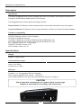
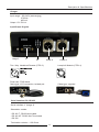
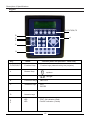
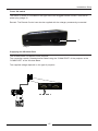
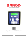
BARCO PROJECTION SYSTEMS
R9840170
R9840171
R9840176
Rugged Remote Control for ELM/SLM Projectors
1
Due to constant research, the information in this manual is subject to change without notice.
Produced by BARCO NV, October 2001.
All rights reserved.
Trademarks are the rights of their respective owners.
BARCO n.v./Projection Systems
Noordlaan 5
B-8520 Kuurne
Belgium
Tel : +32/56/368211
Fax : +32/56/351651
E-mail : [email protected]
Visite Barco at the web : http://www.barco.com
Printed in Belgium
2
Contents
Contents
Safety Instructions ................................................................................................ 4
Notice on Safety ...................................................................................................................................... 4
Installation Instructions ............................................................................................................................ 4
Owner's Record ....................................................................................................................................... 4
FEDERAL COMMUNICATION COMMISSION (FCC STATEMENT) ..................................................... 5
Safety Warning ........................................................................................................................................ 5
On Safety ................................................................................................................................................. 5
On installation .......................................................................................................................................... 6
On servicing ............................................................................................................................................. 6
On cleaning .............................................................................................................................................. 7
On repacking ........................................................................................................................................... 7
General information .............................................................................................. 8
Rugged Remote Control .......................................................................................................................... 8
Upgrade Kits ............................................................................................................................................ 8
Accessories ............................................................................................................................................. 8
Contents ................................................................................................................. 9
Content of the rugged Remote Control Case ......................................................................................... 9
Description .......................................................................................................... 10
Application ............................................................................................................................................. 10
Software Compatibility ........................................................................................................................... 10
Specifications ...................................................................................................... 10
Installation setup ................................................................................................ 14
Power connection .................................................................................................................................. 14
Charging the batteries ........................................................................................................................... 16
Changing the batteries .......................................................................................................................... 17
Configuration setup ............................................................................................ 18
Remote Mode ........................................................................................................................................ 18
Lamp Read Mode .................................................................................................................................. 19
RS232/422 (Software Upgrade) ............................................................................................................ 20
RF Mode ................................................................................................................................................ 22
Menu Set-up ........................................................................................................ 24
Remark concerning display images ...................................................................................................... 24
Display Layout ....................................................................................................................................... 24
General Menu Structure ........................................................................................................................ 24
Internal Menu ......................................................................................................................................... 25
Installation Settings ............................................................................................................................... 25
Lamp Mode Menu .................................................................................................................................. 32
Remote Mode Menu .............................................................................................................................. 33
Additionnal Information ..................................................................................... 34
Messages .............................................................................................................................................. 34
Mechanical Info Rugged Remote Control ........................................................ 35
Dimensions ............................................................................................................................................ 35
3
R5976251 rev. 02
Safety Instructions
Safety Instructions
Notice on Safety
This equipment is built in accordance with the requirements of the international safety standards
EN60950, UL 1950 and CSA C22.2 No.950, which are the safety standards of information
technology equipment including electrical business equipment.
These safety standards impose important requirements on the use of safety critical components,
materials and isolation, in order to protect the user or operator against risk of electric shock and
energy hazard, and having access to live parts.
Safety standards also impose limits to the internal and external temperature rises, radiation
levels, mechanical stability and strength, enclosure construction and protection against the risk of
fire.
Simulated single fault condition testing ensures the safety of the equipment to the user even
when the equipment's normal operation fails.
Installation Instructions
Before operating this equipment please read this manual thoroughly, and retain it for future
reference.
Installation and preliminary adjustments should be performed by qualified BARCO personnel or
by authorized service dealers.
Owner's Record
The part number and serial number are located at the bottom side of the Interface. Record these
numbers in the spaces provided below. Refer to them whenever you call upon your dealer
regarding this product.
PART NUMBER :
SER. NUMBER :
DEALER :
4
Safety Instructions
FEDERAL COMMUNICATION COMMISSION (FCC STATEMENT)
This equipment has been tested and found to comply with the limits of a class A digital device,
pursuant to Part 15 of the FCC Rules. These limits are designed to provide reasonable protection
against harmful interference when the equipment is operated in a commercial environment. This
equipment generates, uses and can radiate radio frequency energy and, if not installed and used in
accordance with the instruction manual, may cause harmful interference to radio communications.
Operation of this equipment in a residential area is likely to cause harmful interference in which case
the user will be required to correct the interference at his own expense.
Note :
The use of shielded cables is required to comply within the limits of Part 15 of FCC rules and
EN55022.
* All the safety and operating instructions should be read before using this unit.
* The safety and operating instructions manual should be retained for future reference.
* All warnings on the equipment and in the documentation manuals should be adhered to.
* All instructions for operating and use of this equipment must be followed precisely.
Safety Warning
TO PREVENT FIRE OR ELECTRICAL SHOCK HAZARD, DO NOT EXPOSE THIS EQUIPMENT
TO RAIN OR MOISTURE
On Safety
1. This product should be operated from an AC power source.
Operating AC power voltage :
100-240VAC 0.4A 47-63 Hz
2. All equipment in the system is equipped with a 2-wire plug.
If you are unable to insert the plug into the outlet, contact your electrician to replace your outlet.
A. EU plug
B. AUS plug
C. UK plug
D. US plug
5
Safety Instructions
3. Do not allow anything to rest on the power cord. Do not locate this product where persons will
walk on the cord.
To disconnect the cord, pull it out by the plug. Never pull the cord itself.
4. If an extension cord is used with this product, make sure that the total of the ampere ratings on
the products plugged into the extension cord does not exceed the extension cord ampere
rating.
5. Never push objects of any kind into this product through cabinet slots as they may touch
dangerous voltage points or short out parts that could result in a risk of fire or electrical shock.
Do not exert extreme forces (shocks) directly on the window of the LCD display.
Never spill liquid of any kind on the product. Should any liquid or solid object fall into the
cabinet, unplug the set and have it checked by qualified service personnel before resuming
operations.
6. Lightning - For added protection for this product during a lightning storm, or when it is left
unattended and unused for long periods of time, unplug it from the wall outlet. This will prevent
damage to the apparatus due to lightning and AC power-line surges.
On installation
For a safe installation, refer to setup-requirements doc/installation doc.
On servicing
Do not attempt to service this product yourself, as opening or removing covers may expose you
to dangerous voltage potentials and risk of electric shock!
Safety indication on the product
The lightning flash with an arrowhead
within a triangle is intended to tell the user
that parts inside this product may cause a
risk of electrical shock to persons.
The exclamation point within a triangle is
intended to tell the user that important
operating and/or servicing instructions are
included in the technical documentation for
this equipment.
6
Safety Instructions
Refer all servicing to qualified service personnel.
Unplug this product from the wall outlet and refer servicing to qualified service personnel
under the following conditions:
1. When the power cord or plug is damaged or frayed.
2. If liquid has been spilled into the equipment.
3. If the product has been exposed to rain or water.
4. If the product does not operate normally when the operating instructions are followed.
Note : Adjust only those controls that are covered by the operating instructions since improper
adjustment of the other controls may result in damage and will often require extensive work by
a qualified technician to restore the product to normal operation.
5. If the product has been dropped or the cabinet has been damaged.
6. If the product exhibits a distinct change in performance, indicating a need for service.
Replacement parts - When replacement parts are required, be sure the service technician has
used original BARCO replacement parts or authorized replacement parts which have the same
characteristics as the original part. Unauthorized substitutions may result in degraded performance and reliability, fire, electric shock or other hazards. Unauthorized substitutions may void
warranty.
Safety check - Upon completion of any service or repairs to this Interface, ask the service
technician to perform safety checks to determine that the product is in proper operating condition.
On cleaning
Unplug this product from the wall outlet before cleaning.
To keep the cabinet looking brand-new, periodically clean it with a soft cloth. Stubborn stains may
be removed with a cloth lightly dampened with mild detergent solution. Never use strong
solvents, such as thinner or benzine, or abrasive cleaners, since these will damage the cabinet.
On repacking
Save the original carton and packing material; they will come in handy if you ever have to ship
your equipment. For maximum protection, repack your set as it was originally packed at the
factory.
Note
Definition
Service personnel: Persons having appropriate training and experience necessary to be aware of
hazards to which they are exposed in performing a task and of measures to minimize the danger
to themselves or other persons
7
General Information
General Information
Rugged Remote Control
This Manual regroups several types of Rugged Remote Control Kits, depending on the type of
rugged remote considered some information in this manual may become superfluous.
R9840170: Wired Rugged Remote
R9840171: Wireless Rugged Remote
R9840176: Wireless Rugged Remote starters Kit (Wireless remote + single channel receiver)
Upgrade Kits
Upgrade to wireless RC: R9840175
Installation Manual Upgrade to Wireless RC: R5976350
Accessories
RCU Base Single (Wireless base): R9840172
Installation Manual RCU Base Single: R5976348
19'' rack mount (for 2 remotes): R9840174
Installation Manual RCU Rack: R5976348
8
Contents
Contents
Contents of the Rugged Remote Control Case
The Rugged Remote Control Case* contains following items:
1.
2.
3.
4.
5.
6.
7.
8.
Boxkit Magik: R593564
Boxkit fit rugged ctr puf: R821134
Rugged Remote Control : R763666
Battery charger: B557208 + EU Plug
supplementary plugs
US: B5572102
UK: B5572101
AUS: B5572104
SUBD9 Male/Male adaptor R821585
Lamp comms cable: Z34980143
Shoulder Strap : B400559
Installation Manual : R5976251
1
2
4.
3.
5.
6.
7.
8.
5
5XJJHG5HP
RWH&RQWUROIRU (/0
6/0'/33URM H
FWRUV
* In case of the R9840176 there is also a separate package containing the Wireless Base
9
Description & Specifications
Description
Application
The Barco Rugged Remote Control enables the control of the Barco ELM and SLM series DLP
Projectors and the Barco 6000 series LCD Projectors.
The Rugged Remote Control allows following functions:
Remote Mode:The Remote Control sends actions to and reads information from the projector
Lamp Read Mode:The Remote Control reads information stored in the lamp information Module.
Software compatibility
G5 SLM: Sofware version V1.05 and higher
R6 SLM: All Software versions
G10 ELM: if fitted with controlller R7637445 (UN G10ELM CPU V2)
R12 ELM: if fitted with controlller R7637446 (UN R12ELM CPU V2)
R6* : Software version V1.11 and higher
G63/G64: Software version V1.31
G65: Software version V1.32
Specifications
Weight
weight: 1.3 kg (2.8 lbs)
Communication range
wired: up to 300m
wireless: up to 100m
Batteries
Supplied: 6 x rechargeable NiCd AA batteries.
Input range Rugged Remote Control : 15-30V DC
Input socket located on the right side of the Remote Control (A: Image 1)
CAUTION
Risk of explosion if the batteries are replaced by an incorrect type
Dispose of used batteries according to the instructions
Image 1
10
A
Description & Specififcations
Charger
Input range : 100-240V (autoranging)
47-63Hz
400 mA
Output: 15V DC/1A
Input/Output Signals
A
image 3
B
CTRL 3
Two Way Hardwired Remote (CTRL 3)
CTRL 4
Lamp Info Module (CTRL 4)
P US H
SLQDVVLJQHPHQW
*1'
'$7$
'$7$
Fixed rate: 57600 baud
Cable type: XLR connection, twisted pair
Cable type: supplied
Serial interface RS 232/422
Serial interface A (image 3)
Selectable modes :
- RS 422 T: RS422 terminated.
- RS 422 NT: RS422 Not Terminated
- RS 232
Termination resistor = 120 Ohms
11
Description & Specififcations
Keypad
F1,F2,F3,F4,F5
B
A
E
F
C
D
Key
Name
F1,F2,F3,F4,F5
Function Keys
A
Browse Keys
Function (when not specified : idem RCU)
Function keys (determined by the projector)
+
up/down
-
-
+
left/right
B
Command Keys
idem RCU
C
Validation keys
EXIT
ENTER
D
Numeric keys
E
F
LED
LED
TEXT ON indicaton (Red)
PAUSE indication (Yellow)
12
Description & Specififcations
Wireless Base
Weight: 0.3 kg (0.6 lbs)
Communication port A
Serial interface C
Selectable modes with switch B :
- RS 422 T: RS422 terminated.
- RS 422 NT: RS422 Not Terminated
- RS 232
In order to set up a communication link the mode setting on the base must match the setting
within the projector
Termination resistor = 120 Ohms
LED D:
when lit: power present
A
B
C
D
image 1
13
Installation Setup
Installation setup
Power Connections
The charger
The charger can be fitted with the 4 supplied power plugs:
1.
2.
3.
1. Australia
2. US/Japan
3. Europe
4. UK
4.
Changing the plug
1. Pull the plug to be changed upwards untill it is completely removed from the charger (Image 1)
2. Place the plug to be mounted on the charger and guide it downwards by using the guiding
slots (Image 1 & 2)
3. Push the plug downwards untill it clicks and is locked into the charger (Image 3)
4. Check if the plug is well locked, it must not stick out of the charger (Image 4).
Image 1
Image 2
Image 3
Image 4
14
Installation Setup
Power ON switch
The ON/OFF switch A is located on the right side of the Rugged Remote Control near the DC
power plug (image 3).
Remark: The Remote Control can also be supplied with the charger permanently connected.
A
image 3
Supplying the Wireless Base
The wireless base is supplied via the projector.
The connection needs a standard serial cable linking the 'COMM PORT' of the projector to the
'COMM PORT' of the Wireless Base.
The supplied voltage depends on the type of projector.
&2003257
&20
3257
15
Installation Setup
Charging the batteries
The batteries are trickle charged whenever the XLR connection with a powered projector is made
or when the charger is connected.
Charging is required whenever the batteries are low, the status (ACT/LOW) of the batteries can
be seen on the main menu (menu 1) or in the diagnosis menu (see " Installation Settings ").
remark: The delivered batteries are not charged.
The batteries may only be used after being charged, it takes about 30 hours to fully
charge the batteries.
NO COMMUNICATION
ADDR=1
BAT=LOW
PRESS <ADJUST> TO ENTER
menu 1
There are two possibilities to charge the batteries:
- To charge the batteries with the supplied charger follow next procedure:
1. Use the supplied charger, with the right plug according the local outlet (see "Power Connec
tions" to adapt the plug), to connect the charger to the wall outlet .
2. Plug the female power connector of the loader into the male connector at the right side of the
remote control.
- The batteries can also be charged via the XLR connection:
This is done whenever the projector is in the standby or ON status, independently of the Remote
Control's status (ON or OFF).
Power Save Mode
When working on batteries (BAT=ACT) the power save mode is enabled if there is no key hit
within 2 minutes, following message is then displayed (menu 2).
NO UPDATE
POWER SAVE MODE
PRESS ANY KEY TO EXIT
menu 2
The Remote Control is automatically switched off after being approximatively 10 minutes in the
Power Save Mode.
Use the ON/OFF switch to reset (OFF-ON) the Remote Control.
16
Installation Setup
Changing the batteries
The expected life of the batteries is about approximatively 1000 charge and discharge cycles.
When replacing the batteries, all batteries should be replaced at the same time.
CAUTION
Risk of explosion if the batteries are replaced by an incorrect type
Dispose of used batteries according to the instructions
To change the batteries follow next procedure:
1.
2.
3.
4.
5.
Turn the remote off and remove all the cables
Turn the locking screw counterclockwise to free the metallic cover (Image 1)
Open the metallic cover (Image 2)
Remove the 6 batteries
Insert the new batteries correctly in the battery compartiment, be sure to install the batteries in
the proper polarity and not to short battery terminals together.
6. Insure that switch A (Image 3) is in the 'CHARGE' position (left position)
7. Close the metallic cover
8. Turn the locking screw clockwise to lock the metallic cover
image 1
A
image 2
image 3
17
Configuration Setup
Configuration Setup
Remote Mode
Performing Remote Control of the projector
The connection of the Rugged Remote Control to a projector uses a standard twisted pair cable
with XLR connectors at each extremity (not supplied).
The baudrate is fixed at 57600 baud.
Image 1 gives an example of a Remote Control connected to a G5 SLM Projector.
Image 1
How to Connect
1. Plug the cable in the Remote connector labeled CTRL3 "Two way hardwired remote".
2. Plug the other extremity in the projector connector with the same label.
Remark: In case of a 6000 series LCD projector XLR remote control is not implemeted.
Refer to "RS232RS422 communication" (page 20) to control the projector.
18
Configuration Setup
Lamp Read Mode
Reading the Lamp
The Lamp Read Mode requires a connection between the lamp unit and the Remote Control
using the supplied lamp cable (Z34980143).
Reading the lamp is only possible for BARCO ELM and SLM projectors.
How to Connect
1. Plug the cable in the remote control connector labeled CTRL4 "Lamp Info Module".
2. Plug the other extremity in the Lamp Unit connector.
WARNING
To avoid burns always let cool down the lamp before handling it .
19
Configuration Setup
RS232/422 Communication
image1
RS 232
- 9600
- 19200
- 38400
- 57600
- 115200
RS 422 T
Different baudrate(baud)settings:
RS 422 NT
The Remote Control allows RS232/422 serial mode communication with the projector.
This is used for software upgrade of the Rugged Remote Control or to perform a remote control
of the projector (instead of using the CTRL3 Two way hardwired remote).
B
See 'Menu Setup' for setting procedure.
To select the different serial modes use switch B (image 1).
RS232/422 remote control
The connection needs the supplied male/male SUBD9 adapter A (image 2) to be placed between
the Remote Control and the projector
A
SLQDVVDGDSWHU$
*1'*1'
image 2
20
Configuration Setup
Software download
The RS232/422 port is always enabled, this makes software upgrading always possible.
For software download follow next procedure:
1 Turn OFF the Remote Control with the main switch
2 Open the battery compartiment (see procedure page 14 )
3 Put switch C (image 2) located in the battery compartiment in the 'DOWNLOAD' position (right
position) to enable downloading via the RS232 port
4 Connect the Remote with your PC using a standard serial cable
5 Turn the Remote on (main switch) and perfom the download
6 Put switch C back in the 'Normal' position and close the battery compartiment
7 Reset (OFF - ON with main switch) the remote control
image 2
C
21
Configuration Setup
RF Mode
In the RF Mode the Wireless Remote Control makes it possible to perform an RF communication
with the projector through the Wireless base.
This is only possible with the Wireless Rugged Remote Control ('General lnformation' page 8) .
How to connect
The connection between the Wireless base and the projector uses a standard serial cable.
The Wireless Rugged Remote can communicate with one or more projectors, this can be done in
two ways:
- One Remote communicates with different projectors each of them using a base (image 1)
- The Remote communicates with different projectors connected in a loop through configuration,
this configurarion uses one base (image 2).
The RF link runs at a fixed baudrate of 57600.
The supply of the base is done through its 'COMM PORT' using a standard serial cable.
&20
3257
56
56
&20
, 1
3257
,1287
image 2
image 1
COMM PORT RS 232/422
22
Configuration Setup
To perform an RF communication following parameters have to be set (see page 29):
RF address
This is a selection of an RF channel for the wireless link.
Any number between 0 and 63 may be chosen.
In the case of multiple wireless links (Image 1 on previous page) each wireless base must have
its own RF address.
Do not uses different receivers with the same address.
Frequency band
Sets the frequency band according to the regulations of the country you are working in.
US/EUROPE: Limits the frequency band according to FCC and ETSI regulations.
FRANCE: Limits the frequency band according to French regulations.
SPAIN: Limits the frequency band according to Spanish regulations.
JAPAN: Limits the frequency band to Japanese regulations.
CANADA: Limits the frequency band to Canadian regulations.
Synchronize base
Downloads the RF address and the Frequency band into the wireless base.
The RF address and the frequency band of the remote and the wireless base have to be the
same in order to have a communication link.
To perform the download the remote has to be connected to the wireless base using a standard
serial cable.
The download is performed through the RS232 communication port.
&2003257 56
&20
3257
image 1
23
Menu Setup
Menu Setup
Remark concerning display images
The bold items do not appear bold on the screen. This is only done to grasp the attention of the
reader.
Display layout
The two upper lines are a copy of the local LCD of the projector when in Remote Mode or the
contents of the Lamp information module when in Lamp Read Mode.
In case of a 6000 series LCD projector these two lines are not displayed.
Line 1
Line 2
Line 3
Line 4
NO COMMUNICATION
BAT=LOW/RF=LOW
ADDR=1
PRESS <ADJUST> TO ENTER
The third line is in most case a status line, showing all kinds of status information of the Remote
Control.
Different status messages:
ADDR=
BAT=ACT
BAT=LOW
RF=ACT
RF=LOW
displays the address of the remote (for example 1).
the remote is working on batteries, there is no supply via external power source.
the battery is running low (see "<Installation Setup" for charging procedure)
the remote is working with wireless communication.
the remote is working with wireless communication but has not etablished a good
communication link.
INTERNAL TEMP TOO HIGH
The third line may also display the actual Internal Menu main title.
The fourth line is a command line, showing possible key commands.
It also displays the item of the Internal menu.
General Menu structure
The Rugged Remote Control's Internal Menu is accessible by pressing the <ADJ> button.
Pressing twice <ADJ> gives access to the projector's Menu or exits the Menu.
MAIN SCREEN
ADJ command not sent to projector
ADJ
RRC INTERNAL MENU
2nd ADJ command sent to projector
ADJ
MAIN SCREEN
Flowchart 1
24
Menu Setup
Internal Menu
The Internal Menu offers some shortcuts to preprogrammed parameters.
RRC INTERNAL MENU
$
CONTRAST
)
BRIGHTNESS
COLOR
)
)
+
TINT
)
PHASE
)
SHARPNESS
FREEZE
HELP
-
MUTE
VOLUME
BALANCE
BASS
TREBLE
INSTAL.SETTINGS
$
Flowchart 2
In the internal Menu the function keys are preprogrammed with the 5 first items (Flowchart 2).
Installation Settings
flowchart 3 gives an overview of the parameters within the 'Installation Settings' menu.
INSTALLATION SETTINGS
$
IDENTIFICATION
+
OPERATION MODE
COMMUNICATION
CHANGE ADDRESS
-
Flowchart 3
DIAGNOSIS
$
Remark: All the menus are of the closed loop type.
25
Menu Setup
Identification menu
IDENTIFICATION MENU
RUGGED REMOTE CONTROL
SOFT VERSION: --.-OPER.MODE:-------+
-
browse with:
COMM.PORT: ------BAUDRATE:--------ADDRESS:---------BATTERY CHARGING:--
Th identification Menu gives an overview of some parameters within the 'Installation Settings'
Menu.
The parameters in the 'Identifcation' Menu are Read Only.
Operation Mode
OPERATION MODE
REMOTE
change with:
(17(5
LAMP READ
The Operation Mode allows to switch between the two Modes:
- Remote Mode
- Lamp Read Mode
See Lamp Mode Menu (p.23) and Remote Mode Menu (p.24) for further detail.
26
Menu Setup
Communication Menu
Flowchart 1 gives an overview of the structure of the Communication Menu
COMMUNICATION MENU
AUTO
XLR
COMM.PORT: AUTO
RS232
RF
9600
19200
+
BAUDRATE:-----
38400
-
57600
115200
RF ADDRESS[0..63]
2
[US/EUROPE]
[FRANCE]
RF OPTIONS
FREQUENCY BAND
[SPAIN]
change with:
(17(5
[JAPAN]
[CANADA]
SYNCHRONIZE BASE
'DVKHG0HQXLWHPVDUHRQO\YLVLEOHLQSUHVHQFHRIWKH:LUHOHVV5HPRWH&RQWURO
Flowchart 1
27
Menu Setup
Selecting the communication port
To enable one of the communication ports handle as follows:
+
1. Browse with
when in the 'Communication Menu'.
2. Select 'comm.port' and confirm with <ENTER>.
3. Select with <ENTER> (Menu 1).
4. Exit the menu with <EXIT> or <ADJ>.
-
NO COMMUNICATION
COMMUNICATION
COM.PORT: [AUTO]
Menu 1
When selecting 'AUTO' following priority is set :
Auto enables the XLR port if it is powered.
if not, RF is enabled else RS232/422 is enabled (see flowchart 1)
XLR
powered?
yes
XLR enabled
no
RF
available?
yes
RF enabled
no
RS232
Flowchart 1
Changing the baudrate
+
1. Browse with
when in the 'Communication Menu'.
2. Select 'Baudrate' and Confirm with < ENTER>.
3. Select one of the different baudrates with < ENTER> (Menu 1).
4. Exit the menu with <EXIT> or <ADJ>.
-
NO COMMUNICATION
COMMUNICATION
BAUDRATE [57600]
Menu 1
Remark: When XLR or RF are enabled, baudrate is fixed at 57600.
28
Menu Setup
RF Options
The RF Options are only available in presence of the Wireless Remote Control version.
RF Options: Changing the RF address
+
1. Browse with
when in the 'RF Options Menu'
2. Select 'RF Address' (Menu 1)
3. Press < ENTER>
4. Use the numeric or the browse keys to change the value of the address
5. Press < ENTER> to confirm
6. The remote displays following message during a few seconds (Menu 2 )
7. Exit the menu with <EXIT> or <ADJ>.
-
NO COMMUNICATION
RF OPTIONS
RF ADDRESS [0..63]
SETTING UP COMMUNICATION
RF OPTIONS
RF ADDRESS [0..63]
2
3
Menu 2
Menu 1
RF Options: Changing the Frequency band
+
1. Browse with
when in the 'RF Options Menu'
2. Select 'Freq. band' (Menu 3)
3. Press < ENTER> to browse
4. The remote displays following message during a few seconds (Menu 4 )
5. Exit the menu with <EXIT> or <ADJ>
-
Menu 3
NO COMMUNICATION
SETTING UP COMMUNICATION
RF OPTIONS
FREQ. BAND [US/EUROPE]
RF OPTIONS
FREQ. BAND[JAPAN]
Menu 4
29
Menu Setup
RF Options: Synchronize base
The wireless base and the remote have to be synchronized (same RF address and freq. band )
To synchronize the base follow next procedure:
1. Connect the 'COMM PORT' of the base to the 'COMM PORT' of the projector using a standard
cable (image 1)
2. Browse with
when in the 'RF Options Menu'
3. Select 'Synchronize base' (Menu 1)
4. Press < ENTER>, the remote displays following message (menu 2)
5. Connect the RS232 port of the wireless base to the RS232 port of the remote using a standard
serial cable (image 1)
6. Press < ENTER>, the remote displays following message during a few seconds (menu 3)
7. Depending on whether the operation succeeded or not one of following messages may be
displayed (menu 4,5)
8. Exit the menu with <EXIT>
+
-
&2003257 56
&20
3257
NO COMMUNICATION
NO UPDATE
RF OPTIONS
SYNCHRONIZE BASE
CONNECT REMOTE TO BASE
AND PRESS <ENTER>
Menu 1
Menu 2
NO UPDATE
NO UPDATE
SYNCHRONIZING BASE
SYNCHRONIZATION FAILED
PRESS <ENTER> TO RETRY
Menu 3
Menu 4
NO UPDATE
BASE SYNCHRONISED
PRESS <EXIT> TO CONTINUE
Menu 5
30
Menu Setup
Change Address
How to change the address:
1. Select 'Change address' in 'Installation settings' (menu 1).
2. Press <ENTER>
+
3. Use numeric keys or
to fill in the new address ( number between 1 and 255 )
4. Confirm with <ENTER>
-
NO COMMUNICATION
CHANGE ADDRESS
ADDRESS
1
menu 1
Shortcut : Use the <ADDR> key for direct access to the address menu. (<ADDR> displays also
the projector's address)
Diagnosis
Flowchart 1 gives an overview of the read only parameters within the 'Diagnosis menu'.
DIAGNOSIS
+
(17(5
+
XLR:ON/OFF
INPUT POWER PORT
DC INPUT:ON/OFF
-
(17(5
+
VOLTAGE:OK/LOW
BATTERY STATUS
CHARGING:ON/OFF
-
(17(5
INTERN.TEMP
TEMPERATURE: OK
(17(5
STATUS
+++
CONTROL
+++
MEMORY
+++
LAMP
++-
+
I 2C DIAGNOSIS
31
-
-
Flowchart 1
Menu Setup
Lamp Mode Menu
Access to the Lamp Read Mode Menu
1. Press <ADJ> to enter the Internal Menu (menu 1).
+
2. Select INSTALLATION SETTINGS by browsing with
3. Select OPERATION MODE by pressing <ENTER> (menu 2).
4. Select the Lamp Read Mode by pressing <ENTER>, menu 4 is displayed.
5. Exit the Internal Menu by pressing <EXIT> or <ADJ>.
-
NO COMMUNICATION
NO COMMUNICATION
INSTALLATION SETTINGS
CONT BRIG COLO TINT PHAS
INSTALLATION SETTINGS
OPERATION MODE
menu 2
menu 1
LAMP
SERIAL NO: -----OPERATION MODE
OPER. MODE [LAMP READ]
NO COMMUNICATION
OPERATION MODE
OPER. MODE [REMOTE]
menu 3
menu 4
Browsing the Lamp Read Mode Menu
To browse the Lamp read Mode Menu when in menu 4 follow next procedure:
+
-
1. Browse the different parameters using the
shown on line 2 (menu 4)
buttons (see flowchart 1), the parameter is
LAMP
line 2
LAMP READ MODE
BAT=ACT
PRESS <ADJUST> TO ENTER
menu 4
+
SERIAL NUMBER
ARTICLE NUMBER
RUN TIME
REMAINING RUN TIME
NUMBER OF STRIKES
-
flowchart 1
32
Menu Setup
Remote Mode Menu
Access to the Remote Mode
1. Press <ADJ> to enter the Internal Menu (menu 1).
+
2. Select INSTALLATION SETTINGS by browsing with
3. Select OPERATION MODE by pressing <ENTER>.
4. Select the Remote Mode by pressing <ENTER>, menu
5. Exit the Internal Menu with <EXIT> or <ADJ>.
-
is displayed.
NO COMMUNICATION
NO COMMUNICATION
INSTALLATION SETTINGS
CONT BRIG COLO TINT PHAS
INSTALLATION SETTINGS
OPERATION MODE
menu 2
menu 1
NO COMMUNICATION
OPERATION MODE
OPER. MODE [REMOTE]
menu 3
Remark: The procedure above is only necessary when changing from Lamp read mode to
Remote Mode.
When powered up the remote control always displays the last selected mode.
Browsing in Remote Mode
To browse the different parameters in Remote Mode use the Rugged Remote Control in the
same way as the standard RCU.
In the remote mode the 2 upper lines are a copy of the projector's display
example using a SLM G5 projector (Menu 4) :
SLM G5 PERFORMER
STANDBY
COMMUNICATION
COM.PORT [XLR]
Copy of projector display
Menu 4
33
Additionnal Information
Additionnal Information
Messages
MESSAGES
POSSIBLE CAUSES
NO COMMUNICATION
-hardware
-parameter mismatch
NO DISPLAY DATA AVAILABLE
-No display on projector
(6*00 series projectors)
RF=LOW
-parameter mismatch
-no supply
NO UPDATE
during synchronisation
update (polling) is interrupted
34
TO CHECK
-connections
-address match proj/RRC
-baudrate match proj/RRC
-
-RF addr match proj/RRC
-Freq band match proj/RRC
perform synchronization if
necessary (page 30 )
-connection (com port)
-
Mechanical Information
Mechanical Information
Dimensions
The external dimensions (mm) of the Rugged Remote Control are illustrated in drawing below:
63
60
189
165
165
45
5
35
Mechanical Information
Mechanical Information
The external dimensions (mm) of the Wireless base are illustrated in drawing below:
129
36
BARCO NV / Projection Systems
Noordlaan 5 B-8520 Kuurne
Belgium
Printed in Belgium
37