1
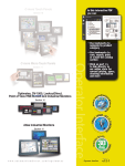
TM
3505 HUTCHINSON ROAD
CUMMING, GA 30040-5860, USA
ATLAS INDUSTRIAL FLAT PANEL PC MONITOR
QUICK INSTALLATION GUIDE - ATM1700/ATM1700T
Description:
ATM1700/ATM1700T
1 - 80 0 - 633 - 0405
NOTE: SEE
HARDWARE USER’S GUIDE, ATM-17-USER,
DOCUMENTATION & DRIVER CD FOR
ADDITIONAL DETAILS. THE USER’S GUIDE IS IN PDF FILE FORMAT AND
REQUIRES DOWNLOADING ADOBE’S FREE ACROBAT READER TO OPEN
AND VIEW.
THE
INCLUDED ON THE SUPPLIED
1. Verify Contents of the Box:
Dimensions:
• Atlas Flat Panel Monitor – ATM1700 or ATM1700T (The “T” at the end of
the part number designates the touch screen option.)
• VGA video cable – 6’ length
• RS-232 Serial touch screen cable (ATM1700T only) – 6’ length
• USB touch screen cable (ATM1700T only) – 2m length
• Mounting clips and screws (qty of 14)
• USB retention bracket and mounting screw (ATM1700T only)
• Documentation and Driver CD
Contents:
Packaging
Material
Atlas
Monitor
Mounting Clips
(qty. 14)
USB Cable
(“T” ver. only)
Agency Approvals:
RS-232 Cable
& hex spacers
(“T” ver. only)
Certifications & Standards
Name
Documentation
& Driver CD
VGA Video
Cable
Atlas
Flat Panel Monitor
1
UL508
E191072
UL1604
CE
E313546
EN 55022-1: Class A,
EN 61000-3-2: Class A,
EN 61000-3-3,
EN 61000-6-2,
IEC 60950-1
C
UL
R
US
w w w. a u to m at i o n d i re c t . c o m
The Atlas ATM1700/ATM1700T is a high performance 17" color TFT
flat panel monitor specifically designed for harsh industrial
environments including Class I & II, Division 2 Hazardous Locations.
The ATM1700/ATM1700T accepts standard analog VGA input or
digital DVI input, and can display all VESA video modes up to 1280 x
1024 at 75 Hz with 16 million colors. An optional 5-wire analog touch
screen (ATM1700T) is available that offers both RS-232 and USB
interface capability. The monitor is housed in a heavy duty steel chassis
with a powder coated machined aluminum bezel. The monitor is
certified to NEMA 4/4X/12 standards, is UL/CUL listed, meets CE
requirements and is RoHS compliant. Panel mounting is simplified
using convenient mounting clips instead of conventional studs. All
monitors are shipped with a power input wiring receptacle, 6’ VGA
cable, 6’ RS-232 cable (ATM1700T only), 2m USB Cable
(ATM1700T only), mounting hardware, this Quick Installation Guide,
and CD-ROM containing Hardware User’s Guide (ATM-17-USER)
and touch screen driver software for Windows 98/NT/2000/XP/Vista.
Mounting Clip Installation:
2. Install Monitor through Enclosure Door or Wall
• Use dimensions as shown in the diagram below to provide a
rectangular mounting cutout in an approved NEMA 4/12 enclosure’s
door or wall.
• Mount the monitor through the enclosure cutout, install and tighten (14)
mounting clips to a torque of 8.0 inch-pounds as shown in the diagram
to the right.
Cutout Dimensions:
CUT AWAY
VIEW
WARNING: Damage can occur by applying excessive torque to the
mounting clips.
WARNING: An operating temperature of 0 to 50 °C (32 to 122 °F)
needs to be maintained for proper operation of the monitor.
3. Connect DVI or VGA Video Cable between Monitor & PC
Cable Connections:
• Connect the included 6’ VGA video cable from the video connector on
the monitor to the video output connector on the host PC being used
with the monitor or use a digital DVI-M cable (sold separately).
• If using a DVI-D cable, then special instructions apply when applying
power; see warning to the right in regards to selecting the video input.
WARNING
Touch Screen is still
active while display
power is off
DISPLAY POWER
NOTE: THE 17” MONITOR WILL PRODUCE THE BEST IMAGE QUALITY IF
PC IS SET FOR A 1280 X 1024 PIXELS @ EITHER 60, OR 75 HZ.
VIDEO MODE.
THE
4. Connect USB or Serial Cable between Monitor & PC
• Applies to ATM1700T touch screen version only.
• Use either the included 6’ RS-232 Serial touch screen cable or the 2m
USB touch screen cable from the appropriate connector on the monitor
to the appropriate connector on the host computer; do not connect
both.
• If using the USB cable, secure the cable using the included USB
retention bracket and screw; consult the Hardware User’s Guide,
ATM-17-USER, on the supplied Documentation and Drive CD for details.
VIDEO CABLE *
TOUCH SCREEN
CABLES *
* NOTE: USE ONE OR THE
OTHER, NOT BOTH.
WARNING
To minimize the risk of potential safety problems, you should follow all applicable local and national codes that regulate the installation
and operation of your equipment. These codes vary from area to area and it is your responsibility to determine which codes should be
followed, and to verify that the equipment, installation, and operation are in compliance with the latest revision of these codes.
Equipment damage or serious injury to personnel can result from the failure to follow all applicable codes and standards. We do not guarantee the
products described in this publication are suitable for your particular application, nor do we assume any responsibility for your product design,
installation, or operation.
If you have any questions concerning the installation or operation of this equipment, or if you need additional information, please call Technical
Support at 770-844-4200.
This publication is based on information that was available at the time it was printed. At Automationdirect.com® we constantly strive to improve
our products and services, so we reserve the right to make changes to the products and/or publications at any time without notice and without
obligation. This publication may also discuss features that may not be available in certain revisions of the product.
2
w w w. a u to m at i o n d i re c t . c o m
1 - 80 0 - 633 - 0405
CUTOUT
5. Connect Power to the Monitor
Power Connections:
• Power source needs to be 100 - 240 VAC, 50/60 Hz, 욷30 Watts.
• See connection diagram below.
• Secure power connector screws to monitor.
• Power should not be applied until all cables are attached and the
monitor is ready to operate.
100 VAC - 240 VAC INPUT (1.0 Amps Min)
TOP VIEW
1 2 3
PIN No.
Definition
1
AC Line Input
2
AC Neutral Return
3
Protective Earth Ground
ADC P.N. ATM-AC-CON or
PHOENIX CONTACT P.N. 1777992
WARNING: Damage can occur if power is not properly connected.
Plug Retention Screws
6. Apply Power to the Monitor & PC
FRONT VIEW
L N
• Press the DISPLAY POWER button on the rear of the monitor to wake the
monitor up. Pressing the DISPLAY POWER button again turns off the
backlight inverter and puts the monitor in a reduced power state but
the touch screen remains active. It is important to note that this switch
does not disconnect power from the monitor. Power is always supplied
to the internal AC/DC power supply, which in turn continually supplies
power to the internal monitor electronics and the optional touch screen
controller.
PE
Power
Connection
Label
LCD Power Button:
Power
Indicator
• Applies to ATM1700T touch screen version only.
• Insert the Documentation and Driver CD into the host PC’s CD drive.
• If the CD does not start automatically with the window shown below
displayed, then go to Start > Run, browse to the CD’s “atlas.exe” file,
open it, and click OK.
• From the Atlas screen, the user can view the Hardware User’s Guide for
the monitor being used, and/or install the touch screen drivers for the
particular PC operating system being used. Before installing the drivers,
please read the Touch Screen Driver Documentation for operating
system details.
• Reboot the PC and restart the monitor to activate the driver.
Display Power
Button
DISPLAY POWER
WARNING
Touch Screen is still
active while display
power is off
WARNING: The monitor does not automatically select a video input
mode. The user must press the “UP (VGA/DVI)” button on the rear
of the monitor to select either VGA or DVI input. If a “No Video”
message appears on the screen, it is also suggested the user try using
the “UP (VGA/DVI)” button to select the active video input.
NOTE:
ONCE YOU HAVE CONNECTED YOUR
PC
AND THE MONITOR,
SELECTED THE VIDEO SOURCE, AND POWERED BOTH UNITS, IT IS
SUGGESTED THAT THE
“SELECT (AUTO ADJ)” BUTTON ON THE REAR
OF THE MONITOR BE PRESSED TO MAXIMIZE THE VIDEO SETTINGS.
OSD Settings Main Menu:
8. Verify Video and Touch Screen Functionality
• Verify the monitor’s video display by running a familiar program.
• If using the touch screen model (ATM1700T), use the touch screen to
navigate by running a familiar program.
RGB
9. Adjust the Monitor OSD Settings as Required
MAIN MENU
BRIGHTNESS/CONTRAST
COLOR
POSITION
SETUP
EXIT
12 8 0 X 10 24
• Press the Select (Auto Adj) control button on the rear of the panel to
initiate an automatic configuration of the screen.
• Although normally not needed, the control buttons on the rear of panel
can be used to make other adjustments to the screen.
• Consult the Hardware User’s Guide, ATM-17-USER, on the supplied
Documentation and Drive CD for detailed usage of the OSD settings.
63.9KHZ/60HZ
Additional Help and Support
• For product support, specifications, installation, and
troubleshooting, a Hardware User’s Guide, ATM-17USER, is included on the supplied Documentation
and Driver CD, or downloadable from the Online
Documentation area of the AutomationDirect Web site.
• For additional technical support and questions, call our Technical
Support team @ 770-844-4200.
10. Installation Complete
3
w w w. a u to m at i o n d i re c t . c o m
1 - 80 0 - 633 - 0405
7. Install the Appropriate Touch Screen Driver
Accessories & Replacement Parts:
Description
ATM-CBL-VGA10
10 ft. 15-pin coaxial VGA cable. Connects any Atlas monitor to a standard VGA card.
ATM-CBL-VGA25
25 ft. 15-pin coaxial VGA cable. Connects any Atlas monitor to a standard VGA card.
ATM-CBL-VGA50
50 ft. 15-pin coaxial VGA cable. Connects any Atlas monitor to a standard VGA card.
ATM-CBL-DV2M
6 ft. (2 meter) DVI (type D) video cable. Connects M1700 and M1900 to a standard DVI-D port. DVI
cables provide a higher bandwidth video interface than the VGA cables.
ATM-CBL-DV3M
10 ft. (3 meter) DVI (type D) video cable. Connects M1700 and M1900 to a standard DVI-D port.
DVI cables provide a higher bandwidth video interface than the VGA cables.
ATM-CBL-10
10 ft. serial communication cable. Connects Atlas monitor to std. 9-pin RS-232 port.
ATM-CBL-25
25 ft. serial communication cable. Connects Atlas monitor to std. 9-pin RS-232 port.
ATM-CBL-50
50 ft. serial communication cable. Connects Atlas monitor to std. 9-pin RS-232 port.
USB-CBL-AB3
3-ft (0.9 meter) Standard USB 2.0 cable with Standard-A plug to Standard-B plug. Suitable for all
USB devices.
USB-CBL-AB6
6-ft (1.8 meter) Standard USB 2.0 cable with Standard-A plug to Standard-B plug. Suitable for all
USB devices.
USB-CBL-AB10
10-ft (3 meter) Standard USB 2.0 cable with Standard-A plug to Standard-B plug. Suitable for all
USB devices.
USB-CBL-AB15
15-ft (4.6 meter) Standard USB 2.0 cable with Standard-A plug to Standard-B plug. Suitable for all
USB devices.
ATM-AC-CON
Replacement Power Wiring Connector for AC Powered Units.
ATM-CLIP
Replacement flat panel mounting clip kit. Package of 16 clips and screws.
ATM-CBL-10
ATM-CBL-25
ATM-CBL-50
USB-CBL-AB3
USB-CBL-AB6
ATM-CBL-VGA10
USB-CBL-AB10
ATM-CBL-VGA25
USB-CBL-AB15
ATM-CBL-VGA50
ATM-AC-CON
ATM-CBL-DV2M
ATM-CLIP
Quick Installation Guide: ATM-17-QIG, Rev. B
ATM-CBL-DV3M
Copyright 2007, Automationdirect.com Incorporated/All Rights Reserved Worldwide
4
w w w. a u to m at i o n d i re c t . c o m
1 - 80 0 - 633 - 0405
Part Number