1
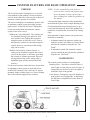
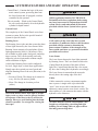
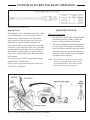
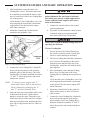
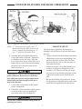
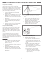
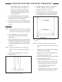
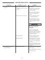
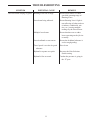
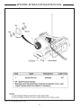
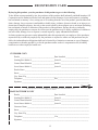
COPYRIGHT 2007 by
ATI Corporation
New Holland, PA 17557 U.S.A.
DISCLAIMER
THE INFORMATION IN THIS MANUAL IS PROVIDED TO PROMOTE THE SAFE USE OF, AND
ASSIST THE OPERATOR IN ACHIEVING THE BEST PERFORMANCE FROM, THE PRODUCTS
DESCRIBED HEREIN WHEN USED FOR THE INTENDED APPLICATION.
Models
Part
Number
Model
Number
Description
3 15-067-000
315-068-000
315-069-000
PL72
PL84
PL96
Box, Grader, Para-Level, Single, 6', Cylinder Only
Box, Grader, Para-Level, Single, 7', Cylinder Only
Box, Grader, Para-Level, Single, 8', Cylinder Only
000-166-407
Kit, Hydraulic, Single MEI/Mikrofyn, Includes Valve Assembly, Hoses, Fittings and Solenoid Cable
000-166-448
Kit, Hydraulic, Single Topcon, Includes System Five Remote, Power and
Solenoid Cable (does not include Sensor Cable)
000-166-483
Kit, Hydraulic, Single Trimble, Includes Valve Assembly, Hoses, and Fittings
000-200-149
Kit, Cables, Topcon System Five, Includes Sensor/Solenoid Cable and Power/
Remote Cable
000-200-148
Kit, Cables, Trimble, Includes Junction Box with Solenoid Cable and Remote, Sensor Cable and Power Cable
315-575-000
Tractor Hitch
NOTE: Optional accessories, Scarifier Assembly, installation and parts manual can be obtained from ATI
Corporation or download from web site, www.level-best.com.
ii
Table of Contents
Models...........................................................................................................................................................ii
Table of Contents..................................................................................................................................iii
Safety Information................................................................................................................................v
Safety Precaution Definitions..................................................................................................................... v
Warranty....................................................................................................................................................vi
List of Illustrations...........................................................................................................................vii
Notes............................................................................................................................................................viii
Systems Features and Basic Operation.......................................................................................1
Purpose....................................................................................................................................................... 1
Components................................................................................................................................................ 1
Control Panel....................................................................................................................................... 2
Rotating Laser..................................................................................................................................... 2
Laser Sensor........................................................................................................................................ 2
Cables.................................................................................................................................................. 2
Hydraulic Valve...................................................................................................................................3
Equipment Set-Up .....................................................................................................................................3
Tractor Grading Box............................................................................................................................ 4
Job Site Set-Up........................................................................................................................................... 5
Set-Up for Level Grading.................................................................................................................... 6
Set-Up for Sloped Grading.................................................................................................................. 6
Benching And Operating............................................................................................................................8
Benching.............................................................................................................................................. 8
Benching with a Rod Eye.................................................................................................................... 8
Operation.............................................................................................................................................9
Troubleshooting...................................................................................................................................10
Specifications and Maintenance..................................................................................................12
Specifications............................................................................................................................................ 12
Dimensions........................................................................................................................................ 12
Maintenance..............................................................................................................................................13
Storage and Transport........................................................................................................................ 13
Cables and Hoses............................................................................................................................... 13
Machine.............................................................................................................................................13
Calibration.........................................................................................................................................13
Service......................................................................................................................................................13
Registration Card.................................................................................................................................15
iii
Table of Contents
(This page left blank)
iv
Safety Information
• Always allow for clearance under the cutting
edge of the machine when tuning the system
or when switching to automatic control.
Insufficient clearance could cause the machine
to lift itself off the ground as its cutting edge
attempts to achieve the programmed slope.
This manual is furnished to you, the owner/operator, as a guide to get the greatest benefit from your
Grading Box. ATI Corporation wants you to be
able to get the most use out of your Grading Box
through safe and efficient operation.
Before attempting to operate the Grading Box,
carefully read all sections of this manual. Be sure
that you thoroughly understand all of the safety
information and operating procedures.
• Never adjust the position of the Laser Sensor
when the system is in automatic control.
• Never perform service work on your machine
or the automatic control system when the
system is in automatic control.
Safety Precaution Definitions
Dangers, Warnings, Cautions, and Notes are
strategically placed throughout this manual to further emphasize the importance of personal safety,
qualifications of operating personnel, and proper
use of the grading box in its intended application.
These precautions supplement and/or complement
the safety information decals affixed to the unit and
include headings that are defined as follows:
• Install all safety panels and guards before
operating your equipment.
• Stay clear of all moving parts when the
machine is in operation.
• Keep all people clear of the machine when it is
running.
• Keep feet and other body parts from under the
cutting edges of the machine at all times.
• Read and comply with all safety recommendations of your Tractor/Skid Steer manufacturer,
as outlined in its operator and service manuals.
Indicates an imminently hazardous situation
which, if not avoided, will result in death or
serious injury.
NOTE: References made to left, right, front, and
rear are those directions viewed from behind the power unit and grading box.
Indicates a potentially hazardous situation or
practice which, if not avoided, could result in
death or serious injury.
NOTE: Some equipment depicted in illustrations
may not reflect exact production model
configurations.
NOTE: All safety, operating, and servicing information reflects current production models
at the time of publication of this manual.
Indicates a potentially hazardous situation or
practice which, if not avoided, will result in
damage to equipment and/or minor injury.
NOTE: ATI Corporation reserves the right to
discontinue models at any time, change
specifications, and improve design without
notice and without incurring obligation on
goods previously purchased and to discontinue supplying any part listed, when the
demand does not warrant production.
NOTE: Indicates an operating procedure, practice.
etc., or portion thereof, which is essential
to highlight.
• Always use caution and safe operating practices when operating this equipment.
• Always set the Automatic/Manual Switch on
the Control Panel to MANUAL before leaving
the operator’s seat or whenever the machine is
not moving.
Warranty
This Laser Grading Box is designed and manufactured to high quality standards. ATI Corporation,
therefore, guarantees this Laser Grading Box to be
free from defect in workmanship and materials for
one (1) year from purchase date. If the machine is
used for rental purposes, the warranty is limited to
ninety (90) days.
Laser Controls, Vendored Components and Control
Valve Parts are warranted separately by their
respective manufacturers.
Does not cover normal wear or failure due to
hydraulic oil contamination.
Misuse, abuse, misapplication, and unauthorized
alterations will void this warranty.
vi
List of Illustrations
Figure 1. Plane of Laser Light with Components of the Automatic Control System.......................................1
Figure 2. Valve Connection Details..................................................................................................................3
Figure 3. Components of the Automatic Control System on a Skid Steer........................................................3
Figure 4. Control Panel Mounting....................................................................................................................4
Figure 5. Components of the Automatic Control System on a Tractor.............................................................5
Figure 6. Method One: Align Rotating Laser with Grade Stakes.....................................................................6
Figure 7. Sight Over Rotating Laser.................................................................................................................6
Figure 8. Grade Stake with Elevation Mark.....................................................................................................7
Figure 9. Method Two: Align Rotating Laser with Grade Stakes.....................................................................7
Figure 10. Lube and Maintenance Chart.........................................................................................................14
vii
Notes
viii
Systems Features and Basic Operation
Purpose
NOTE: It is the responsibility of the dealer or
owner to select, install, and properly operate an automatic control system on this
Laser Grading Box within the guidelines of
this manual.
The Level Best Laser Grading Box is a cost-efficient method for fine grading. Various capacities
sized to fit the skid steer or tractor with a choice of
automatic control systems are available.
Laser-guided depth control provides unmatched
measurement of plane from a single Rotating Laser.
Grade information from a Rotating Laser is processed and automatically directs the grading box’s
hydraulics to maintain the elevation of the cutting
edge.
The Laser Grading Box is intended to operate with
an automatic control system providing accurate
grade control. If desired, the Laser Grading Box
can be operated without an automatic control
system in one of two ways:
Without any Valve/Manifold - The cylinder can
be connected directly to the tractor or skid
steer and the Laser Grading Box operated
using the tractor or skid steer valve. Flow to
the hydraulic cylinder is restricted to improve
control. However, movement of the cutting
edge can be coarse.
Most automatic control systems can operate automatically or manually.
• In manual control, the operator watches an
indicator on the Laser Sensor or Control Panel
and uses the controls to keep the box “On
Grade”.
• In automatic control, the automatic control
system controls the box’s hydraulic cylinder to
keep the box “On Grade”.
With the Valve and No Control System - A
switch can be installed to operate the electric
valve from the tractor or skid steer, providing
fine control of cylinder movement. However,
raising and lowering of the cutting edge is
dependant upon operator attentiveness and
accuracy.
Components
The control system consists of 4 components:
Rotating Laser – Provides a reference Plane of
Laser Light over the job site (refer to Figure 1).
Light plane may be level or set at an angle to
match the slope of the ground.
For the most accurate control and ease of operation,
an automatic control system is used and recommended. This manual is for a skid steer or tractormounted, single cylinder Para-Level Laser Grading
Box with customer-supplied laser controls.
Laser Sensor – Mounted at a specific height on a
mast on the Laser Grading Box, it determines
the difference in depth based on the Plane of
Laser Light.
Figure 1. Plane of Laser Light with Components of the Automatic Control System
Systems Features and Basic Operation
Control Panel – Contains the logic of the automatic control system, processing data from
the Laser Sensor and, if equipped, switches
controlled by the operator.
Use of any laser on a worksite is controlled by
OSHA regulations found at 29 CFR 1926.54.
Be familiar with these regulations before using
any laser beacon used in conjunction with this
system. Review and understand all literature
provided with the Laser System before operating.
Valve Assembly – Wired to the Control Panel,
the valve meters hydraulic oil to the hydraulic
cylinder for depth control.
Control Panel
The complexity of the Control Panel varies from
system to system. Refer to the specific brand of
system for specific details.
Laser protection devices must be provided
to all workers in the area if the laser system
exceeds five (5) milliwatts. Refer to the literature
provided with the system to determine the
power output. If unsure of the strength of the
laser system, anti-laser eye protection should be
provided to all workers.
Rotating Laser
The Rotating Laser is the unit that creates the plane
of laser light detected by the Laser Sensor. Most
Rotating Lasers transmit a focused plane of laser
light approximately 1000 ft. (300 meters). They
are available in single grade, dual grade, and steep
slope versions. They can be quickly and easily
aligned to job site requirements without complicated calculation of angles.
Laser Sensor
The Laser Sensor detects the laser light generated
by Rotating Lasers. The Laser Sensor sends to the
Control Panel the location of the plane of laser
light. The Control Panel then has the valve assembly drive the Grading Box's hydraulics accordingly.
A dual slope Rotating Laser can be configured
for level, single slope, or dual slope applications.
Simply enter the required percent of grade and
align the Rotating Laser to the axis (direction) to be
graded.
The Laser Sensor is mounted on the mast pole
directly above the cutting edge of the box.
• Percent of Grade. The change in elevation for
every 100 feet (30 meters) graded.
Cables
Cables connect the various components together
into a system. A single cable is provided with
“open” wires at one end for attachment to the
automatic control system or an electric switch. The
other end has a 3-pin connector that mates with the
hydraulic valve connector.
• Slope. The change in elevation per foot
(meter).
Never look directly into a laser light or serious
injury to the eye may occur. In general, incidental exposure of the laser to the eye will not do
damage. However, avoid looking into the beam
whenever possible. Use a target for viewing the
laser spot.
All cables must be secured with adequate cable
length to avoid pinching, stretching and tight
bending. Do not clamp cables to pipes or hoses
that may generate high heat.
Systems Features and Basic Operation
Figure 2. Valve Connection Details
Equipment Set-Up
Hydraulic Valve
The hydraulic valve is mounted on the frame of the
Laser Grading Box. It is an electrically-actuated
double-acting, single-section valve. Hoses and
quick-couplers to attach it the tractor’s auxiliary
hydraulics are included with the hydraulic kit.
Skid Steer Grading Box
1. Provide power to the Control Panel from the
skid steer's electrical system. Usually this
involves a direct hookup to the battery.
2. The Laser Grading Box should be positioned
on a level area for attaching to the skid steer.
Start the skid steer and drive up to the attachment plate and secure per the manufacturer’s
directions. The Level Best quick-attach plate
is designed to be universal.
An electrical cable is also provided. One end of the
cable has a 3-pin connector for the valve. The other
is open and can be attached to the Control Panel of
the automatic control system as required. Refer to
Figure 2 for wiring details of the cable and conductor functions.
The valve accepts a 12 VDC proportional current
signal from the Control Panel.
NOTE: If the skid steer’s pins do not fit securely
into the rectangular holes at the base of
the attachment plate, these holes can be
notched larger to accept the pins.
If you require a proportional time or 24 volt valve,
contact ATI Corporation.
Figure 3. Components of the Automatic Control System on a Skid Steer
Systems Features and Basic Operation
3. After installation, ensure that the Laser
Grading Box is level. The loader arms must
be completely lowered and the bucket cylinders set so the tires of the Laser Grading Box
are on the ground.
Cables must be securely fastened and pinch/rubpoints eliminated. Do not fasten to hydraulic
lines which may operate at high temperatures.
Ensure sufficient cable length to allow movement of the machine.
Verify that the Laser Grading Box is level by
observing that the main frame is horizontal
to the ground. Turn the skid steer engine
OFF when connected.
7. Connect the various cables to the control
system components.
4. Mount the Control Panel on the bracket
attached to the hydraulic valve.
8. If possible, set the automatic control system
to manual mode to prevent unintended
movement of the Laser Grading Box.
Always have system in Manual setting when not
operating the skid steer.
Tractor Grading Box
1. Provide power to the Control Panel from
the tractor's electrical system. Usually this
involves a direct hookup to the battery.
2. The Laser Grading Box should be positioned
on a level area for attaching to the tractor.
Start the tractor and back up to the Laser
Grading Box. Attach the unit with the hitch
pins supplied.
Figure 4. Control Panel Mounting
5. Connect the Laser Grading Box’s hydraulic
hoses with quick couplers to the auxiliary
hydraulic ports of the skid steer. The Laser
Grading Box’s hydraulic manifold is marked
“P” and “T” where the pressure and return
(tank) hoses connect.
3. After installation, ensure that the Grading
Box is level. Set the pitch of the Laser
Grading Box by adjusting the top and lower
links.
NOTE: “P” means pressure (supply) and “T”
means tank (return). Refer to the skid steer
Owner’s Manual for identifying the “P”
and “T” Auxiliary Hydraulic Ports.
4. Mount the Control Panel on the right rear
fender of the tractor or other easily accessible location.
6. Insert the mast pole in the holder until it rests
at the bottom of the tube. Tighten the tee
handle to secure the mast. Clamp the Laser
Sensor near the top of the mast so it is higher
than any local obstruction including the skid
steer cab or fall protection devices. (Refer to
Figure 3).
Verify that the Laser Grading Box is level by
observing that the main frame is horizontal
to the ground. Turn the tractor engine OFF
when connected.
5. Connect the Laser Grading Box’s hydraulic
hoses with quick couplers to the tractor
quick couplers. The Laser Grading Box’s
hydraulic manifold is marked “P” and “T”
where the pressure and return (tank) hoses
connect.
Systems Features and Basic Operation
Figure 5. Components of the Automatic Control System on a Tractor
Job Site Set-Up
NOTE: “P” means pressure (supply) and “T”
means tank (return). Refer to the tractor
Owner’s Manual for identifying the “P”
and “T” Auxiliary Hydraulic Ports.
The following are guidelines for setting up a
Rotating Laser for both level job sites and sloped
job sites:
6. Insert the mast pole in the holder until it
rests at the bottom of the tube. Tighten the
tee handle to secure the mast. Clamp the
Laser Sensor near the top of the mast so it is
higher than any local obstruction including
the tractor cab or fall protection devices.
(Refer to Figure 5).
• Choose a location for the Rotating Laser where
obstructions, such as trees and buildings, can
not block the plane of laser light. The Laser
Sensor needs to be able to sense the plane of
laser light at all times.
• Whenever possible, set up the Rotating Laser
and the Laser Sensor at a height above the
machine’s cab. This prevents the cab or rollover structure from blocking the plane of laser
light as the machine moves around the job
sites.
Cables must be securely fastened and pinch/rubpoints eliminated. Do not fasten to hydraulic
lines which may operate at high temperatures.
Ensure sufficient cable length to allow movement of the machine.
• Be sure the Rotating Laser and Laser Sensor
are operating in compatible modes with a head
speed that is recognized by the other device.
7. Connect the various cables to the control
system components.
8. If possible, set the automatic control system
to manual mode to prevent unintended
movement of the Laser Grading Box.
Always have system in Manual setting when not
operating the tractor.
Systems Features and Basic Operation
Set-Up for Level Grading
If the job site is to be level, the set-up of the
Rotating Laser is simple. Since no slope is required
in either axis, the Rotating Laser does not need to
be aligned. The Rotating Laser will provide a level
plane of laser light in all directions.
1. Locate the Rotating Laser following the
guidelines above.
2. Apply power to the Rotating Laser. Level the
Rotating Laser (some Rotating Lasers will
automatically level, others will need manual
adjustment).
Figure 6. Method One: Align Rotating Laser with Grade
Stakes
4. Set the counter on the Rotating Laser for
both axis to 0.0000% (If needed, see the
Rotating Laser Operation Manual).
3. Set the counters for both axis at 0.000% (If
needed, see the Rotating Laser Operation
Manual).
5. Roughly align one of the axis to the grade
stakes by sighting over the top of the
Rotating Laser (Refer to Figure 7).
4. Bench the machine. See the “Benching and
Operating” procedure in this section.
Set-Up for Sloped Grading
If the job site is to be graded for a single or dual
slope, the Rotating Laser requires its axis to be
aligned for the job site. The Rotating Laser will
then provide a plane of laser light at the required
slope(s).
The following procedures are for two typical
examples of job sites requiring sloped grades.
Remember, each job site is unique, so consider the
following methods as guidelines and not as the only
methods possible.
Figure 7. Sight
6. Align the plane of laser light.
a.Set a grade rod with Rod Eye Receiver
on the far grade stake and adjust the rod
until the Rod Eye Receiver indicates “On
Grade.”
Method One:
1. Set a minimum of two grade stakes exactly
in line with one of the axis to be graded
(Refer to Figure 6).
b.On the axis not aligned with the stakes,
enter on the Rotating Laser: 5.000%.
Allow the Rotating Laser to level itself to
this new position, if needed.
2. Place the Rotating Laser in line with the two
grade stakes.
3. Switch on the Rotating Laser. Level the
Rotating Laser (some Rotating Lasers will
automatically level, others will need manual
adjustment).
Over Rotating Laser
c.Check the Rod Eye Receiver again.
• If the Rod Eye Receiver indicates
“On Grade”, the plane of laser light is
aligned correctly.
Systems Features and Basic Operation
4. Roughly align one of the axis to the grade
stakes by sighting over the top of the
Rotating Laser (Refer to Figure 7).
• If the Rod Eye Receiver indicates the
plane of laser light is too high or too
low, have a second person rotate the
Rotating Laser on the tripod in small
steps until the Rod Eye Receiver indicates “On Grade.”
5. Set both the counters on the Rotating Laser
to the required percent of grade (If needed,
see the Rotating Laser Operation Manual).
7. Enter on the Rotating Laser the required
percent of grade for each axis and allow the
Rotating Laser to level itself again.
8. Bench the machine. See the “Benching and
Operating Your Machine” procedure in this
section.
Method Two:
NOTE: This procedure requires that the elevations
of the grade stakes are correct and aligned
to the slope or percent of grade required.
1. Set a minimum of two surveyed grade
stakes. The stakes must have elevation
information.
2. Place the Rotating Laser a few feet (meters)
behind the first grade stake and in line with
one of the far grade stakes (it is not critical
to align the Rotating Laser exactly). (Refer
to Figure 9.)
Figure 9. Method Two: Align Rotating Laser with Grade
Stakes
NOTE: The Grade Rod must be held plumb for
each of the readings taken in the following
steps.
NOTE: Follow the guidelines at the beginning
of this section when placing the Rotating
Laser.
6.
3. Switch on the Rotating Laser. Level the
Rotating Laser.
Establish the H.I. (height of the instrument)
for the plane of laser light.
a.Align the bottom of the Grade Rod to the
mark on the near grade stake.
b.Adjust the Rod Eye Receiver up and down
until it indicates “On Grade.”
c.Adjust the Rod Eye Receiver for any cut
or fill amount indicated by the grade stake.
• If the grade stake shows a cut, extend
the Grade Rod and Rod Eye by the
amount shown as a cut.
• If the grade stake shows a fill, lower the
Rod Eye by the amount shown as fill.
Figure 8. Grade Stake with Elevation Mark
Systems Features and Basic Operation
Benching
7. Align the plane of laser light.
a.Align the bottom of a Grade Rod to the
mark on the far grade stake.
1. Move the machine to an area which is close
to finish grade or, using the manual controls
on the control system, grade a small area
close to finish grade.
b.Check the Rod Eye Receiver.
• If the Rod Eye Receiver indicates
“On Grade,” the plane of laser light is
aligned at the correct slope.
NOTE: Finish grade can be checked several times
during the grade process to “zero” in on
final grade.
• If the Rod Eye Receiver indicates the
plane of laser light is too high or too
low, have a second person rotate the
Rotating Laser on the tripod in small
steps until the Rod Eye Receiver indicates “On Grade.”
2. If equipped, set the automatic control system
to manual.
3. Turn the Laser Sensor and Rotating Laser
ON.
4. If equipped, set the deadband tolerance to
the minimum possible.
NOTE: If it was necessary to rotate the Rotating
Laser a significant amount at the far stake,
then the original reading at the near stake
may be out of tolerance. Check the setting again and make minor adjustments as
required.
NOTE: Use narrow deadband for benching.
5. Adjust the height of the Laser Sensor until it
is “On Grade”. For:
Telescoping Masts, loosen the locking knob
on the mast and raise or lower the Laser
Sensor. Tighten the locking knob when
correct.
8. Bench the machine.
NOTE: If needed, check the elevations on both the
plane of laser light and the grade stake
elevations by setting the bottom of the
Grade Rod at any stake’s grade mark and
checking the Rod Eye Receiver for the “On
Grade” indication.
Non-Telescoping Masts, loosen the mounting knob for the Laser Sensor and raise
or lower the Laser Sensor. Tighten the
mounting knob when correct.
NOTE: Most materials graded must later be
compacted. To compensate for the compacting distance, lower the Laser Sensor.
This raises the cutting edge by the same
distance. The distance the Laser Sensor is
lowered depends on the material.
Benching And Operating
Before benching, the plane of laser light must be
set at its proper slope. Benching is the process of
setting the relationship between the Laser Sensor
and the Rotating Laser or benchmark. Failure to
properly bench the system before grading will
result in an unacceptable grade.
Benching with a Rod Eye
To bench the Laser Sensor follow the process listed
below:
The goal is to have the Laser Grading Box approximately 1/2 full during operation. If, during rough
grading, a lot of material needs to be removed
from a site, the Laser Sensor should be set several
inches higher than finished grade. As material is
removed, the Laser Sensor can be lowered and the
site regraded. This may need to be repeated several
times until finished grade is achieved.
1. Turn on the Rotating Laser. Attach a Rod
Eye to a measuring pole and turn on. Set the
base of the measuring pole on the benchmark
and adjust the measuring pole so the Rod
Eye emits a solid “On Grade” tone (compensate for slab thickness and compaction if
needed).
Systems Features and Basic Operation
2. Find an area to be graded that is close to
specified grade. Start the skid steer or tractor,
engage the auxiliary hydraulics and move
the unit to that location. Manually raise or
lower the Laser Grading Box’s cutting edge
until it is even with the bottom of the measuring pole when the Rod Eye is emitting the
“On Grade” tone or resting on the ground if
already at grade.
• In some situations, the automatic control
system may require a cut deeper than the
machine can handle. The machine may
lose traction, stall the engine, or the wheel
frame will be lifted off the ground to the
maximum stroke of the cylinder as the
cutting edge tries to reach finished grade.
If this occurs, set the Auto/Manual Switch
to MANUAL and use the Raise/Lower
Switch to raise the cutting edge until the
machine can push the material. Make
multiple passes to cut the area to closer to
finished grade and then go back to AUTO
control. This allows the high spots to be
gradually removed.
3. Making sure the automatic control system is
set to manual and the deadband tolerance is
at its minimum, move the Laser Sensor to a
height on the mast pole where it indicates the
beam is in the “On Grade” position and is
unobstructed by any object.
Operation
NOTE: In rough grading situations, the automatic
control system can usually operate as an
“Indicate Only” system and the machine
controlled manually. After the area is rough
graded, return to automatic control.
After the Laser Grading Box is connected and the
automatic control system is calibrated, operation
can begin.
The operational goal is to drive over the area to
be graded with the box 1/2 full of material and the
Control Panel’s Green Light always illuminated.
4. After several passes with the Laser Grading
Box, stop and turn off the skid steer or tractor. Place the base of the measuring pole on
the graded area check grade elevation.
1. When seated in the Operator’s seat, start the
skid steer or tractor and set the automatic
control system to operating in automatic
mode.
5. After a rough grade is achieved, reduce the
deadband tolerance to meet the job tolerance
requirements. With a tighter deadband, the
speed of the skid steer or tractor must be
decreased for optimum finish.
2. If equipped, set the deadband tolerance to a
large value.
NOTE: Most materials graded must later be compacted. To compensate for the compacting distance, lower the Laser Sensor. This
raises the box’s cutting edge by the same
distance. The distance the Laser Sensor is
lowered will depend on the material.
3. Drive the machine forward or reverse (The
Para-Level Grading Box has front and rear
cutting edges). The automatic control system
constantly senses the plane of laser light
to maintain the cutting edge of the box at
the required elevation. Note the following
during operation:
Troubleshooting
Symptom
Laser Grading Box does not raise
or lower.
Laser Grading Box moves in
opposite direction.
Potential Cause
Control Panel not turned on.
Remedy
Apply power.
No hydraulic flow to Laser Grading Box.
Ensure hydraulic control handle
of skid steer or tractor is in
correct position.
Ensure auxiliary hydraulics are
ON or in continuous flow
mode.
Cables not connected correctly.
Refer to the automatic control
system documentation.
Move directional valve spool
manually using the overrides
on the end of the directional valve.
Be sure to stay clear of any
moving parts of the Laser
Grading Box.
If the Laser Grading Box
moves, refer to Electrical
problems. If the Laser Grading
Box does not move, refer to
Hydraulic problems.
Electrical Problems
Refer to the automatic control
system documentation.
Hydraulic problems.
Confirm hydraulic flow through
the manifold and returning to
the power source through the
“T” hose.
Hydraulic flow reversed.
Contact ATI Corporation for help
troubleshooting the hydraulic
manifold.
Confirm the pressure is going in
the “P” port.
Verify control handle is moving in
desired direction.
10
Troubleshooting
Symptom
Box has trouble staying on grade.
Potential Cause
Rotating Laser out of range.
Remedy
Ensure Laser Sensor is within
specified operating range of
Rotating Laser.
Laser beam being reflected.
Ensure Rotating Laser’s light is
not reflecting off other surfaces
(windows, windshields, mirrors, etc.) causing multiple
readings by the Laser Sensor.
Multiple laser beams.
Ensure that there are no other
lasers operating on the job site
or nearby.
Laser deadband set too narrow.
Ensure the deadband tolerance is
set for rough grading.
Travel speed is too fast for grade
tolerance.
Slow down.
Hydraulic response too quick.
Decrease the Gain Selection
Switch setting.
Hydraulic flow reversed.
Confirm the pressure is going in
the “P” port.
11
Specifications and Maintenance
Specifications
Dimensions
Model
Box Width
Overall Width
PL72
72 in.
(183 cm)
74.8 in. (190 cm)
Total Length
Box Capacity, Front
Box Capacity, Rear
Weight
PL84
84 in.
(213 cm)
86.8 in. (220 cm)
PL96
96 in.
(244 cm)
98.8 in. (251 cm)
66 in. (168 cm)
11.5 ft3 (0.33 m3)
7.0 ft3
(0.20 m3)
1530 lbs. (694 kg)
13.4 ft3 (0.38 m3)
8.0 ft3
(0.23 m3)
1590 lbs. (721 kg)
12
15.3 ft3 (0.43 m3)
9.0 ft3 (0.25 m3)
1650 lbs. (739 kg)
Specifications and Maintenance
Maintenance
Calibration
Perform periodic calibration checks of the Rotating
Laser System as outlined in its Operation Manual
to ensure accurate performance.
The rugged and durable automatic control system
is built to last, but as with all equipment, a few
minutes of routine care, maintenance, and cleaning
can extend the life of the system.
Service
Storage and Transport
If the automatic control system is not functioning
properly, the first step is to determine the problem
component. Use the Troubleshooting Chart to
determine possible causes and remedies.
Most often the Laser Grading Box and its hydraulic
controls remain on the machine. However, the
Control Panel, Laser Sensor, Coiled Sensor Cable
and Solenoid Cable should be stored in a safe,
protected place when not in use. Protect the cable
connections by installing any covers supplied.
Cables and Hoses
The automatic control system is a highly sophisticated electronic system. Do not attempt repairs
to the components. Contact your local dealer if
you have any problems.
Check all cables and hoses regularly for signs of
wear and damage. Keep cable connections clean
and free from dirt and corrosion. If a cable has been
damaged, do not attempt to repair. Incorrect or poor
connections can cause damage to your automatic
control system.
When applicable, check the hydraulic hoses. Look
for areas where the hoses could rub against each
other or another object as they expand and contract
under pressure. Check the hydraulic fittings for
tightness.
Machine
Check areas that affect the Automatic Control
system function and accuracy, such as looseness or
play in the cylinders or wear on the box’s cutting
edge. Looseness in the connection to the tractor/
skid steer, such as in the adaptor plate/3-point hitch,
will cause inaccurate depth positioning.
Also check the tractor/skid steer routinely for wear
to its components, such as loader pins and 3-point
linkage, ensuring it is operating properly.
13
Specifications and Maintenance
Figure 10. Lube and Maintenance Chart
14
Registration Card
By buying this product, you, the purchaser of this product, agree to the following:
To the fullest extent permitted by law, the purchaser of this product shall indemnify and hold harmless ATI
Corporation and its authorized dealer from and against claims, damages, losses and expenses, including
but not limited to attorney’s fees, arising out of or resulting from the use of the product, provided that such
claim, damage, loss or expense is attributable to bodily injury, sickness, disease or death, or to injury to or
destruction of tangible property, but only to the extent caused by the negligent acts or omissions (Including
but not limited to misuse or alteration of the product) of the purchaser, anyone directly or indirectly
employed by the purchaser or anyone for whose acts the purchaser may be liable, regardless of whether or
not such claim, damage, loss or expense is caused in part by a party indemnified hereunder.
In claims against any person or entity indemnified under this agreement by an employee of the purchaser,
anyone directly or indirectly employed by the purchaser or anyone for whose acts the purchaser may be
liable, the indemnification obligations shall not be limited by a limitation on amount or type of damages,
compensation or benefits payable by or for the purchaser under worker’s compensation acts, disability
benefit acts or other employee benefit acts.
CUSTOMER COPY
Dealer ____________________________________Date Installed ________________________
Control Panel Model # _______________________Serial # _____________________________
Grading Box Model # ________________________Serial # _____________________________
Laser Sensor Model # ________________________Serial # _____________________________
Dealer Name ___________________________________________________________________
Street _________________________________________________________________________
City, State, Zip _________________________________________________________________
Telephone _________________________________Fax_________________________________
Signature ______________________________________________________________________
DETACH AND MAIL TO ATI CORPORATION • 250 EARLAND DRIVE • NEW HOLLAND, PA 17557
or FAX to (717) 354-2162
MANUFACTURER’S COPY
Dealer ____________________________________Date Installed ________________________
Control Panel Model # _______________________Serial # _____________________________
Grading Box Model # ________________________Serial # _____________________________
Laser Sensor Model # ________________________Serial # _____________________________
Customer Name ________________________________________________________________
Street _________________________________________________________________________
City, State, Zip _________________________________________________________________
Telephone _________________________________ Fax_________________________________
Signature _____________________________________________________________________
15