1
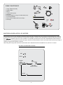
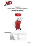
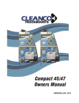
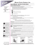
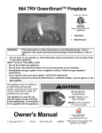
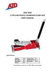
INSTRUCTION MANUAL
S1590, Rev B
ATD-50012
Electric Fuel Pump
LISTED MOTOR
(FPM-12)
Congratulations on purchase of this World Class Electric Fuel Pump!
Elbow
Nozzle
Holder
Pad Lock
Lever
Fuel
Control
Nozzle
This is an Electric Fuel Pump. Pump uses 2 Sintered Powder
Metal gears for suction & is designed for use with Gasoline,
Diesel, E15 Fuel, Kerosene, Bio Diesel (B20) etc. In ideal
laboratory conditions, pump dispenses up to 15 GPM (57 LPM)
at the pump outlet. The actual discharge varies depending on
fuel being used, temperature, Hose Length, power supply etc.
Pump
Outlet
OFF
ON
Swivel
Nut
Motor
Switch
Inside of
Pump
ATD-50012 is a 12V DC Pump
Suction Tube
Hose
12’ x 3/4” I.D.
Rating is marked on the pump motor.
Pump uses an Explosion Proof motor & the motor is UL ,
cUL, ATEX & IECEx listed.
1
California Prop 65 WARNING:
Batteries contain lead and other chemicals known to the State of California to cause cancer, birth defects and other
reproductive harm. Wash hands after handling.
General Safety Warnings:
WARNING: The instructions and warnings contained in this manual should be read and understood before using
or operating this tool. Do not allow anyone to use or operate this tool until they have read this manual and have
developed a thorough understanding of how this tool works. Failure to observe any of the following instructions could
result in severe personal injury to tool user and bystanders, or cause damage to the tool and property. Keep this manual
for future reference.
Note:
The warnings and cautions discussed in this instruction manual cannot cover all possible conditions and
situations that may occur. It must be understood by the operator that common sense and caution are factors which
cannot be built into this product, but must be supplied by the operator.
WARNING: Use safety equipment. Users and bystanders should use safety goggles or safety glasses with side
shields which comply with current national standards, or when needed, a face shield. Use an ANSI approved dust mask or
respirator when working around metal, wood, and chemical dusts and mists. This applies to all persons in the work area.
Also use non-skid safety shoes, hardhat, gloves, dust collection systems, and hearing protection when appropriate.
WARNING:
Keep bystanders and children out of the work area while operating this tool.
WARNING:
Always keep your work area clean, uncluttered, and well lit. Cluttered or dark areas invite accidents
and injuries. DO NOT work on floor surfaces that are slippery.
WARNING:
Do not operate this tool if you are tired or under the influence of alcohol, drugs, or medications that
could affect your ability to use the tool properly.
WARNING:
Dress properly. Do not wear loose clothing or jewelery as they can be caught in moving parts. Wear
restrictive hair covering to contain long hair.
WARNING: Do not reach over or across running machines. Keep proper footing and balance at all times. Nonskid footwear is recommended when working.
2
Lead Acid Battery Safety Warnings:
WARNING:
The instructions and warnings contained in this manual should be read and understood before using
or operating this tool. Do not allow anyone to use or operate this tool until they have read this manual and have
developed a thorough understanding of how this tool works. Failure to observe any of the following instructions could
result in severe personal injury to tool user and bystanders, or cause damage to the tool and property. Keep this manual
for future reference.
CA Prop 65 WARNING:
Batteries contain lead and other chemicals known to the State of California to cause cancer, birth defects and other
reproductive harm. Wash hands after handling.
WARNING:
•
•
•
WORKING AROUND LEAD-ACID BATTERIES MAY BE DANGEROUS.
Lead-acid batteries release explosive gases during normal operation, charging and jump starting.
All lead-acid batteries (car, truck and boat) produce hydrogen gas which may violently explode in the presence of
fire or sparks. Do not smoke, use matches or a cigarette lighter while near batteries. Only work with lead-acid
batteries in a well-ventilated area. Do not handle the battery while wearing vinyl clothing because static
electricity sparks are generated when vinyl clothing is rubbed.
To reduce risk of battery explosion, follow these instructions and those published by the battery manufacturer
and manufacturer of any equipment you intend to use in the vicinity of the battery. Review cautionary markings
on these products and on engine.
EYE PROTECTION:
• User and bystanders should always wear eye protection, appropriate protective clothing and other safety
equipment when working near lead-acid batteries. Do not touch eyes while working on or around lead-acid
batteries.
• IF SPLASHED WITH BATTERY ACID, IMMEDIATELY FLUSH AFFECTED AREA SUCH AS FACE AND PARTICULARLY THE
EYES WITH CLEAN WATER. SEEK MEDICAL ATTENTION AND CONTINUE FLUSHING FACE AND EYES UNTIL
MEDICAL HELP ARRIVES.
WORKING IN ENGINE COMPARTMENT:
• Use extreme caution while working within the engine compartment, because moving parts may cause severe
injury. Read and follow all safety instructions published in the vehicle’s Owner’s Manual.
GENERAL PRECAUTIONS / PERSONAL PRECAUTIONS:
• Never work alone with lead-acid batteries. Make sure that someone is around to give assistance if you need
help.
• Wear complete eye protection and clothing protection. Avoid touching eyes while working near battery.
• In case of battery acid contact with eyes, skin or clothing, always have soap and water near your work area.
• Remove jewelery such as rings, bracelets, necklaces and watches when working around a battery. A lead-acid
battery can produce a short circuit current, which can melt metals and result in a severe burn.
• Do not drop tools or other metal objects on or near the battery as a spark may result, igniting explosive gases.
• Never attempt to jump start a frozen battery.
3
1
PUMP CONSTITUENTS
3
1.
2.
3.
4.
5.
6.
7.
8.
9.
5
5
Pump & Motor Assembly
Nozzle Holder
Elbow
Suction Tube (2 parts)
Bung Nut
Hose Assembly (12’ Long x ¾” ID Anti Static Hose)
Fuel Control Nozzle
Power Cord complete with Fuse & Clamps
PTFE Tape
2
6
4
5
9
8
7
ELECTRICAL INSTALLATION - DC MOTORS
Cable systems and accessories should be installed in positions that prevent them from being subject to mechanical damage, corrosion,
chemical attack, heat and other detrimental environmental conditions. Selection of the wiring system and cable type must consider
these
and where exposure to such conditions are avoidable, protective measures such as minimizing the risk of mechanical
damage by the use of appropriate armoured cable types should be considered. Motor must be connected using a cable incorporating an
earthing or equipotential bonding conductor.
Filed wiring shall comply with requirement stated article 501 in National Electrical Code (NEC) for Class I, Division 1 Location.
ELECTRICAL DIAGRAM FOR DC MOTOR
RED
+
BLACK
-
MOTOR
M
RED
+
+
ON / OFF
TOGGLE SWITCH
BLACK
-
-
4
ASSEMBLY & INSTALLATION
Ensure tank / drum being used is clean & free of welding slag.
Ensure the tank is vented to allow air into the tank as fuel is
being pumped out. Failure to provide a vent will cause priming
problems
1. Wrap around PTFE tape on the following male threaded joints.
This will ensure a leak-proof connection
•
•
•
•
Male Threads on the Elbow
Male Threads on the Fitting ends of the Hose
Male threads between the 2 Suction Tube parts
Male threads on the Suction tube end that fits into the
pump inlet
2. Assemble the
Nozzle Holder with
the pump. In order
to do so, open the
2 bolts on top of
the On / Off Switch.
Remove the bolts
& re-attach along
with the nozzle
holder
3. Now Fasten the
Elbow into the
pump outlet &
hand tighten. Once
you can no longer
hand tighten, take
a wrench & tighten
the elbow by
about ½ a turn.
Elbow
6. Connect the two halves of the Suction Tube. Suction tube
is designed for use with tanks / drums which are 36” (914
mm) deep & has a total
connected length of 34”
(865 mm). In case you
are installing the pump
on a tank that is deeper,
you would have to get a
standard 1” dia. tube with
1” NPT threads on one
end. Suction tubes longer
than 5’ (1.52 m) require a
foot valve (not provided)
at the bottom of the tube
to prevent loss of prime.
For shallower drums, cut
the suction tube to the
desired length. Ensure that
there is about 2” (50 mm)
gap between the bottom
of the tank/drum & inlet of
the suction tube allowing
for easy entry of fuel into
the tube. Now connect the
Suction Tube to the pump
inlet. Hand tighten
7. Lift the Pump from the
motor. Be careful as the
assembly is heavy. Insert
suction tube into the drum
through the 2” opening on
the drum. Use the Swivel
Nut mounted at the pump
inlet to fasten onto the
Bung Nut. Hand tighten
Pump Outlet
Pump Inlet
4. Take the Bung Nut
& fasten it onto
the 2” opening
on the Drum/
Tank. Bung Nut
has a large 2”
thread & a small
1-1/2” thread. 2”
thread goes into
the drum/ tank,
whereas the 1-1/2” thread is for connecting bung to the pump
8. Take the Fuel being dispensed & pour it into the pump outlet,
until completely filled. This will ensure that the gear chamber
stays lubricated & makes it easier for the pump to prime
9. Take the Hose
Assembly & connect
the threaded end
onto the Elbow at
the pump outlet.
Hose has a hex
nut at the threaded
end which can be
tightened to the
elbow using a wrench
5. In case the Bung Nut does not fit onto your drum/ tank, use a
Drum Bung Converter. Note that bung supplied with the pump
10. Connect the other end of the Hose to the Fuel Control Nozzle
has 2” Pipe threads
11. Connect Power cord to source of power & switch it ON
5
12. The pump is now
ready for use
4. In less than 10 seconds, the pump will be primed & fuel will
start dispensing from the Nozzle
5. Dispensing Action can be stopped by closing the Nozzle, with
the pump still ON. This however must not be done for more
than 5 minutes.DO NOT operate the pump for more than 30
minutes continuously in 1 hour
6. It is best practice to Switch Lever in the OFF position to stop
dispensing
PRIMING
All pump models using the supplied 34” (865mm) suction tube
should prime within 10 seconds after pump is turned on.
Pumps installed at a height upto 5’ (1.52 m) may have difficulty
in priming. Follow the procedure below to initiate priming. Pumps
installed at a suction height above 5’ (1.52m) may have difficulty
in holding prime. It is recommended that a foot valve with ball
check (not supplied with the pump) be added to the bottom of the
suction tube to maintain prime
1. Remove the Elbow from the pump outlet
2. Pour fuel being pumped into the pump outlet until completely
filled
3. Re-assemble the Elbow back into the pump outlet & turn the
pump on. Pump should get primed in less than 10 seconds
4. If pump still does not gain prime, check for any major leaks
in the system. If no leaks are found , then the pump is
mechanically defective & should be reported back to your
Distributor
PUMP OPERATION
7. The pump must never be run dry (no media in the drum) as
that can possibly cause irreparable damage to the motor
8. Once Dispensing is completed, switch off the Lever &
disconnect power supply to the pump
9. Store the Nozzle Back into the Nozzle Holder
WARNING
Do not use curb pump auto nozzle with this pump. Contact your
distributor for auto nozzles for use with electric fuel pumps
MAINTENANCE
1. Clean Inlet Strainer after every 50 hours of operation
2. Inlet strainer is easily accessible without having to disassemble the pump. Strainer is installed just above the pump
inlet & can be accessed by removing the 4 bolts on the side of
the pump holding the Strainer cover
3. Remove & clean strainer
1. Remove Nozzle
from the Nozzle
Holder. The On\
Off switch can be
Switched ON only
once the nozzle is
removed from the
nozzle holder
4. If strainer is excessively dirty, clean tank to protect pump and
the equipment being fuelled
5. After cleaning strainer, replace strainer & cover. Make sure
cover seal is in place
2. Nozzle should be facing the container into which Fuel is to be
dispensed
3. Pump On/Off
Switch Lever is
located under the
nozzle holder. Move
switch lever ON &
simultaneously open
the Nozzle
Strainer
OFF
ON
Pump in ON Position
6
PARTS DRAWING FOR ATD-50012 (FPM-12)
PUMP ASSEMBLY
22
23
24
4
19
25
18
20 21
17
7
8
10
11
26
16
15A
27
29
15
31
32
14
1
2
3
4
5
6
30
33
12
13
28
35
34
36
37
9
38
HOSE, SUCTION TUBE, POWER CABLE & FUEL CONTROL NOZZLE ASSEMBLY
40
41
42
7
43
39
PARTS LIST FOR ATD-50012 (FPM-12)
ITEM#
ORDERING PART# MFG PART#
DESCRIPTION
01
PRT50012-01
THREAD FORMING BOLT M4
02
PRT50012-02
CVR/STNR/FPM/12
COVER (STRAINER)
03
PRT50012-03-16
FPM/KIT/SK
SEAL KIT (INCLUDED 3, 7, 15 & 16)
04
ATD-50005
SVE/FPM/12
STRAINER
05
PRT50012-05
TFB/M8/FPM/12
THREAD FORMING BOLT M8
06
PRT50012-06
CVR/HSG/FPM/12
HOUSING COVER
07
PRT50012-03-16
FPM/KIT/SK
SEAL KIT (INCLUDES 3, 7, 15 & 16)
08
PRT50012-08-09
FPM/KIT/GK
GEAR KIT (INCLUDES 8 & 9)
09
PRT50012-08-09
FPM/KIT/GK
GEAR KIT (INCLUDES 8 & 9)
10
PRT50012-10
SFT/GEAR/FPM/12
SHAFT (GEAR)
11
PRT50012-11
HSG/FPM/12
HOUSING (MACHINED)
12
PRT50012-12
FTNG/BNG/FPM/12
FITTING (BUNG)
13
PRT50012-13
NUT/BNG/FPM/12
SWIVEL NUT
14
PRT50012-14
ADP/BNG/FPM/12
BUNG ADAPTOR
15
PRT50012-03-16
FPM/KIT/SK
SEAL KIT (INCLUDED 3, 7, 15 & 16)
PRT50012-15
CCL/FPM
CIRCLIP
16
PRT50012-03-16
FPM/KIT/SK
SEAL KIT (INCLUDED 3, 7, 15 & 16)
17
PRT50012-17
VLV/FPM/12
BYPASS VALVE
18
PRT50012-18
SPR/VLV/FPM/12
SPRING (BYPASS VALVE)
19
PRT50012-19
EW/3-4/N/FPM/12
ELBOW
20
PRT50012-20
ASCR/M6/FPM/12
THREAD FORMING BOLT M6
21
PRT50012-21
MOT/FPM/12
MOTOR, 12V DC
22
PRT50012-22
TFB/M8/FPM/12
23
N/A
N/A
THREAD FORMING BOLT M4
ELECTRICAL COVER
24
N/A
N/A
DRIVE SCREW U TYPE
25
N/A
N/A
LABEL
26
N/A
N/A
ELECTRICAL HOUSING (M/C)
27
PRT50012-27-39
FPM/KIT/SA/DC
SWITCH ASSEMBLY KIT FOR DC PUMPS
( INC LUDES 27, 28, 29, 30, 31, 32, 33, 35, 36, 37, 38 & 39)
28
PRT50012-27-39
FPM/KIT/SA/DC
SWITCH ASSEMBLY KIT FOR DC PUMPS
( INC LUDES 27, 28, 29, 30, 31, 32, 33, 35, 36, 37, 38 & 39)
29
PRT50012-27-39
FPM/KIT/SA/DC
SWITCH ASSEMBLY KIT FOR DC PUMPS
( INC LUDES 27, 28, 29, 30, 31, 32, 33, 35, 36, 37, 38 & 39)
30
PRT50012-27-39
FPM/KIT/SA/DC
SWITCH ASSEMBLY KIT FOR DC PUMPS
( INC LUDES 27, 28, 29, 30, 31, 32, 33, 35, 36, 37, 38 & 39)
31
PRT50012-27-39
FPM/KIT/SA/DC
SWITCH ASSEMBLY KIT FOR DC PUMPS
( INC LUDES 27, 28, 29, 30, 31, 32, 33, 35, 36, 37, 38 & 39)
32
PRT50012-27-39
FPM/KIT/SA/DC
SWITCH ASSEMBLY KIT FOR DC PUMPS
( INC LUDES 27, 28, 29, 30, 31, 32, 33, 35, 36, 37, 38 & 39)
33
PRT50012-27-39
FPM/KIT/SA/DC
SWITCH ASSEMBLY KIT FOR DC PUMPS
( INC LUDES 27, 28, 29, 30, 31, 32, 33, 35, 36, 37, 38 & 39)
34
PRT50012-34
TFB/M6/25/FPM/12
THREAD FORMING BOLT M6
35
PRT50012-27-39
FPM/KIT/SA/DC
SWITCH ASSEMBLY KIT FOR DC PUMPS
( INC LUDES 27, 28, 29, 30, 31, 32, 33, 35, 36, 37, 38 & 39)
36
PRT50012-27-39
FPM/KIT/SA/DC
SWITCH ASSEMBLY KIT FOR DC PUMPS
( INC LUDES 27, 28, 29, 30, 31, 32, 33, 35, 36, 37, 38 & 39)
37
PRT50012-27-39
FPM/KIT/SA/DC
SWITCH ASSEMBLY KIT FOR DC PUMPS
( INC LUDES 27, 28, 29, 30, 31, 32, 33, 35, 36, 37, 38 & 39)
38
PRT50012-27-39
FPM/KIT/SA/DC
SWITCH ASSEMBLY KIT FOR DC PUMPS
( INC LUDES 27, 28, 29, 30, 31, 32, 33, 35, 36, 37, 38 & 39)
39
PRT50012-27-39
FPM/KIT/SA/DC
SWITCH ASSEMBLY KIT FOR DC PUMPS
( INC LUDES 27, 28, 29, 30, 31, 32, 33, 35, 36, 37, 38 & 39)
40
PRT50012-40
FPM/2R/N
SUCTION TUBE
41
PRT50012-41
SA/HOS/FPM/12
HOSE ASSEMBLY
15A
TFB/M4/10/FPM/12
42
ATD-50007
SA/FCN/S/3-4/FPM/N MANUAL FUEL CONTROL NOZZLE
43
PRT50012-43
FPM/KIT/PC
POWER CABLE ASSY KIT
Optional Accessories Available (Not Shown On Parts List):
ATD-50002 - Fuel Tank Filter and Replacement Elements
ATD-50003 - 10 micron filter element for above
ATD-50004 - 10 micron water block filter element for above
ATD-50008 - Automatic Fuel Control Nozzle
8
QTY
4
1
1
1
4
1
1
2
1
2
1
1
1
1
1
1
1
1
1
1
9
1
1
1
4
1
1
1
1
1
1
1
1
1
4
1
1
1
1
1
1
1
1
1
ATD-50012 (FPM-12) PUMP SPECIFICATION
ATD-50012 (FPM-12)
Description
Heavy Duty 12V DC
Flow Rate*
Up to 15 GPM
(57 LPM)
Explosion Proof
Motor
1/7 HP
12V DC
Amp draw from
Battery
12 Amp
Internal Bypass
Valve
Yes
Suction Pipe
2 pc threaded
Hose
¾” x 12’
Anti Static Hose
Tank Adaptor
2” Threaded
Inlet
1” NPT
Outlet
¾” NPT
Dispensing Nozzle
¾” Manual
with Swivel
Battery Cable
(2 wire)
15’
* measured in lab conditions at pump outlet using Diesel with vehicle engine switched on
WETTED COMPONENTS
Aluminium, Steel, Cast Iron, Nylon, NBR, Zinc, Viton, Polypropylene
RECOMMENDED USE
Gasoline, Diesel, E15 Fuel, Kerosene, Bio Diesel (B20)
9
ATD-50012 (FPM-12) TROUBLESHOOTING
PROBLEM
CAUSE
SOLUTION
Motor rotation wrong.
Check wiring instructions for possible problems
Missing relief valve o-ring seal (16)
Remove gear cover (6), inspect seal, replace if missing or damaged
Sheared drive key (9)
Remove cover (6) and inspect key, replace if worn or sheared
Dirt under by-pass valve (17) or seal (16)
Remove cover (6) and inspect, clean or replace if damaged
Strainer seal (3) leaking
Inspect and replace if damaged
Suction height too high to prime
See Priming Pump, page 5
Worn or damaged gears (8)
Remove cover (6) and inspect gears. Replace if worn or damaged
Motor runs but
pump will not prime Fuel level low
Cover seal (7) damaged
R
Replace if worn or damaged
Inlet strainer (4) clogged
Remove and clean or replace
Air leak in suction tube (40)
Inspect all joints in suction tube. Make sure all joints in suction tube are sealed
and that there are no cracks from over-tightening
-
Air lock in system
Unit pumps but
Motor stalls when
nozzle is closed
Fuel leaking in
motor mount
Motor does not run at proper speed
Check electric connections. Check supply voltage for proper voltage level
Curb Pump Auto Nozzle used
Change to Auto Nozzle for use with Electric Fuel Pumps
Clogged inlet strainer (4)
Clean or replace
Air leak in suction tube (40)
Check to make sure all joints in suction tube are sealed and that there are no
cracks
Suction tube (40) too close to tank bottom
Suction tube must have a 2 in. (50 mm) minimum clearance
Tank empty
R
Tank not vented
Tank must be vented to atmosphere
Worn or damaged gears (8)
Remove cover (6) and inspect gears. Replace if worn or damaged
Damaged motor (21)
Replace motor
Clogged suction tube (40), hose (41) or
nozzle (42)
Inspect and clean
Curb Pump Auto Nozzle used
Change to Auto Nozzle for use with Electric Fuel Pumps
Bypass relief valve (17) stuck
Inspect relief valve, making sure poppet is free. Replace if damaged
Low supply voltage
Check supply voltage
Gears (8) damaged and binding
Inspect gears. Gears should turn freely. Replace if damaged
Faulty motor (21)
Replace motor
Faulty or damaged motor shaft seal (15)
Replace shaft seal
Operating pump extended time with nozzle Do not exceed 5 minutes of operation with nozzle closed
closed
Motor shaft worn
Replace motor if shaft has worn in seal area
Gears (8) binding
Check to make sure gears turn freely on shaft
Operating pump extended time with nozzle Do not exceed 5 minutes of operation with nozzle closed
closed
Motor overheating
Switch will not turn
pump on
Clogged inlet strainer (4)
Clean or replace, see Maintenance, page 5
Clogged suction tube (40), hose (41) or
nozzle (42)
Inspect and clean if required
Operating pump more than 30 minutes
continuous duty
Limit operation to 30 minutes per hour
Blown fuse
Replace fuse. 30 amp automotive fuse
Electrical problem
Check that supply voltage is proper and getting to pump
Defective switch (27)
Check and replace if defective
Mechanical problem
Check switch actuator cam. Cam should be actuating the switch
Damaged or defective motor (21)
Check motor, replace if damaged or defective
10