1
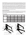
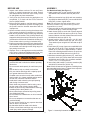
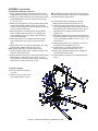
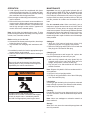
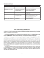
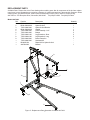
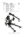
Heavy Duty
Engine Cranes
Operating Instructions & Parts Manual
Capacity
2 Ton
2 Ton
Model Number
Atd-7484
Atd-7485 (Foldable Legs)
Model Atd-7484
Model Atd-7485
Atd Tools Inc.
160 Enterprise Drive, Wentzville, MO 63385
Printed in China
ATD7484-M2 rev 09/09
Save these instructions. For your safety, read and understand the information contained within. The owner and
operator shall have an understanding of this product and safe operating procedures before attempting to use this
product. Instructions and Safety information shall be conveyed in the operators native language before use of this
product is authorized. Make certain that the operator thoroughly understands the inherent dangers associated with
the use and misuse of the product. If any doubt exits as to the safe and proper use of this product as outlined in this
factory authorized manual, remove from service until which time it is clear. Inspect before each use. Do not use
if broken, bent, cracked or otherwise damaged parts are noted. If the crane has been or suspected to have been
subjected to a shock load, discontinue use until checked out by an authorized factory service center. Owners and
operators of this equipment shall be aware that the use and subsequent repair of this equipment may require special
training and knowledge. It is recommended that an annual inspection be done by qualified personnel and that any
missing or damaged parts, decals, warning / safety labels or signs be replaced with factory authorized replacement
parts only. Any crane that appears to be damaged in any way, is worn or operated abnormally should be removed
from service immediately until such time as repairs can be made.
PRODUCT DESCRIPTION
Atd Tools Engine Cranes are designed to safely lift and lower rated capacity engines. It is an aid in the removal and
installation of automotive and light truck engines. Welded steel tube construction, heavy duty chains and safety
hooks, steel casters and wheels along with compliance with the latest ASME / ANSI - PALD standards ensure safety,
strength and stability. Model Atd-7485 is a foldable, space saver design. Each has air actuated option.
SPECIFICATIONS
Model
Atd-7484
Atd-7485
Boom
Position
Capacity
Min. Hook
Height
Max. Hook
Height
Boom Length
1
2 Ton
18-3/8"
69-1/4"
48-3/4"
2
1-1/2 Ton
14"
75-1/4"
57-3/4"
3
1 Ton
9-1/4"
81-1/4"
66-3/4"
4
1/2 Ton
5"
86-1/2"
76-3/4"
1
2 Ton
0"
59-1/4"
48-5/8"
2
1-1/2 Ton
0"
63"
55-5/8"
3
1 Ton
0"
66-5/8"
62-7/8"
4
1/2 Ton
0"
70-1/2"
69-7/8"
Upright
Boom Extension
Braces
Base
Rear Extension Legs
Rear Caster
Boom Extension
Upright
Braces
Hydraulic
Unit (jack)
Hydraulic
Unit (jack)
Handle
Base
Hook
Hook
Middle
Wheels
Caster
Handle
Front Extension Legs
Boom
Crane
Handle
Boom
Front Caster
Figure 1- Model Atd-7484 Components
2
Front Wheel
Front Legs
Figure 2- Model Atd-7485 Components
BEFORE USE
ASSEMBLY
For Model Atd-7484: (See Figure 1)
1. Attach casters (#15) to rear extension legs (#24)
with M8x20 bolts, washers and nuts (#29, 33 &
34).
2. Slide front extension legs (#14) and rear extension
legs (#24) into base frame (#11), secure with M12x25
bolts (#13) in frame, tighten bolts.
Note: Do not tighten any bolts unless told to. Never
1. Inspect crane before each use. Do not use if bent,
broken or cracked components are noted. Ensure
that casters/wheels and boom move freely. Check
for and tighten any loose assemblies.
2. Verify that the product and the application are
compatible, if in doubt call Atd Tools Technical
Service (636)272-9050.
3. Before using this product, read the owner's manual
completely and familiarize yourself thoroughly with
the product and the hazards associated with its
improper use.
3. Open the release valve by turning the release valve
lever counter-clockwise (no more than 1/2 full turn).
4. With ram fully lowered, remove oil filler plug and pump
handle 6 to 8 full strokes. This will help release any
trapped air within the reservoir. Ensure the oil level is
just below the oil filler hole. Reinstall the oil filler plug.
Close release valve by turning it clockwise firmly.
5. Check to ensure that crane rolls freely, that the pump
and release valve operate smoothly. Raise and lower
the unloaded crane throughout the lifting range before putting into service.
6. Replace worn or damaged parts and assemblies
with Factory Authorized Replacement Parts only.
Lubricate as instructed in Maintenance Section.
extend beyond mark on leg. Extend each leg extension
equal distance from frame.
3. Place post (#2) on the base frame and secure with
M12x25 bolts (#13). Leave bolts finger tight.
4. Attach braces (#18) on each side of post at top and
secure with M12x100 bolt and nut (#4 & 19). Place
bottom of braces on inside of base frame secure with
M12x90 bolts and nuts (#31 & 19).
5. Attach bracket (#32) to hydraulic unit (#1) with
M10x30 bolts, washers and nuts (#6, 25 & 26).
Then attach to post using M16x75 bolt and nut (#10
& 12).
6. Place boom (#7) on top of post, secure with M20x120
bolt and nut (#3 & 20). Pump hydraulic unit using
handle (# 21) until ram is approximately 2" above.
Place front mounting bracket on boom, on top of ram
and secure with M16x90 bolt and nut (#9 & 12).
7. Slide boom extension (#8) to boom (#7), make sure
the slot for chain (#17) faces down and secure with
M16x90 bolt and nut (#9 & 12). 4 positions available:
1/2 ton, 1 ton, 1 1/2 ton and 2 ton.
8. Insert chain and hook(#17) to boom extension (#8)
with M12x75 bolt and nut (# 30 & 19).
Note: Check all fasteners for tightness, including those
pre-assembled at the factory. Tighten where required.
Do not load beyond rated capacity.
! WARNING
• Study, understand, and follow all instructions
provided with and on this device before operating
this device.
• Do not exceed rated capacity for each boom position.
• Use the device only on a hard, level surface.
• Only use chains and slings with a capacity equal
to or greater than that of the crane.
• If loaded crane must be moved, make certain that
load is stable, is in lowest possible position and is
moved over a smooth, hard level surface.
• Avoid shock loads caused by the rapid opening
and closing of release valve.
• Shock loads may cause the load to swing, causing the crane to flip violently, bend or break.
• Ensure the boom is fully lowered before checking
or adding fluid to the hydraulic unit.
• Never extend boom extension beyond leg extension (Model Atd-7484).
• Do not stand over loaded boom nor in its intended
line of travel.
• Do not use adapters or accessories that are not
provided initially.
• Do not use the device for any purpose other than
that for which it is intended.
• No alterations shall be made to this device.
• Failure to heed these markings may result in personal injury and/or property damage.
3
Figure 3 - Assembly Illustration for Model Atd-7484
ASSEMBLY (continued)
For Model Atd-7485 (see Figure 2):
1. Attach caster assembly (# 23) to base frame (# 24)
using M8x16 bolts, washers and nuts (# 14, 21 & 22).
2. Install 3.5 " middle wheels (# 33) to base frame (# 24)
using M8x60 bolts, rod cover, washers and nuts (#
31, 32, 22 & 21).
3. Attach two front legs (# 27 & 35) to base frame (# 24)
using M16x85 bolts, washers and nuts (# 43 & 9).
Then secure the legs with stop bar and pin (#25 & 34)
to the front hole of the legs.
4. Attach upright (# 18) to base frame using M12x80
bolts, washers and nuts (# 20 & 10). Upright must
lean towards the rear of the base frame as shown.
Leave nuts finger tight.
5. Attach braces (# 17) to upright(# 18) with M12x80
bolt, washer and nut (# 13 & 2). Leave nut finger
tight.
6. Attach braces (#17 to inside of base frame (24) using
M12x35 bolts, washers and nuts (# 20 & 2).
Note: Braces assemble to inside of base frame.
7. Tighten upright to base frame, braces to upright, and
braces to base frame bolts.
8. Attach hydraulic unit (# 41) to the bracket (# 39) using
M10x30 bolts, washers and nuts ( # 38, 37 & 36).
Then position to mounting ears on post, attach using
M16x75 bolt, washer and nut (# 10 & 9).
Note: Handle of hydraulic unit must face the front of
the base frame as shown. Tighten nut. Lean hydraulic
unit assembly back against post.
9. Connect boom (# 8) to upright (# 18) using
M20x100 bolt, washer and nut (# 12 & 11).
10. Hold boom and pivot hydraulic unit out away
from upright and position ram between mounting
brackets on boom. Attach hydraulic unit to boom
with M16x75 bolt, washer and nut (# 10 & 9).
Tighten nuts.
11. Slide boom extension (# 4) into boom and secure
in retracted position using M12x70 bolt and nut (#
7 & 2). 4 positions available: 1/2 ton, 1 ton, 1 1/2
ton and 2 ton.
12. Slide square washer (# 5) into boom, sesure using M8x16 bolt and washer (# 6, 22)
13. Insert hook (# 1) to boom extension using
M12x60 bolt, washer and nut (# 3 & 2).
14. Attach legs support bracket (# 19) to upright (#
18) with M6x10 bolts (# 42).
15. Attach handle to upright (# 18) with M8x16 bolts
(# 14).
To fold for storage:
a. Remove stop bar and pin (#
25 & 34).
b. Raise leg until it leans on the
legs support bracket (# 19).
Figure 4 - Assembly Illustration for Model Atd-7485
4
OPERATION
MAINTENANCE
Important: Use only a good grade hydraulic jack oil.
We recommend Mobil DTE 13M or equivalent. Avoid
mixing different types of fluid and NEVER use brake
fluid, turbine oil, transmission fluid, motor oil or glycerin.
Improper fluid can cause premature failure of the jack
and the potential for sudden and immediate loss of
load.
1. Load capacity should be coordinated with boom
extension and legs extension. For model Atd-7484,
do not extend boom extension beyond the marking
that coordinate with the legs extension.
2. Secure engine to chain/sling hook assembly, ensure
load is centered.
3. Follow vehicle service manual recommendations to
remove engine. When ready to remove engine, turn
release valve clockwise until firm. Pump handle until
load is high enough to clear vehicle. (squeeze lift
control valve for air actuated option)
For air actuated units: When used daily, pour a
teaspoon of proper lubricant into the air inlet of the lift
control valve. Connect valve to air supply and squeeze
valve lever to operate. This will evenly distribute lubricant
and properly prepare the hydraulic power unit for use.
Periodically check for leaks at air connections. Use
thread compound to repair. Avoid the use of thread tape
when possible.
Note: Avoid rolling the loaded engine crane. To help
position an engine stand if necessary, move only across
smooth, level, seamless surfaces.
Before moving ensure the load:
a. is lowered to the lowest practical position, but always
below the center of gravity.
b. is prevented from swinging and inadvertent shifting.
Adding oil
1. With ram fully lowered and pump piston fully
depressed, set jack in its upright, level position.
2. Remove oil filler plug and fill until oil is level with the
filler plug hole. Re-install oil filler plug.
4. Immediately transfer the load to appropriate engine
support device (engine stand).
5. Check to ensure stand is secure before working on
or around.
Changing oil
For best performance and longest life, replace the
complete fluid supply at least once per year.
! SAFETY MESSAGE !
1. With ram fully lowered and pump piston fully depressed, remove from crane body. With jack in its
upright, level position, remove oil filler plug.
2. Lay the jack on its side and drain the fluid into a
suitable container.
Be sure all tools and personnel are clear before
lowering load. Lift only on areas of the engine as
specified by the vehicle manufacturer.
Note: Dispose of hydraulic fluid in accordance with local regulations.
! WARNING
3. Set jack in its level upright position.
4. Fill with oil until just below the rim of the oil filler plug
hole. Re-install filler plug.
Lubrication
A coating of light lubricating oil to pivot points, axles and
hinge will help to prevent rust and assure that wheels,
casters and pump assemblies move freely.
Cleaning
Periodically check the pump piston and ram for signs
of rust or corrosion. Clean as needed and wipe with an
oily cloth.
To avoid crushing and related injuries:
NEVER work on, under or around a load supported only by engine crane. Immediately transfer
the load to an appropriately rated engine stand.
Note: Never use sandpaper or abrasive material on
these surfaces !
Storage
When not in use, store the crane with pump piston and
ram fully retracted.
5
TROUBLESHOOTING
Symptom
Possible Causes
Corrective Action
Crane will not lift load
• Release valve not tightly closed
• Overload condition
• Ensure release valve tightly closed
• Remedy overload condition
Crane will lift, but not maintain
pressure
• Release valve not tightly closed
• Overload condition
• Hydraulic unit malfunction
• Ensure release valve tightly closed
• Remedy overload condition
• Contact Atd Tools Tech. Service
Crane will not lower after unloading
• Reservoir overfilled
• Ensure load is removed, then drain fluid
Poor lift performance
• Fluid level low
• Air trapped in system
• Ensure proper fluid level
• With ram fully retracted, remove oil filler
• Fluid level low
• Ensure proper fluid level
Crane will not lift to full extension
to proper level
plug to let pressurized air escape,
then reinstall oil filler plug
ONE YEAR LIMITED WARRANTY
For a period of one (1) year from date of purchase, ATD Tools Inc. will repair or replace, at its option, without
charge, any of its products which fails due to a defect in material or workmanship under normal usage. This limited
warranty is a consumer’s exclusive remedy.
Performance of any obligation under this warranty may be obtained by returning the warranted product, freight
prepaid, to ATD Tools Inc. Warranty Service Department, 160 Enterprise Drive, Wentzville, MO 63385.
Except where such limitations and exclusions are specifically prohibited by applicable law, (1) THE CONSUMER’S
SOLE AND EXCLUSIVE REMEDY SHALL BE THE REPAIR OR REPLACEMENT OF DEFECTIVE PRODUCTS AS
DESCRIBED ABOVE. (2) ATD Tools Inc. SHALL NOT BE LIABLE FOR ANY CONSEQUENTIAL OR INCIDENTAL
DAMAGE OR LOSS WHATSOEVER. (3) ANY IMPLIED WARRANTIES, INCLUDING WITHOUT LIMITATION THE
IMPLIED WARRANTIES OF MERCHANTABILITY AND FITNESS FOR A PARTICULAR PURPOSE, SHALL BE
LIMITED TO ONE YEAR, OTHERWISE THE REPAIR, REPLACEMENT OR REFUND AS PROVIDED UNDER THIS
EXPRESS LIMITED WARRANTY IS THE EXCLUSIVE REMEDY OF THE CONSUMER, AND IS PROVIDED IN
LIEU OF ALL OTHER WARRANTIES, EXPRESS OR IMPLIED. (4) ANY MODIFICATION, ALTERATION, ABUSE,
UNAUTHORIZED SERVICE OR ORNAMENTAL DESIGN VOIDS THIS WARRANTY AND IS NOT COVERED BY
THIS WARRANTY.
Some states do not allow limitations on how long an implied warranty lasts, so the above limitation may not apply
to you. Some states do not allow the exclusion or limitation of incidental or consequential damages, so the above
limitation or exclusion may not apply to you. This warranty gives you specific legal rights, and you may also have
other rights which vary from state to state.
6
REPLACEMENT PARTS
Available Parts: Please refer to the Parts drawing when ordering parts. Not all components of the jack are replacement items, but are illustrated as a convenient reference of location and position in the assembly sequence. When
ordering parts, give Model number, serial number and description below. Call or write for current pricing:
Atd Tools Inc. 160 Enterprise Drive, Wentzville, MO 63385. Tel:(838)272-9050 Fax:(636)272-9044
Model Atd-7484
Ref.
1
2
3
4
5
6
7
8
9
—
—
—
Part No.
T473-05000-000
BL80-60000-000
T473-00005-000
BL80-20000-000
T473-04000-000
T473-00001-000
T473-00002-100
T473-00004-100
T473-00003-000
T473-06000-000
BL800S-034
Atd7484-M2
Description
Hook Asembly
Hydraulic Unit
Hydraulic Unit Bracket
Handle
Caster Assebly 3 1/2"
Braces
Leg Extension, Short
Leg Extension, Long
Boom Extension
Hardware Kit
Repair Kit for Hydraulic Unit
Manual Quantity
1
1
1
1
4
2
2
2
1
1
9
1
2
3
6
4
7
5
8
Figure 5 - Replacement Parts Illustration for Model Atd-7484
7
Model Atd-7485
Ref.
01
02
03
04
05
06
07
08
09
10
11
12
13
—
—
Parts No. T476-01000-000
T476-08000-000
BL80-70000-000
BL80-16002-000
T473-00005-000
BL80-20000-000
T476-06000-000
T476-07000-000
T476-00001-000
T474-04000-000
T474-00002-000
T476-00003-000
T940-03003-000
BL800S-034
Atd7484-M2
Description Quantity
Boom Extension
1
Rotating Knock-down Hook
1
Hydraulic Pump
1
Release Valve Lever
1
Hydraulic Unit Bracket
1
Hydraulic Pump Handle
1
Leg Extension, Left
1
Leg Extension, Right
1
Brace
2
Caster
2
Middle Wheel, 3 1/2"
2
Front Wheel, 5"
2
Handle Grip
2
Repair Kit for Hydraulic Unit (not shown) Manual
1
1
3
6
13
4
9
2
5
10
11
7
8
Figure 6 - Replacement Parts Illustration for Model Atd-7485
8
12