1
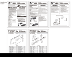
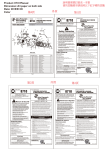
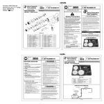
Product: PR14 Manual
Dimension: 8.5"x 11"/page
Date: 2008/06/24
Color:
Black
PR14
PR14
AIR RIVETER - 3/32", 1/8",
5/32", 3/16" AND 1/4" CAPACITY
www.astrotools.com
1 YEAR LIMITED WARRANTY
•Astro Pneumatic Tool Co. warrants our products to the original user against
defective material or workmanship for a period of 1 year (except where noted on our
price schedule) from the date of 1st use. Astro reserves the right to determine
whether the product failed because of defective material, workmanship or other
causes and to charge back for missing parts. Astro Pneumatic Tool Co., at its
discretion, will repair products covered under this warranty free of charge. The
distributor should direct the original user to return the product (with the exceptions
listed below) with the distributor’s name, address, adequate proof of date of
purchase or a copy of warranty card, and a short note explaining the problem.
Failures caused by accident, alteration, or misuse are not covered by this
warranty.
•Astro Pneumatic Tool Co. or its authorized service representatives must perform all
warranty repairs. Any repair to the product by unauthorized service representatives
voids this warranty. The rights under this warranty are limited to the original user and
may not be transferred to subsequent owners.
• Power tools cannot be used in potentially explosive
atmospheres unless especially designed for that purpose.
• Unexpected tool movement or breakage of inserted
tool may cause bodily injury.
• Power tools should be disconnected from their
energy source changing or servicing any parts.
• Never put any body part, clothing hair etc. between the
tool and the work area as serious bodily injury can result.
• Guard against the risk of being injured by
whipping air hoses.
• Guard against unexpected tool movement or
breakage of the rivet may cause injury.
• Unstable postures may not allow counteracting of
normal or unexpected movement of the air tool.
SPECIFICATIONS:
Rivet Capacity:
Overall Length:
Net Weight:
Stroke:
Motor:
Air Inlet Thread NPT:
Air Hose I.D. Size:
Avg. Air Consumption:
Air Pressure:
OPERATION
After unpacking the air powered rivet gun, make sure all of
the parts listed are supplied. In addition to parts supplied are
two wrenches you will need for replacement of various parts
on the PR14. Keep the packages containing wrenches, one
3/32 rivet nosepiece, one set of jaws and the bottle in a safe
place. Install the plastic rivet catcher (bottle) (#PR14-15)
and add the ¼ NPT air nipple to the air inlet side located
near the base. Add a few drops of air tool oil or #10 Spindle
oil to the air inlet near the base of the air riveter also add a
drop or two of oil to the Nose Piece Jaws (#PR14-4) through
the end of the Nose Piece (#PR14-1). Next squeeze the
operating handle Trigger (#PR14-25) several times before
inserting a rivet.
When you insert a rivet keep your hands clear of Trigger(#PR14-25).
Insert rivet shank till the button is seated against the Nose Piece
(#PR14-1), just prior to squeezing the trigger put a slight amount of push
pressure against the rivet and work piece. Most of the time when using
aluminum rivets one squeeze of the trigger will be sufficient to set the
rivet, however it may take more than one squeeze depending on the
length of the rivet and the type of rivet material (aluminum or steel). Make
sure that if the rivet has not set that you release the trigger and push the
nose piece against the rivet button again till the shank separates from
the rivet.
The oil and water extractor should not be mounted on or near the air
compressor.
The temperature of air is greatly increased during compression. As the air
cools down to room temperature, in the air line, on its way to the Air Power
Tool, the moisture contained in it condenses. Thus, for maximum
effectiveness, the oil and water extractor should be mounted at some point
in the air supply system where the temperature of the compressed air in the
line is likely to be lowest. Air lines must be properly drained daily. Each low
point in an air line acts as a water trap. Such points should be fitted with an
easily accessible drain. See diagram below. Pitch all air lines back towards
the compressor so that condensed moisture will flow back into the air
receiver where it can be drained off. Drain daily.
SUGGESTED AIR LINE CONNECTION
Pitch pipe back toward air receiver
It is easier to replace the nose pieces if you remove the Outer Cylinder
(#PR14-02) there by relieving spring pressure on the nose piece. Please
refer to FIG. 1. You must also remove the outer cylinder if you are going to
replace the set of jaws (3 required) (#PR14-04). Please refer to FIG. 4.
Unlike the older models, the PR14 uses one set of jaws for all rivet sizes.
Any time you remove the Outer Cylinder always add a little lubricant to the
Principal Axis (#PR14-09) that the Jaw Cylinder (#PR14-07) screws onto.
Please refer to FIG. 2. You will find that one set of jaws will probable last a
very long time.
Daily: Add a few drops of oil to the air inlet.
When necessary add a drop or two of #10 Spindle oil or good quality air
tool oil thru the Nose Piece (#PR14-01)) to lubricate the rivet shank jaws.
Always empty the plastic rivet catcher (bottle) (#PR14-15) after it fills to
no more than 25% of its capacity or the rivets might start stacking upon
one another.
Always keep your air riveter clean and oiled, use only filtered air from
your air compressor that does not contain debris and water as unfiltered
air can cause premature failure of your air tools.
Before performing any service or maintenance to the air
powered rivet gun and/or its componets, always disconnect the air supply and bleed off any air from the rivet
gun by squeezing the handle several times.
PLEASE DO NOT RETURN ANY PRODUCT WITHOUT CALLING
1-800-221-9705 FOR INSTRUCTIONS
PIPE SIZE, I.D. (Inches)
Unpacking
Compressor unit
Air Flow
CFM
When unpacking, check the parts diagram and part number listing
on page 5 to make sure all parts are included. If any parts are
missing or damage, please call your distributor.
AIR RIVETER - 3/32", 1/8", 5/32", 3/16" AND 1/4" CAPACITY
1/4"
10-7/8" (280mm)
3-1/2lbs. (1.6kg)
15mm
1/2hp
1/4"
3/8" (10mm)
2.320 Liter/Stroke
90-120psi
How to change jaw assembly if ever necessary?
SERVICING COMPONETS
Astro Pneumatic Tool Company
372 Old US Highway 52 South
Mt. Airy, NC 27030
• Includes the following nosepieces: 1/4" (6.4mm), 3/16" (4.8mm),
5/32" (4mm), 1/8" (3.2mm), 3/32" (2.4mm)
• Performs well at any angle
• Gets into hard-to-reach areas
• The ¼" Nose piece is located on the end of the outer cylinder (PR14-02).
The 3/16", 5/32", 1/8" are threaded into the bottom Air Cylinder lid
(PR14-24).The 3/32” will be found inside a plastic bag with
other related parts.
• Provides quick, quiet and comfortable operation preventing user fatigue
AIR RIVETER - 3/32", 1/8",
5/32", 3/16" AND 1/4" CAPACITY
GENERAL OPERATION
AIR SUPPLY
•This warranty is in lieu of all other warranties, expressed or implied, including
warranties of merchantability and fitness for a particular purpose. Some states do
not allow the exclusion of limitations of incidental or consequential damages so the
above limitations may not apply to you. All claims must be sent to:
PR14
AIR RIVETER - 3/32", 1/8",
5/32", 3/16" AND 1/4" CAPACITY
Drain
Daily
50
100
150
10
1/2"
3/4"
3/4"
20
3/4"
3/4"
3/4"
3/4"
30
3/4"
3/4"
1"
1"
40
1"
1"
1"
1"
50
1"
1"
1"
1"
70
1"
1"
How to change nose pieces?
Install drain at
each low point
Length of Pipe (feet)
200
Drain
Daily
Oil and Water
Extractor
1-1/4" 1-1/4"
Drain
Daily
25 FEET OR MORE
Oil and Water Extractor should be at least 25 ft. from the compressor. Further if possible.
1. Remove outer cylinder (#PR14-02) as in FIG. 1 with the
wrenches supplied.
2. Unscrew nose piece (#PR14-01) from outer cylinder, thread the
desired nose piece onto the outer cylinder just 2 or 3 threads.
Please refer to FIG. 3.
3. Next, add a few drops of light machine oil #10 spindle oil or a good
quality air tool oil to the jaws and also add a little white grease to
the smooth principal axis (#PR14-09) of the jaw cylinder
threaded shaft.
4. Finally, screw the outer cylinder back onto the rivet gun by hand
and tighten both the nose piece and the outer cylinder
with the wrenches supplied.
FIG. 1
1. Remove outer cylinder (#PR14-02) as in FIG. 1.
2. Next, using the two wrenches supplied to unscrew jaw carrier
(#PR14-03) from jaw cylinder (#PR14-07) as in Fig. 2. Unscrew by
hand the jaw cylinder holding the rivet gun on a flat surface this will
allow the jaw pusher (#PR14-05) and the jaw pusher spring
(#PR14-06) to remain together as an assembly. Please refer to FIG. 3.
Be careful when unscrewing the jaw carrier as there is a slight spring
pressure forcing the jaw carrier away from the handle.
FIG. 1
3. When the jaw carrier is unscrewed, tilt the nose part of the jaw carrier at a
slight downward angle to help prevent the jaws from falling out see FIG. 3.
4. Before reassembly throughly clean with a brush and lubricate all inner
assembly parts with #10 spindle oil or good quality air tool oil.
FIG. 3
5. Assembly of jaws set PR14-04. Hold the jaw carrier in the palm of your
hand as in FIG. 4 leaving about ¼” (6MM) space between the palm
and the jaw carrier.
6. Next, drop each jaw into the jaw carrier at 120 degrees angle till all three
jaws are evenly protruding through the jaw carrier. You may find a small
amount of light white grease will hold each jaw to one another as well as
holding the individual jaws in the jaw carrier.
7. While holding the rivet gun bottom down on a flat surface, reassemble
the jaw carrier to the jaw cylinder, and reverse the removal procedure
for reassembly.
NOTE: Be careful that all of the jaws are aligned properly and protruding evenly
through the jaw carrier before reassembling.
FIG. 4
8. After assembling and tightening the jaws in the jaw carrier check the
head length of the rivet gun head using the wrench provided as in FIG.5.
FIG. 2
FIG. 5
Adjust your air compressor air pressure to 90-120psi, (6.21-8.28 Bars).
NOTE:
If you use extra long air hoses more than 50 feet long you may have to increase the air pressure to compensate for reduced air operating pressure.
Always use clean, dry air that has been filtered and is free of dust, corrosives fumes or moisture. You should drain the air tank daily and
clean the filtering system as needed. To use more air pressure will shorten that air tools life and may lead to premature failure of this Air
Riveter Gun and could cause injury. Use the standard air supply information located in the above diagram.
Page 1
Page 2
PR14
AIR RIVETER - 3/32", 1/8",
5/32", 3/16" AND 1/4" CAPACITY
MAINTENANCE
Cleaning for the Head of Riveter
Adding oil for hydraulic riverter
1. Turn off air supply by disconnecting air hose from rivet gun.
Bleed any air remaining by squeezing the handle several
times.
2. Use the supplied wrench to dismantle the riveter head
as in FIG. 1.
3. Use wrench supplied to open the cover located on the bottom
of the rivet gun as in FIG. 2.
4. Remove piston from cylinder as FIG. 3 illustrates.
5. Clean the inside of the cylinder, clean the piston stem
and lubricate the o ring cover seal as in FIG. 4
6. Lubricate the intake with #10 spindle oil or a good quality
air tool oil, (fill only to the top of the center intake tube) as
shown in FIG. 5 add a light coat of white grease to the
inner cylinder wall.
7. Reassemble as in FIG. 6.
FIG. 1
FIG. 2
FIG. 3
FIG. 4
FIG. 5
FIG. 6
1. Turn off air supply. Assure all pressure is released prior
to disassembly.
2. Use spanner wrench to dismantle the riveter head as FIG. 1.
3. Use spanner wrench to disassemble as shown in FIG. 2.
4. Clean all inner/assembly parts of the riveter head with a brush.
5. Reassemble the inner/assembly parts.
6. Oil the parts and reassemble riveter head completely.
FIG. 1
372 Old US Highway 52 South
Mount Airy, NC 27030
PR14
Call 1.800.221.9705 for questions concerning performance of the product
or other inquiries.
Index
No.
1
2
3
4
5
6
7
8
9
10
11
12
13
14
15
16
17
18
19
20
21
22
23
24
25
26
27
28
29
30
31
32
33
B01
B02
B03
B04
B05
B06
B07
B08
B09
B10
B11
B12
B13
B15
B16
FIG. 2
AIR RIVETER - 3/32", 1/8", 5/32", 3/16" AND 1/4" CAPACITY
Lubrication
Every three to four hours of operation, lubricate the jaws
(#PR14-04) and the principal axis (#PR14-09) is necessary.
Use of a thicker oil can lead to adverse performance or
malfunction if a thicker oil is used by accident,
wash it away immediately.
Storage
Avoid storing air tools in a locations subject to high humidity. If the
tool is left after being used, the residual moisture inside the tool
can cause rust. Before storing and after operation, oil the tool at
the air inlet with #10 spindle oil or a good quality air tool oil and
run the tool for several cycles.
Disposal
Dispose the worn out tool according to national regulations.
Ordering Service Parts
For further operational and handling information or for replacement parts and components, contact the sales agent from whom
you purchased the tool or the service division of our company.
*In ordering parts and components, give each part number, name and quantity.
• Includes the following nosepieces: 1/4" (6.4mm),
3/16" (4.8mm), 5/32" (4mm),1/8" (3.2mm), 3/32" (2.4mm)
• Powerful durable, high speed production tool
• Quick release air valve permits cylinder to return quickly
for high speed assembly operations:
Prevents overloading for long life
• Performs well at any angle
• Gets into hard-to-reach areas
• Provides quick, quiet and comfortable operation
preventing user fatigue
Page 4
Page 3
AIR RIVETER - 3/32", 1/8",
5/32", 3/16" AND 1/4" CAPACITY
Page 4
PR14-01
PR14-02
PR14-03
PR14-04
PR14-05
PR14-06
PR14-07
PR14-08
PR14-09
PR14-10
PR14-11
PR14-12
PR14-13
PR14-14
PR14-15
PR14-16
PR14-17
PR14-18
PR14-19
PR14-20
PR14-21
PR14-22
PR14-23
PR14-24
PR14-25
PR14-26
PR14-27
PR14-28
PR14-29
PR14-30
PR14-31
PR14-32
PR14-33
PR14-B01
PR14-B02
PR14-B03
PR14-B04
PR14-B05
PR14-B06
PR14-B07
PR14-B08
PR14-B09
PR14-B10
PR14-B11
PR14-B12
PR14-B13
PR14-B15
PR14-B16
Nosepiece
Outer Cylinder
Jaw Carrier
Jaws
Jaw Pusher
Jaw Push Spring
Jaw Cylinder
Case Lock Nut
Principal Axis
Plastic Ring
Handle
Lead Axis
Plastic Ring
Restore Spring
Bottle
Airproof Lid
Silencer
Lock Nut
Air Cylinder
Pole Piston
Cushion
Piston
Nut
Air Cylinder Lid
Trigger
Linker
Press Plank
Air Valve
Valve Sprint
Copper Washer
Airproof Plastic
Airproof Spring
Airproof Nut
O-Ring
O-Ring
O-Ring
O-Ring
O-Ring
Spring Pin
Spring Pin
Spring Pin
Spring Pin
O-Ring
O-Ring
O-Ring
O-Ring
O-Ring
Pot Hook
5
1
1
1
1
1
1
1
1
1
1
1
1
1
1
1
1
1
1
1
1
1
1
1
1
1
1
1
1
1
1
1
1
1
1
1
1
1
1
1
1
1
1
1
1
1
1
1
FIG. 2