1
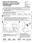
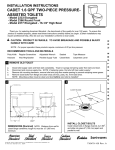
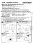
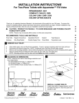
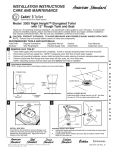
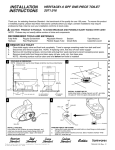
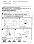
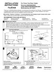
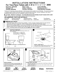
INSTALLATION INSTRUCTIONS
GLENWALL 1.6 GPF TWO-PIECE
PRESSURE-ASSISTED
WALL-MOUNTED TOILETS
Model 2093 Elongated
Meets the American Disabilities Act Guidelines and ANSI A117.1
Requirements for the Physically Challenged
Thank you for selecting American Standard - the benchmark of fine quality for over 100 years. To ensure this
product is installed properly, please read these instructions carefully before you begin. (Certain installations may
require professional help.) Also be sure your installation conforms to local codes.
U S E
CAUTION: PRODUCT IS FRAGILE. TWO PEOPLE ARE RECOMMENDED FOR
HANDLING TO AVOID BREAKAGE AND POSSIBLE INJURY!
NOTE: For proper operation product requires a minimum of 25 psi working line pressure
FINISHED WALL
29-1/2
(749mm)
Closet Carrier Support
Putty Knife
Regular Screwdriver
Adjustable Wrench
Sealant
Tape Measure
Flexible Supply Tube
Carpenters Level
Refer to instructions supplied with
wall carrier for proper installation
of 4-bolt support system wall
cavity requirements and rough-in
information for waste outlet piping.
C/L
14-3/4
(375mm)
30
(762mm)
OR
32
(813mm)
6
(152mm)
3-1/4
(83mm)
5-1/4
(133mm)
3-7/8
(98mm)
5/8
(16mm)
When installed, top of seat is
17" to 19" (432mm to 483mm)
from the finished floor.
19-1/2
(495mm)
1-1/2
(38mm)
8-1/2
14-1/2 (216mm)
(368mm)
OR
16-1/2
(419mm)
7-1/2
(191mm)
9
(229mm)
191mm
(7-1/2)
*
FIN.
FLOOR
4-1/8
(105mm)
OR
6-1/8
(156mm)
3-1/4
(83mm)
3/4 (19mm)
REF.
SUPPLY AS
REQUIRED
(4) 7/8
(22mm) DIA. HOLES
C/L OF WASTE
OUTLET
2
FINISHED WALL
FIXTURE MOUNTING
2-1/8"
Fixture studs should project
2-1/8" from face of finished wall.
(4) STUDS
Side View
Front View
Saniwares
Product names listed herein are trademarks of American Standard Inc.
© American Standard Inc. 2006
730480-100 Rev B
F U T U R E
RECOMMENDED TOOLS
AND MATERIALS
F O R
1
S A V E
!
3
Place back-up nuts on both bottom bolts, and
the top left-hand bolt only.
4
Adjust the two lower back-up nuts so that front
face of nuts is flush with finished wall.
Using a level, adjust the top left back-up nut so that
it is in the same vertical plane as the lower left back-up
nut. (If wall surface is irregular, the three back-up
nuts must be positioned to allow a minimum 1/16"
gap between fixture and wall surface.)
Adjust waste horn to project 5/16" from
finished wall.
FINISHED WALL
FINISHED WALL
CLOSET
CARRIER
SYSTEM
1/16" (IRREGULAR
WALL SURFACE)
(3) NUTS
LEVEL
WASTE
HORN
5/16
6
5
NOTE: Bearing nuts and washers must be set
to take full loading from the fixture allowing
1/16" clearance between fixture and wall.
TANK MTG.
BOLTS
Follow support manufacturer's recommended
setting of closet outlet connection.
Place felt or neoprene gasket (wax ring not
recommended) on closet outlet.
SANITARY
BAR
When the fixture is installed, closet outlet
gasket must be compressed sufficiently to
assure a gas and watertight seal.
The following steps require a helper:
SPONGE
WASHER
WASHER
NUT
INSTALL TANK AND TOILET SEAT
Install bowl on support using cap nuts and fiber
washers with the back-up nuts and washers.
Install large rubber gasket over threaded outlet on
bottom of tank with tapered side out and lower tank onto
bowl so that the tapered end of gasket fits evenly into
bowl water inlet opening, and tank mounting bolts go
through mounting holes. Secure with metal washers
and nuts.
DO NOT APPLY TOP RIGHT FIBER WASHER
AND CAP NUT UNTIL OTHER CAP NUTS
HAVE BEEN FIRMLY TIGHTENED USING A
WRENCH.
With tank parallel to wall, alternately tighten nuts until
tank is snugged down evenly against sanitary bar on
bowl.
Install top right cap nut with fiber washer and
run up hand tight. Wrench tighten approximately
1/4 turn.
!
Apply sealant to gap between bowl and finished
wall. Remove excess sealant.
CAUTION: DO NOT OVERTIGHTEN
NUTS MORE THAN REQUIRED
FOR A SNUG FIT!
Install toilet seat according to manufacturer's directions.
730480-100 Rev B
- 2 -
7
8
TANK
SET
SCREW
WATER INLET
1/32"
APPROX.
WASHER
FLEXIBLE
SUPPLY
COUPLING NUT
VALVE NUT
COMPRESSION
COLLAR
ADJUSTMENTS
The flushometer tank is designed and factory-adjusted to provide a consistent,
safe seal depth in the bowl after each flush. Field refill adjustment is not required.
The refill has been preset and locked.
TRIM PLATE
VALVE
CONNECT WATER SUPPLY
Connect water supply line between
shutoff valve and tank water inlet
fitting. Tighten coupling nuts
securely.
Turn on supply valve and allow
flushometer tank to fill.
Check for leakage at fittings,
tighten or correct as needed.
FLUSH ACTUATOR ADJUSTMENT - The spacing between the bellcrank and
flush actuator may be adjusted to assure positive operation of the trip lever.
Proceed as follows:
Remove tank cover and check that there is approximately 1/32" (0.8mm) gap
between the top of the actuator and bottom of the spring rod when it is lifted to
remove slack from linkage.
If necessary, loosen set screw in actuator cap and turn cap to increase gap
(clockwise) or decrease gap (counterclockwise), as needed.
Tighten setscrew securely after adjustment is completed. Replace tank cover.
REPAIR PARTS LIST
NOTE: "XXX" and "YYY" represent color or trim finish options.
Specify when ordering.
3
2
1
4
ITEM
PART NO.
1
738473-YYY0A
738494-YYY0A
4098.100.XXX
2
5
8
9
3
4
5
7
6
10
6
7
8
9
10
DESCRIPTION
TRIP LEVER-LH
TRIP LEVER-RH
TANK (COMPLETE WITH COUPLING
COMPONENTS AND L.H. TANK TRIM)
4098.800.XXX
TANK (COMPLETE WITH COUPLING
COMPONENTS AND R.H. TANK TRIM)
735083-400.XXX TANK COVER
3402.016.XXX
BOWL
738493-0070A
SPRING ROD ASSEMBLY-LH
738495-0070A
SPRING ROD ASSEMBLY-RH
730599-0070A
COUPLING GASKET
738496-0070A
LOWER SUPPLY ASSEMBLY (35 PSI)
047562-0070A
UPPER SUPPLY ASSEMBLY
047563-0070A
VALVE CARTRIDGE ASSEMBLY
730292-0070A
TANK COUPLING KIT
QTY
1
1
1
1
1
1
1
1
1
1
735083-600.XXX TANK COVER FOR LOCKING DEVICE 1
603111-0030A
COVER LOCKING DEVICE KIT
1
CARE AND CLEANING
When cleaning your toilet, wash it with mild, soapy water, rinse thoroughly with clear water and dry with a soft cloth.
Avoid detergents, disinfectants, or cleaning products in aerosol cans. NEVER use abrasive scouring powders or
abrasive pads on your toilet seat. Some bathroom chemicals and cosmetics may damage the seat's finish.
730480-100 Rev B
- 3 -
TROUBLESHOOTING GUIDE
NOTE: The presence of a small amount of water in the bottom of the tank is normal. The air inducer is designed to leak
for short periods during each flush cycle as a self-cleaning action. Drippage is drained into the bowl. If used on water
system containing excessive sand and/or debris, a periodic cleanup of inlet strainer is recommended. (See enclosed
instructions for strainer cleaning.)
!
WARNING
When servicing or replacing components of the flushometer tank system, be sure that the
water supply is shut off and the toilet is flushed to relieve pressure in the flushometer tank.
For service of the Flushometer Tank System, see enclosed literature.
PROBLEM
Does not flush
Poor or sluggish
flush
POSSIBLE CAUSE
a.
b.
c.
Water supply valve closed.
Flush actuator incorrectly set.
Supply line blocked.
d.
Trip lever linkage damaged.
a.
Supply valve partly closed.
b.
c.
d.
Plugged inlet strainer.
Supply pressure too low.
Partially clogged trapway and/or
drain pipe and/or vent.
Malfunctioning pressure regulator.
e.
Toilet leaks
Toilet does not
shut off
CORRECTIVE ACTION
a.
b.
a. Open valve and allow water to fill tank.
b. Follow instruction to adjust flush actuator.
c. Shut off water supply, disconnect supply line, and inspect
all gaskets and washers. Reassemble.
d. Check trip lever, linkage, and spring rod assemblies
for damage.
a. Open supply valve fully. Be sure that proper supply tube
size is used.
b. Remove and clean strainer per enclosed instructions
c. Normal supply pressure must be at least 25 psi.
d. Remove obstruction. Consult a plumber if necessary.
e. Replace lower supply assembly.
a. Review Step 7 of installation procedure.
b. Review Step 3 through 5 of installation procedure.
c.
Poor supply line connection.
Poor bowl to wall waste outlet
connection.
Tank/bowl connection.
a.
b.
Supply pressure too low.
Flush actuator incorrectly set.
a. Normal supply pressure must be at least 25 psi.
b. Follow instructions to adjust flush actuator.
c. Check tank for movement. Refer to Step 6.
AMERICAN-STANDARD ONE-YEAR LIMITED WARRANTY
If inspection of this American-Standard plumbing product, within one year after its initial installation, confirms that it is defective in materials or
workmanship, American-Standard will repair or, at its option, exchange the product for a similar model.
This warranty does not apply to local building code compliance. Since local building codes vary considerably, the purchaser of this product should check
with a local building or plumbing contractor to insure local code compliance before installation.
This warranty shall be void if the product has been moved from its initial place of installation; if it has been subjected to faulty maintenance, abuse,
misuse, accident or other damage; if it was not installed in accordance with American-Standard's instructions; or if it has been modified in a manner
inconsistent with the product as shipped by American-Standard.
American-Standard's option to repair or exchange the product under this warranty does not cover any labor or other costs of removal or installation, nor
shall American-Standard be responsible for any other incidental or consequential damages attributable to a product defect or to the repair or
exchange of a defective product, all of which are expressly excluded from this warranty. (Some states or provinces do not allow the exclusion or
limitation of implied warranties, so this exclusion may not apply to you.)
This warranty gives you specific legal rights. You may have other statutory rights that vary from state to state or from province to province, in which case
this warranty does not affect such statutory rights.
For service under this warranty, it is suggested that a claim be made through the contractor or dealer from or through whom the product was purchased, or
that a service request (including a description of the product model and of the defect) be sent to the following address:
In the United States:
American Standard Inc.,
P.O. Box 6820
Piscataway, New Jersey 08855
Attention: Director of Consumer Affairs
In Canada:
American-Standard,
2480 Stanfield Road
Mississauga, Ontario
Canada L4Y 1S2
For residents of the United States,
warranty information may also be
obtained by calling the following
toll free number: (800) 442-1902
www.americanstandard-us.com
Toll Free: (800) 387-0369
www.americanstandard.ca
730480-100 Rev B
- 4 -
In Mexico:
Customer Service Manager
Ideal Standard, S.A. de C.V.
Via Morelos #330
Col. Santa Clara
Ecatepec 55540 Edo. Mexico
www.americanstandard.com.mx