1
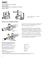
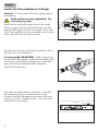
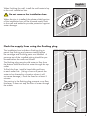
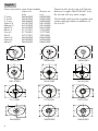
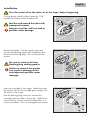
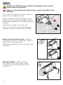
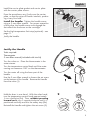
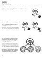
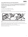
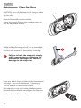
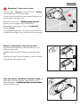
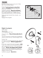
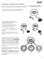
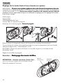
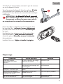
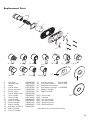
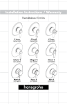
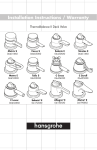
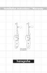
Installation Instructions / Warranty
ThermoBalance II Rough & Trim
C Lever
06064XX0
C Scroll
06065XX0
C Cross
06066XX0
Solaris² E
04147XX0
Allegro² E
04153XX0
Metro² E
04159XX0
Metris S
31317XX1
Focus S
31736XX1
Talis S
32317XX1
English
ThermoBalance II Rough
06623000
ThermoBalance II Rough with Stops
06627000
The cartridge shown is included
with the trim kit.
The Service (Isolation) Stops
(For the sake of clarity, the plastic installation box
(i-box) is not shown in these illustrations. The
i-box should not be removed.)
screwdriver
slots
Rough-in 06627000 has service (isolation)
stops built onto the valve. When the screwdriver slots is horizontal, the stops are in the
“on” position. When the screwdriver slots are
vertical, the stops are in the “off” position.
When connecting the hot and cold supplies,
hold the stop steady with a wrench to avoid
stop mis-alignment, and breakage of the factory sealed thread compound.
Technical Specifications
Recommended pressure
Maximum hot water temperature
Recommended hot water temp.
Nominal capacity @ 45 psi
Nominal capacity @ 60 psi Safety stop
Maximum output temperature
½” NPT connections
45 - 72 psi
165° F*
120° - 140° F*
8 gpm
11.5 gpm
100° F
110° F**
*Please know and follow all applicable local plumbing codes when setting the temperature on the water heater.
**The high temperature limit stop may be reset to comply with local plumbing codes. See page 11.
English
Installation Considerations
• For best results, this unit should be installed by a licensed, professional plumber.
• Large pressure differences between the hot and cold supplies should be balanced.
• Before beginning the installation, please read the instructions thoroughly. Inspect the
product and make sure that all parts are present and in good condition. If you have
questions, contact Hansgrohe Technical Services.
• ThermoBalance II rough 06623000 does not include service stops. If service stops are
required by local plumbing code, order the stops separately (part #06900300) or order
ThermoBalance II rough 06627000, which incorporates service stops.
• The ThermoBalance II is intended for use in a two-function shower. DO NOT plug any
outlet.
• The ThermoBalance II rough must be used with a ThermoBalance II trim kit. Do not attempt to use with any other trim kit.
• Do not attempt to use this valve in combination with a diverter tub spout.
Installation Suggestions
ok!
ok!
no!
Do not use a diverter tub spout!
Use for a two-feature installation only! Do not plug either outlet!
English
Install the ThermoBalance II Rough
Caution: Turn the water off at the supply before
proceeding.
Both outlets must be plumbed. Do
not plug any port.
Install the hot and cold supply lines to the rough.
The hot supply must be connected to the hot inlet
and the cold supply must be connected to the cold
inlet. If the supplies are not connected to the correct
inlets, the valve cannot work correctly.
(for the sake of clarity, the plastic installation box is
not shown in this illustration.)
If using model 06627000: When connecting
the hot and cold supplies, hold the stop steady with
a wrench to avoid stop mis-alignment, and breakage of the factory sealed thread compound.
Install both outlet lines.
The valve should be level in all planes. It should
be installed so that the outside surface of the
finished wall falls between the minimum and maximum lines on the installation box. This will insure
that the trim fits properly.
English
When finishing the wall, install the wall material up
to the oval installation box.
Do not remove the installation box.
When the trim is installed, the plaster shield portion
of the installation box will be trimmed nearly flush
to the wall and sealed to provide protection against
water damage.
Flush the supply lines using the flushing plug
The installation box includes a flushing plug to
permit line flushing and pressure testing before
the cartridge and finishing parts are installed. A
pressure test of the installed piping should be performed before the walls are closed.
The flushing plug permits cold water to flow from
the bottom outlet and the hot water through the top
outlet.
To flush the lines, install a hose bibb and hose
to each outlet line. (Using a hose will permit the
water to be directed to a location where it will
not cause damage.) Flush the lines for at least 5
minutes.
The porting in the flushing plug prevents cross flow.
However, it does not stop the flow of water through
the outlets.
English
These instructions
C Lever
C Scroll
C Cross
Solaris² E
Allegro² E
Metro² E
Metris S
Focus S
Talis S
Solaris E
Stratos E
Metro E
cover these models:
Valve trim
Shower set
only
trim
06064XX0
06082XX0
06065XX0
06083XX0
06066XX0
06084XX0
04147XX0
04150XX0
04153XX0
04156XX0
04159XX0
04162XX0
31317XX1
31324XX1
31736XX1
31772XX1
32317XX1
32324XX1
06636XX0
06642XX0
06580XX0
06586XX0
06656XX0
06662XX0
These trim kits are for use with ThermoBalance II roughs 06623/06627 only.
Do not use with any other rough.
The finished wall must be complete and
made watertight before installation of
this trim kit.
06064XX0
06066XX0
06065XX0
04147XX0
04153XX0
04159XX0
31317XX1
31736XX1
32317XX1
06636XX0
06580XX0
06656XX0
English
Installation
Turn the water off at the main, or at the stops, before beginning.
Cut the plaster shield so that it extends 1/16”
outside the surface of the finished wall.
Seal the wall around the i-box with
waterproof sealant.
Failure to seal the wall can lead to
possible water damage.
Remove the label. Cut the support arms that
connect the flushing plug to the installation box.
Remove the flushing plug. Do not discard the
screws.
Be sure to remove the blue
flushing plug sealing gasket.
Failure to remove the gasket
can result in damage to the
cartridge and possible water
damage.
Insert the cartridge in the rough. Make sure that
the locator tab on the cartridge goes straight into
the notch in the rough.
Use the flushing plug screws to connect the
cartridge retainer plate to the rough. Tighten the
screws evenly, using a manual screwdriver, in a
cross-wise pattern. Do not overtighten the screws.
notch
locator
tab
English
Perform the following test to check for damage to the ceramic
plates inside the stop unit.
Failure to correctly perform this test can result in possible water
damage.
Turn on the water supplies. Grasp the stop unit
portion of the cartridge and turn it.
stop unit
If there is a leak around the cartridge, turn the
supplies off, and remove the cartridge. Confirm
that the sealing gasket from the flushing plug was
removed.
Reinstall the cartridge. Turn the stop unit.
If the unit continues to leak, contact Hansgrohe
Customer Service for a replacement cartridge.
Solaris oval escutcheon only: Install the
white spacers on the carrier plate (a). Install two
Duotec strips on the spacers (b).
Install the remaining two strips on the back of the
escutcheon.
a
b
All other models: Install two Duotec
strips directly on the carrier plate. Install
the remaining two strips on the back of the
escutcheon.
English
Install the carrier plate gasket and carrier plate
with the carrier plate screws.
Press the escutcheon very firmly over the carrier
plate, so that the strips of Duotec interlock, producing a very firm hold.
Install the handle: Tighten the handle screw,
using a 3 mm Allen wrench. For proper operation
of the valve, the handle screw must engage the
slot milled into the brass on the cartridge.
Set the high temperature limit stop (optional) -- see
page 11.
Justify the handle.
Justify the Handle
Tools required:
Thermometer
3 mm Allen wrench (included with trim kit)
Turn the valve on. Place the thermometer in the
water stream.
Turn the temperature control knob until the water
coming out measures 100° on the thermometer.
Turn the water off using the lever part of the
handle.
Use the 3 mm Allen wrench to loosen the set screw
on the bottom of the handle. Remove the handle
from the valve (1).
Hold the lever in one hand. With the other hand,
turn the temperature control knob approximately
½ turn clockwise (2a). Then, without pressing
inward on it, turn it counter-clockwise until it is
positioned vertically and hits the safety stop (2b).
2
Reinstall the handle and tighten the set screw (3).
a
b
English
User Instructions
The ThermoBalance II has two control features: the Temperature Selector and the Diverter /
Volume Control.
The Diverter/Volume Control handle controls the water flow.
The center position is “off”.
Turn the handle counter-clockwise to send
the water to outlet I (the bottom outlet).
Turn it clockwise to send the water to
outlet II (the top outlet).
The further you turn the handle from the
“off” position, the greater the water flow.
Turn the Temperature Selector counter
clockwise to make the water warmer.
It will stop when the water is 100° F
– this is the safety stop.
Override the safety stop by pressing inward on the Temperature Selector and
continuing to turn it counter-clockwise.
Turn the Temperature Selector clockwise
to make the water cooler.
IMPORTANT: the Temperature Selector
will not automatically “reset” to below
100° when the water is turned off.
100°
10
<100°
>100°
English
Set the High Temperature Limit Stop (optional)
IMPORTANT: Many municipalities have codes limiting the maximum discharge temperature
of a shower valve to 110° F -- 112°F or less. In Massachusetts, the maximum output
temperature can be no higher than 112°F. Please know and follow all applicable local
codes when setting the high temperature limit stop.
Tools Required:
Thermometer
3 mm Allen wrench (included with trim kit)
Turn the hot and cold supplies to the valve on.
Turn the water on using the handle.
Use the 3 mm Allen wrench to loosen the set screw on the bottom of the handle. Remove
the handle.
Remove the clip and stop ring from the thermostatic cartridge stem. Put them in a safe
place.
Turn the thermostatic mixer stem with your fingers, clockwise to make the water cooler,
counter-clockwise to make the water warmer. Turn the stem until the water coming out is the
desired maximum high temperature – 110° in most areas.
Reinstall the stop ring so that it is against the stop. Reinstall the clip.
Justify and reinstall the handle.
11
English
Maintenance: Clean the filters
CAUTION: Turn off the water to the shower, either
at the main or with the service stops, before opening the valve.
Remove the handle and escutcheon.
Grasp the wrench flats on the cartridge stop unit
with an adjustable wrench.
While holding the stop unit still, use a second adjustable wrench or a 17mm deep socket wrench to
unscrew and remove the thermostatic cartridge.
Failure to hold the stop unit steady
while unscrewing or replacing the
thermostat cartridge will result in
damage to the stop unit.
Rinse any debris from the filters on the thermostatic
cartridge. Use a soft toothbrush, if necessary.
Do not attempt to remove the screens.
Lubricate the o-rings with white plumbers grease.
Reinstall the thermostatic cartridge in the stop unit.
Justify and reinstall the handle.
12
wrench flat
stop unit
Français
Corps d'encastrement ThermoBalance II 06623000
Corps d'encastrement ThermoBalance II avec butées d’arrêt
06627000
La cartouche illustré ici
est compris avec le jeu de
garniture.
fentes
ATTENTION : �������������������������������
La robinetterie brute 06627000
est munie de butées d’arrêt (arrêt d’isolation)
intégrées à la valve.����������������������������
Lorsque les fentes sont à
��������������������������
l’horizontale, les butées d’arrêt sont à la position
« on ».����������������������������������������������
Lorsque les fentes sont à la verticale, les
��������������������������������������������
butées d’arrêt sont à la position « off ».�����������
Utilisez
���������
une clé hexagonale de 3 mm pour ouvrir et
fermer les butées d’arrêt.
Lors du raccordement des arrivées d’eau
chaude et froide, tenez la butée d’arrêt
à l’aide d’une clé pour qu’elle ne bouge
pas afin de prévenir tout désalignement ou
rupture des éléments filetés scellés en usine.
Données techniques
Pression d’eau recommandée�����������
����������
45 -72 psi
Température maximum pour l’eau chaude�������
������
165°F*
Température recommandée pour l’eau chaude���������������
��������������
120°F – 140°F*
Capacité nominale à 45 psi������
�����
8 gpm
Arrêt de sûreté������
�����
100°F
Température de sortie maximale���������
�������
110°F**
Raccords NPT ½ po
Accrédité par UL
* Vous devez connaître et respecter tous les codes de plomberie locaux applicables pour le réglage de la température
du chauffe-eau.��
** Le degré de température de la butée de limite d’eau chaude peut être réglé de façon à satisfaire aux codes de
plomberie locaux.����������������������������������������������������������
Reportez-vous
��������������������������������������������������������
aux installations des jeux de garniture.��
13
Français
À prendre en considération pour l’installation :
• Pour de meilleurs résultats, cette valve devrait être installée par un plombier professionnel
certifié.
• Les différences importantes de pression d’arrivée d’eau chaude et d’eau froide doivent
être équilibrées pour que la valve fonctionne correctement.
• Veuillez lire attentivement les instructions avant de commencer l’installation.��������������
Examinez le
������������
produit et assurez-vous qu’aucune pièce ne manque et qu’elles sont toutes en bon état.
• Si vous avez des questions concernant cette installation, n’hésitez pas à contacter les
Services techniques de Hansgrohe au 800-334-0455
• La robinetterie brute 06623000 ne comprend pas les butées d’arrêt.����������������
Si le code de
��������������
plomberie locale exige l’utilisation de butées d’arrêt, commandez-les séparément (article
06900003) ou utilisez la robinetterie brute 06627000.
• Cette robinetterie brute ThermoBalance II est conçue pour les douches à deux fonctions
seulement.���������������������������������������������
Les deux sorties doivent être raccordées.�� Ne mettez de bouchon sur
�������������������������������������������
aucune des sorties.
• La pièce intérieure ThermoBalance II requiert l’utilisation du jeu de garniture
ThermoBalance II .������������������������������������������
N’utilisez
����������������������������������������
aucun autre jeu de garniture.
• N’essayez pas de combiner cette valve à un bec de baignoire inverseur.��
ok!
14
ok!
no!
Français
Installation :
Attention : �����������������������������������
Avant de commencer, fermez l’eau à
la valve principale.
Raccordez les conduites d’alimentation de l’eau
chaude et de l’eau froide à la pièce intérieure.��
La conduite d’alimentation de l’eau chaude doit
être installée dans l’orifice d’arrivée prévu pour
l’eau chaude, et la conduite d’eau froide doit
être installée dans l’orifice d’arrivée prévu pour
l’eau froide.�������������������������������������
S’il s’agit d’une construction non
�����������������������������������
récente, assurez-vous que les conduites d’alimentation d’eau froide et d’eau chaude n’ont pas été
inversées.������������������������������������������
Si les conduites ne sont pas raccordées
����������������������������������������
dans les bons orifices, la valve ne pourra fonctionner correctement.��
Modèle 06627000 seulement :��������������
Lors du rac������������
cordement des arrivées d’eau chaude et froide, tenez la butée d’arrêt à l’aide d’une clé pour qu’elle
ne bouge pas afin de prévenir tout désalignement
ou rupture des éléments filetés scellés en usine.
Installez les deux conduites de sortie.��
Ne mettez de bouchon sur aucune des
sorties.
Le robinet doit être de niveau sur tous les plans.
Installez la pièce intérieure de façon à ce que
la surface extérieure du mur fini tombe entre les
lignes « minimum » et « maximum » de la boîte
d’installation (« i-box »).��������������������������
������������������������
Vous vous assurez ainsi
que la garniture s’ajustera correctement.
15
Français
Le i-box doit demeurer sur la valve.�
Installez le matériau du mur jusqu’à le i-box.������
Une
����
fois la garniture installée, le i-box doit être coupée
presque à égalité du mur fini et scellée pour assurer une protection contre les dommages d’eau.
Rincez les conduites d’alimentation à l’aide du bouchon de rinçage.
Le i-box comprend un bouchon de rinçage permettant de rincer la conduite et de tester la pression
avant que la cartouche et la garniture ne soient
installées.
Il est recommandé d’effectuer un test de pression
de la tuyauterie avant de fermer les murs.
Le bouchon de rinçage permet à l’eau froide de
circuler dans la conduite de sortie du bas et à
l’eau chaude de circuler dans la conduite de sortie
du haut.
Fixez des embouts de raccordement pour tuyau
souple et des tuyaux aux orifices de sortie. Rincez
les conduites durant au moins 5 minutes. Servezvous des tuyaux pour diriger l’eau dans un
emplacement où le déversement ne causera aucun
dommage.
Le bouchon de rinçage prévient le débit croisé. Il
n’empêchera pas, toutefois, l’eau de circuler dans
les conduites de sortie. Si la construction doit être
mise sous pression, fermez les butées d’arrêt ou
obturez les conduites de sortie.
16
Français
Les instructions ci-après s’appliquent aux modèles suivants :
Ensemble mitigeur
Ensemble de
pour la douche
douche
C Lever
06064XX0
06082XX0
C Scroll
06065XX0
06083XX0
C Cross
06066XX0
06084XX0
Solaris² E
04147XX0
04150XX0
Allegro² E
04153XX0
04156XX0
Metro² E
04159XX0
04162XX0
Metris S
31317XX1
31324XX1
Focus S
31736XX1
31772XX1
Talis S
32317XX1
32324XX1
Solaris E
06636XX0
06642XX0
Stratos E
06580XX0
06586XX0
Metro E
06656XX0
06662XX0
Ces jeux de garniture
sont conçus pour les
corps d'encastrement
ThermoBalance II 06623000,
06627000.
Le mur doit être complètement
fini et étanche avant
l’installation de cet ensemble
de garniture.
06064XX0
06066XX0
06065XX0
04147XX0
04153XX0
04159XX0
31317XX1
31736XX1
32317XX1
06636XX0
06580XX0
06656XX0
17
Français
Installation
Avant de commencer, fermez l’eau à la vanne principale ou aux butées d’arrêt.
Coupez la boîte d’installation (i-box) de façon à
ce qu’elle dépasse de la surface du mur fini de
1/16 po.
Scellez le mur autour de la boîte
d’installation à l’aide d’un agent
d’étanchéité.
Retirez l’étiquette.
Coupez les huit branches de support reliant le
bouchon de rinçage à la i-box.�����������������
Enlevez
���������������
le bouchon de rinçage.�����������������������
Ne
���������������������
jetez pas les vis.
Assurez-vous d’avoir également
enlevé le joint bleu du bouchon de
rinçage.
Insérez la cartouche dans la pièce intérieure.�����
La
���
languette s’insère directement dans la coche de la
pièce intérieure.
Utilisez les vis du bouchon de rinçage pour fixer
la plaque d’arrêt de la cartouche à la pièce intérieure.��������������������������������������������
Serrez
������������������������������������������
les vis uniformément à l’aide d’un
tournevis manuel.�����������������������������
Ne serrez pas trop les vis.
���������������������������
18
coche
languette
Français
Attention! Exécuter ce test:
Ouvrez l’eau.����������
Tourner le dispositif d’arrêt. ���������
Vérifiez
l’étanchéité de tous les raccords.
dispositif
d’arrêt
Si une fuite se produit entre la pièce intérieure et
la cartouche, fermez l’eau.��
Retirez la cartouche.���������������������������
Vérifiez que le joint du
�������������������������
bouchon de rinçage a bien été enlevé.��
Réinstallez la cartouche. Tourner le
��������������
dispositif
d’arrêt encore.
�������
Si le problème persiste, contactez le Service à la
clientèle pour obtenir une cartouche de rechange.
Solaris uniquement (écusson ovale)
Enclenchez les espaceurs Duotec blancs sur la
plaque-support (a).
Installez deux bandes Duotec sur les espaceurs
(b).��
Installez les deux autres bandes au dos de l’écusson (plaque de la garniture).��
a
b
Tous les autres modèles (écusson rond) Installez deux bandes Duotec directement sur la
plaque-support.�����������������������������������
Installez
���������������������������������
les deux autres bandes
au dos de l’écusson.
19
Français
Installez la plaque-support et le joint à l’aide
des vis de la plaque-support.
Pressez fermement l’écusson sur la plaquesupport.�����������������������������������
Les
���������������������������������
bandes Duotec se fixeront en
place bien solidement.
Installez la poignée.��������������������������
Serrez
������������������������
la vis de la poignée à l’aide d’une clé hexagonale de 3 mm.��
La vis de la poignée doit s’engager dans la
fente taillée dans le laiton, sous la cartouche.
Réglez la butée limite de l’eau chaude – voir
page 22.
Réglage de la poignée.
Réglez la poignée
Outils requis :
Thermomètre
Clé hexagonale de 3 mm
Ouvrez la valve.��������������������������������
Placez le thermomètre dans le
������������������������������
jet d’eau.
Tournez le bouton de contrôle de la température
jusqu’à ce que l’eau qui s’écoule atteigne 100°F.
Fermez l’eau.
À l’aide d’une clé hexagonale de 3mm, desserrez
la vis de la poignée.���������������������������
Retirez
�������������������������
la poignée de la
valve.
D’une main, tenez le levier de la poignée,��������
et
������
de
l’autre main, faites tourner le bouton de contrôle
de la température d’environ ½ tour dans le sens
horaire. ������������������������������������������
Ensuite,
����������������������������������������
sans appuyer dessus, faites-le
revenir en le tournant dans le sens antihoraire,
jusqu’à ce qu’il soit en position verticale et qu’il
atteigne l’arrêt de sûreté.
2
Installez la poignée.����������������
Serrez
��������������
la vis.
a
20
b
Français
Instructions à l’intention de l’utilisateur
Le ThermoBalance II est pourvu de deux fonctions de contrôle :������������������������������
����������������������������
le bouton de contrôle de la
température et le levier de contrôle du débit / inverseur.
Le levier débit / inverseur contrôle le débit de l’eau.��
La position centrale est celle de l’arrêt (« off »).��
Tournez la poignée dans le sens
antihoraire pour envoyer l’eau à la
conduite de sortie du bas.��
Tournez la poignée dans le sens
horaire pour envoyer l’eau dans la
conduite de sortie du haut.�
Plus la poignée est éloignée de la
position « off », plus le débit d’eau
augmente.��
Il est impossible de faire fonctionner
les deux conduites de sortie en même
temps.�
Pour que l’eau soit plus chaude, tournez
le bouton de contrôle de la température
dans le sens antihoraire.�����������������
Le contrôle de
���������������
température s’arrête lorsque l’eau atteint
100°F – c’est l’arrêt de sûreté. �������
Pour
�����
outrepasser l’arrêt de sûreté, appuyez sur
le bouton de contrôle de la température
et continuez à le tourner dans le sens
antihoraire.
Pour que l’eau soit plus froide, tournez
le bouton de contrôle de la température
dans le sens horaire.
Important : le
������������������������
réglage du bouton de
contrôle de la température ne revient pas
automatiquement sous 100°F une fois
l’eau fermée.
100°
<100°
>100°
21
Français
Réglage de la butée limite d’eau chaude (en option)
IMPORTANT :���������������������������������������������������������������������������������
Plusieurs
�������������������������������������������������������������������������������
municipalités appliquent des codes limitant la température de sortie
maximale d’un robinet de douche à 110°F ou moins.� Dans le Massachusetts, la température
ne doit pas excéder 112°F. �����������������������������������������������������������������
Assurez-vous de bien connaître et de respecter tous les codes de
plomberie locaux applicables lorsque vous effectuez le réglage pour le réglage de la butée
limite d’eau chaude.
Outils requis :
Thermomètre
Clé hexagonale de 3 mm
Ouvrez l’eau à l’aide de la poignée.
Desserrez la vis de la poignée.���������������������
Retirez
�������������������
la poignée.
Retirez l’étrier et la bague de retenue de la tige de la cartouche thermostatique.��
Tournez la tige du mitigeur thermostatique jusqu’à ce que la température de l’eau chaude
atteigne le degré voulu – habituellement 110°F.
Réinstallez la bague de retenue de façon à ce qu’elle s’appuie sur la butée d’arrêt.��
Réinstallez l’étrier.
Réglez et réinstallez la poignée.
Entretien :��������������������������������
Nettoyage
������������������������������
des tamis de filtre
ATTENTION :� Avant
����������������������������������
de commencer, fermez l’eau,
soit à la vanne principale soit aux butées d’arrêt.
Retirez la poignée et l’écusson.
22
pan de
manoeuvre
dispositif
d’arrêt
Français
À l’aide d’une clé à molette, saisissez le pan de manoeuvre sur le dispositif d’arrêt.
Tenez fermement le dispositif d’arrêt en place.�����������
À
���������
l’aide
d’une seconde clé à molette ou d’une clé à douille
longue de 17 mm, dévissez la cartouche thermostatique
et retirez-la.
ATTENTION :��������������������������������
Le
�������������������������������
dispositif d’arrêt pourrait
être endommagé si vous ne le retenez pas
fermement en place lorsque vous retirez
ou remplacez la cartouche thermostatique.
Rincez les débris ou dépôts pouvant se trouver dans
les tamis de filtre.�����������������������������������
Au besoin, brossez délicatement
���������������������������������
à l’aide d’une brosse à dent douce.�����������������
Ne retirez pas
���������������
les tamis.
Lubrifiez les joints toriques avec de la graisse blanche de plomberie.��������������������������������
Tenez fermement le dispositif
������������������������������
d’arrêt en place.�������������������������������������
Réinstallez
�����������������������������������
et serrez la cartouche
thermostatique.
Installez l’écusson.���������������������������������
Réglez
�������������������������������
et installez la poignée.
Dépannage
Problème
Fuites entre l’élément
thermostatique et la pièce
intérieure.
Cause possible
Solution
Le joint du bouchon de rinçage
est encore à l’intérieur.
Enlevez le joint.
Une ou des plaques de céramique
de l’élément thermostatique sont
endommagées.
Remplacez l’élément
thermostatique.
La poignée tourne, mais l’eau ne
coule pas / ne se ferme pas.
La vis de la poignée n’est pas
serrée.
Serrez la vis de la poignée.
L’eau continue de dégoutter
pendant plusieurs minutes après
la fermeture du robinet.
Dégagement normal d’une
pomme de douche
Ceci n’est pas un problème.
L’eau dégoutte continuellement
une fois le robinet fermé.
Une ou des plaques de céramique
sont endommagées.
Remplacez l’élément
thermostatique.
23
L’eau n’est pas assez chaude /
froide.
La butée limite d’eau chaude n’est
pas réglée.
Reprogrammez la butée limite
d’eau chaude.
La poignée n’est pas réglée.
Réglez la poignée.
La cartouche thermostatique est
défectueuse.
Remplacez la cartouche
thermostatique
La température est irrégulière.
La cartouche thermostatique est
défectueuse.
Remplacez la cartouche
thermostatique.
La pression d’eau est faible.
Les filtres de la cartouche
thermostatique sont obturés
Nettoyez les filtres.
L’eau est soit chaude, soit froide,
mais il est impossible d’obtenir de
l’eau tiède.
Ce problème n’est pas dû à
une défectuosité du produit
– les conduites d’alimentation
d’eau chaude et d’eau froide sont
inversées.
Modifiez les raccordements.
Troubleshooting
Problem
Water leaks between cartridge
and rough
Possible Cause
Solution
sealing ring from flushing plug still
inside rough
remove sealing ring
ceramic plate(s) inside cartridge
damaged
replace cartridge
Handle turns, but water does not
turn on/off
handle screw not tightened
tighten handle screw
Water drips for several minutes
after the valve is turned off
normal clearing of showerhead
not a problem
Water drips continuously after the
valve is turned off
ceramic plate(s) damaged
replace cartridge
Water does not get hot/cold
enough
high temperature limit stop not set
properly
reset high temperature limit stop
handle not justified
justify handle
thermostat cartridge is faulty
replace thermostat cartridge
Temperature is erratic
thermostat cartridge is faulty
replace thermostat cartridge
Water pressure is poor
filters on thermostat cartridge are
clogged
clean the filters
Unit outputs both hot and cold
water, but the water does not mix
not a product defect -- hot and
cold supplies are reversed
correct the plumbing
24
Replacement Parts
1
2
3
4
20
5*
6
7
8
15
1
2
3
4
5
6
7
8
9
10
11
12
13
14
15
16
9
10
16
21
cartridge
retainer plate
sleeve
carrier plate
Duotec spacers*
Duotec strips
carrier plate screw
cross handle
lever handle
scroll handle
Solaris² handle
Stratos handle
Metro handle
Interaktiv S/Talis S
Metris handle
Focus S handle
88586000
88519000
88520XX0
88518000
88529000
96234000
88652000
88608XX0
88610XX0
88609XX0
88530XX0
88547XX0
88548XX0
88641XX0
11
22
17
18
19
20
21
22
12
14
13
17
18
oval escutcheon
88531XX0
round escutcheon
88521XX0
Retroaktiv escutcheon
thermostat cartridge 94282000
Allegro² handle
Metro² handle
XX0 = color code
000 = chrome
620 = oil rub bronze
820 = brushed nickel
830 = polished nickel
930 = polished brass
19
*included with oval escutcheon only
25
Cleaning Recommendation for Hansgrohe Products
Modern lavatory faucets, kitchen faucets, and showers consist of very different materials to comply with the needs of
the market with regard to design and functionality. To avoid damage and returns, it is necessary to consider certain
criteria when cleaning.
Cleaning Materials for Faucets and Showers
Acids are a necessary ingredient of cleaning materials for removing lime, however please pay attention to the following points when cleaning faucets and showers:
•
Only use cleaning materials which are explicitly intended for this type of application.
•
Never use cleaning materials which contain hydrochloric, formic, phosphoric, or acetic acid, as they cause
considerable damage.
•
Never mix one cleaning material with another.
•
Never use cleaning materials or appliances with an abrasive effect, such as unsuitable cleaning powders, sponge
pads, or micro fiber cloths.
Cleaning Instructions for Faucets and Showers
Please follow the cleaning material manufacturer’s instructions. In addition, pay attention to the following points:
•
Clean the faucets and showers as and when required
•
Use the amount of cleaning product and the amount of time recommended by the manufacturer. Do not leave the
cleaner on the fixture longer than necessary.
•
Regular cleaning can prevent calcification.
•
When using spray cleaners, spray first onto a soft cloth or sponge. Never spray directly onto the faucet as droplets can enter openings and gaps and cause damage.
•
After cleaning, rinse thoroughly with clean water to remove any cleaner residue.
Important
Residues of liquid soaps, shampoos, and shower foams can also cause damage, so rinse with clean water after using.
Please note: if the surface is already damaged, the effect of cleaning materials will cause further damage.
Components with damaged surfaces must be replaced or injury could result.
Damage caused by improper treatment is not covered under the warranty.
Recommandations pour le nettoyage des produits Hansgrohe
Les robinetteries modernes de lavabo, de cuisine et de douche utilisent des matériaux très différents pour répondre aux
besoins du marché en termes de conception et de fonctionnalité.��������������������������������������������������������
Certaines
������������������������������������������������������
règles de base doivent être respectées lors
du nettoyage de ces produits afin d’éviter de les endommager ou d’avoir à les retourner.
Produits de nettoyage pour robinetteries et douches
Les acides sont une partie intégrante nécessaire de tous les produits de détartrage; il faut cependant prendre les
précautions suivantes lors du nettoyage des robinets et des douches :
•
N’utilisez que des produits/articles de nettoyage conçus spécifiquement pour les articles de robinetterie et de
douche.
•
N’utilisez jamais de produits/articles de nettoyage contenant de l’acide chlorhydrique, formique, phosphorique
ou acétique car ils pourraient causer des dommages considérables.
•
Ne mélangez jamais deux produits de nettoyage.
•
N’utilisez jamais de produits/articles de nettoyage de nature abrasive tels que poudres de nettoyage, tamponséponge ou chiffons microfibre non appropriés.
26
Instructions de nettoyage pour robinetteries et douches
Veuillez suivre les instructions du fabricant de produits/articles de nettoyage.�������������������������������������
De
�����������������������������������
plus, tenez compte des conseils
suivants :
Nettoyez vos produits de robinetterie et de douche aussi souvent que nécessaire.
•
Utilisez la quantité de produit nettoyant et respectez la durée recommandée par le fabricant.��������������������
Ne
������������������
laissez pas le
produit sur les articles de robinetterie plus longtemps que nécessaire.�
•
Un nettoyage régulier peut prévenir la formation de dépôts calcaires.
•
Si vous utilisez des nettoyants en vaporisateur, vaporisez d’abord sur une éponge ou un chiffon.���������������
Ne vaporisez
�������������
jamais directement sur un robinet : des gouttelettes pourraient s’infiltrer dans les ouvertures et les interstices et
endommager celui-ci.
•
Après le nettoyage, rincez abondamment avec de l’eau propre pour éliminer tout résidu de produit nettoyant.
Important
Les résidus de savon liquide, de shampoing et de mousse pour la douche peuvent également endommager la robinetterie; rincez donc avec de l’eau propre après utilisation de ces produits.
Veuillez noter : �����������������������������������������������������������������������������������������
si la surface est déjà endommagée, les produits de nettoyage l’endommageront encore plus.
Les composants dont la surface est endommagée devraient être remplacés sous peine d’entraîner
des blessures.�
Les dommages dus à un mauvais traitement ne sont pas couverts par la garantie.
Limited Lifetime Consumer Warranty
This product has been manufactured and tested to the highest quality standards by Hansgrohe, Inc. (“Hansgrohe”).
This warranty is limited to Hansgrohe products which are purchased by a consumer in the United States after March 1,
1996, and installed in either the United States or Canada.
WHO IS COVERED BY THE WARRANTY
This warranty extends to the original consumer purchaser only. This warranty is non-transferable.
WHAT IS COVERED BY THE WARRANTY
This warranty covers only your Hansgrohe manufactured product. Hansgrohe warrants this product against defects in
material or workmanship as follows: Hansgrohe will repair at no charge for parts only or, at its option, replace any
product or part of the product that proves defective because of improper workmanship and/or material, under normal
installation, use, service and maintenance. If Hansgrohe is unable to provide a replacement and repair is not practical
or cannot be timely made, Hansgrohe may elect to refund the purchase price in exchange for the return of the product.
LENGTH OF WARRANTY
Replacement or repaired parts of products will be covered for the term of this warranty as stated in the following two
sentences. If you are a consumer who purchased the product for use primarily for personal, family, or household
purposes, this warranty extends for as long as you own the product and the home in which the product is originally
installed. If you purchased the product for use primarily for any other purpose, including, without limitation, a commercial purpose, this warranty extends only (i) for 1 year, with respect to Hansgrohe and Commercial products, and (ii) for
5 years, with respect to AXOR products.
THIS WARRANTY DOES NOT COVER, AND HANSGROHE WILL NOT PAY FOR:
A. Conditions, malfunctions or damage not resulting from defects in material or workmanship.
B. Conditions, malfunctions or damage resulting from (1) normal wear and tear, improper installation, improper
maintenance, misuse, abuse, negligence, accident or alteration, or (2) the use of abrasive or caustic cleaning
agents or “no-rinse” cleaning products, or the use of the product in any manner contrary to the product instructions. (3) Conditions in the home such as excessive water pressure or corrosion.
C. Labor or other expenses for the disconnection, deinstallation, or return of the product for warranty service, or for
installation or reinstallation of the product (including but not limited to proper packaging and shipping costs), or
27
for installation or reinstallation of the product.
D. Accessories, connected materials and products, or related products not manufactured by Hansgrohe.
TO OBTAIN WARRANTY PARTS OR INFORMATION
Contact your Hansgrohe retailer, or contact Technical Service at:
Hansgrohe Inc.
1492 Bluegrass Lakes Parkway
Alpharetta GA 30004
Toll-free (800) 334-0455.
In requesting warranty service, you will need to provide
1. The sales receipt or other evidence of the date and place of purchase.
2. A description of the problem.
3. Delivery of the product or the defective part, postage prepaid and carefully packed and insured, to Hansgrohe
Inc. 1492 Bluegrass Lakes Parkway, Alpharetta, Georgia 30004, Attention: Technical Service, if required by
Hansgrohe.
When warranty service is completed, any repaired or replacement product or part will be returned to you postage
prepaid.
EXCLUSIONS AND LIMITATIONS
REPAIR OR REPLACEMENT (OR, IN LIMITED CIRCUMSTANCES, REFUND OF THE PURCHASE PRICE) AS PROVIDED
UNDER THIS WARRANTY IS THE EXCLUSIVE REMEDY OF THE PURCHASER. HANSGROHE NEITHER ASSUMES
NOR AUTHORIZES ANY PERSON TO CREATE FOR IT ANY OBLIGATION OR LIABILITY IN CONNECTION WITH
THIS PRODUCT.
HANSGROHE SHALL NOT BE LIABLE TO PURCHASER OR ANY PERSON FOR ANY INCIDENTAL, SPECIAL, OR
CONSEQUENTIAL DAMAGES, ARISING OUT OF BREACH OF THIS WARRANTY OR ANY IMPLIED WARRANTY
(INCLUDING MERCHANTABILITY).
Some States do not allow the exclusion or limitation of incidental or consequential damages, so the above limitation
or exclusion may not apply to you. This warranty gives you specific legal rights, and you may have other rights which
vary from State to State. You may be required by law to give us a reasonable opportunity to correct or cure any failure
to comply before you can bring any action in court against us under the Magnuson-Moss Warranty Act.
Upon purchase or prior to installation, please carefully inspect your Hansgrohe product for any damage or visible
defect. Prior to installing, always carefully study the enclosed instructions on the proper installation and the care and
maintenance of the product. If you have questions at any time about the use, installation, or performance of your
Hansgrohe product, or this warranty, please call or write to us or call us toll-free at 800 334 0455.
Hansgrohe, Inc. • 1490 Bluegrass Lakes Parkway • Alpharetta, GA 30004
Tel. 770-360-9880 • Fax 770-360-9887
www.hansgrohe-usa.com
US - Installation Instructions • Part No. 90965001-06 • Revised 04/2008
PRODUCT INSTRUCTIONS AND QUESTIONS