1
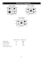
OPERATION MANUAL
Gas Cooktop
CGA 60 WOK, CGA 75 WOK, CGA 90 WOK
COD. 208196 - REV 2 - 07.06.2006
Congratulations on the purchase of your AEG appliance.
We are sure it will provide many years of great cooking experience.
You may find that it has different features and characteristics to your last appliance.
It is essential you read this operation manual thoroughly to fully understand all of the various functions
and operations. Experiment with your cooking and take advantage of the features your new appliance
offers.
This manual should be retained for future reference. Should ownership of the appliance be transferred,
please ensure that the manual is also passed onto the new owner.
Contents
A-
Installation check and warnings
Page 3
B-
Cooking Instructions
Page 4
C-
Cleaning
Page 5
D-
Installation & Warnings
Page 6
E-
Technical Diagrams
Page 9 - 10
F-
Technical Characteristics Table
Page 9
G-
Warranty
Page 11
2
A-
Installation check and warnings
We invite you to read this instruction booklet carefully, before installing and using the equipment.
If this equipment should be sold or transferred to another person, please ensure that the new
user receives this booklet.
This appliance complies with the following Directives:
EEC 90/396 (Gas)
EEC 73/23 e 93/68 (Low Voltage)
EEC 89/336 (Electromagnetic Compatibility)
EEC 89/109 (Contact with foods)
NOTE:
– The installation must be carried out by experienced and qualified personnel, in conformity with the
regulations in force.
– The equipment has been designed to be used by adults only. Please monitor children closely when
they’re near the appliance to ensure their safety.
– Before powering the equipment, check that it is properly adjusted for the type of gas at disposal.
– Before carrying out the maintenance or cleaning the equipment, cut power supply off and make it cool
down.
– Make sure that air circulates around the gas equipment. Insufficient ventilation produces a lack of oxygen
resulting in possible malfunctions.
– In case of an intense or prolonged use of the equipment, it may be necessary to improve aeration.
– The products of combustion must be discharged outside through a suction hood or an electric fan.
– For any possible modification, apply to an authorized Technical Assistance Centre and demand original
spare parts.
WARNING:
If the appliance is equipped with a glass cover turn off all the burners and wait a few minutes before
closing the cover.
The manufacturer refuses all responsibility for possible damages to things or people, resulting
from incorrect installation or from an incorrect, improper or unreasonable use of the appliance.
3
B-
Cooking Instructions
NOTE:
Automatic start-up without valves
Turn the corresponding knob anti-clockwise up
to the maximum position (large flame, Fig. 1) and
press start-up button P(fig. 1).
When the equipment is switch off, always check
that the knobs are in the closing position.
If the flame should blow out accidentally, the
safety valve will automatically stop the gas supply,
after a few seconds. To restore operation, set the
knob to the lighting point (large flame, fig. 1) and
press. While cooking with fat or oil, pay the utmost
attention as these substances can catch fire when
overheated.
Automatic start-up with valves
Turn the corresponding knob anticlockwise up
to the maximum position (large flame, fig. 1) and
press the knob.
Once the burner has been started up, keep the
knob pressed for about 6 seconds.
WARNING:
– Do not use sprays near the appliance in operation.
– Do not place unstable or deformed pots on the
burner, so as to prevent them from overturning or
overflowing.
– Always turn gas off if moving a pot away from the
appliance.
Using the burners
In order to obtain the maximum yield without
wasting gas, it is important that the diameter of
the pot is suitable for the burner potential (see
the following table). This is to avoid the flame
extremities being larger than the base of the pot.
All of the operating positions must be chosen
between the maximum and the minimum ones,
never between the minimum position and the
closing point.
The gas supply can be interrupted by turning the
knob clockwise up to the closing position.
NOTE:
If there is no power supply, it is possible to light the
burners with matches, setting the knob to the startup point (large flame, fig. 1).
BURNERS
POWER (MJ/h)
POWER (Btu/h)
Ø of pots
Auxiliary
3.2
3000
10 - 14 cm
Semi-rapid
6.3
6000
16 - 18 cm
Rapid
11.6
11000
20 - 22 cm
Wok
17.9
17000
24 - 26 cm
4
C-
Cleaning
WARNING:
– Before any operation, disconnect the appliance
from the electric grid.
– Do not clean the appliance while it is hot.
Burners and racks
These parts can be removed to make cleaning
easier.
The burners must be washed with a sponge and
soapy water or with a light detergent, wiped well
and placed in their housing perfectly.
After cleaning, check that the feeler of the safety
valve, start-up electrode and the flame-dividing
ducts are not clogged with soap or grime.
The racks can be washed in the dishwasher.
Enameled Burner Caps
The enameled burner caps must be washed with a
sponge and soapy water or with a light detergent.
WARNING:
– Do not use abrasive or corrosive products.
– Do not leave substances, such as lemon or tomato
juice, salt water, vinegar, coffee and milk on the
enameled surfaces for a long time.
Gas taps
WARNING:
Lubrication of the gas taps must be carried out by
specialized personnel, exclusively.
In case of hardening or malfunctions in the gas
taps, apply to the Customer Service.
Stainless Steel
The stainless steel parts should also be cleaned
with soapy water and then dried with a soft cloth.
WARNING:
– Stainless steel can be stained if it remains in
contact with highly calcareous water or aggressive
detergents for an extended period of time.
– Stainless Steel can also discolour if in contact with
excessive heat.
5
D-
Installation & Warnings
with a cross section of at least 200cm2, and the
higher air exiting with a cross section of at least
60 cm2.
NOTE:
THE OPERATIONS INDICATED BELOW MUST
BE FOLLOWED BY QUALIFIED PERSONNEL
EXCLUSIVELY, IN CONFORMITY WITH THE
REGULATIONS IN FORCE.
THE MANUFACTURING FIRM REFUSES ALL
RESPONSIBILITY FOR DAMAGES TO PEOPLE,
ANIMALS OR OBJECTS, RESULTING FROM
THE FAILURE TO COMPLY WITH SUCH
PROVISIONS.
Fastening the top
Every cook-top is equipped with a special washer
and a set of hooks for mounting the cook-top.
Once the cut-out is made in the cabinet surface,
the installation procedure is as follows:
– Remove the trivets and complete burners from
the top.
– Turn the appliance upside down and lay the ‘S’
washer along the external border (fig. 5).
– Place the cook-top in the hole made in the piece
of furniture then block it with the V screws of the
fastening hooks G (fig. 6 / 6A).
The appliance is designed to be embedded into
heat-resistant cabinetry.
Cut a hole in the top of the cabinetry, with the
dimensions indicated in fig. 3, at a distance of
at least 50 mm from the appliance border to the
adjacent walls.
NOTE:
This appliance is not provided with a device for
exhausting the products of combustion.
Please check your local regulations to ensure
installation is in conformity.
WARNING:
– The surrounding cabinetry must resist a minimum
temperature of 75°C.
– The equipment must not be installed near
inflammable materials, such as curtains, cloths,
etc.
Gas Connection
Make sure that the appliance is adjusted for the
gas type available in your area (see the label under
the appliance). Follow the instructions indicated in
the chapter “gas transformations and adjustments”
for the possible adaptation to different gases.
The appliance must be connected to the gas
system by means of still metal pipes or flexible
steel pipes having continuous walls, in compliance
with the regulations in force in your area. Some
models are equipped with cylindrical A and conical
B connectors for gas supply (fig. 7).
( Ref to Fig. 3 on page 8)
MODEL
L (mm)
P (mm)
600-750
560
490
900
820
490
If the are any over-head cabinets above the
cooktop they must be a minimum of 762 mm (30")
higher. The distance on the left and on the right
side from lateral wall should be at least 110 mm
(4.5”), while the distance from the back wall should
be at least 25 mm (1”).
It is advisable to isolate the appliance from the
piece of furniture below with a separator, leaving a
depression space of at least 10 mm (fig. 4).
If the hob is going to be installed above an oven,
precautions must be taken to guarantee installation
is in accordance with current accident prevention
standards. Pay particular attention to the position
of the electric cable and gas pipe: they must not
touch any hot parts of the oven.
WARNING:
The connection must not stress the gas ramp.
Electric connection
The connection to the electric grid must be carried
out by qualified personnel and in conformity with
the regulations in force in your area.
The voltage of the electric system must correspond
to the value indicated in the label under the
appliance. Make sure that the electric system is
provided with an effective ground connection in
compliance with the regulations and provisions of
the law.
Grounding is compulsory.
WARNING:
If the hob is going to be installed on the top of a
built in oven without forced cooling ventilation,
proper air vents must be installed to guarantee an
adequate ventilation, with the lower air entering
6
D-
Installation & Warnings
GAS TRANSFORMATIONS AND ADJUSTMENTS
MAINTENANCE
Lubricating the taps
In the case of tap hardening, it is necessary to
disassemble the tap and grease it.
– Unscrew the two screws that lock the head flange
of the tap.
– Lift the gas adjusting cone and carefully clean it
with gasoline or diluent.
– Spread a little high-temperature grease on it,
making sure that the gas holes are not obstructed.
– Reassemble all of the parts with care.
Replacing the nozzles
If the equipment is adjusted for a type of gas that is
different from the original, it is necessary to replace
the burner nozzles as well. The nozzles used to
replace the original must be in accordance with the
table of the technical characteristics enclosed.
To remove the racks and burners by means of a
straight spanner ‘L’, unscrew the nozzle ‘U’ (Fig.8)
and substitute it with the corresponding one and
tighten the nozzle.
Replacing the power supply cable
If the power supply cable needs to be replaced,
it is necessary to use a cable with a section of
3x0.75mm2, type H05VV-F or H05RR-F, complying
with the regulations in force.
Adjusting the burners
The flame should always stay alight when the
burner is switched on, even if there is an abrupt
shift from the maximum to minimum flame position.
If the flame does not stay alight, adjust it as
follows:
– Start the burner
– Turn the tap up to the minimum position (small
flame)
– Remove the knob from the tap rod
– Using a flat-tip screwdriver ‘C’ into the hole ‘F’ of
the tap (fig.9) turn the by-pass screw up.
NOTE:
The connection to the terminal board must be
effected as shown in fig. 10 - 10A:
Brown cable L (phase)
Blue cable N (neutral)
Green-yellow cable (ground)
7
1
2
3
4
5
6A
7
6
8
10
9
8
10/A
E-
Technical Diagrams
CGA 60 WOK
CGA 75 WOK
CGA 90 WOK
F-
Technical Characteristics Table
BURNERS
N°
DESCRIPTION
1
RAPID
2
SEMI-RAPID
3
AUXILIARY
4
WOK
GAS
NORMAL
PRESSURE
INJECTOR
DIAMETER
TAPE BY
PASS
DIAMETER
NOMINAL
HEAT INPUT
MAX.
mbar
1/100 mm
1/100 mm
MJ/h (Btu/h)
PROPANE
28
92
42
NATURAL
10
155
REG.
PROPANE
28
72
31
NATURAL
10
120
REG.
PROPANE
28
55
27
NATURAL
10
90
REG.
PROPANE
28
107
60
NATURAL
10
175
REG.
11.6 (11000)
6.3 (6000)
3.2 (3000)
17.9 (17000)
The manufacturing firm refuses all responsibility for any possible imprecision in this booklet, due to
misprints or clerical errors. It reserves the right to make all the changes that it will consider necessary in
its own products, without affecting the essential characteristics of functionality and safety.
9
E-
Technical Diagrams
CGA 60 WOK
CGA 75 WOK
CGA 90 WOK
POWER (MJ/h)
POWER (Btu/h)
1 Rapid burner
11.6
11000
2 Semi-rapid burner
6.3
6000
3 Auxiliary burner
3.2
3000
4 Triple ring burner
17.9
17000
8 Control knob for burner
10
G-
Warranty
AEG products are designed and built to the highest standards.
We expect your appliances to provide many years of trouble free enjoyment.
In the event of an appliance requiring attention, each appliance is covered by a 2 year warranty from the
date of purchase.
Refer to warranty policy for complete terms and conditions.
Coverage is for costs of parts and labor for appliances in capital cities & metropolitan areas. We reserve
the right to charge directly for handling expenses outside the metropolitan region.
AEG products are supported by a national service support system.
Call our customer service department for attention.
Please retain your AEG invoice to quote should you require service assistance. This will identify
your product for our priority service back-up. Please attach your invoice to this manual for easy
future reference.
AEG
Unit 20,
2150 Winston Park Drive,
Oakville, Ontario,
Canada L6H5V1
Tel 905-829.3980
Fax 905-829.3985
email: [email protected]
For Service & Spares:
EURO-PARTS
1-800.678-8352
Important: Please record details of your purchase below and mail or fax to AEG:
-------------------------------------------------------------- cut along line ---------------------------------------------------------
Name:____________________________
Tel n° ______________________________________
Address: ____________________________________________________________________________
City: __________________________
State:_______________
Zip Code: __________________
Where purchased: ________________________________________ Purchase date : ______________
Items purchased: _____________________________________________________________________
Serial No. (s): ________________________________________________________________________
11
AEG
Unit 20,
2150 Winston Park Drive,
Oakville,Ontario,
Canada L6H5V1
Tel 905-829.3980
Fax 905-829.3985
email: [email protected]
For Service & Spares:
EURO-PARTS
1-800.678-8352