1
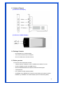
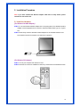
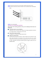
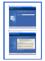
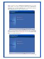
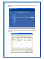
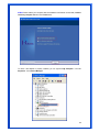
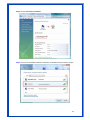
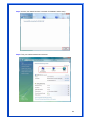
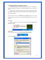
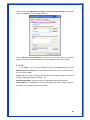
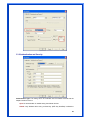
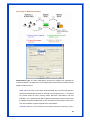
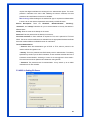
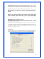
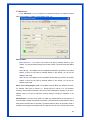
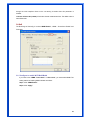
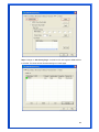
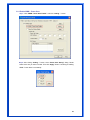
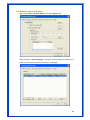
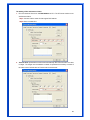
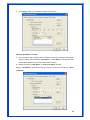
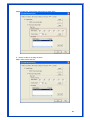
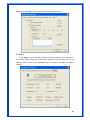
802.11g, 54Mbps
MIMO PCI Wireless Adapter
User’s Manual
Model # AWN-MIMO-54RA
FCC Warning
This equipment has been tested and found to comply with the limits for a Class B digital device,
pursuant to part 15 of the FCC Rules. These limits are designed to provide reasonable
protection against harmful interference in a residential installation. This equipment generates,
uses, and can radiate radio frequency energy and, if not installed and used in accordance with
the instructions, may cause harmful interference to radio communication. However, there is no
guarantee that interference will not occur in a particular installation. If this equipment does
cause harmful interference to radio or television reception, which can be determined by turning
the equipment off and on, the user is encouraged to try to correct the interference by one or
more of the following measures:
-
Reorient or relocate the receiving antenna.
-
Increase the separation between the equipment and receiver.
-
Connect the equipment into an outlet on a circuit different from that to which
-
Consult the dealer or an experienced radio/TV technician for help. the receiver is
connected.
FCC Caution: Any changes or modifications not expressly approved by the party responsible
for compliance could void the user’s authority to operate this equipment.
This device complies with Part 15 of the FCC Rules. Operation is subject to the following two
conditions: (1) This device may not cause harmful interference, and (2) this device must
accept any interference received, including interference that may cause undesired operation.
IMPORTANT NOTE:
FCC Radiation Exposure Statement:
This equipment complies with FCC radiation exposure limits set forth for an uncontrolled
environment. This equipment should be installed and operated with a minimum distance of
about eight inches (20cm) between the radiator and your body.
This transmitter must not be co-located or operated in conjunction with any other antenna or
transmitter.
CE Mark Warning
This is a Class B product. In a domestic environment, this product may cause radio
interference, in which case the user may be required to take adequate measures.
Copyright
2006 All Rights Reserved. No part of this document can be copied or reproduced in any form
without written consent from the company.
1
Revision History
Revision
History
V1.1
Second release
All brand and product names mentioned in this manual are trademarks and/or registered
trademarks of their respective holders.
2
Contents
1.
2.
Introduction ............................................................................ 4
1.1
Features ......................................................................... 4
1.2
LED Indicator ................................................................. 4
1.3
Hardware Diagram ......................................................... 5
1.4
Package Contents........................................................... 5
1.5
Before you start ............................................................. 5
Installation Procedure............................................................. 6
2.1 Install the Hardware ........................................................ 6
2.2 Install the Driver & Utility ................................................ 8
2.2.1 For Windows XP/2000/ME/98SE ................................... 8
2.2.2 For Windows Vista (x86 & x64 bit)................................13
3. Wireless Network Configuration Utility.................................... 19
3.1
Profile .......................................................................... 20
3.2
Link Status ................................................................... 21
3.3
Site Survey ................................................................... 22
3.3.1 Configure the Profile .....................................................23
3.3.2 Authentication and Security ..........................................25
3.3.3 802.1x Setting-Certification ..........................................27
3.3.4 802.1x Setting-CA Server ..............................................29
3.4
Statistics ...................................................................... 30
3.5
Advanced ..................................................................... 31
3.6
QoS .............................................................................. 33
3.6.1 Configure to enable Wi-Fi Multi-Media ...........................33
3.6.2 Enable WMM – Power Save............................................35
3.6.3 Enable DLS (Direct Link Setup) .....................................36
3.7
4.
About ........................................................................... 40
Troubleshooting .................................................................... 41
3
1. Introduction
This adapter is an IEEE 802.11g client device that delivers unrivaled wireless
performance for your desktop PC or laptop PC. With this adapter, you can easily upgrade your
computer wireless connectivity. Once connected, access your high-speed Internet connection
while sharing photos, files, music, video, printers, and storage. Get a better Internet
experience with a faster wireless connection so you can enjoy smoother digital phone calls,
gaming, downloading, and video streaming. It provides peer-to-peer communication among
any compatible wireless users and no Access Point required. This adapter offers easy
installation and cost-effective connection for corporate, SOHO and residential users.
This Wireless LAN adapter uses Ralink (MIMO XRTM ) chipset solution and provides
maximum data transfer rate up to 54 Mbps. This adapter supports WEP Data Encryption, WPA
and WPA2 high-level WLAN security features that guarantee the best security for users.
This product is made in ISO9001 approved factory and complies with FCC part 15
regulations and CE approval.
1.1 Features
• Compatible with IEEE 802.11g standard and maximum data transfer rate up to 54Mbps
• Increase Speed and Coverage by MIMO XRTM and Packet-OVERDRIVETM Technology
• Dynamic date rate scaling at 54, 48, 36, 24, 18, 12, 9 and 6Mbps for 802.11g
• Dynamic date rate scaling at 11, 5.5, 2 and 1Mbps for 802.11b
• Maximum reliability, throughput and connectivity with automatic data rate switching
• Supports 64/128-bit WEP Data Encryption, WPA, WPA2 and 802.11i security
• Supports both Infrastructure and Ad-Hoc Peer-to-Peer Networking Modes
• Supports Quality of Service (QoS), 802.11e, WMM
• Range extension by using external antenna
• Simple user setup and diagnostics utilities
• Low power with Advanced Power Management
• Support 32-bit PCI interface slot for Desktop PC (for WLAN PCI adapter)
• Support 32-bit Cardbus interface for Laptop PC (for WLAN Cardbus adapter)
1.2 LED Indicator
LED
Light Status
ACT / LINK
Flashing
On
Description
Wireless LAN has Activity (ACT) data being sent.
Wireless LAN has been activated.
4
1.3 Hardware Diagram
[For Wireless PCI Adapter]
[For Wireless CardBus Adapter]
1.4 Package Contents
• One Wireless PCI or Cardbus adapter
• Three external antennas (for PCI adapter)
• One CD includes driver and user’s manual
1.5 Before you start
You must have the requirements as follow,
• A laptop computer / desktop PC with an available 32-bit Cardbus / PCI slot
• At least a 300MHz processor and 32MB memory
• Windows 98SE/ME/2000/XP/XP-64bit/Vista 32bit/Vista 64bit support
• A CD-ROM drive
• PCI / Cardbus controller properly installed
• An IEEE802.11g or IEEE802.11b Access Point (for Infrastructure mode) or another
IEEE802.11g or IEEE802.11b wireless adapter (for Ad-Hoc Networking Mode)
5
2. Installation Procedure
Note: If you have installed the Wireless Adapter LAN driver & utility before, please
uninstall the old version first.
2.1 Install the Hardware
[For Wireless CardBus Adapter]
STEP1: To use the Wireless Cardbus Adapter with a computing device, the Wireless Cardbus
Adapter must be equipped with an internal or external PCMCIA Card Type II or Type III
slot.
STEP2: Please firmly insert the Wireless Cardbus Adapter into an available PCMCIA Card
slot. PCMCIA Card slot is located on one side of the Laptop PC.
[For Wireless PCI Adapter]
STEP1: Turn off your computer and remove its cover
STEP2: Insert the PCI card to an available PCI slot firmly. Please refer to the illustration below:
6
STEP3: Secure this card to the rear of the computer chassis and put back the cover.
STEP4: Secure the antenna to antenna connector of the card. Please refer to the illustration
below:
STEP5: Turn on the computer.
[Guidelines for the Hardware Installation]
Please observe the following guidelines when you are installing the PCI card to the
Desktop PC:
Avoid placing the PC close to obstacles
Obstructions such as concrete and thick walls limit radio signal penetration and reduce
the throughput and the coverage range of the PCI card.
Place the PC as high as possible
The higher the PC is placed, the better the performance.
Adjust the antenna position
The WLAN PCI card has two antennas for signal reception and one antenna for high
power signal transmission. The antennas on the right and left side are for signal
reception and should be set perpendicular (90 degrees) to each other. The central one is
for signal transmission and should be pulled up about 45 degree. Please refer to the
illustration below:
7
2.2 Install the Driver & Utility
2.2.1 For Windows XP/2000/ME/98SE
Note: The following installation was operated under Windows XP. (Procedures will be
same for Windows 2000 / Windows ME / Windows 98SE)
STEP1: Found New Hardware Wizard is displayed after the adapter is installed and the
computer is restarted. Please click Cancel to continue.
STEP2: Insert Installation CD into CD-ROM drive then windows below will appear. Click
Install Driver to begin device driver installation.
8
STEP3: Please wait for a while during the Setup Wizard is preparing the setup.
STEP4: Please read the following license agreement. Use the scroll bar to view the rest of this
agreement. Click Yes to accept the agreement.
9
STEP5: In Windows XP, there is a Windows Zero Configuration Tool for you to setup
wireless adapter. You can choose to configure the adapter through the Microsoft Zero
Configuration Tool or the Ralink Configuration Tool. It is recommended to choose the
Ralink Configuration Tool for the adapter. Click Next to continue.
STEP6: If you need the adapter to operate with better performance, place choose Optimize
for performance mode to enable the Tx Burst mode. Or you can choose Optimize for WiFi
mode to run in standard wireless network.
10
STEP7: Please wait for a while during the adapter is configuring your new software
installation.
STEP8: When the adapter is installed properly, the configuration utility will be displayed
automatically.
11
STEP9: Please restart your computer after the installation has finished. Choose Yes, I want to
restart my computer now and click Finish button.
To check if the adapter is properly installed, you can right-click My Computer Æ choose
Properties Æ click Device Manager.
12
The Configuration Utility appears as an icon on the system tray of Windows while the
adapter is running. You can open the utility by double-click on the icon.
Right-click the icon, there are some items for you to operate the configuration utility,
z
Launch Config Utilities Æ Select this option to open the Configuration Utility tool.
z
Use Zero Configuration as Configuration utilityÆ Select this option to use Windows
XP built-in wireless configuration utility (Windows Zero Configuration) to configure to
card.
z
Switch to AP Mode
z
Exit Æ Select Exit to close the Configuration Utility tool.
2.2.2 For Windows Vista (x86 & x64 bit)
Step1: Update Driver Software – Network Controller is displayed after the adapter is
installed and the computer is restarted. Please click Cancel to continue.
13
Step2: Insert Installation CD into CD-ROM drive then windows below will appear. Click Install
Driver to begin device driver installation
Step3: Please wait for while during Wireless LAN Card is configuring your new software
installation.
14
Step4: After Wireless Network Card has finished installing, click “Finish” to exit the setup
wizard.
Step5: To check if the adapter is properly installed, you can right-click My Computer Æ
choose Properties Æ click Device Manager
15
[To setup Wireless Network in Windows Vista Operation System]
Step1: Start Î All Programs Î Control Panel
Step2: Choose “Network and Sharing Center”
16
Step3: Choose “Connect to a network”
Step4: From the list of available networks, choose one of networks which you want to connect.
17
Step5: And then, the network has been connected. Click Close to exit the setup.
Step6: Final, your wireless network has connected.
18
3. Wireless Network Configuration Utility
The Configuration Utility is a powerful application that helps you to configure the
Wireless LAN adapter and monitor the link status and statistics during the communication
process.
When the adapter is installed, the configuration utility will be displayed automatically.
This adapter will auto connect to wireless device which has better signal strength and no
wireless security setting.
Note: In Windows XP, there is a “Windows Zero Configuration Tool” for you to setup
wireless clients. If you want to switch the configuration utilities, please follow one of the ways
as below:
[First Way]
Right-click the icon in the system tray and select Use Zero Configuration as
Configuration utility
[Second Way]
STEP1: Right-click the icon and select “View Available Wireless Networks”
STEP2: Click “Advanced” as below,
19
STEP3: Uncheck “Use Windows to configure my wireless network settings” to enable the
utility for the adapter and then click OK to continue.
Note: If “Wireless Zero Configuration” is enabled, you can only configure the advance
setting or check the link status and statistics from the configuration utility of the adapter.
3.1 Profile
In the “Profile”, you can view and manage the current using Available Point(s). You can
Add, Delete, Edit, or Activate the current Available Point(s). Also you can duplicate the AP or
set current AP as Default.
Profiles List: The Profiles List displays all the profiles and the relative settings of the profiles
including Profile Name, SSID, and Channel…etc.
Add/Delete/Edit Button: Click these buttons to add/delete/edit the selected profiles.
Activate Button: Click ”Activate” to connect the selected profile. When a profile is activated,
the adapter will be initially connected to the profile.
20
3.2 Link Status
In this section, you can immediately monitor the current connected link status, such as
Link Speed, Throughput, Link Quality, Signal Strength, Noise Level …etc.
Status: Display the SSID and MAC ID of the network that the adapter is connecting to.
Extra Info: Display the link status.
21
Channel: Display the number of the radio channel and the frequency used for the networking.
Link Speed (Mbps): Display the transmission and reception rate of the network. The
maximum transmission rate is 54Mbps.
Throughput (Kbits/sec): Display the speed of data transmitted and received.
Link Quality: This bar indicates the quality of the link. The higher the percentage, the better
the quality.
dBm: If you want to know the signal strength in the unit of dBm, select the check box.
Signal Strength: This bar shows the signal strength level. The higher percentage shown in
the bar, the more radio signal been received by the adapter. This indicator helps to find the
proper position of the wireless device for quality network operation.
Signal Strength2: This card shows two antennas for receiving. The “Signal Strength2”
indicates the receiving signal strength for the second antenna.
Noise Level: Display the noise level in the wireless environment.
3.3 Site Survey
When you open the Configuration Utility, the system will scan all the channels to find all
the access points/stations within the accessible range of your adapter and automatically
connect to the wireless device with the highest signal strength. From the “Site Survey”, all the
network nearby will be listed. You can change the connection to another network or add one of
the networks to your own profile list.
Available Network: This list shows all available wireless networks within range of your
adapter. It also displays the information of the networks including the SSID, BSSID, Signal
22
Strength, Channel, Encryption, Authentication, and Network Type. If you want to connect to
any networks on the list, double-click the item on the list, and the card will automatically
connect to the selected network.
Rescan Button: Click this button to collect the SSID and Channel information of all the
wireless devices nearby.
Connect Button: Click this button to connect to the selected network.
Add to Profile: Add the selected network to Profile list.
3.3.1 Configure the Profile
If you want to add one Access Point to the profile, click “Add to Profile” button. And
then the Add Profile windows will display as follow. You can configure your Wireless Network
Security for the card.
Profile Name: Define a recognizable profile name for you to identify the different network.
SSID: The SSID (up to 32 printable ASCII characters) is the unique name identified in a WLAN.
The ID prevents the unintentional merging of two co-located WLANs. You may specify a SSID
for the adapter and then only the device with the same SSID can interconnect to the adapter. If
you want to add the network nearby to the profile list, pull down the menu, the entire network
will be listed for you to add one of them to the profile list.
PSM (Power Saving Mode): The power saving function is only available when the network
type is in Infrastructure mode.
CAM (Constantly Awake Mode) – The adapter will always set in active mode.
23
PSM (Power Saving Mode) – Enable the adapter in the power saving mode when it is
idle.
Network Type:
Infrastructure – This operation mode requires the presence of a wireless Access Point.
All communication is done via the Access Point or Router.
Ad-Hoc – Select this mode if you want to connect to another wireless station in the
Wireless LAN network without through an Access Point or Router.
Tx Power: If you want to lower the transmit power of the adapter for saving the power of the
system, you can select the lower percentages from the list. The lower power will cause the
lower signal strength and the coverage range.
Ad Hoc Wireless Mode: When the card is set in Ad-Hoc (Peer-to-Peer Mode), you can
designate the wireless connection mode for the Ad-Hoc network.
802.11 B only – This adapter can be compatible with both 802.11g and 802.11b wireless
stations. If there are only 802.11b wireless stations in the network, you can set the card
to this mode.
802.11 B/G mix – If you have a mix of 802.11b and 802.11g wireless stations in your
network, it is recommended to setting the card to this mode. This mode is also the default
setting.
802.11 G only –This card can be compatible with both 802.11g and 802.11b wireless
stations. If there are only 802.11g wireless stations in the network, you can set the card
to this mode.
Preamble: The preamble defines the length of the CRC block for communication among
wireless devices. This option is only active in the Ad Hoc network. There are two modes
including Auto and Long Preamble. If “Auto” mode is selected, the adapter will auto switch
the preamble mode depending on the wireless devices is connecting to.
RTS Threshold: Minimum packet size required for an RTS (Request To Send). For packets
smaller than this threshold, an RTS is not sent and the packet is transmitted directly to the
wireless network. Select a setting within a range of 0 to 2347 bytes. Minor change is
recommended.
Fragment Threshold: The value defines the maximum size of packets; any packet size larger
than value will be fragmented. If you have decreased this value and experience high packet
error rates, you can increase it again, but it will likely decrease overall network performance.
Select a setting within a range of 256 to 2346 bytes. Minor change is recommended.
Channel: This setting is only available for Ad Hoc mode. Select the number of the radio
channel used for the networking. The channel setting should be the same with the network you
are connecting to.
24
3.3.2 Authentication and Security
Authentication Type: This setting has to be consistent with the wireless networks that the
adapter intends to connect.
Open: No authentication is needed among the wireless devices.
Shared: Only Wireless device using a shared key (WEP Key identified) is allowed to
25
connecting each other. Setup the same key as the wireless device that the adapter
intends to connect.
LEAP: LEAP is a pre-EAP, Cisco-proprietary protocol, with many of the features of EAP
protocols. Cisco controls the ability of other vendors to implement this protocol, so it
should be selected for server products are not a concern. When you have set up LEAP
authentication, you have to enter the use name and password of your computer.
WPA: WPA provides a scheme of mutual authentication using either IEEE
802.1x/Extensible Authentication Protocol (EAP) authentication or pre-shared key (PSK)
technology. It provides a high level of assurance to enterprise, small business and home
users that data will remain protected and that only authorized users may access their
networks. For enterprises that have already deployed IEEE 802.1x authentication, WPA
offers the advantage of leveraging existing authentication databases and infrastructure.
WPA-PSK – It is a special mode designed for home and small business users who do
not have access to network authentication servers. In this mode, known as Pre-Shared
Key, the user manually enters the starting password in their access point or gateway, as
well as in each wireless station in the network. WPA-PSK takes over automatically from
that point, keeping unauthorized users that don’t have the matching password from
joining the network, while encrypting the data traveling between authorized devices.
WPA2 – Like WPA, WPA2 supports IEEE 802.1x/EAP authentication or PSK technology.
It also includes a new advanced encryption mechanism using the Advanced Encryption
Standard (AES). AES is required to the corporate user or government users. The
different between WPA and WPA2 is that WPA2 provides data encryption via the AES. In
contrast, WPA uses Temporal Key Integrity Protocol (TKIP).
WPA2-PSK – WPA2-PSK is also for home and small business. The difference between
WPA-PSK and WPA2-PSK is that WPA2-PSK provides data encryption via the AES. In
contrast, WPA-PSK uses Temporal Key Integrity Protocol (TKIP).
WPA 802.1X – 802.1x authentication is required in WPA. In the 802.11 standard, 802.1x
authentication was optional.
WPA2 802.1X – WPA2 is the next-generation Wi-Fi security standard, combining the
most powerful authentication and encryption techniques to protect wireless networks
from unauthorized use. Based upon the recently ratified IEEE 802.11i standard, WPA2
adds the Advanced Encryption Standard (AES) to the original WPA specification to
provide the greatest levels of network security available. The National Institute of
Standards and Technology (NIST) advocate the use of AES security to protect sensitive
digital information on government networks.
802.1x Setting: When you have set the Authentication Type to Open, Shared, WPA or WPA2,
you can also enable IEEE 802.1x setting to use the authentication server or certification server
to authenticate client users.
26
Encryption Mode:
None – Disable the Encryption mode.
WEP – Enabled the WEP Data Encryption. When the item is selected, you have to
continue setting the WEP Key Length & the key Index.
TKIP – TKIP (Temporal Key Integrity Protocol) changes the temporal key every 10000
packets (a packet is a kind of message transmitted over a network). This insures much
greater security than the standard WEP security.
AES – AES has been developed to ensure the highest degree of security and
authenticity for digital information and it is the most advanced solution defined by IEEE
802.11i for the security in the wireless network.
Note: All devices in the network should use the same encryption method to ensure the
communication.
WPA Pre-Shared Key: The WPA-PSK key can be from 8 to 64 characters and can be letters
or numbers. This same key must be used on all of the wireless stations in the network.
WEP Key (Key1~Key4): The WEP keys are used to encrypt data transmitted in the wireless
network. There are two types of key length: 64-bit & 128-bit. Select the default encryption key
form key1 to key4 by selected the radio button.
Fill the text box by following the rule below:
64-bit – Input 10-digit Hex values (in the “A-F”, “a-f, and “0-9” range) or 5-digit ASCII
characters (including “a-z” and “0-9”) as the encryption keys. For example: “0123456aef”
or “test1”
128-bit – Input 26-digit Hex values (in the “A-F”, “a-f, and “0-9” range) or 13-digit ASCII
characters (including “a-z” and “0-9”) as the encryption keys. For example:
“01234567890123456789abcdef” or “administrator”
3.3.3 802.1x Setting-Certification
The IEEE 802.1X specification describes a protocol that can be used for authenticating
both clients and servers on a network. The authentication algorithms and methods are those
provided by the Extensible Authentication Protocol (EAP), a method of authentication that has
been in use for a number of years on networks that provide Point-to-Point Protocol (PPP)
support as many Internet service providers and enterprises do.
When an AP acting as an authenticator detects a wireless station on the LAN, it sends an
EAP-Request for the user’s identity to the device. (EAP, or the Extensible Authentication
Protocol, is an authentication protocol that runs before network layer protocols transmit data
over the link) In turn, the device responds with its identity, and the AP relays this identity to an
authentication server, which is typically an external RADIUS server.
27
[An example for MD5 Authentication]
Authentication Type: The EAP authentication protocols this adapter has supported are
included as follows. This setting has to be consistent with the wireless APs or Routers that the
adapter intends to connect.
PEAP and TTLS: PEAP and TTLS are similar and easier than TLS in that they specify a
stand-alone authentication protocol be used within an encrypted tunnel. TTLS supports
any protocol within its tunnel, including CHAP, MS-CHAP, MS-CHAPv2, PAP and
EAP-MD5. PEAP specifies that an EAP-compliant authentication protocol must be used;
this adapter supports EAP-MSCHAP v2, EAP-TLS/Smart card and Generic Token Card.
This client certificate is optional required for the authentication.
TLS/Smart Card: TLS is the most secure of the EAP protocols but not easy to use. It
28
requires that digital certificates be exchanged in the authentication phase. The server
presents a certificate to the client. After validating the server’s certificate, the client
presents a client certificate to the server for validation.
MD5-Challenge: MD5-Challenge is the easiest EAP type. It requires the wireless station
to enter a set of user name and password as the identity to RADIUS Server.
Session
Resumption:
There
are
“Disabled”,
“Reauthentication”,
“Roaming”,
“SameSsid”, and “Always” selections for you to choose whether to recovery the session in
different status.
Identity: Enter the name as the identity for the server.
Password: Enter the password as the identity for the server.
Use Client Certificate: A client certificate is required for TLS, and is optional for TTLS and
PEAP. This forces a client certificate to be selected from the appropriate Windows Certificate
Store and made available to the RADIUS server for certification.
Tunneled Authentication:
-- Protocol: When the authentication type is PEAP or TTLS, select a protocol to be
used to build the encrypted tunnel.
-- Identity: This is the protected user EAP Identity used for authentication. The identity
specified may contain up to 63 ASCII characters, is case sensitive and takes the form of
a Network Access Identifier, consisting of <name of the user>@<user’s home realm>.
The user’s home realm is optional and indicates the routing domain.
-- Password: The password used for authentication. It may contain up to 63 ASCII
characters and is case sensitive.
3.3.4 802.1x Setting-CA Server
29
Use Certificate Chain: When the EAP authentication types such as TLS, TTLS or PEAP is
selected and required a certification to tell the client what server credentials to accept from the
authentication server in order to verify the server, you have to enable this function.
Certificate Issuer: Choose the server from the list to issue the certificate. If “Any Trusted
CA” is selected, any CA included in the list (provided by the Microsoft Certificate Store) is
permitted.
Allow Intermediate Certificates: A server designates an issuer as a trusted root authority by
placing the issuer’s self-signed certificate, which contains the issuer’s public key, into the
trusted root certification authority certificate store of the host computer. Intermediate or
subordinate certification authorities are trusted only if they have a valid certification path from a
trusted root certification authority.
Server Name: Enter the authentication server name.
Server name must match exactly: When selected, the server name must match exactly the
server name found on the certificate.
Domain name must end in specified name: When selected, the server name field identifies
a domain. The certificate must use a server name belonging to this domain or to one of its
sub-domains (e.g. zeelans.com, where the server is blueberry.zeelans.com) but it may be any
name used in the certificate name field.
3.4 Statistics
This option enables you to view the statistic information of the connection including transmit
statistics and receive statistics. You may reset the counters by clicking “Reset Counter”.
30
3.5 Advanced
In the “Advanced”, you can configure more advanced settings, for example: wireless
Mode, B/G Protection, Tx Rate, Country Region Code…etc.
Wireless Mode:
802.11 B/G mix – If you have a mix of 802.11b & 802.11g wireless stations in your
network, it is recommended to setting the card to this mode. This mode is also the default
setting.
802.11 B only – This adapter can be compatible with both 802.11g and 802.11b wireless
stations. If there are only 802.11b wireless stations in the network, you can set the
adapter to this mode.
802.11 G only –This adapter can be compatible with both 802.11g and 802.11b wireless
stations. If there are only 802.11g wireless stations in the network, you can set the
adapter to this mode.
Select Your Country Region Code: The available channel differs from different countries.
For example: USA (FCC) is channel 1-11, Europe (ETSI) is channel 1-13. The operating
frequency channel will be restricted to the country user located before importing. If you are in
different country, you have to adjust the channel setting to comply the regulation of the
country.
B/G Protection: If you have a mix of 802.11b & 802.11g wireless stations in the network, it is
recommended to enable the protection mechanism. This mechanism can decrease the rate of
data collision between 802.11b and 802.11g wireless stations. When the protection mode is
enabled, the throughput of the adapter will be a little lower due to many of frame traffic should
31
be transmitted.
Auto – Based on the status of network and automatically disable/enable protection
mode.
On – Always enable the protection mode.
Off – Always disable the protection mode.
Tx Rate: There are several options including Auto/1/2/5.5/6/9/12/18/24/36/48/54Mbps for you
to select. When the “Auto” is selected, the device will choose the most suitable transmission
rate automatically. The higher data rate you designated in the network, the shorter distance is
allowed between the card and the wireless stations.
When the wireless mode is “802.11 B only”, the maximum data rate is 11 Mbps (11b) so
that there are only “Auto/1/2/5.5/11Mbps” options you can select.
Tx BURST: The Burst enables the adapter to deliver the better throughput in the same period
and environment.
Enable TCP Window Size: The TCP Window is the amount of data a sender can send on a
particular connection before it gets an acknowledgment back from the receiver that it has
gotten some of it. When the Router or AP card is connecting to have set up the TCP Window,
you can enable the parameter to meet the data size for the Router or AP connection. The
larger TCP Window the better performance.
Fast Roaming at -70dBm: You can enable the parameter when you want to fast roaming to
the network nearby without intercepting the wireless connection, especially the adapter is
applied to the multimedia application or a voice call. The adapter will fast roaming to the near
network when the receive sensitivity (signal strength) is lower to the value you have set up.
Turn Off RF Button: If you want to turn off the radio of the adapter temporarily, click this
button. To turn on the radio, click this button again.
Enable CCX: CCX (Cisco Compatible Extensions) is developed by Cisco for the radio
monitoring and fast roaming.
Turn on CCKM: During normal operation, LEAP-enabled client devices mutually authenticate
with a new access point by performing a complete LEAP authentication, including
communication with the main RADIUS server.
When you configure your wireless LAN for fast re-association, however, LEAP-enabled
client devices roam from one access point to another without involving the main server. Using
Cisco Centralized Key Management (CCKM), and access point configured to provide Wireless
Domain Services (WDS) takes the place of the RADIUS server and authenticates the client so
quickly that there is no perceptible delay in voice or other time-sensitive applications.
Enable Radio Measurement: When this parameter is enabled, the Cisco AP can run the radio
monitoring through the associated CCX-compliant clients to continuously monitor the WLAN
radio environment and discover and new APs that are transmitting beacons.
Non-Serving Channel Measurements: The Cisco AP can perform monitoring measurements
32
through the CCX-compliant clients on the non-serving channels when this parameter is
enabled.
Limit xxx milliseconds (0-2000): It limits the channel measurement time. The default value is
250 milliseconds.
3.6 QoS
The QoS Page of RaConfig. It involves “WMM Enable”, “WMM – Power Save Enable” and
DLS setup.
3.6.1 Configure to enable Wi-Fi Multi-Media
If you want to use “WMM – Power Save” or “Direct Link”, you must enable WMM. The
setting method of enabling WMM indicates as follows:
Step1: Click “WMM Enable”
Step2: Click “Apply”.
33
Step3: Change to “Site Survey Page”. And add an AP that supports WMM features
to a Profile. The result will look like the below figure in Profile page.
34
3.6.2 Enable WMM – Power Save
Step1: Click “WMM – Power Save Enable”. And Click “Setting…” button.
Step2: After clicking “Setting…” button, show “Power Save Setting” dialog. Please
select which ACs you want to enable. Then click “Apply” button. The setting of enabling
WMM – Power Save is successfully.
35
3.6.3 Enable DLS (Direct Link Setup)
Step1: Click “Direct Link Setup Enable”. And Click “Apply” button
Step2: Change to “Site Survey Page”. And add an AP that supports DLS features to a
Profile. The result will look like the below figure in Profile page.
36
The Setting of DLS indicates as follow:
1. Fill in the blanks of Direct Link with MAC Address of STA. The STA must conform to two
conditions as follow:
Step1: Connect with the same AP that support DLS features.
Step2: Have to enable DLS.
2. Timeout Value represents that it disconnect automatically after some seconds. The value
is integer. The integer must be between 0~65535. It represents that it always connects if
the value is zero. Default value of Timeout Value is 60 seconds
37
3. Click “Apply” button. The result will look like the below figure.
Describe “DLS Status” as follow:
1. As the up figure, after configuring DLS successfully, show MAC address of the opposite
side and Timeout Value of setting in “DLS Status”. In “DLS Status” of the opposite side,
it shows MAC address of myself and Timeout Value of setting.
2. Display the values of “DLS Status” to “Direct Link Setup” as follow:
Step1: In “DLS Status”, select a direct link STA what you want to show it’s values in “Direct
Link Setup”.
38
Step2: Double click. And the result will look like the below figure.
3. Disconnect Direct Link Setup as follow:
Step1: Select a direct link STA.
39
Step2: Click “Tear Down” button. The result will look like the below figure.
3.7 About
In the “About”, you can click the hyperlink to connect the website for the information of
the wireless chipset vendor and review basic information about the Utility such as the
RaConfig Version, Driver Version, EEPROM Version, IP Address, Sub Mask, and Default
Gateway.
40
4. Troubleshooting
This chapter provides solutions to problems usually encountered during the installation and
operation of the adapter.
1. Symptom:
The LED is Off.
Possible Remedy:
Make sure the Wireless adapter is inserted properly. Otherwise, please contact your
vendor.
2. Symptom:
The LED is always on not blinking.
Possible Remedy:
Make sure that you have installed the driver from the attached CD.
3. Symptom:
The LED is blinking but the Wireless adapter icon does not appear in your icon tray.
Possible Remedy:
Make sure that you have installed the Utility from the attached CD.
4. Symptom:
The Wireless adapter is linking, but can’t share files with others.
Possible Remedy:
Make sure the File and printer-sharing function is enabled.
5. Symptom:
Slow or unstable performance.
Possible Remedy:
Try to change the channel of the communicating group or move your device closer to the
communicating device.
6. Symptom:
Can’t find the utility icon in the taskbar when plug in the Wireless adapter.
Possible Remedy:
You could enable the function by click the icon of Start Æ All Programs Æ Ralink Utility.
7. Symptom:
No wireless signal.
41
Possible Remedy:
Move the antennas of the access point or wireless router into an L shape (one vertically,
and one horizontally). Click on the Refresh button on the Site Survey screen. If the
computer still does not see the Access Point, and then try to move your Access Point
closer to the computer. Then click on the Refresh button again. If the computer still does
not see the Access Point, move all things that may cause interference with the wireless
signal.
8. Symptom:
If you still cannot get a wireless connection of the network.
Possible Remedy:
Step 1- Turn the computer off
Step 2- Turn the Access Point off
Step 3- Turn the Access Point on
Step 4- Wait 30 seconds
Step 5- Turn the computer back on
Step 6- Using the Utility reconnect to the Access Point:
Step 7- Double click on the bar graph icon in the system tray
Step 8- Select the Site Survey Link
Step 9- Highlight the SSID of your wireless network and click connect
Step 10- Click OK if all the settings are correct
9. What is the IEEE 802.11g standard?
802.11g is the new IEEE standard for high-speed wireless LAN communications that
provides for up to 54 Mbps data rate in the 2.4 GHz band. 802.11g is quickly becoming the
next mainstream wireless LAN technology for the home, office and public networks.
802.11g defines the use of the same OFDM modulation technique specified in IEEE
802.11a for the 5 GHz frequency band and applies it in the same 2.4 GHz frequency band
as IEEE 802.11b. The 802.11g standard requires backward compatibility with 802.11b.
The standard specifically calls for:
A. A new physically layer for the 802.11 Medium Access Control (MAC) in the 2.4 GHz
frequency band, know as the extended rate PHY(ERP(. The ERP adds OFDM as a
mandatory new coding scheme for 6, 12, and 24 Mbps (mandatory speeds), and 18, 36, 48,
54 Mbps (optional speeds). The ERP includes the modulation schemes found in 802.11b
including CCK for 11 and 5.5 Mbps and Barker code modulation for 2 and 1 Mbps.
B. A protection mechanism called RTS.CTS that governs how 802.11g devices and
802.11b devices interoperate.
42
10. What does IEEE 802.11 feature support?
The product supports the following IEEE 802.11 functions:
-- CSMA/CA Plus Acknowledge Protocol
-- Multi-Channel Roaming
-- Automatic Rate Selection
-- RTS/CTS Feature
-- Fragmentation
-- Power Management
11. What is Ad-Hoc?
An Ad-Hoc integrated wireless LAN is a group of computers, each has a Wireless LAN
adapter, Connected as an independent wireless LAN. Ad-Hoc wireless LAN is applicable at
a departmental scale for a branch or SOHO ope
ration.
12. What is Infrastructure?
An integrated wireless and wireless and wired LAN is called an Infrastructure configuration.
Infrastructure is applicable to enterprise scale for wireless access to central database, or
wireless application for mobile workers.
13. What is BSS ID?
A specific Ad hoc LAN is called a Basic Service Set (BSS). Computers in a BSS must be
configured with the same BSS ID.
14. What is WEP?
WEP is Wired Equivalent Privacy, a data privacy mechanism based on a 40 bit shared key
algorithm, as described in the IEEE 802.11 standard.
15. What is TKIP?
TKIP is a quick-fix method to quickly overcome the inherent weaknesses in WEP security,
especially the reuse of encryption keys. TKIP is involved in the IEEE 802.11i WLAN
security standard, and the specification might be officially released by early 2003.
16. What is AES?
AES (Advanced Encryption Standard), a chip-based security, has been developed to
ensure the highest degree of security and authenticity for digital information, wherever and
however communicated or stored, while making more efficient use if hardware and/or
43
software than previous encryption standards. It is also included in IEEE 802.11i standard.
Compare with AES, TKIP is a temporary protocol for replacing WEP security until
manufacturers implement AES at the hardware level.
17. Would the information be intercepted while transmitting on air?
WLAN features two-fold protection in security. On the hardware side, as with Direct
Sequence Spread Spectrum technology, it has the inherent security feature of scrambling.
On the software side, WLAN series offer the encryption function (WEP) to enhance security
and Access Control. Users can set it up depending upon their needs.
If you have any troubles to configure or setup this WLAN adapter, please feel free to
contact us.
Before contacting us, make sure collect following information. Submit complete detailed
information of your problem will help us to provide you accurate answers.
Model Name:
Serial Number:
PC Settings:
Other:
44