1
CHA
LLE
NG
ER
2009 CHALLENGER
2009
OWNER’S MANUAL
Chrysler LLC
81-226-0916
147914 Dodge LC22 Challenger.indd 1
Second Edition
Printed in U.S.A.
9/8/08 3:39:42 PM
VEHICLES SOLD IN CANADA
With respect to any Vehicles Sold in Canada, the name
Chrysler LLC shall be deemed to be deleted and the
name Chrysler Canada Inc. used in substitution therefor.
DRIVING AND ALCOHOL
Drunken driving is one of the most frequent causes of
accidents.
Your driving ability can be seriously impaired with blood
alcohol levels far below the legal minimum. If you are
drinking, don’t drive. Ride with a designated non-drinking
driver, call a cab, a friend, or use public transportation.
WARNING!
This manual illustrates and describes the operation of
features and equipment that are either standard or optional on this vehicle. This manual may also include a
description of features and equipment that are no longer
available or were not ordered on this vehicle. Please
disregard any features and equipment described in this
manual that are not on this vehicle.
Chrysler LLC reserves the right to make changes in
design and specifications, and/or make additions to or
improvements to its products without imposing any
obligation upon itself to install them on products previously manufactured.
Driving after drinking can lead to an accident. Your
perceptions are less sharp, your reflexes are slower,
and your judgment is impaired when you have been
drinking. Never drink and then drive.
Copyright © 2008 Chrysler LLC
SECTION
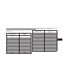
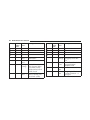
TABLE OF CONTENTS
PAGE
1
INTRODUCTION . . . . . . . . . . . . . . . . . . . . . . . . . . . . . . . . . . . . . . . . . . . . . . . . . . . . . . . . . . . . 3
1
2
THINGS TO KNOW BEFORE STARTING YOUR VEHICLE . . . . . . . . . . . . . . . . . . . . . . . . . . . . . .9
2
3
UNDERSTANDING THE FEATURES OF YOUR VEHICLE . . . . . . . . . . . . . . . . . . . . . . . . . . . . . 71
3
4
UNDERSTANDING YOUR INSTRUMENT PANEL . . . . . . . . . . . . . . . . . . . . . . . . . . . . . . . . . . 149
4
5
STARTING AND OPERATING . . . . . . . . . . . . . . . . . . . . . . . . . . . . . . . . . . . . . . . . . . . . . . . . 239
5
6
WHAT TO DO IN EMERGENCIES . . . . . . . . . . . . . . . . . . . . . . . . . . . . . . . . . . . . . . . . . . . . . 337
6
7
MAINTAINING YOUR VEHICLE . . . . . . . . . . . . . . . . . . . . . . . . . . . . . . . . . . . . . . . . . . . . . . 363
7
8
MAINTENANCE SCHEDULES . . . . . . . . . . . . . . . . . . . . . . . . . . . . . . . . . . . . . . . . . . . . . . . . . 417
8
9
IF YOU NEED CONSUMER ASSISTANCE . . . . . . . . . . . . . . . . . . . . . . . . . . . . . . . . . . . . . . . . 433
9
10
INDEX . . . . . . . . . . . . . . . . . . . . . . . . . . . . . . . . . . . . . . . . . . . . . . . . . . . . . . . . . . . . . . . . . . . 443
10
3
INTRODUCTION
1
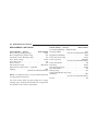
CONTENTS
䡵 Introduction . . . . . . . . . . . . . . . . . . . . . . . . . . . 4
䡵 Vehicle Identification Number
䡵 How To Use This Manual . . . . . . . . . . . . . . . . . . 4
䡵 Vehicle Modifications/Alterations . . . . . . . . . . . . 7
䡵 Warnings And Cautions . . . . . . . . . . . . . . . . . . . 6
.............. 6
4
INTRODUCTION
INTRODUCTION
Congratulations on selecting your new Chrysler LLC
vehicle. Be assured that it represents precision workmanship, distinctive styling, and high quality - all essentials
that are traditional to our vehicles.
This Owner’s Manual has been prepared with the assistance of service and engineering specialists to acquaint
you with the operation and maintenance of your vehicle.
It is supplemented by a Warranty Information Booklet
and various customer-oriented documents. Please take
the time to read these publications carefully. Following
the instructions and recommendations in this manual
will help assure safe and enjoyable operation of your
vehicle.
NOTE: After you read the manual, it should be stored
in the vehicle for convenient referencing and remain
with the vehicle when sold, so that the new owner will
be aware of all safety warnings.
When it comes to service, remember that your authorized
dealer knows your vehicle best, has the factory-trained
technicians and genuine Mopar parts, and cares about
your satisfaction.
HOW TO USE THIS MANUAL
Consult the Table of Contents to determine which section
contains the information you desire.
The detailed Index at the back of this manual contains a
complete listing of all subjects.
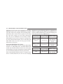
Consult the following table for a description of the
symbols that may be used on your vehicle or throughout
this Owner’s Manual.
INTRODUCTION
5
1
6
INTRODUCTION
WARNINGS AND CAUTIONS
This Owner’s Manual contains WARNINGS against operating procedures that could result in an accident or
bodily injury. It also contains CAUTIONS against procedures that could result in damage to your vehicle. If you
do not read this entire manual, you may miss important
information. Observe all Warnings and Cautions.
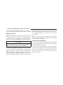
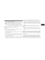
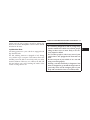
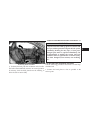
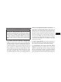
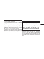
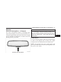
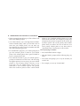
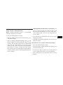
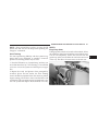
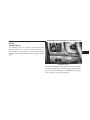
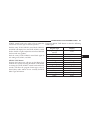
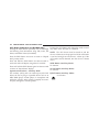
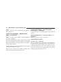
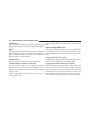
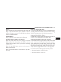
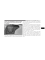
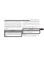
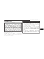
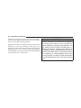
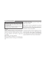
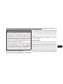
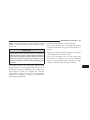
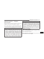
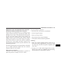
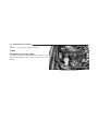
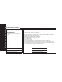
VEHICLE IDENTIFICATION NUMBER
The Vehicle Identification Number (VIN) is on the left
front corner of the instrument panel and is visible from
outside of the vehicle through the windshield. This
number also appears on the Automobile Information
VIN Location
Disclosure Label affixed to a window on your vehicle, the NOTE: It is illegal to remove or alter the VIN.
vehicle registration, and the title.
INTRODUCTION
7
VEHICLE MODIFICATIONS/ALTERATIONS
WARNING!
Any modifications or alterations to this vehicle could
seriously affect its roadworthiness and safety and
may lead to an accident resulting in serious injury or
death.
1
9
THINGS TO KNOW BEFORE STARTING YOUR VEHICLE
2
CONTENTS
䡵 A Word About Your Keys . . . . . . . . . . . . . . . . . 12
䡵 Vehicle Security Alarm . . . . . . . . . . . . . . . . . . . 18
▫ Wireless Ignition Node (WIN) . . . . . . . . . . . . 12
▫ Rearming Of The System . . . . . . . . . . . . . . . . 18
▫ FOB With Integrated Key . . . . . . . . . . . . . . . 13
▫ To Arm The System . . . . . . . . . . . . . . . . . . . 18
▫ Ignition Key Removal . . . . . . . . . . . . . . . . . . 13
▫ To Disarm The System . . . . . . . . . . . . . . . . . 18
▫ Key-In-Ignition Reminder . . . . . . . . . . . . . . . 14
䡵 Illuminated Entry System . . . . . . . . . . . . . . . . . 19
䡵 Sentry Key威 . . . . . . . . . . . . . . . . . . . . . . . . . . 14
䡵 Remote Keyless Entry (RKE)
. . . . . . . . . . . . . . 20
▫ Replacement Keys . . . . . . . . . . . . . . . . . . . . . 16
▫ To Unlock The Doors . . . . . . . . . . . . . . . . . . 20
▫ Customer Key Programming . . . . . . . . . . . . . 16
▫ To Lock The Doors . . . . . . . . . . . . . . . . . . . . 22
▫ General Information . . . . . . . . . . . . . . . . . . . 17
▫ Express Down Window Feature . . . . . . . . . . . 23
10
THINGS TO KNOW BEFORE STARTING YOUR VEHICLE
▫ To Open The Trunk . . . . . . . . . . . . . . . . . . . . 23
䡵 Trunk Lock And Release
▫ Using The Panic Alarm . . . . . . . . . . . . . . . . . 23
䡵 Trunk Safety Warning . . . . . . . . . . . . . . . . . . . 35
▫ Programming Additional Transmitters . . . . . . 24
▫ Trunk Emergency Release . . . . . . . . . . . . . . . 35
▫ Transmitter Battery Service . . . . . . . . . . . . . . 24
䡵 Occupant Restraints . . . . . . . . . . . . . . . . . . . . . 36
▫ General Information . . . . . . . . . . . . . . . . . . . 25
▫ Lap/Shoulder Belts . . . . . . . . . . . . . . . . . . . . 37
䡵 Remote Starting System . . . . . . . . . . . . . . . . . . 26
▫ Lap/Shoulder Belt Untwisting Procedure . . . . 41
▫ How To Use Remote Start . . . . . . . . . . . . . . . 26
▫ Seat Belt Pretensioners . . . . . . . . . . . . . . . . . 42
䡵 Door Locks . . . . . . . . . . . . . . . . . . . . . . . . . . . 28
▫ Enhanced Seat Belt Use Reminder System
(BeltAlert威) . . . . . . . . . . . . . . . . . . . . . . . . . 42
▫ Manual Door Locks . . . . . . . . . . . . . . . . . . . 28
▫ Power Door Locks . . . . . . . . . . . . . . . . . . . . 29
䡵 Windows . . . . . . . . . . . . . . . . . . . . . . . . . . . . 32
▫ Power Windows . . . . . . . . . . . . . . . . . . . . . . 32
▫ Wind Buffeting . . . . . . . . . . . . . . . . . . . . . . . 33
. . . . . . . . . . . . . . . . . 34
▫ Automatic Locking Mode — If Equipped . . . . 44
▫ Seat Belts And Pregnant Women . . . . . . . . . . 44
▫ Seat Belt Extender . . . . . . . . . . . . . . . . . . . . . 45
▫ Driver And Front Passenger Supplemental
Restraint System (SRS) - Airbags . . . . . . . . . . 45
THINGS TO KNOW BEFORE STARTING YOUR VEHICLE
11
▫ Event Data Recorder (EDR) . . . . . . . . . . . . . . 55
▫ Exhaust Gas . . . . . . . . . . . . . . . . . . . . . . . . . 67
▫ Child Restraint . . . . . . . . . . . . . . . . . . . . . . . 57
▫ Safety Checks You Should Make Inside The
Vehicle . . . . . . . . . . . . . . . . . . . . . . . . . . . . . 68
䡵 Engine Break-In Recommendations . . . . . . . . . . 66
䡵 Safety Tips . . . . . . . . . . . . . . . . . . . . . . . . . . . 67
▫ Transporting Passengers . . . . . . . . . . . . . . . . 67
▫ Periodic Safety Checks You Should Make
Outside The Vehicle . . . . . . . . . . . . . . . . . . . 69
2
12
THINGS TO KNOW BEFORE STARTING YOUR VEHICLE
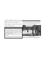
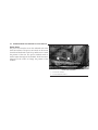
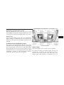
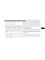
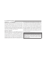
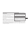
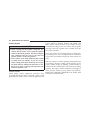
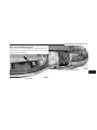
spring-loaded momentary contact position. When reA WORD ABOUT YOUR KEYS
Your vehicle uses a keyless ignition system. This system leased from the START position, the switch automatically
consists of a Fob and a Wireless Ignition Node (WIN) returns to the ON position.
with an integral ignition switch. You can insert the
double-sided integrated key into the ignition switch with
either side up.
Keyless Go Feature
This vehicle may be equipped with the Keyless Go
feature, for more information, refer to “Keyless Go — If
Equipped” under “Starting Procedure” in Section 5 of
this manual.
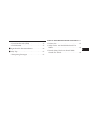
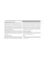
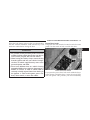
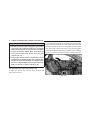
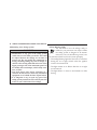
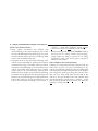
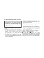
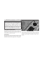
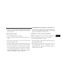
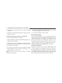
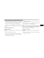
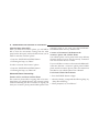
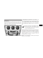
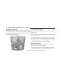
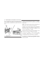
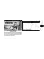
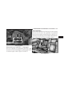
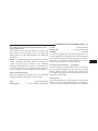
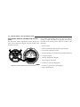
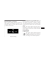
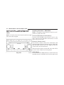
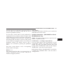
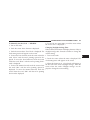
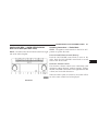
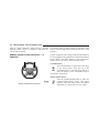
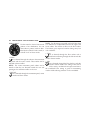
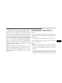
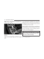
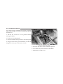
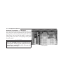
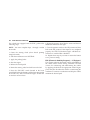
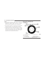
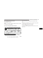
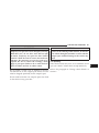
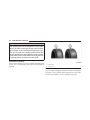
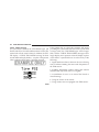
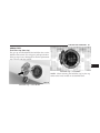
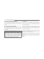
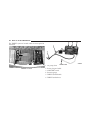
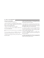
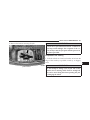
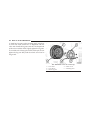
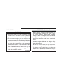
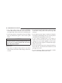
Wireless Ignition Node (WIN)
The Wireless Ignition Node (WIN) operates similar to an
ignition switch. It has four operating positions, three with
detents and one that is spring-loaded. The detent positions are LOCK, ACC, and ON. The START position is a
1
2
3
4
— LOCK
— ACCESSORY
— ON
— START
THINGS TO KNOW BEFORE STARTING YOUR VEHICLE
13
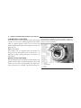
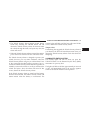
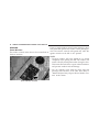
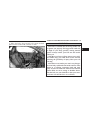
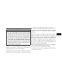
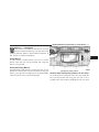
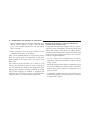
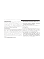
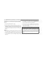
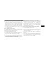
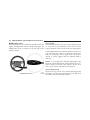
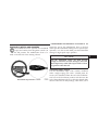
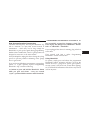
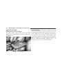
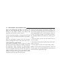
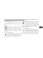
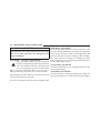
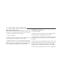
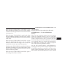
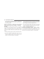
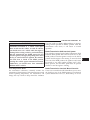
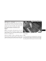
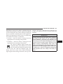
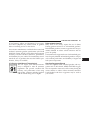
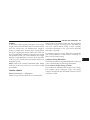
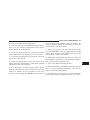
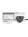
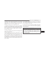
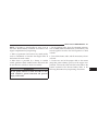
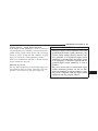
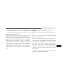
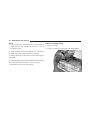
Fob With Integrated Key
The Fob operates the ignition switch. It also contains the
Remote Keyless Entry (RKE) transmitter and an emergency key, which stores in the rear of the Fob.
2
The emergency key allows for entry into the vehicle
should the battery in the vehicle or the Fob go dead. The
emergency key is also for locking the glove box. You can
keep the emergency key with you when valet parking.
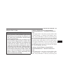
To remove the emergency key from the Fob, slide the
mechanical latch at the top of the Fob sideways with your
thumb and then pull the key out of the Fob with your
other hand.
Emergency Key Removal
NOTE: You can insert the double-sided emergency key
into the lock cylinders with either side up.
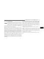
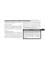
Ignition Key Removal
Place the shift lever in PARK. Turn the key to the LOCK
position and then remove the key.
14
THINGS TO KNOW BEFORE STARTING YOUR VEHICLE
NOTE: The power window switches, radio, power
CAUTION!
sunroof (if equipped), and ignition-powered power outlets will remain active for up to 60 minutes after the An unlocked car is an invitation to thieves. Always
ignition switch is turned to the LOCK position. Opening remove key from the ignition and lock all doors
either door will cancel this feature. The time for this when leaving the vehicle unattended.
feature is programmable. Refer to “Delay Power Off to
Accessories Until Exit,” under “Personal Settings Key-In-Ignition Reminder
(Customer-Programmable Features),” under “Electronic If you open the driver’s door and the key is in the
Vehicle Information Center (EVIC)” in Section 4.
ignition, a chime will sound to remind you to remove the
key.
WARNING!
Never leave children alone in a vehicle. Leaving
unattended children in a vehicle is dangerous for a
number of reasons. A child or others could be seriously or fatally injured. Don’t leave the key in the
ignition. A child could operate power windows,
other controls, or move the vehicle.
NOTE: The Key-In-Ignition reminder only sounds
when the ignition key is placed in the LOCK or ACC
position.
SENTRY KEY姞
The Sentry Key威 Immobilizer System prevents unauthorized vehicle operation by disabling the engine. The
system does not need to be armed or activated. Operation
THINGS TO KNOW BEFORE STARTING YOUR VEHICLE
15
is automatic, regardless of whether the vehicle is locked If the Vehicle Security Light turns on during normal
or unlocked.
vehicle operation (vehicle running for longer than 10 seconds), it indicates that there is a fault in the electronics.
The system uses the factory-mated Remote Keyless Entry
Should this occur, have the vehicle serviced as soon as
(RKE) transmitter with integrated key and Wireless Ignipossible by an authorized dealer.
tion Node (WIN) to prevent unauthorized vehicle operation. Therefore, only RKE transmitters that are pro- NOTE:
grammed to the vehicle can be used to start and operate • The Sentry Key威 Immobilizer System is not compatible with aftermarket remote starting systems. Use of
the vehicle. The system will not allow the engine to crank
these systems may result in vehicle starting problems
if an invalid RKE transmitter is used to operate the
and loss of security protection.
ignition switch.
After turning the ignition switch to the ON position, the • Exxon/Mobil Speedpass™, additional RKE transmitters, or any other transponder-equipped components
Vehicle Security Light will turn on for three seconds for a
on the same key chain will not cause a fault unless the
bulb check. If the light remains on after the bulb check, it
additional part is physically held against the transindicates that there is a problem with the electronics. This
mitter being used to start the vehicle. Cell phones,
condition will result in the engine being shut off after two
pagers, or other RF electronics will not cause interferseconds.
ence with this system.
2
16
THINGS TO KNOW BEFORE STARTING YOUR VEHICLE
All of the RKE transmitters provided with your new Key Programming procedure. This procedure consists of
vehicle have been programmed to the vehicle electronics. programming a blank transmitter to the vehicle electronics. A blank transmitter is one that has never been
Replacement Keys
programmed.
NOTE: Only RKE transmitters that are programmed to
NOTE: When having the Sentry Key威 Immobilizer
the vehicle electronics can be used to start and operate
System serviced, bring all vehicle RKE transmitters with
the vehicle. Once a transmitter is programmed to a
you to the authorized dealer.
vehicle, it cannot be programmed to any other vehicle.
Customer Key Programming
CAUTION!
If you have two valid RKE transmitters with integrated
keys, you can program new transmitters to the system by
Always remove the keys from the vehicle and lock all
performing the following steps:
doors when leaving the vehicle unattended.
1. Insert the first valid integrated key into the ignition
At the time of purchase, the original owner is provided switch and turn the ignition switch to the ON position for
with a four-digit Personal Identification Number (PIN). at least three seconds, but no longer than 15 seconds.
Keep the PIN in a secure location. This number is Turn the ignition switch to the LOCK position and
required for authorized dealer replacement of RKE trans- remove the first key.
mitters. Duplication of RKE transmitters may be performed at an authorized dealer or by using the Customer
THINGS TO KNOW BEFORE STARTING YOUR VEHICLE
17
NOTE: If a programmed key is lost, see your authorized
dealer to have all remaining keys erased from the system’s memory. This will prevent the lost key from
starting your vehicle. The remaining keys must then be
reprogrammed. All vehicle keys must be taken to an
authorized dealer at the time of service to be
3. Insert a blank integrated key into the ignition switch
reprogrammed.
and turn the ignition switch to the ON position within
60 seconds. After 10 seconds, a single chime will sound General Information
and the Vehicle Security Light will stop flashing, turn on The Sentry Key威 system complies with FCC rules Part 15
and with RSS-210 of Industry Canada. Operation is
again for three seconds, and then turn off.
subject to the following conditions:
The new integrated key is programmed. The RKE transmitter will also be programmed during this procedure. • This device may not cause harmful interference.
2. Insert the second valid integrated key and turn the
ignition switch to the ON position within 15 seconds.
After 10 seconds, a chime will sound and the Vehicle
Security Light will begin to flash. Turn the ignition switch
to the LOCK position and remove the second key.
Repeat this procedure to program up to eight keys. If you • This device must accept any interference that may be
received, including interference that may cause undesdo not have a programmed RKE transmitter with inteired operation.
grated key, contact your authorized dealer for details.
2
18
THINGS TO KNOW BEFORE STARTING YOUR VEHICLE
VEHICLE SECURITY ALARM
The Vehicle Security Alarm monitors the vehicle doors
for unauthorized entry and the ignition switch for unauthorized operation. If something triggers the alarm, the
Vehicle Security Alarm will provide the following audible and visible signals: the horn will pulse, the headlights, park lamps and/or turn signals will flash, and the
Vehicle Security Light in the instrument cluster will flash.
Rearming Of The System
If something triggers the alarm, and no action is taken to
disarm it, the Vehicle Security Alarm will turn the horn
off after three minutes, turn all of the visual signals off
after 15 minutes, and then the Vehicle Security Alarm will
rearm itself.
Keyless Entry (RKE) transmitter. After the last door is
closed, or if both doors are closed, the Vehicle Security
Alarm will arm itself in about 16 seconds. During that
time, the Vehicle Security Light will flash. If it does not
illuminate, the Vehicle Security Alarm is not arming. In
addition, if you open a door during the arming period,
the Vehicle Security Alarm will cancel the arming process. If you wish to rearm the Vehicle Security Alarm after
closing the door, you must repeat one of the previouslydescribed arming sequences.
To Disarm The System
Either press the UNLOCK button on the RKE transmitter
or insert a valid ignition key into the ignition switch and
turn the key to the ON position.
To Arm The System
NOTE:
Remove the key from the ignition switch and either press • The driver’s door key cylinder and the trunk button on
a power door LOCK switch while the driver or passenger
the RKE transmitter cannot arm or disarm the Vehicle
door is open or press the LOCK button on the Remote
Security Alarm.
THINGS TO KNOW BEFORE STARTING YOUR VEHICLE
19
• The Vehicle Security Alarm remains armed during
trunk entry. Pressing the TRUNK button will not
disarm the Vehicle Security Alarm. If someone enters
the vehicle through the trunk, and opens any door, the
alarm will sound.
exterior lights will flash, and the horn will sound. If this
occurs, disarm the Vehicle Security Alarm.
The Vehicle Security Alarm is designed to protect your
vehicle; however, you can create conditions where the
Vehicle Security Alarm will give you a false alarm. If one
of the previously-described arming sequences has occurred, the Vehicle Security Alarm will arm regardless of
whether you are in the vehicle or not. If you remain in the
vehicle and open a door, the alarm will sound. If this
occurs, disarm the Vehicle Security Alarm.
ILLUMINATED ENTRY SYSTEM
The courtesy lights will turn on when you press the
UNLOCK button on the Remote Keyless Entry (RKE)
transmitter or open any door.
Tamper Alert
If something has triggered the Vehicle Security Alarm in
your absence, the horn will sound three times when you
• When the Vehicle Security Alarm is armed, the interior disarm the Vehicle Security Alarm. Check the vehicle for
power door lock switches will not unlock the doors. tampering.
If the Vehicle Security Alarm is armed and the battery
becomes disconnected, the Vehicle Security Alarm will
remain armed when the battery is reconnected. The
The lights will fade to off after approximately 30 seconds
or they will immediately fade to off once the ignition
switch is turned ON from the LOCK position.
2
20
THINGS TO KNOW BEFORE STARTING YOUR VEHICLE
NOTE:
• None of the courtesy lights will operate if the dimmer
control is in the “defeat” position (extreme downward
position), unless the overhead map/reading lights are
turned on manually.
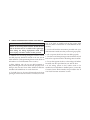
REMOTE KEYLESS ENTRY (RKE)
The Remote Keyless Entry (RKE) allows you to lock or
unlock the doors, open the trunk, or activate the Panic
Alarm from distances up to approximately 66 ft (20 m)
using a hand-held radio transmitter. The transmitter does
not need to be pointed at the vehicle to activate the
system.
NOTE: Inserting the Fob with Integrated Key into the
ignition switch disables all buttons on that transmitter;
however, the buttons on the remaining transmitters will
continue to work. Driving at speeds 5 mph (8 km/h) and
above disables all transmitter buttons for all fobs.
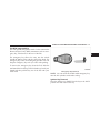
RKE Transmitter
To Unlock The Doors
Press and release the UNLOCK button on the transmitter
once to unlock the driver’s door or twice within five
seconds, to unlock both doors. The turn signal lights will
flash to acknowledge the unlock signal. The illuminated
entry system will also turn on.
THINGS TO KNOW BEFORE STARTING YOUR VEHICLE
Remote Key Unlock, Driver Door/All Doors First
This feature lets you program the system to unlock either
the driver’s door or both doors on the first press of the
UNLOCK button on the transmitter. Refer to “Remote
Key Unlock,” under “Personal Settings (CustomerProgrammable Features),” under “Electronic Vehicle Information Center (EVIC)” in Section 4.
21
4. Repeat these steps if you want to return this feature to
its previous setting.
NOTE: Pressing the LOCK button on the transmitter
while you are inside the vehicle will activate the Security
Alarm. Opening a door with the Security Alarm activated
will cause the alarm to sound. Press the UNLOCK button
to deactivate the Security Alarm.
• When not using the EVIC, perform the following
Flash Lights with Remote Key Lock
steps:
This feature will cause the turn signal lights to flash when
1. Press and hold the LOCK button on a programmed the doors are locked or unlocked with the transmitter.
transmitter for at least 4 seconds, but no longer than This feature can be turned on or turned off. Refer to
10 seconds. Then, press and hold the UNLOCK button “Flash Lights with Remote Key Lock,” under ⬙Personal
while still holding the LOCK button.
Settings (Customer-Programmable Features),” under
“Electronic Vehicle Information Center (EVIC)” in Sec2. Release both buttons at the same time.
tion 4.
3. Test the feature while outside of the vehicle by pressing the LOCK/UNLOCK buttons on the transmitter with
the ignition switch in the LOCK position and the key
removed.
2
22
THINGS TO KNOW BEFORE STARTING YOUR VEHICLE
• When not using the EVIC, perform the following Alarm. Opening a door with the Security Alarm activated
steps:
will cause the alarm to sound. Press the UNLOCK button
to deactivate the Security Alarm.
1. Press and hold the UNLOCK button on a programmed
transmitter for at least 4 seconds, but no longer than Turn Headlights On with Remote Key Unlock
10 seconds. Then, press and hold the LOCK button while This feature activates the headlights for up to 90 seconds
when the doors are unlocked with the transmitter. The
still holding the UNLOCK button.
time for this feature is programmable. Refer to “Turn
2. Release both buttons at the same time.
Headlights On with Remote Key Unlock,” under “Per3. Test the feature while outside of the vehicle by press- sonal Settings (Customer-Programmable Features),” uning the LOCK/UNLOCK buttons on the transmitter with der “Electronic Vehicle Information Center (EVIC)” in
the ignition switch in the LOCK position and the key Section 4.
removed.
To Lock The Doors
4. Repeat these steps if you want to return this feature to Press and release the LOCK button on the transmitter to
lock both doors. The turn signal lights will flash and the
its previous setting.
horn will chirp to acknowledge the signal.
NOTE: Pressing the LOCK button on the transmitter
while you are in the vehicle will activate the Security Sound Horn with Remote Key Lock
This feature will cause the horn to chirp when the doors
are locked with the transmitter. This feature can be
THINGS TO KNOW BEFORE STARTING YOUR VEHICLE
turned on or turned off. Refer to “Sound Horn with
Remote Key Lock,” under “Personal Settings (CustomerProgrammable Features),” under “Electronic Vehicle Information Center (EVIC)” in Section 4.
23
NOTE: Pressing the LOCK button on the transmitter
while you are in the vehicle will activate the Security
Alarm. Opening a door with the Security Alarm activated
will cause the alarm to sound. Press the UNLOCK button
to deactivate the Security Alarm.
• When not using the EVIC, perform the following
steps:
Express Down Window Feature
This feature allows you to remotely lower both door
1. Press the LOCK button on a programmed transmitter
windows at the same time. To use this feature, press and
for at least 4 seconds, but no longer than 10 seconds.
release the UNLOCK button on the transmitter and then
Then, press the PANIC button while still holding the
immediately press and hold the UNLOCK button until
LOCK button.
the windows lower to the level desired or until they
lower completely.
2. Release both buttons at the same time.
3. Test the feature while outside of the vehicle by press- To Open The Trunk
ing the LOCK button on the transmitter with the ignition Press the TRUNK button on the transmitter two times
within five seconds to open the trunk.
switch in the LOCK position and the key removed.
4. Repeat these steps if you want to return this feature to Using The Panic Alarm
To turn the Panic Alarm feature ON or OFF, press and
its previous setting.
hold the PANIC button on the transmitter for at least one
2
24
THINGS TO KNOW BEFORE STARTING YOUR VEHICLE
second and release. When the Panic Alarm is on, the Programming Additional Transmitters
headlights and park lights will flash, the horn will pulse If you do not have a programmed RKE transmitter,
contact your authorized dealer for details.
on and off, and the interior lights will turn on.
The Panic Alarm will stay on for three minutes unless Transmitter Battery Service
you turn it off by either pressing the PANIC button a The recommended replacement battery is CR2032.
second time or drive the vehicle at a speed of 5 mph
NOTE: Perchlorate Material – special handling may
(24 km/h) or greater.
apply.
See
www.dtsc.ca.gov/hazardouswaste/
perchlorate.
NOTE:
• The interior lights will turn off if you turn the ignition
1. If the RKE transmitter is equipped with a screw,
switch to the ACC or ON position while the Panic
remove the screw. With the RKE ransmitter buttons
Alarm is activated. However, the exterior lights and
facing down, use a flat blade to pry the two halves of the
horn will remain on.
RKE transmitter apart. Make sure not to damage the
• You may need to be less than 35 ft (11 m) from the elastomer seal during removal.
vehicle when using the transmitter to turn off the
2. Remove and replace the battery. When replacing the
Panic Alarm due to the radio frequency noises emitted
battery, match the + sign on the battery to the + sign on
by the system.
the inside of the battery clip, located on the back cover.
THINGS TO KNOW BEFORE STARTING YOUR VEHICLE
25
Avoid touching the new battery with your fingers. Skin NOTE: Changes or modifications not expressly apoils may cause battery deterioration. If you touch a proved by the party responsible for compliance could
void the user’s authority to operate the equipment.
battery, clean it with rubbing alcohol.
3. To reassemble the RKE transmitter case, snap the two
halves of the case together. Make sure there is an even
“gap” between the two halves. If equipped, install and
tighten the screw until snug. Test RKE transmitter
operation.
If your RKE transmitter fails to operate from a normal
distance, check for these two conditions:
1. A weak battery in the transmitter. The expected life of
the battery is a minimum of three years.
2. Closeness to a radio transmitter such as a radio station
General Information
tower, airport transmitter, and some mobile or CB radios.
This device complies with Part 15 of the FCC rules and
RSS 210 of Industry Canada. Operation is subject to the
following conditions:
• This device may not cause harmful interference.
• This device must accept any interference received,
including interference that may cause undesired
operation.
2
26
THINGS TO KNOW BEFORE STARTING YOUR VEHICLE
REMOTE STARTING SYSTEM
• Ignition key removed from ignition switch
This system uses the Remote Keyless Entry
• Battery at an acceptable charge level, and
(RKE) transmitter to start the engine conveniently from outside the vehicle while still • RKE PANIC button not pressed.
maintaining security. The system has a range of
WARNING!
328 ft (100 m).
NOTE: The vehicle must be equipped with an automatic transmission to be equipped with Remote Start.
How To Use Remote Start
All of the following conditions must be met before the
engine will remote start:
• Shift lever in PARK
• Doors closed
• Hood closed
• Hazard switch off
• Brake switch inactive (brake pedal not pressed)
• Do not start or run an engine in a closed garage or
confined area. Exhaust gas contains Carbon Monoxide (CO) which is odorless and colorless. Carbon monoxide is poisonous and can cause serious
injury or death when inhaled.
• Keep Remote Keyless Entry (RKE) transmitters
away from children. Operation of the Remote Start
System, windows, door locks or other controls
could cause serious injury or death.
THINGS TO KNOW BEFORE STARTING YOUR VEHICLE
27
cycled by pushing the START/STOP button twice (or
To Enter Remote Start Mode
the ignition switch must be cycled to the ON position)
Press and release the REMOTE START button
before you can repeat the start sequence for a third
on the RKE transmitter twice, within five seccycle.
onds. The parking lights will flash and the horn
will chirp twice (if programmed). Then, the
To Exit Remote Start Mode without Driving the
engine will start and the vehicle will remain in the
Vehicle
Remote Start mode for a 15-minute cycle.
• Press and release the REMOTE START button one time
NOTE:
or allow the engine to run for the entire 15-minute
• If an engine fault is present the vehicle will start and
cycle.
then shut down 10 seconds later.
NOTE: To avoid unintentional shut downs, the system
• The park lamps will turn on and remain on during
will disable the one time press of the REMOTE START
Remote Start mode.
button for two seconds after receiving a valid Remote
• For security, power window and power sunroof op- Start request.
eration (if equipped) are disabled when the vehicle is
To Exit Remote Start Mode and Drive the Vehicle
in the Remote Start mode.
Before the end of 15 minute cycle, press and release the
• The engine can be started two consecutive times with UNLOCK button on the RKE transmitter to unlock the
the RKE transmitter. However, the ignition must be doors and disarm the Vehicle Security Alarm (if
2
28
THINGS TO KNOW BEFORE STARTING YOUR VEHICLE
equipped). Then, prior to the end of the 15 minute cycle,
press and release the START/STOP button. If the
START/STOP button is not present, insert the key into
the ignition switch and turn the switch to the ON
position.
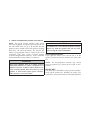
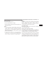
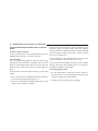
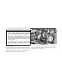
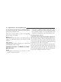
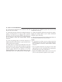
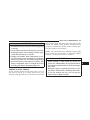
DOOR LOCKS
Manual Door Locks
To lock each door, push the door lock plunger on each
door trim panel downward. To unlock each door, pull the
door lock plunger on each door trim panel upward.
NOTE:
• For vehicles not equipped with Keyless Go feature, the
ignition switch must be in the ON position in order to
drive the vehicle.
• For vehicles not equipped with Keyless Go feature, the
message “Insert Key/Turn To On” will display in the
EVIC until you insert the key. Once inserted, the
message “Turn To On” will display in the EVIC until
you turn the key to ON.
• For vehicles equipped with Keyless Go feature, the
message “Push Button/Insert Key” will display in the
EVIC until you push the START button.
Door Lock Plunger
THINGS TO KNOW BEFORE STARTING YOUR VEHICLE
29
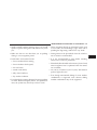
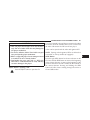
If the door lock plunger is down when you shut the door, Power Door Locks
the door will lock. Therefore, make sure the key is not The power door lock switch is located on each door trim
panel. Use this switch to lock or unlock the doors.
inside the vehicle before closing the door.
2
WARNING!
• For personal security and safety in the event of an
accident, lock the vehicle doors before you drive as
well as when you park and leave the vehicle.
• When leaving the vehicle, always remove the key
from the ignition and lock your vehicle. Unsupervised use of vehicle equipment may cause severe
personal injuries and death.
• Never leave children alone in a vehicle. Leaving
unattended children in a vehicle is dangerous for a
number of reasons. A child or others could be
seriously or fatally injured. Don’t leave the key in
the ignition. A child could operate power windows, other controls, or move the vehicle.
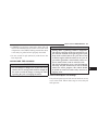
Power Door Lock Switch
If you press the power door lock switch while the key is
in the ignition, and either door is open, the power locks
will not operate. This prevents you from accidentally
30
THINGS TO KNOW BEFORE STARTING YOUR VEHICLE
locking the key in the vehicle. Removing the key or
closing the door will allow the locks to operate. If a door
is open, the key is in the ignition, and the ignition is in the
LOCK or ACC position, a chime will sound as a reminder
to remove the key.
Automatic Door Locks — If Equipped
The auto door lock feature can be enabled or disabled by
your authorized dealer. See your authorized dealer for
programming.
3. All doors are closed
3. The transmission is in NEUTRAL or PARK
4. The throttle is pressed
4. The driver door is opened
5. The vehicle speed is above 15 mph (24 km/h), and
5. The doors were not previously unlocked, and
Automatic Unlock Doors on Exit
Automatic Door Locks
The doors will unlock automatically if:
The doors will lock automatically if all of the following
1. The Automatic Unlock Doors On Exit feature is enconditions are met:
abled
1. The Automatic Door Locks feature is enabled
2. The transmission was in gear and the vehicle speed
2. The transmission is in gear
returned to 0 mph (0 km/h)
6. The doors were not previously locked using the power 6. The vehicle speed is 0 mph (0 km/h).
door lock switch or Remote Keyless Entry (RKE)
transmitter.
THINGS TO KNOW BEFORE STARTING YOUR VEHICLE
Automatic Unlock Doors on Exit Programming
The Automatic Unlock Doors On Exit feature can be
enabled or disabled. Refer to “Unlock Doors Automatically on Exit,” under “Personal Settings (CustomerProgrammable Features),” under “Electronic Vehicle Information Center (EVIC)” in Section 4.
31
4. Within 30 seconds, depress the power door UNLOCK
switch to unlock the doors.
5. A single chime will indicate the completion of the
programming.
NOTE: If you do not hear the chime, it means that the
system did not enter the programming mode and you
• When not using the EVIC, perform the following
will need to repeat the procedure.
steps:
6. Repeat these steps if you want to return this feature to
1. Enter the vehicle and close all doors.
its previous setting.
2. Place the key in the ignition switch.
NOTE: Use the Automatic Unlock Doors On Exit feature
3. Within 15 seconds, cycle the ignition switch between in accordance with local laws.
LOCK and ON and then back to LOCK four times ending
up in the LOCK position. However, do not start the
engine.
2
32
THINGS TO KNOW BEFORE STARTING YOUR VEHICLE
There is a single window control on the passenger’s door
trim panel that operates the window on the passenger’s
Power Windows
door. The window controls will operate only when the
The window controls on the driver’s door control both of
ignition switch is in the ON or ACC position.
the door windows.
NOTE:
• The door window will lower slightly if it is closed
completely when opening the door. The window will
return to its fully closed position after closing the door.
This action allows the door to open without resistance
and prevents window and seal damage.
WINDOWS
• You can remotely lower both the driver side and
passenger side windows at the same time. Refer to
“Remote Keyless Entry/Express Down Window Feature” in this section.
Power Window Switches
THINGS TO KNOW BEFORE STARTING YOUR VEHICLE
WARNING!
Never leave children in a vehicle with the key in the
ignition switch. Occupants, particularly unattended
children, can become entrapped by the windows
while operating the power window switches. Such
entrapment may result in serious injury or death.
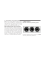
AUTO-Down Feature
The driver’s door power window switch and passenger
door power window switch have an AUTO-down feature. Press the window switch to the second detent,
release, and the window will go down automatically.
To open the window part way, press the window switch
to the first detent and release it when you want the
window to stop.
To stop the window from going all the way down during
the AUTO-down operation, pull up on the switch briefly.
33
The power window switches will remain active for up to
60 minutes after the ignition switch is turned OFF.
Opening either door will cancel this feature. The time for
this feature is programmable. Refer to “Delay Power Off
to Accessories Until Exit,” under “Personal Settings
(Customer-Programmable Features)” in the “Electronic
Vehicle Information Center (EVIC),” in Section 4 of this
manual.
Wind Buffeting
Wind buffeting can be described as the perception of
pressure on the ears or a helicopter-type sound in the
ears. Your vehicle may exhibit wind buffeting with the
windows down, or the sunroof (if equipped) in certain
open or partially open positions. This is a normal occurrence and can be minimized. If the buffeting occurs with
one window open, then open the other window to
minimize the buffeting. If the buffeting occurs with the
sunroof open, then adjust the sunroof opening to minimize the buffeting.
2
34
THINGS TO KNOW BEFORE STARTING YOUR VEHICLE
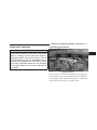
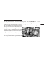
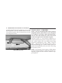
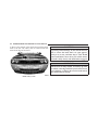
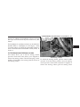
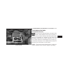
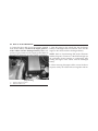
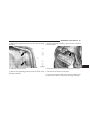
TRUNK LOCK AND RELEASE
The trunk lid can be released from inside the vehicle by
pressing the Trunk Release button. The button is located
on the instrument panel to the left of the steering wheel.
With the ignition switch in the ON position, the Trunk
Open symbol will display in the instrument cluster
indicating that the trunk is open. The odometer display
will reappear once the trunk is closed.
NOTE: The transmission must be in PARK before the With the ignition switch in the LOCK position or the key
button will operate. If equipped with a manual transmis- removed from the ignition switch, the Trunk Open symsion, the vehicle speed must be under 5 mph (8 km/h) bol will display until the trunk is closed.
before the button will operate.
The trunk lid can be released from
outside the vehicle by pressing the
Trunk Release button on the Remote Keyless Entry (RKE) transmitter twice within five seconds.
Trunk Release
Button
THINGS TO KNOW BEFORE STARTING YOUR VEHICLE
TRUNK SAFETY WARNING
35
Trunk Emergency Release
WARNING!
2
Do not allow children to have access to the trunk,
either by climbing into the trunk from outside, or
through the inside of the vehicle. Always close the
trunk lid when your vehicle is unattended. Once in
the trunk, young children may not be able to escape,
even if they entered through the rear seat. If trapped
in the trunk, children can die from suffocation or
heat stroke.
Emergency Release
The trunk of your vehicle is equipped with an emergency
release handle. It is located on the inside of the trunk lid,
near the latch, and is coated so that it glows in a darkened
trunk. Pull on the handle to open the trunk.
36
THINGS TO KNOW BEFORE STARTING YOUR VEHICLE
OCCUPANT RESTRAINTS
WARNING!
Some of the most important safety features in your
vehicle are the restraint systems. These include the front In a collision, you and your passengers can suffer
and rear seat belts for the driver and all passengers, the much greater injuries if you are not properly buckled
front airbags for both the driver and front passenger, and up. You can strike the interior of your vehicle or other
the supplemental side curtain airbags for the driver and passengers or you can be thrown out of the vehicle.
passengers seated next to a window. If you will be Always be sure you and others in your vehicle are
carrying children too small for adult-sized belts, your buckled up properly.
seat belts also can be used to hold infant and child
restraint systems.
Buckle up even though you are an excellent driver, even
on short trips. Someone on the road may be a poor driver
Please pay close attention to the information in this
and cause a collision that includes you. This can happen
section. It tells you how to use your restraint system
far away from home or on your own street.
properly, to keep you and your passengers as safe as
possible.
Research has shown that seat belts save lives, and they
can reduce the seriousness of injuries in a collision. Some
of the worst injuries happen when people are thrown
from the vehicle. Seat belts reduce the possibility of
THINGS TO KNOW BEFORE STARTING YOUR VEHICLE
ejection and the risk of injury caused by striking the
inside of the vehicle. Everyone in a motor vehicle should
be belted at all times.
Lap/Shoulder Belts
All seating positions in your vehicle are equipped with
lap/shoulder belts.
The belt webbing retractor is designed to lock during
very sudden stops or impacts. This feature allows the
shoulder part of the belt to move freely with you under
normal conditions. However, in a collision, the belt will
lock and reduce your risk of striking the inside of the
vehicle or being thrown out.
37
WARNING!
• It is extremely dangerous to ride in a cargo area,
inside or outside of a vehicle. In a collision, people
riding in these areas are more likely to be seriously injured or killed.
• Do not allow people to ride in any area of your
vehicle that is not equipped with seats and seat
belts.
• Be sure everyone in your vehicle is in a seat and
using a seat belt properly.
• Wearing a seat belt incorrectly is dangerous. Seat
belts are designed to go around the large bones of
your body. These are the strongest parts of your
body and can take the forces of a collision best.
(Continued)
2
38
THINGS TO KNOW BEFORE STARTING YOUR VEHICLE
WARNING! (Continued)
• Wearing your belt in the wrong place could make
your injuries in a collision much worse. You might
suffer internal injuries, or you could even slide out
of part of the belt. Follow these instructions to
wear your seat belt safely and to keep your passengers safe, too.
• Two people should never be belted into a single
seat belt. People belted together can crash into one
another in an accident, hurting one another badly.
Never use a lap/shoulder belt or a lap belt for more
than one person, no matter what their size.
2. The seat belt latch plate is contacting the seat when the
belt is routed through the seat web guide. When the belt
is routed outside of the seat web guide, the latch plate
will contact the quarter trim panel. Grasp the latch plate
and pull out the belt. Slide the latch plate up the webbing
as far as necessary to make the belt go around your lap.
Lap/Shoulder Belt Operating Instructions
1. Enter the vehicle and close the door. Sit back and
adjust the front seat.
Latch Plate
THINGS TO KNOW BEFORE STARTING YOUR VEHICLE
3. When the belt is long enough to fit, insert the latch
plate into the buckle until you hear a “click.”
Latch Plate To Buckle
39
WARNING!
• A belt that is buckled into the wrong buckle will
not protect you properly. The lap portion could ride
too high on your body, possibly causing internal
injuries. Always buckle your belt into the buckle
nearest you.
• A belt that is too loose will not protect you as well.
In a sudden stop, you could move too far forward,
increasing the possibility of injury. Wear your seat
belt snug.
• A belt that is worn under your arm is very dangerous. Your body could strike the inside surfaces of the
vehicle in a collision, increasing head and neck
injury. A belt worn under the arm can cause internal
injuries. Ribs are not as strong as shoulder bones.
Wear the belt over your shoulder so that your strongest bones will take the force in a collision.
(Continued)
2
40
THINGS TO KNOW BEFORE STARTING YOUR VEHICLE
WARNING! (Continued)
WARNING!
• A shoulder belt placed behind you will not protect
you from injury during a collision. You are more
likely to hit your head in a collision if you do not
wear your shoulder belt. The lap and shoulder belt
are meant to be used together.
• A lap belt worn too high can increase the risk of
internal injury in a collision. The belt forces won’t be
at the strong hip and pelvic bones, but across your
abdomen. Always wear the lap belt as low as possible and keep it snug.
• A twisted belt cannot do its job as well. In a
collision, it could even cut into you. Be sure the belt
is straight. If you cannot straighten a belt in your
vehicle, take it to your authorized dealer and have it
fixed.
4. Position the lap belt across your thighs, below your
abdomen. To remove slack in the lap belt portion, pull up
a bit on the shoulder belt. To loosen the lap belt if it is too
tight, tilt the latch plate and pull on the lap belt. A snug
belt reduces the risk of sliding under the belt in a
collision.
5. Position the shoulder belt on your chest so that it is
comfortable and not resting on your neck. The retractor
will withdraw any slack in the belt.
THINGS TO KNOW BEFORE STARTING YOUR VEHICLE
41
WARNING!
A frayed or torn belt could rip apart in a collision and
leave you with no protection. Inspect the belt system
periodically, checking for cuts, frays, or loose parts.
Damaged parts must be replaced immediately. Do
not disassemble or modify the system. Seat belt
assemblies must be replaced after a collision if they
have been damaged (bent retractor, torn webbing,
etc.).
Lap/Shoulder Belt Untwisting Procedure
Use the following procedure to untwist a twisted lap/
6. To release the belt, push the red button on the buckle. shoulder belt.
The belt will automatically retract to its stowed position.
1. Position the latch plate as close as possible to the
If necessary, slide the latch plate down the webbing to
anchor point.
allow the belt to retract fully.
Removing Slack From Belt
2
42
THINGS TO KNOW BEFORE STARTING YOUR VEHICLE
2. At about 6 to 12 in (15 to 30 cm) above the latch plate, NOTE: These devices are not a substitute for proper seat
grasp and twist the belt webbing 180 degrees to create a belt placement by the occupant. The seat belt still must be
worn snug and positioned properly.
fold that begins immediately above the latch plate.
3. Slide the latch plate upward over the folded webbing. The pretensioners are triggered by the Occupant ReThe folded webbing must enter the slot at the top of the straint Controller (ORC). (Refer to information on Airbags in this section). Like the front airbags, the pretenlatch plate.
sioners are single use items. After a collision that is severe
4. Continue to slide the latch plate up until it clears the
enough to deploy the airbags and pretensioners, both
folded webbing.
must be replaced.
Seat Belt Pretensioners
Enhanced Seat Belt Use Reminder System
The seat belts for both front seating positions are
(BeltAlert姞)
equipped with pretensioning devices that are designed to
If the driver’s seat belt has not been buckled within
remove any slack from the seat belts in the event of a
60 seconds of starting the vehicle and if the vehicle speed
collision. These devices improve the performance of the
is greater than 5 mph (8 km/h), the Enhanced Seat Belt
seat belt system by assuring that the belt is tight around
Use Reminder System (BeltAlert威) will alert the driver to
the occupant in a collision. Pretensioners work for all size
buckle the seat belt. The driver should also instruct all
occupants, including those in child restraints.
other occupants to buckle their seat belts. Once the
warning is triggered, the BeltAlert威 will continue to
THINGS TO KNOW BEFORE STARTING YOUR VEHICLE
chime and flash the Seat Belt Reminder Light for 96 seconds or until the driver’s seat belt is buckled. The
BeltAlert威 will be reactivated if the driver’s seat belt is
unbuckled for more than 10 seconds and the vehicle
speed is greater than 5 mph (8 km/h).
43
NOTE: You must perform the following steps within
60 seconds of turning the ignition switch to the ON
position.
3. Within 60 seconds of turning the ignition switch to the
ON position, unbuckle and then re-buckle the driver’s
seat belt at least three times, ending with the seat belt
BeltAlert威 Programming
The BeltAlert威 can be enabled or disabled by your buckled.
authorized dealer or by performing the following steps:
NOTE: Watch for the Seat Belt Reminder Light to turn
NOTE: Chrysler LLC does not recommend deactivating on while unbuckling the seat belt and turn off while
the BeltAlert威.
re-buckling the seat belt. It may be necessary to retract
the seat belt.
1. With both doors closed, and the ignition switch in any
position except ON or START, buckle the driver’s seat 4. Turn the ignition switch to the LOCK position. A
belt.
single chime will sound to signify that you have successfully completed the programming.
2. Turn the ignition switch to the ON position, but do not
start the engine. Wait for the Seat Belt Reminder Light to The BeltAlert威 can be reactivated by repeating this proturn off and then proceed to the next step.
cedure.
2
44
THINGS TO KNOW BEFORE STARTING YOUR VEHICLE
NOTE: When the BeltAlert威 is deactivated, the Seat Belt 3. Allow the belt to retract. As the belt retracts, you will
Reminder Light will continue to illuminate as long as the here a clicking sound. This indicates the safety belt is
now in the Automatic Locking Mode.
driver’s seat belt is unbuckled.
Automatic Locking Mode — If Equipped
In this mode, the shoulder belt is automatically prelocked. However, the belt will still retract to remove slack
in the shoulder belt. Use the Automatic Locking Mode
any time a child safety seat is installed in a seating
position that has a seat belt with this feature. Children
12 years old and younger should be properly restrained
in the rear seat whenever possible.
How to Engage the Automatic Locking Mode
1. Buckle the combination lap and shoulder belt.
How to Disengage the Automatic Locking Mode
Unbuckle the combination lap and shoulder belt and
allow it to retract completely to disengage the Automatic
Locking Mode and activate the vehicle sensitive (emergency) locking mode.
Seat Belts and Pregnant Women
We recommend that pregnant women use the seat belts
throughout their pregnancy. Keeping the mother safe is
the best way to keep the baby safe.
Pregnant women should wear the lap part of the belt
across the thighs and as snug across the hips as possible.
2. Grasp the shoulder portion and pull downward until
Keep the belt low so that it does not come across the
the entire belt is extracted.
abdomen. That way the strong bones of the hips will take
the force if there is a collision.
THINGS TO KNOW BEFORE STARTING YOUR VEHICLE
Seat Belt Extender
If a seat belt is too short even when fully extended your
authorized dealer can provide you with a seat belt
extender. This extender should be used only if the
existing belt is not long enough. When it is not required,
remove the extender and store it.
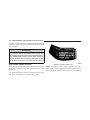
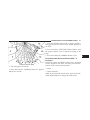
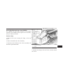
systems. The driver side front airbag is mounted in the
center of the steering wheel. The passenger side front
airbag is mounted in the instrument panel, above the
glove compartment. The words SRS AIRBAG are embossed on the airbag covers.
WARNING!
Using a seat belt extender when not needed can
increase the risk of injury in a collision. Only use
when the seat belt is not long enough when it is worn
low and snug and in the recommended seating position. Remove and store the extender when not
needed.
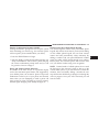
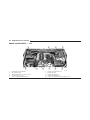
Driver and Front Passenger Supplemental
Restraint System (SRS) - Airbags
This vehicle has front airbags for both the driver and
front passenger as a supplement to the seat belt restraint
45
1 — Airbags
2 — Knee Bolsters
2
46
THINGS TO KNOW BEFORE STARTING YOUR VEHICLE
NOTE: The front airbags are certified to the Federal This vehicle is also equipped with supplemental side
regulations that allow less forceful deployment.
curtain airbags (located above the side windows) to
protect the driver and passenger sitting next to a window.
The front airbags have a multistage inflator design. This
Their covers are also labeled SRS AIRBAG.
allows the airbag to have different rates of inflation that
are based on collision severity.
WARNING!
• Do not put anything on or around the front airbag
covers or attempt to open them. You may damage the
airbags and you could be injured because the airbags
are no longer functional. These protective covers for
the airbag cushions are designed to open only when
the airbags are inflating.
• Do not drill, cut or tamper with the knee bolster in
any way.
• Do not mount any accessories to the knee bolster
such as alarm lights, stereos, citizens band radios etc.
Side Window Airbag
NOTE: Airbag covers may not be obvious in the interior
trim, but they will open to allow airbag deployment.
THINGS TO KNOW BEFORE STARTING YOUR VEHICLE
WARNING!
• Do not stack luggage or other cargo up high
enough to block the location of the side curtain
airbag. The area where the side curtain airbag is
located should remain free from any obstructions.
• Do not have any accessory items installed which
will alter the roof, including adding a sunroof to
your vehicle. Do not add roof racks that require
permanent attachments (bolts or screws) for installation on the vehicle roof. Do not drill into the roof
of the vehicle for any reason.
47
protection for the driver and front passenger. Side curtain
airbags also work with seat belts to improve occupant
protection.
While the seat belts are designed to protect you in many
types of collisions, the front airbags will deploy in
moderate-to-severe frontal collisions. The supplemental
side curtain airbag on the crash side of the vehicle will
also trigger in moderate-to-severe side collisions. However, even in collisions where the airbags deploy, you
need the seat belts to keep you in the correct position for
the airbags to protect you properly.
Here are some simple steps you can take to minimize
NOTE: Do not use a clothing bar mounted to the coat the risk of harm from a deploying airbag:
hooks in this vehicle. A clothing bar will impede the 1. Children 12 years old and younger should ride buckproper performance of the curtain airbags.
led up in the rear seat.
Along with the seat belts, front airbags work with the
instrument panel knee bolsters to provide improved
2
48
THINGS TO KNOW BEFORE STARTING YOUR VEHICLE
WARNING!
Infants in rear-facing child restraints should NEVER
ride in the front seat of a vehicle with a passenger
front airbag. An airbag deployment could cause
severe injury or death to infants in that position.
seat as far back as possible and use the proper child
restraint. (Refer to information on Child Restraint in this
section.)
5. You should read the instructions provided with your
child restraint to make sure that you are using it properly.
6. All occupants should use their seat belts properly.
2. Children who are not big enough to wear the vehicle
7. The driver and front passenger seats should be moved
seat belt properly should be secured in the rear seat in
back as far as practical to allow the airbags time to inflate.
child restraints or belt-positioning booster seats. (Refer to
8. Do not lean against the door, as the airbags will inflate
information on Child Restraint in this section.)
forcefully into the space between you and the door.
3. Older children who do not use child restraints or
belt-positioning booster seats should ride properly buck- 9. If the airbag system in this vehicle needs to be
led up in the rear seat. Never allow children to slide the modified to accommodate a disabled person, contact the
Customer Center. Phone numbers are provided in the ⬙If
shoulder belt behind them or under their arm.
You Need Customer Assistance⬙ section.
4. If a child from 1 to 12 years old must ride in the front
passenger seat because the vehicle is crowded, move the
THINGS TO KNOW BEFORE STARTING YOUR VEHICLE
WARNING!
• Relying on the airbags alone could lead to more
severe injuries in a collision. The airbags work
with your seat belt to restrain you properly. In
some collisions, the airbags won’t deploy at all.
Always wear your seat belts even though you have
airbags.
• Being too close to the steering wheel or instrument
panel during airbag deployment could cause serious injury. Airbags need room to inflate. Sit back,
comfortably extending your arms to reach the
steering wheel or instrument panel.
• This vehicle has supplemental side curtain airbags, and they need room to inflate. Do not lean
against the door or window. Sit upright in the
center of the seat.
49
Airbag System Components
The airbag system consists of the following:
• Occupant Restraint Controller (ORC)
• Side Remote Acceleration Sensors
• Side Door Pressure Sensors
• Airbag Warning Light
• Driver Airbag
• Front Passenger Airbag
• Supplemental Side Curtain Airbags above Side Windows
• Steering Wheel and Column
• Instrument Panel
• Interconnecting Wiring
• Seat Belt Reminder Light
2
50
THINGS TO KNOW BEFORE STARTING YOUR VEHICLE
• Knee Impact Bolsters
• Front Acceleration Sensors
• Driver and Front Passenger Seat Belt Pretensioners
How the Airbag System Works
• The Occupant Restraint Controller (ORC) determines
if a frontal collision is severe enough to require the
airbags to inflate. The front airbag inflators are designed to provide different rates of airbag inflation
from direction provided by the ORC. The ORC will not
detect rollover.
• The ORC also determines if a side impact is severe
enough to deploy the supplemental side curtain airbag
as required for each type of impact.
• The ORC also monitors the readiness of the electronic
parts of the system whenever the ignition switch is in
the START or ON position. These include all of the
items listed above except the knee bolster, the instrument panel, and the steering wheel and column. If the
key is in the LOCK position, in the ACC position, or
not in the ignition, the airbags are not on and they will
not inflate.
• The ORC also turns on the Airbag Warning
Light in the instrument panel for six to eight
seconds as a self-check when the ignition is
first turned on. After the self-check, the
Airbag Warning Light will turn off. If the ORC detects
a malfunction in any part of the system, it turns on the
Airbag Warning Light either momentarily or continuously. A single chime will sound if the light comes on
again after initial start-up.
THINGS TO KNOW BEFORE STARTING YOUR VEHICLE
WARNING!
Ignoring the Airbag Warning Light in your instrument panel could mean you won’t have the airbags to
protect you in a collision. If the light does not come
on, stays on after you start the vehicle, or if it comes
on as you drive, have the airbag system checked right
away.
51
their full size. The bags fully inflate in about 50 to 70
milliseconds. This is about half of the time that it takes
to blink your eyes. The bags then quickly deflate while
helping to restrain the driver and front passenger. The
driver front airbag gas is vented through vent holes in
the sides of the airbag. The passenger front airbag gas
is vented through vent holes in the sides of the airbag.
In this way, the airbags do not interfere with your
control of the vehicle.
• The Driver and Front Passenger Airbag/Inflator
• The Knee Impact Bolsters help protect the knees of
Units are located in the center of the steering wheel
the driver and the front passenger and position everyand the passenger side of the instrument panel. When
one for the best interaction with the front airbag.
the ORC detects a collision requiring the airbags, it
signals the inflator units. A large quantity of non-toxic • The Supplemental Side Impact SRS Side Curtain
Airbags are designed to activate only in certain side
gas is generated to inflate the front airbags. Different
collisions. When the ORC detects a collision requiring
airbag inflation rates may be possible based on collithe side curtain airbag to inflate, it signals the inflators
sion severity. The steering wheel hub trim cover, and
on the crash side of the vehicle. A quantity of non-toxic
the upper passenger side of the instrument panel
gas is generated to inflate the side curtain airbag. The
separate and fold out of the way as the bags inflate to
2
52
THINGS TO KNOW BEFORE STARTING YOUR VEHICLE
inflating side curtain airbag pushes the outside edge of If you do have a collision that deploys the airbags, any or
the headliner out of the way and covers the window. all of the following may occur:
The airbag inflates in about 30 milliseconds (about
• The nylon airbag material may sometimes cause abraone-quarter of the time that it takes to blink your eyes)
sions and/or skin reddening to the driver and front
with enough force to injure you if you are not belted
passenger as the airbags deploy and unfold. The
and seated properly, or if items are positioned in the
abrasions are similar to friction rope burns or those
area where the side curtain airbag inflates. This espeyou might get sliding along a carpet or gymnasium
cially applies to children. The side curtain airbag is
floor. They are not caused by contact with chemicals.
only about 3-1/2 in (9 cm) thick when it is inflated.
They are not permanent and normally heal quickly.
If a Deployment Occurs
However, if you haven’t healed significantly within a
The airbag system is designed to deploy when the ORC
few days or if you have any blistering, see your doctor
detects a moderate-to-severe collision to help restrain the
immediately.
driver and front passenger and then to immediately
• As the airbags deflate, you may see some smoke-like
deflate.
particles. The particles are a normal by-product of the
process that generates the non-toxic gas used for
NOTE: A frontal collision that is not severe enough to
airbag inflation. These airborne particles may irritate
need airbag protection will not activate the system. This
the skin, eyes, nose, or throat. If you have skin or eye
does not mean something is wrong with the airbag
irritation, rinse the area with cool water. For nose or
system.
THINGS TO KNOW BEFORE STARTING YOUR VEHICLE
53
throat irritation, move to fresh air. If the irritation
continues, see your doctor. If these particles settle on
your clothing, follow the garment manufacturer’s instructions for cleaning.
Enhanced Accident Response System
In the event of an impact that causes airbag deployment,
with the vehicle stopped, the vehicle communication
network intact, and the power intact, the Enhanced
Accident Response System performs the following func• It is not advisable to drive your vehicle after the
tions:
airbags have been deployed. If you are involved in
another collision, the airbags will not be in place to • Cuts off fuel to the engine.
protect you.
• Flashes hazard lights.
WARNING!
Deployed airbags cannot protect you in another collision. Have the airbags replaced by an authorized
dealer as soon as possible.
• Turns on the interior lights, which remain on as long as
the battery has power or until the ignition key is
removed.
• Unlocks the doors automatically.
NOTE: The interior lights can only be deactivated if the
key is removed from the ignition switch or the vehicle is
driven.
2
54
THINGS TO KNOW BEFORE STARTING YOUR VEHICLE
Maintaining Your Airbag System
WARNING!
• Modifications to any part of the airbag system
could cause it to fail when you need it. You could
be injured because the airbags are not there to
protect you. Do not modify the components or
wiring, including adding any kind of badges or
stickers to the steering wheel hub trim cover or the
upper passenger side of the instrument panel. Do
not modify the front bumper, vehicle body structure, or frame.
• You need proper knee impact protection in a
collision. Do not mount or locate any aftermarket
equipment on or behind the knee impact bolster.
• It is dangerous to try to repair any part of the
airbag system yourself. Be sure to tell anyone who
works on your vehicle that it has airbags.
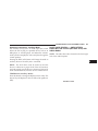
Airbag Warning Light
You will want to have the airbags ready to
inflate for your protection in an impact. While
the airbag system is designed to be maintenance free, if any of the following occurs, have
an authorized dealer service the system promptly:
• The Airbag Warning Light does not come on or flickers
during the six to eight seconds when the ignition
switch is first turned ON.
• The light remains on or flickers after the six to eight
second interval.
• The light flickers or comes on and remains on while
driving.
THINGS TO KNOW BEFORE STARTING YOUR VEHICLE
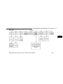
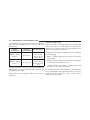
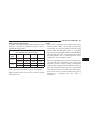
Event Data Recorder (EDR)
In the event of an accident, your vehicle is designed to
record up to five seconds of specific vehicle data parameters (see the following list) in an event data recorder
prior to the moment of airbag deployment, or near
deployment, and up to a quarter second of high-speed
deceleration data during and/or after airbag deployment. EDR data are ONLY recorded if an airbag deploys,
or nearly deploys, and are otherwise unavailable.
NOTE:
1. A near-deployment event occurs when the airbag
sensor detects severe vehicle deceleration usually indicative of a crash, but not severe enough to warrant airbag
deployment.
55
In conjunction with other data gathered during a complete accident investigation, the electronic data may be
used by Chrysler LLC and others to learn more about the
possible causes of crashes and associated injuries in order
to assess and improve vehicle performance. In addition
to crash investigations initiated by Chrysler LLC, such
investigations may be requested by customers, insurance
carriers, government officials, and professional crash
researchers, such as those associated with universities,
and with hospital and insurance organizations.
In the event that an investigation is undertaken by
Chrysler LLC (regardless of initiative), the company or its
designated representative will first obtain permission of
the appropriate custodial entity for the vehicle (usually
the vehicle owner or lessee) before accessing the elec2. Under certain circumstances, EDR data may not be
tronic data stored, unless ordered to download data by a
recorded (e.g., loss of battery power).
court with legal jurisdiction (i.e., pursuant to a warrant).
A copy of the data will be provided to the custodial entity
2
56
THINGS TO KNOW BEFORE STARTING YOUR VEHICLE
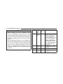
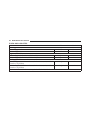
upon request. General data that does not identify par- • Diagnostic trouble code(s) and warning light status for
ticular vehicles or crashes may be released for incorpoelectronically-controlled safety systems, including the
ration in aggregate crash databases, such as those mainairbag system
tained by the U.S. government and various states. Data of
• Airbag disable light status (if equipped)
a potentially sensitive nature, such as would identify a
particular driver, vehicle, or crash, will be treated confi- • ⬙Time⬙ of airbag deployment (in terms of ignition
cycles and vehicle mileage)
dentially. Confidential data will not be disclosed by
Chrysler LLC to any third party except when:
• Airbag deployment level (if applicable)
1. Used for research purposes, such as to match data
• Impact velocity and angle
with a particular crash record in an aggregate database,
provided confidentiality of personal data is thereafter • Seat belt status
preserved,
• Brake status (service and parking brakes)
2. Used in defense of litigation involving a Chrysler LLC
• Accelerator status (including vehicle speed)
product,
• Engine control status (including engine speed)
3. Requested by police under a legal warrant, or
• Transmission gear selection
4. Otherwise required by law.
• Cruise control status
Data Parameters that May Be Recorded:
THINGS TO KNOW BEFORE STARTING YOUR VEHICLE
• Traction/stability control status
• Tire Pressure Monitoring System status (if equipped)
Child Restraint
Everyone in your vehicle needs to be buckled up all the
time, including babies and children. Every state in the
United States and all Canadian provinces require that
small children ride in proper restraint systems. This is the
law, and you can be prosecuted for ignoring it.
57
WARNING!
In a collision, an unrestrained child, even a tiny baby,
can become a projectile inside the vehicle. The force
required to hold even an infant on your lap could
become so great that you could not hold the child, no
matter how strong you are. The child and others
could be badly injured. Any child riding in your
vehicle should be in a proper restraint for the child’s
size.
Children 12 years and younger should ride properly
buckled up in a rear seat, if available. According to crash
There are different sizes and types of restraints for
statistics, children are safer when properly restrained in
children from newborn size to the child almost large
the rear seats rather than in the front.
enough for an adult safety belt. Always check the child
seat Owner’s Manual to ensure you have the correct seat
for your child. Use the restraint that is correct for your
child.
2
58
THINGS TO KNOW BEFORE STARTING YOUR VEHICLE
Infants and Child Restraints
“LATCH — Child Seat Anchorage System (Lower
Anchors and Tether for CHildren)” in this section.
• Safety experts recommend that children ride
rearward-facing in the vehicle until they are at least • Rearward-facing child seats must NEVER be used in
the front seat of a vehicle with the front passenger
one year old and weigh at least 20 lbs (9 kg). Two types
airbag unless the airbag is turned off. An airbag
of child restraints can be used rearward-facing, infant
deployment could cause severe injury or death to
carriers and convertible child seats.
infants in this position.
• The infant carrier is only used rearward-facing in the
vehicle. It is recommended for children who weigh up Older Children and Child Restraints
to about 20 lbs (9 kg). Convertible child seats can be Children who weigh more than 20 lbs (9 kg) and who are
used either rearward-facing or forward-facing in the older than one year can ride forward-facing in the
vehicle. Convertible child seats often have a higher vehicle. Forward-facing child seats and convertible child
weight limit in the rearward-facing direction than seats used in the forward-facing direction are for children
infant carriers do, so they can be used rearward-facing who weigh 20 to 40 lbs (9 to 18 kg) and who are older
by children who weigh more than 20 lbs (9 kg) but are than one year. These child seats are also held in the
less than one year old. Both types of child restraints are vehicle by the lap/shoulder belt or the LATCH child
held in the vehicle by the lap/shoulder belt or the restraint anchorage system. Refer to “LATCH — Child
LATCH child restraint anchorage system. Refer to Seat Anchorage System (Lower Anchors and Tether for
CHildren)” in this section.
THINGS TO KNOW BEFORE STARTING YOUR VEHICLE
The belt-positioning booster seat is for children weighing
more than 40 lbs (18 kg), but who are still too small to fit
the vehicle’s seat belts properly. If the child cannot sit
with knees bent over the vehicle’s seat cushion while the
child’s back is against the seatback, they should use a
belt-positioning booster seat. The child and beltpositioning booster seat are held in the vehicle by the
lap/shoulder belt.
Children too Large for Booster Seats
Children who are large enough to wear the shoulder belt
comfortably and whose legs are long enough to bend
over the front of the seat when their back is against the
seatback should use the lap/shoulder belt in a rear seat.
• Make sure that the child is upright in the seat.
• The lap portion should be low on the hips and as snug
as possible.
• Check belt fit periodically. A child’s squirming or
slouching can move the belt out of position.
59
• If the shoulder belt contacts the face or neck, move the
child closer to the center of the vehicle. Never allow a
child to put the shoulder belt under an arm or behind
their back.
NOTE:
For additional information, refer to
www.seatcheck.org or call 1–866–SEATCHECK. Canadian residents, should refer to Transport Canada’s website for additional information. http://www.tc.gc.ca/
roadsafety/childsafety/menu.htm
WARNING!
• Improper installation can lead to failure of an
infant or child restraint. It could come loose in a
collision. The child could be badly injured or
killed. Follow the manufacturer’s directions exactly when installing an infant or child restraint.
(Continued)
2
60
THINGS TO KNOW BEFORE STARTING YOUR VEHICLE
WARNING! (Continued)
• A rearward-facing child restraint should only be
used in a rear seat. A rearward-facing child restraint in the front seat may be struck by a deploying passenger airbag, which may cause severe or
fatal injury to the infant.
• Carefully follow the instructions that come with the
restraint. If you install the restraint improperly, it may
not work when you need it.
• Buckle the child into the seat according to the child
restraint manufacturer’s directions.
• When your child restraint is not in use, secure it in the
vehicle with the seat belt or remove it from the vehicle.
Here are some tips on getting the most out of your child
Do not leave it loose in the vehicle. In a sudden stop or
restraint:
collision, it could strike the occupants or seatbacks and
cause serious personal injury.
• Before buying any restraint system, make sure that it
has a label certifying that it meets all applicable Safety LATCH — Child Seat Anchorage System (Lower
Standards. We also recommend that you make sure Anchors and Tether for CHildren)
that you can install the child restraint in the vehicle Your vehicle’s rear seat is equipped with the child
where you will use it before you buy it.
restraint anchorage system called LATCH. The LATCH
• The restraint must be appropriate for your child’s system provides for the installation of the child restraint
weight and height. Check the label on the restraint for without using the vehicle’s seat belts, instead securing
weight and height limits.
THINGS TO KNOW BEFORE STARTING YOUR VEHICLE
61
the child restraint using lower anchorages and upper child seats. You should NEVER install LATCHtether straps from the child restraint to the vehicle compatible child seats so that two seats share a common
lower anchorage. If installing child seats in adjacent
structure.
rear-seating positions, or if your child restraints are not
LATCH-compatible child restraint systems are now availLATCH-compatible, install the restraints using the vehiable. However, because the lower anchorages are to be
cle’s seat belts.
introduced over a period of years, child restraint systems
having attachments for those anchorages will continue to
have features for installation using the vehicle’s seat
belts. Child restraints having tether straps and hooks for
connection to the top tether anchorages, have been
available for some time. For some older child restraints,
many child restraint manufacturers offer add-on tether
strap kits or retrofit kits. You are urged to take advantage
of all the available attachments provided with your child
restraint in any vehicle.
All three rear-seating positions have lower anchorages
that are capable of accommodating LATCH-compatible
LATCH Anchorages
2
62
THINGS TO KNOW BEFORE STARTING YOUR VEHICLE
Installing the LATCH-Compatible Child Restraint
System
We urge you to follow the manufacturer’s directions
carefully when installing your child restraint. Not all
child restraint systems will be installed as described here.
Again, carefully follow the installation instructions that
are provided with the child restraint system.
window. These tether strap anchorages are under a
plastic cover with this symbol on it.
Many, but not all restraint systems will be equipped with
separate straps on each side, with each having a hook or
connector for attachment to the lower anchorage and a
means of adjusting the tension in the strap. Forwardfacing toddler restraints and some rear-facing infant
The rear seat lower anchorages are round bars restraints will also be equipped with a tether strap, a
located at the rear of the seat cushion where it hook for attachment to the tether strap anchorage and a
meets the seatback and are just visible when means of adjusting the tension of the strap.
you lean into the rear seat to install the child
You will first loosen the adjusters on the lower straps and
restraint. You will easily feel them if you run your finger
on the tether strap so that you can more easily attach the
along the intersection of the seatback and seat cushion
hooks or connectors to the vehicle anchorages. Next,
surfaces.
attach the lower hooks or connectors over the top of the
In addition, there are tether strap anchorages seatcover material. Then rotate the tether anchorage
behind each rear seating position located in the cover directly behind the seat where you are placing the
panel between the rear seatback and the rear child restraint and attach the tether strap to the anchorage, being careful to route the tether strap to provide the
THINGS TO KNOW BEFORE STARTING YOUR VEHICLE
most direct path between the anchor and the child
restraint. Finally, tighten all three straps as you push the
child restraint rearward and downward into the seat,
removing slack in the straps according to the child
restraint manufacturer’s instructions.
NOTE:
• Ensure that the tether strap does not slip into the
opening between the seatbacks as you remove slack in
the strap.
• When using the LATCH attaching system to install a
child restraint, please ensure that all seat belts not
being used for occupant restraints are stowed and out
of reach of children. It is recommended that before
installing the child restraint, buckle the seat belt so the
seat belt is tucked behind the child restraint and out of
reach. If the buckled seat belt interferes with the child
restraint installation, instead of tucking the seat belt
behind the child restraint, route the seat belt through
63
the child restraint belt path and then buckle it. This
should stow the seat belt out of the reach of an
inquisitive child. Remind all children in the vehicle
that the seat belts are not toys and should not be
played with, and never leave your child unattended in
the vehicle.
WARNING!
Improper installation of a child restraint to the
LATCH anchorages can lead to failure of an infant or
child restraint. The child could be badly injured or
killed. Follow the manufacturer’s directions exactly
when installing an infant or child restraint.
Installing Child Restraints Using the Vehicle Seat
Belt
The passenger seat belts are equipped with either cinching latch plates or automatic locking retractors, which are
designed to keep the lap portion tight around the child
2
64
THINGS TO KNOW BEFORE STARTING YOUR VEHICLE
restraint so that it is not necessary to use a locking clip.
Pulling up on the shoulder portion of the lap/shoulder
belt will tighten the belt. The cinching latch plate will
keep the belt tight; however, any seat belt system will
loosen with time, so check the belt occasionally and pull
it tight if necessary.
The seat belt must be in the Automatic Locking Mode in
order to enable a child restraint to be tightly installed.
Refer to “Automatic Locking Mode” in this section. A
locking clip should not be necessary once the automatic
locking feature is enabled. Position the shoulder and lap
belt on the child restraint. The automatic locking retractor
is activated by first attaching the child seat, then pulling
all of the webbing out of the retractor, then allowing the
webbing to retract back into the retractor. Tighten webbing. To release, simply unbuckle the seat belt by depressing the button, allowing the webbing to retract into
the retractor.
In the rear seat, you may have trouble tightening the
lap/shoulder belt on the child restraint because the
buckle or latch plate is too close to the belt path opening
on the restraint. Disconnect the latch plate from the
buckle and twist the short buckle end belt several times
to shorten it. Insert the latch plate into the buckle with the
release button facing out.
If the belt still cannot be tightened, or if pulling and
pushing on the restraint loosens the belt, you may need
to do something more. Disconnect the latch plate from
the buckle, turn the buckle around, and insert the latch
plate into the buckle again. If you still cannot make the
child restraint secure, try a different seating position.
To attach a child restraint tether strap:
1. Rotate the cover over the anchor directly behind the
seat where you are placing the child restraint.
THINGS TO KNOW BEFORE STARTING YOUR VEHICLE
65
NOTE: Ensure that the tether strap does not slip into the
opening between the seatbacks as you remove slack in
the strap.
WARNING!
An incorrectly anchored tether strap could lead to
increased head motion and possible injury to the
child. Use only the anchor positions directly behind
the child seat to secure a child restraint top tether
strap.
Transporting Pets
Airbags deploying in the front seat could harm your pet.
2. Route the tether strap to provide the most direct path
An unrestrained pet will be thrown about and possibly
for the strap between the anchor and the child seat.
injured, or injure a passenger during panic braking or in
3. Attach the tether strap hook (A) of the child restraint to a collision.
the anchor (B) and remove slack in the tether strap
Pets should be restrained in the rear seat in pet harnesses
according to the child restraint manufacturer’s instrucor pet carriers that are secured by seat belts.
tions.
Tether Strap Mounting
2
66
THINGS TO KNOW BEFORE STARTING YOUR VEHICLE
consistent with anticipated climate and conditions under
ENGINE BREAK-IN RECOMMENDATIONS
A long break-in period is not required for the drivetrain which vehicle operations will occur. The recommended
(engine, transmission, and rear axle) in your new vehicle. viscosity and quality grades is shown in Section 7.
Drive moderately during the first 500 mi (800 km). After
the initial 60 mi (100 km), speeds up to 50 or 55 mph (80
or 90 km/h) are desirable.
CAUTION!
Never use Non-Detergent Oil or Straight Mineral Oil
in the engine or damage may result.
While cruising, brief full-throttle acceleration within the
limits of local traffic laws contributes to a good break-in.
NOTE: A new engine may consume some oil during its
However, wide-open throttle acceleration in low gear can
first few thousand miles (kilometers) of operation. This
be detrimental and should be avoided.
should be considered a normal part of the break-in and
The engine oil, transmission fluid, and axle lubricant not interpreted as an indication of difficulty.
installed at the factory is high-quality and energyconserving. Oil, fluid, and lubricant changes should be
THINGS TO KNOW BEFORE STARTING YOUR VEHICLE
SAFETY TIPS
67
Exhaust Gas
Transporting Passengers
NEVER TRANSPORT PASSENGERS IN THE CARGO
AREA.
WARNING!
• It is extremely dangerous to ride in a cargo area,
inside or outside of a vehicle. In a collision, people
riding in these areas are more likely to be seriously injured or killed.
• Do not allow people to ride in any area of your
vehicle that is not equipped with seats and seat
belts.
• Be sure everyone in your vehicle is in a seat and
using a seat belt properly.
WARNING!
Exhaust gases can injure or kill. They contain carbon
monoxide (CO), which is colorless and odorless.
Breathing it can make you unconscious and can
eventually poison you. To avoid breathing (CO)
follow these safety tips:
Do not run the engine in a closed garage or in confined
areas any longer than needed to move your vehicle in or
out of the area.
If it is necessary to sit in a parked vehicle with the engine
running, adjust your heating or cooling controls to force
outside air into the vehicle. Set the blower at high speed.
2
68
THINGS TO KNOW BEFORE STARTING YOUR VEHICLE
If you are required to drive with the trunk/liftgate open, Safety Checks You Should Make Inside the
make sure that all windows are closed and the climate Vehicle
control BLOWER switch is set at high speed. DO NOT
Seat Belts
use the recirculation mode.
Inspect the belt system periodically, checking for cuts,
The best protection against carbon monoxide entry into frays, and loose parts. Damaged parts must be replaced
the vehicle body is a properly maintained engine exhaust immediately. Do not disassemble or modify the system.
system.
Front seat belt assemblies must be replaced after a
Whenever a change is noticed in the sound of the exhaust collision. Rear seat belt assemblies must be replaced after
system, when exhaust fumes can be detected inside the a collision if they have been damaged (i.e., bent retractor,
vehicle, or when the underside or rear of the vehicle is torn webbing, etc.). If there is any question regarding belt
damaged, have a competent mechanic inspect the com- or retractor condition, replace the belt.
plete exhaust system and adjacent body areas for broken,
Airbag Warning Light
damaged, deteriorated, or mispositioned parts. Open
The light should come on and remain on for six to eight
seams or loose connections could permit exhaust fumes
seconds as a bulb check when the ignition switch is first
to seep into the passenger compartment. In addition,
turned ON. If the light is not lit during starting, see your
inspect the exhaust system each time the vehicle is raised
authorized dealer. If the light stays on, flickers, or comes
for lubrication or oil change. Replace as required.
on while driving, have the system checked by an authorized dealer.
THINGS TO KNOW BEFORE STARTING YOUR VEHICLE
Defroster
Check operation by selecting the defrost mode and place
the blower control on high speed. You should be able to
feel the air directed against the windshield. See your
authorized dealer for service if your defroster is
inoperable.
Periodic Safety Checks You Should Make Outside
the Vehicle
69
Lights
Have someone observe the operation of exterior lights
while you work the controls. Check turn signal and high
beam indicator lights on the instrument panel.
Door Latches
Check for positive closing, latching, and locking.
Fluid Leaks
Check area under vehicle after overnight parking for fuel,
engine coolant, oil, or other fluid leaks. Also, if gasoline
Tires
Examine tires for excessive tread wear and uneven wear fumes are detected or if fuel, power steering fluid, or
patterns. Check for stones, nails, glass, or other objects brake fluid leaks are suspected, the cause should be
lodged in the tread. Inspect the tread and sidewall for located and corrected immediately.
cuts and cracks. Check the wheel nuts for tightness.
Check the tires (including spare) for proper pressure.
2
71
UNDERSTANDING THE FEATURES OF YOUR VEHICLE
CONTENTS
䡵 Mirrors . . . . . . . . . . . . . . . . . . . . . . . . . . . . . . 75
▫ Automatic Dimming Mirror — If Equipped . . . 75
▫ Outside Mirrors . . . . . . . . . . . . . . . . . . . . . . 75
▫ Outside Mirrors Folding Feature . . . . . . . . . . 76
▫ Power Mirrors . . . . . . . . . . . . . . . . . . . . . . . 76
▫ Heated Mirrors — If Equipped . . . . . . . . . . . . 77
▫ Vanity Mirrors . . . . . . . . . . . . . . . . . . . . . . . 77
▫ Illuminated Vanity Mirrors . . . . . . . . . . . . . . 77
▫ Slide-On-Rod And Extender Features Of Sun
Visor . . . . . . . . . . . . . . . . . . . . . . . . . . . . . . 77
䡵 uconnect威 phone — If Equipped . . . . . . . . . . . . 78
▫ Operation . . . . . . . . . . . . . . . . . . . . . . . . . . 80
▫ Phone Call Features . . . . . . . . . . . . . . . . . . . 88
▫ uconnect威 phone Features . . . . . . . . . . . . . . . 91
▫ Advanced Phone Connectivity . . . . . . . . . . . . 96
▫ Things You Should Know About Your
uconnect威 phone . . . . . . . . . . . . . . . . . . . . . . 98
▫ General Information . . . . . . . . . . . . . . . . . . 106
3
72
UNDERSTANDING THE FEATURES OF YOUR VEHICLE
䡵 Voice Recognition (VR) System —
If Equipped . . . . . . . . . . . . . . . . . . . . . . . . . . 106
▫ Voice Recognition (VR) System Operation . . . 106
▫ Commands . . . . . . . . . . . . . . . . . . . . . . . . 108
▫ Voice Training . . . . . . . . . . . . . . . . . . . . . . . 111
䡵 To Open And Close The Hood . . . . . . . . . . . . 117
䡵 Lights
. . . . . . . . . . . . . . . . . . . . . . . . . . . . . 119
▫ Headlight Switch . . . . . . . . . . . . . . . . . . . . 119
▫ Automatic Headlights — If Equipped . . . . . . 120
䡵 Seats . . . . . . . . . . . . . . . . . . . . . . . . . . . . . . . 111
▫ Headlights On With Wipers (Available With
Auto Headlights Only) . . . . . . . . . . . . . . . . 120
▫ Easy Entry Seats . . . . . . . . . . . . . . . . . . . . . . 111
▫ Headlight Time Delay . . . . . . . . . . . . . . . . . 120
▫ Power Seats . . . . . . . . . . . . . . . . . . . . . . . . 112
▫ Daytime Running Lights — If Equipped . . . . 121
▫ Manual Front Seatback Recline . . . . . . . . . . . 113
▫ Lights-On Reminder . . . . . . . . . . . . . . . . . . 121
▫ Lumbar Support . . . . . . . . . . . . . . . . . . . . . 114
▫ Fog Lights — If Equipped . . . . . . . . . . . . . . 121
▫ Head Restraints . . . . . . . . . . . . . . . . . . . . . 114
▫ Multifunction Lever . . . . . . . . . . . . . . . . . . 122
▫ Heated Seats . . . . . . . . . . . . . . . . . . . . . . . 115
▫ Overhead Console Map/Reading Lights . . . . 123
▫ Folding Rear Seat . . . . . . . . . . . . . . . . . . . . 116
▫ Interior Lights . . . . . . . . . . . . . . . . . . . . . . 123
UNDERSTANDING THE FEATURES OF YOUR VEHICLE
73
䡵 Windshield Wipers And Washers . . . . . . . . . . 125
▫ To Accelerate For Passing . . . . . . . . . . . . . . 131
▫ Intermittent Wiper System . . . . . . . . . . . . . . 125
䡵 Overhead Console . . . . . . . . . . . . . . . . . . . . . 132
▫ Mist Feature . . . . . . . . . . . . . . . . . . . . . . . . 126
▫ Courtesy/Reading Lights . . . . . . . . . . . . . . 132
▫ Windshield Washers . . . . . . . . . . . . . . . . . . 126
▫ Sunglasses Storage . . . . . . . . . . . . . . . . . . . 132
▫ Headlights On With Wipers (Available With
Auto Headlights Only) . . . . . . . . . . . . . . . . 126
䡵 Garage Door Opener — If Equipped . . . . . . . . 133
䡵 Tilt/Telescoping Steering Column . . . . . . . . . . 127
䡵 Electronic Speed Control . . . . . . . . . . . . . . . . 128
▫ To Activate . . . . . . . . . . . . . . . . . . . . . . . . . 129
▫ Programming HomeLink威 . . . . . . . . . . . . . . 134
▫ Gate Operator/Canadian Programming . . . . 137
▫ Using HomeLink威 . . . . . . . . . . . . . . . . . . . 137
▫ To Set A Desired Speed . . . . . . . . . . . . . . . . 129
▫ Reprogramming A Single
HomeLink威 Button . . . . . . . . . . . . . . . . . . . 138
▫ To Deactivate . . . . . . . . . . . . . . . . . . . . . . . 130
▫ Security . . . . . . . . . . . . . . . . . . . . . . . . . . . 138
▫ To Resume Speed . . . . . . . . . . . . . . . . . . . . 130
▫ Troubleshooting Tips . . . . . . . . . . . . . . . . . . 138
▫ To Vary The Speed Setting . . . . . . . . . . . . . . 130
▫ General Information . . . . . . . . . . . . . . . . . . 139
3
74
UNDERSTANDING THE FEATURES OF YOUR VEHICLE
䡵 Power Sunroof — If Equipped . . . . . . . . . . . . 139
▫ Ignition Off Operation . . . . . . . . . . . . . . . . . 142
▫ Opening Sunroof — Partially . . . . . . . . . . . . 140
▫ Sunroof Fully Closed . . . . . . . . . . . . . . . . . . 142
▫ Opening Sunroof — Express . . . . . . . . . . . . 140
䡵 Electrical Power Outlets . . . . . . . . . . . . . . . . . 142
▫ Closing Sunroof — Partially . . . . . . . . . . . . . 140
䡵 Cupholders . . . . . . . . . . . . . . . . . . . . . . . . . . 144
▫ Closing Sunroof — Express . . . . . . . . . . . . . 141
▫ Front Cupholders . . . . . . . . . . . . . . . . . . . . 144
▫ Pinch Protect Feature . . . . . . . . . . . . . . . . . 141
▫ Rear Cupholders . . . . . . . . . . . . . . . . . . . . . 145
▫ Pinch Protect Override . . . . . . . . . . . . . . . . 141
䡵 Console Features . . . . . . . . . . . . . . . . . . . . . . 146
▫ Venting Sunroof — Express . . . . . . . . . . . . . 141
▫ Sliding Center Console Armrest . . . . . . . . . . 146
▫ Sunshade Operation . . . . . . . . . . . . . . . . . . 141
▫ Console Storage . . . . . . . . . . . . . . . . . . . . . 146
▫ Wind Buffeting . . . . . . . . . . . . . . . . . . . . . . 142
䡵 Rear Window Features . . . . . . . . . . . . . . . . . . 147
▫ Sunroof Maintenance . . . . . . . . . . . . . . . . . 142
▫ Rear Window Defroster . . . . . . . . . . . . . . . . 147
UNDERSTANDING THE FEATURES OF YOUR VEHICLE
MIRRORS
75
CAUTION!
Automatic Dimming Mirror — If Equipped
This mirror automatically adjusts for headlight glare
from vehicles behind you. You can turn the feature on or
off by pressing the button at the base of the mirror. A light
next to the button will illuminate to indicate when the
dimming feature is activated.
To avoid damage to the mirror during cleaning, never
spray any cleaning solution directly onto the mirror.
Apply the solution onto a clean cloth and wipe the
mirror clean.
Outside Mirrors
To receive maximum benefit, adjust the outside mirror(s)
to center on the adjacent lane of traffic and a slight
overlap of the view obtained from the inside mirror.
NOTE: The passenger-side convex outside mirror will
give a much wider view to the rear, and especially of the
lane next to your vehicle.
Automatic Dimming Mirror
3
76
UNDERSTANDING THE FEATURES OF YOUR VEHICLE
WARNING!
Vehicles and other objects seen in the passenger-side
convex mirror will look smaller and farther away
than they really are. Relying too much on your
passenger-side convex mirror could cause you to
collide with another vehicle or other object. Use your
inside mirror when judging the size or distance of a
vehicle seen in the passenger-side convex mirror.
Outside Mirrors Folding Feature
All models have exterior mirrors that are hinged. The
Power Mirror Control
hinge allows the mirror to pivot forward and rearward to
resist damage. The hinge has three detent positions: full After selecting a mirror, move the knob in the same
direction you want the mirror to move. Use the center off
forward, full rearward, and normal.
position to guard against accidentally moving a mirror
Power Mirrors
position.
The power mirror switch is located on the driver’s door
trim panel next to the power door lock switch. A rotary
knob selects the left mirror, right mirror, or off position.
UNDERSTANDING THE FEATURES OF YOUR VEHICLE
77
Heated Mirrors — If Equipped
These mirrors are heated to melt frost or ice. This
feature is activated whenever you turn on the rear
window defroster. Refer to “Rear Window Features” in
this section, for further information.
Vanity Mirrors
A vanity mirror is located on the sun visor. To use the
mirror, rotate the sun visor downward and swing the
mirror cover upward.
Illuminated Vanity Mirrors
An illuminated vanity mirror is on the sun visor. To use
Illuminated Vanity Mirror
the mirror, rotate the sun visor downward and swing the
mirror cover upward. The light turns on automatically. Slide-On-Rod and Extender Features of Sun Visor
To use the slide-on-rod feature of the sun visor, rotate the
Close the mirror cover to turn off the light.
sun visor downward and swing the sun visor so it is
parallel to the side window, grabbing the sun visor with
3
78
UNDERSTANDING THE FEATURES OF YOUR VEHICLE
your left hand pull rearwards until the sun visor is in the uconnect姞 phone — IF EQUIPPED
desired position. To use the extender feature of the sun
NOTE: The sales code RER and REU radios contain an
visor, grab the extender which is located at the rear of the
integrated uconnect威 phone. Refer to your “Navigation
visor and pull rearward.
User’s Manual” for uconnect威 phone operating instructions for these radios. Radio sales code can be located
on the lower right corner of the Radio faceplate.
uconnect威 phone is a voice-activated, hands-free, invehicle communications system. uconnect威 allows you to
dial a phone number with your cellular phone using
simple voice commands (e.g., ⬙Call” ѧ “Mike” ѧ”Work⬙ or
⬙Dial” ѧ “248-555-1212⬙). Your cellular phone’s audio is
transmitted through your vehicle’s audio system; the
system will automatically mute your radio when using
the uconnect威 phone.
Slide-On-Rod Extender
NOTE: The uconnect威 phone requires a cellular phone
equipped with the Bluetooth威 ⬙Hands-Free Profile,⬙ Version 0.96 or higher. See the uconnect威 website for supported phones.
UNDERSTANDING THE FEATURES OF YOUR VEHICLE
79
For uconnect威 customer support, visit the following it your purse, pocket, or briefcase), as long as your phone
is turned on and has been paired to the vehicle’s
websites:
uconnect威 phone. The uconnect威 phone allows up to
• www.chrysler.com/uconnect
seven cellular phones to be linked to the system. Only
one linked (or paired) cellular phone can be used with the
• www.dodge.com/uconnect
system at a time. The system is available in English,
• www.jeep.com/uconnect
Spanish, or French languages.
• or call 1–877–855–8400
Phone Button
uconnect威 allows you to transfer calls between the sysThe rearview mirror contains the microphone
tem and your cellular phone as you enter or exit your
for the system (depending on the type of
mirror and radio equipped), and either the
vehicle and enables you to mute the system’s microphone
for private conversation.
radio or the mirror has the two control buttons
(PHONE Button and VOICE RECOGNITION button)
The uconnect威 phone is driven through your Bluetooth威
that will enable you to access the system.
“Hands-Free Profile” cellular phone. uconnect威 features
Bluetooth威 technology - the global standard that enables Voice Recognition Button
different electronic devices to connect to each other
Actual button location may vary with the rawithout wires or a docking station, so uconnect威 phone
dio. The individual buttons are described in the
works no matter where you stow your cellular phone (be
“Operation” section.
3
80
UNDERSTANDING THE FEATURES OF YOUR VEHICLE
The uconnect威 phone can be used with any Hands-Free
Profile certified Bluetooth威 cellular phone. See the
uconnect威 website for supported phones. If your cellular
phone supports a different profile (e.g., Headset Profile)
you may not be able to use any uconnect威 phone
features. Refer to your cellular service provider or the
phone manufacturer for details.
Operation
Voice commands can be used to operate the uconnect威
phone and to navigate through the uconnect威 phone
menu structure. Voice commands are required after most
uconnect威 phone prompts. You will be prompted for a
specific command and then guided through the available
options.
The uconnect威 phone is fully integrated with the vehi- • Prior to giving a voice command, one must wait for
the beep, which follows the ⬙Ready⬙ prompt or another
cle’s audio system. The volume of the uconnect威 phone
prompt.
can be adjusted either from the radio volume control
knob or from the steering wheel radio control (right
• For certain operations, compound commands can be
switch), if so equipped.
used. For example, instead of saying ⬙Setup⬙ and then
⬙Phone Pairing,⬙ the following compound command
The radio display will be used for visual prompts from
can be said: ⬙Setup Phone Pairing.⬙
the uconnect威 phone such as ⬙CELL⬙ or caller ID on
certain radios.
• For each feature explanation in this section, only the
combined form of the voice command is given. You
can also break the commands into parts and say each
part of the command when you are asked for it. For
UNDERSTANDING THE FEATURES OF YOUR VEHICLE
example, you can use the combined form voice command ⬙Phonebook New Entry,⬙ or you can break the
combined form command into two voice commands:
⬙Phonebook⬙ and ⬙New Entry.⬙ Please remember, the
uconnect威 phone works best when you talk in a
normal conversational tone, as if speaking to someone
sitting a few feet/meters away from you.
Voice Command Tree
Refer to “Voice Tree” in this section.
Help Command
If you need assistance at any prompt, or if you want to
know your options at any prompt, say ⬙Help⬙ following
the beep. The uconnect威 phone will play all the options at
any prompt if you ask for help.
81
Cancel Command
At any prompt, after the beep, you can say ⬙Cancel⬙ and
you will be returned to the main menu. However, in a
few instances the system will take you back to the
previous menu.
Pair (Link) uconnect威 phone to a Cellular Phone
To begin using your uconnect威 phone, you must pair
your compatible Bluetooth威 enabled cellular phone.
To complete the pairing process, you will need to reference your cellular phone Owner’s Manual. The
uconnect威 website may also provide detailed instructions
for pairing.
The following are general phone to uconnect威 phone
pairing instructions:
To activate the uconnect威 phone from idle, simply press
• Press the PHONE button to begin.
the PHONE button and follow the audible prompts for
directions. All uconnect威 phone sessions begin with a • After the ⬙Ready⬙ prompt and the following beep, say
⬙Setup Phone Pairing.⬙
press of the PHONE button on the radio control head.
3
82
UNDERSTANDING THE FEATURES OF YOUR VEHICLE
• When prompted, after the beep, say ⬙Pair a Phone⬙ and
follow the audible prompts.
• You will be asked to say a four-digit Personal Identification Number (PIN), which you will later need to
enter into your cellular phone. You can enter any
four-digit PIN. You will not need to remember this PIN
after the initial pairing process.
phone to use if multiple cellular phones are in the
vehicle at the same time. For example, if priority three
and priority five phones are present in the vehicle, the
uconnect威 phone will use the priority three cellular
phone when you make a call. You can select to use a
lower priority cellular phone at any time (refer to
⬙Advanced Phone Connectivity⬙ in this section).
Dial by Saying a Number
• For identification purposes, you will be prompted to
give the uconnect威 phone a name for your cellular • Press the PHONE button to begin.
phone. Each cellular phone that is paired should be
• After the ⬙Ready⬙ prompt and the following beep, say
given a unique phone name.
⬙Dial.⬙
• You will then be asked to give your cellular phone a
• The system will prompt you to say the number you
priority level between one and seven, with one being
want to call.
the highest priority. You can pair up to seven cellular
phones to your uconnect威 phone. However, at any • For example, you can say ⬙234-567-8901⬙.
given time, only one cellular phone can be in use,
connected to your uconnect威 phone. The priority
allows the uconnect威 phone to know which cellular
UNDERSTANDING THE FEATURES OF YOUR VEHICLE
83
• The uconnect威 phone will confirm the phone number • The uconnect威 system will confirm the name and then
and then dial. The number will appear in the display
dial the corresponding phone number, which may
of certain radios.
appear in the display of certain radios.
Call by Saying a Name
Add Names to Your uconnect威 Phonebook
• Press the PHONE button to begin.
NOTE: Adding names to the uconnect威 phonebook is
recommended when the vehicle is not in motion.
• After the ⬙Ready⬙ prompt and the following beep, say
• Press the PHONE button to begin.
“Call.⬙
• The system will prompt you to say the name of the • After the ⬙Ready⬙ prompt and the following beep, say
person you want to call.
⬙Phonebook New Entry.⬙
• After the ⬙Ready⬙ prompt and the following beep, say • When prompted, say the name of the new entry. Use of
the name of the person you want to call. For example,
long names helps the voice recognition and it is
you can say ⬙John Doe,⬙ where John Doe is a previrecommended. For example, say ⬙Robert Smith⬙ or
ously stored name entry in the uconnect威 phonebook
⬙Robert⬙ instead of ⬙Bob.⬙
or downloaded phonebook. To learn how to store a
name in the phonebook, refer to ⬙Add Names to Your
uconnect威 Phonebook,⬙ in the phonebook.
3
84
UNDERSTANDING THE FEATURES OF YOUR VEHICLE
• When prompted, enter the number designation (e.g.,
⬙Home,⬙ ⬙Work,⬙ ⬙Mobile,⬙ or ⬙Pager⬙). This will allow
you to store multiple numbers for each phonebook
entry, if desired.
Phonebook Download – Automatic Phonebook
Transfer From Cellular Phone
If equipped and specifically supported by your phone,
uconnect威 phone automatically downloads names (text
names) and number entries from the cellular phone’s
• When prompted, recite the phone number for the
phonebook. Specific Bluetooth威 Phones with Phone Book
phonebook entry that you are adding.
Access Profile may support this feature. See uconnect威
After you are finished adding an entry into the phone- website for supported phones.
book, you will be given the opportunity to add more
• To call a name from downloaded (or uconnect威)
phone numbers to the current entry or to return to the
Phonebook, follow the procedure in “Call by Saying a
main menu.
Name” section.
The uconnect威 phone will allow you to enter up to 32
• Automatic download and update, if supported, begins
names in the phonebook with each name having up to
as soon as the Bluetooth威 wireless phone connection is
four associated phone numbers and designations. Each
made to the uconnect威 phone, for example, after you
language has a separate 32-name phonebook accessible
start the vehicle.
only in that language. In addition, if equipped and
supported by your phone, uconnect威 phone automati- • A maximum of 1000 entries per phone will be downloaded and updated every time a phone is connected
cally downloads your cellular phone’s phonebook.
to the uconnect威 phone.
UNDERSTANDING THE FEATURES OF YOUR VEHICLE
85
• Depending on the maximum number of entries downloaded, there may be a short delay before the latest
downloaded names can be used. Until then, if available, the previous downloaded phonebook is available
for use.
Phonebook Download — Single Entry
If equipped and supported by your phone, uconnect威
phone allows the user to download entries from their
phone via Bluetooth威. To use this feature, press the
PHONE button and say “Phonebook Download.” The
system prompts, “Ready to accept “V” card entry via
• Only the phonebook of the currently connected celluBluetooth威…” The system is now ready to accept phonelar phone is accessible.
book entries from your phone using the Bluetooth威
• Only the cellular phone’s phonebook is downloaded. Object Exchange Profile (OBEX). Please see your phone
SIM card phonebook is not part of the Mobile phone- Owner’s Manual for specific instructions on how to send
book.
these entries from your phone.
• This downloaded phonebook cannot be edited or NOTE:
deleted on the uconnect威 phone. These can only be • The phone handset must support Bluetooth威 OBEX
transfers of phonebook entries to use this feature.
edited on the cellular phone. The changes are transferred and updated to uconnect威 phone on the next
• Some phones cannot send phonebook entries if they
phone connection.
are already connected to any system via Bluetooth威,
and you may see a message on the phone display that
the Bluetooth威 link is busy. In this case, the user must
3
86
UNDERSTANDING THE FEATURES OF YOUR VEHICLE
first disconnect or drop the Bluetooth威 connection to • You will then be asked for the name of the phonebook
the uconnect威 phone, and then send the address book
entry that you wish to edit.
entry via Bluetooth威. Please see your phone Owner’s
• Next, choose the number designation (home, work,
Manual for specific instructions on how to drop the
cellular, or pager) that you wish to edit.
Bluetooth威 connection.
• When prompted, recite the new phone number for the
• If the phonebook entry is longer than 24 characters, it
phonebook entry that you are editing.
will only use the first 24 characters.
After you are finished editing an entry in the phonebook,
Edit uconnect威 Phonebook Entries
you will be given the opportunity to edit another entry in
NOTE:
the phonebook, call the number you just edited, or return
• Editing names in the phonebook is recommended to the main menu.
when the vehicle is not in motion.
⬙Phonebook Edit⬙ can be used to add another phone
• Automatic downloaded phonebook entries cannot be number to a name entry that already exists in the
deleted or edited.
phonebook. For example, the entry John Doe may have a
cellular and a home number, but you can add ”John
• Press the PHONE button to begin.
Doe’s” work number later using the ⬙Phonebook Edit⬙
• After the ⬙Ready⬙ prompt and the following beep, say feature.
⬙Phonebook Edit.⬙
UNDERSTANDING THE FEATURES OF YOUR VEHICLE
87
• After you enter the name, the uconnect威 phone will
ask you which designation you wish to delete: home,
NOTE: Editing phonebook entries is recommended
work, cellular, pager, or all. Say the designation you
when the vehicle is not in motion.
wish to delete.
• Press the PHONE button to begin.
• Note that only the phonebook entry in the current
• After the ⬙Ready⬙ prompt and the following beep, say
language is deleted.
⬙Phonebook Delete.⬙
• Automatic downloaded phonebook entries cannot be
• After you enter the Phonebook Delete menu, you will
deleted or edited.
then be asked for the name of the entry that you wish
Delete/Erase “All” uconnect威 Phonebook Entries
to delete. You can either say the name of a phonebook
entry that you wish to delete or you can say ⬙List • Press the PHONE button to begin.
Names⬙ to hear a list of the entries in the phonebook
• After the ⬙Ready⬙ prompt and the following beep, say
from which you choose. To select one of the entries
⬙Phonebook Erase All.⬙
from the list, press the VOICE RECOGNITION button
while the uconnect威 phone is playing the desired entry • The uconnect威 phone will ask you to verify that you
wish to delete all the entries from the phonebook.
and say ⬙Delete.⬙
Delete uconnect威 Phonebook Entry
• After confirmation, the phonebook entries will be
deleted.
3
88
UNDERSTANDING THE FEATURES OF YOUR VEHICLE
• Note that only the phonebook in the current language • The uconnect威 phone will then prompt you as to the
is deleted.
number designation you wish to call.
• Automatic downloaded phonebook entries cannot be • The selected number will be dialed.
deleted or edited.
Phone Call Features
List All Names in the uconnect威 Phonebook
The following features can be accessed through the
uconnect威 phone if the feature(s) are available on your
• Press the PHONE button to begin.
cellular service plan. For example, if your cellular service
• After the ⬙Ready⬙ prompt and the following beep, say plan provides three-way calling, this feature can be
⬙Phonebook List Names.⬙
accessed through the uconnect威 phone. Check with your
cellular service provider for the features that you have.
• The uconnect威 phone will play the names of all the
phonebook entries, including the downloaded phone- Answer or Reject an Incoming Call - No Call
Currently in Progress
book entries, if available.
When you receive a call on your cellular phone, the
• To call one of the names in the list, press the VOICE
uconnect威 phone will interrupt the vehicle audio system, if
RECOGNITION button during the playing of the
on, and will ask if you would like to answer the call. Press
desired name, and say ⬙Call.⬙
the PHONE button to accept the call. To reject the call,
NOTE: The user can also exercise ⬙Edit⬙ or ⬙Delete⬙ press and hold the PHONE button until you hear a single
operations at this point.
beep, indicating that the incoming call was rejected.
UNDERSTANDING THE FEATURES OF YOUR VEHICLE
Answer or Reject an Incoming Call - Call
Currently in Progress
If a call is currently in progress and you have another
incoming call, you will hear the same network tones for
call waiting that you normally hear when using your
cellular phone. Press the PHONE button to place the
current call on hold and answer the incoming call.
89
to ⬙Toggling Between Calls⬙ in this section. To combine two
calls, refer to ⬙Conference Call⬙ in this section.
Place/Retrieve a Call From Hold
To put a call on hold, press the PHONE button until you
hear a single beep. This indicates that the call is on hold.
To bring the call back from hold, press and hold the
PHONE button until you hear a single beep.
NOTE: The uconnect威 phone compatible phones in the
Toggling Between Calls
market today do not support rejecting an incoming call
If two calls are in progress (one active and one on hold),
when another call is in progress. Therefore, the user can
press the PHONE button until you hear a single beep,
only answer an incoming call or ignore it.
indicating that the active and hold status of the two calls
Making a Second Call While Current Call is in
have switched. Only one call can be placed on hold at a
Progress
time.
To make a second call while you are currently on a call,
Conference Call
press the VOICE RECOGNITION button and say ⬙Dial⬙ or
When two calls are in progress (one active and one on
⬙Call⬙ followed by the phone number or phonebook entry
hold), press and hold the PHONE button until you hear
you wish to call. The first call will be on hold while the
a double beep indicating that the two calls have been
second call is in progress. To go back to the first call, refer
joined into one conference call.
3
90
UNDERSTANDING THE FEATURES OF YOUR VEHICLE
Three-Way Calling
To initiate three-way calling, press the VOICE RECOGNITION button while a call is in progress, and make a
second phone call, as described under ⬙Making a Second
Call While Current Call is in Progress.⬙ After the second
call has established, press and hold the PHONE button
until you hear a double beep, indicating that the two calls
have been joined into one conference call.
Call Termination
To end a call in progress, momentarily press the PHONE
button. Only the active call(s) will be terminated and if
there is a call on hold, it will become the new active call.
If the active call is terminated by the far end, a call on
hold may not become active automatically. This is cell
phone-dependent. To bring the call back from hold, press
and hold the PHONE button until you hear a single beep.
Redial
• Press the PHONE button to begin.
• After the ⬙Ready⬙ prompt and the following beep, say
⬙Redial.⬙
• The uconnect威 phone will call the last number that
was dialed from your cellular phone.
NOTE: This may not be the last number dialed from the
uconnect威 phone.
Call Continuation
Call continuation is the progression of a phone call on the
uconnect威 phone after the vehicle ignition key has been
switched to OFF. Call continuation functionality available on the vehicle can be any one of three types:
• After the ignition key is switched to OFF, a call can
continue on the uconnect威 phone either until the call
ends, or until the vehicle battery condition dictates
cessation of the call on the uconnect威 phone and
transfer of the call to the cellular phone.
UNDERSTANDING THE FEATURES OF YOUR VEHICLE
91
• After the ignition key is switched to OFF, a call can • Continue to follow the system prompts to complete
continue on the uconnect威 phone for a certain durathe language selection.
tion, after which the call is automatically transferred
After selecting one of the languages, all prompts and
from the uconnect威 phone to the cellular phone.
voice commands will be in that language.
• An active call is automatically transferred to the
NOTE: After every uconnect威 phone language change
cellular phone after the ignition key is switched to
operation, only the language-specific 32-name phoneOFF.
book is usable. The paired phone name is not languageuconnect姞 phone Features
specific and usable across all languages.
Emergency Assistance
Language Selection
To change the language that the uconnect威 phone is If you are in an emergency and the cellular phone is
using:
reachable:
• Press the PHONE button to begin.
• After the ⬙Ready⬙ prompt and the following beep, say
the name of the language you wish to switch to
English, Espanol, or Francais.
• Pick up the phone and manually dial the emergency
number for your area.
3
92
UNDERSTANDING THE FEATURES OF YOUR VEHICLE
If the phone is not reachable and the uconnect威 phone is • If supported, this number may be programmable on
operational, you may reach the emergency number as
some systems. To do this, press the PHONE button
follows:
and say ‘Setup’, followed by ‘Emergency’.
• Press the PHONE button to begin.
• The uconnect威 phone does slightly lower your chances
of successfully making a phone call as to that for the
• After the ⬙Ready⬙ prompt and the following beep, say
cellular phone directly.
⬙Emergency⬙ and the uconnect威 phone will instruct
the paired cellular phone to call the emergency numWARNING!
ber. This feature is supported in the U.S., Canada, and
Mexico.
Your phone must be turned on and paired to the
uconnect威 phone to allow use of this vehicle feature
NOTE:
in emergency situations, when the cellular phone has
• The emergency number dialed is based on the country
network coverage and stays paired to the uconnect威
where the vehicle is purchased (911 for the U.S. and
phone.
Canada and 060 for Mexico). The number dialed may
not be applicable with the available cellular service
and area.
UNDERSTANDING THE FEATURES OF YOUR VEHICLE
93
Towing Assistance
If you need towing assistance:
Paging
To learn how to page, refer to ⬙Working with Automated
Systems.⬙ Paging works properly except for pagers of
• Press the PHONE button to begin.
certain companies, which time out a little too soon to
• After the ⬙Ready⬙ prompt and the following beep, say work properly with the uconnect威 phone.
⬙Towing Assistance.⬙
Voice Mail Calling
To learn how to access your voice mail, refer to ⬙Working
NOTE:
• The towing assistance number dialed is based on the with Automated Systems.⬙
country where the vehicle is purchased (1-800-528Working with Automated Systems
2069 for the U.S., 1-877-213-4525 for Canada, 55-14This method is used in instances where one generally has
3454 for Mexico City and 1-800-712-3040 for outside
to press numbers on the cellular phone keypad while
Mexico City in Mexico).
navigating through an automated telephone system.
• If supported, this number may be programmable on
You can use your uconnect威 phone to access a voice mail
some systems. To do this, press the PHONE button
system or an automated service, such as a paging service
and say “Setup”, followed by “Towing Assistance”.
or automated customer service line. Some services require immediate response selection. In some instances,
that may be too quick for use of the uconnect威 phone.
3
94
UNDERSTANDING THE FEATURES OF YOUR VEHICLE
When calling a number with your uconnect威 phone that
normally requires you to enter in a touch-tone sequence
on your cellular phone keypad, you can press the VOICE
RECOGNITION button and say the sequence you wish
to enter, followed by the word ⬙Send.⬙ For example, if
required to enter your PIN followed with a pound, (3 7 4
6 #), you can press the VOICE RECOGNITION button
and say, ⬙3 7 4 6 # Send.⬙ Saying a number, or sequence of
numbers, followed by ⬙Send,⬙ is also to be used for
navigating through an automated customer service center menu structure, and to leave a number on a pager.
You can also send stored uconnect威 phonebook entries as
tones for fast and easy access to voice mail and pager
entries. To use this feature, dial the number you wish to
call and then press the VOICE RECOGNITION button
and say, “Send.” The system will prompt you to enter the
name or number and say the name of the phonebook
entry you wish to send. The uconnect威 phone will then
send the corresponding phone number associated with
the phonebook entry, as tones over the phone.
NOTE:
• You may not hear all of the tones due to cellular phone
network configurations. This is normal.
• Some paging and voice mail systems have system time
out settings that are too short and may not allow the
use of this feature.
Barge In - Overriding Prompts
The “Voice Recognition” button can be used when you
wish to skip part of a prompt and issue your voice
recognition command immediately. For example, if a
prompt is asking ⬙Would you like to pair a phone, clear
a...,⬙ you could press the VOICE RECOGNITION button
and say, ⬙Pair a Phone⬙ to select that option without
having to listen to the rest of the voice prompt.
UNDERSTANDING THE FEATURES OF YOUR VEHICLE
95
Turning Confirmation Prompts ON/OFF
Turning confirmation prompts off will stop the system
from confirming your choices (e.g., the uconnect威 phone
will not repeat a phone number before you dial it).
Dialing Using the Cellular Phone Keypad
You can dial a phone number with your cellular phone
keypad and still use the uconnect威 phone (while dialing
via the cellular phone keypad, the user must exercise
caution and take precautionary safety measures). By
• Press the PHONE button to begin.
dialing a number with your paired Bluetooth威 cellular
• After the ⬙Ready⬙ prompt and the following beep, say phone, the audio will be played through your vehicle’s
⬙Setup Confirmations.⬙ The uconnect威 phone will play audio system. The uconnect威 phone will work the same
the current confirmation prompt status and you will as if you dial the number using voice recognition.
be given the choice to change it.
NOTE: Certain brands of cellular phones do not send
Phone and Network Status Indicators
the dial ring to the uconnect威 phone to play it on the
If available on the radio and/or on a premium display vehicle audio system, so you will not hear it. Under this
such as the instrument panel cluster, and supported by situation, after successfully dialing a number the user
your cellular phone, the uconnect威 phone will provide may feel that the call did not go through even though the
notification to inform you of your phone and network call is in progress. Once your call is answered, you will
status when you are attempting to make a phone call hear the audio.
using uconnect威 phone. The status is given for roaming,
network signal strength, phone battery strength, etc.
3
96
UNDERSTANDING THE FEATURES OF YOUR VEHICLE
Mute/Un-Mute (Mute OFF)
When you mute the uconnect威 phone, you will still be
able to hear the conversation coming from the other
party, but the other party will not be able to hear you. In
order to mute the uconnect威 phone:
• Press the VOICE RECOGNITION button.
• Following the beep, say ⬙Mute.⬙
In order to un-mute the uconnect威 phone:
• Press the VOICE RECOGNITION button.
• Following the beep, say ⬙Mute off.⬙
Advanced Phone Connectivity
uconnect威 phone or vice versa, press the VOICE RECOGNITION button and say ⬙Transfer Call.⬙
Connect or Disconnect Link Between the
uconnect威 phone and Cellular Phone
Your cellular phone can be paired with many different
electronic devices, but can only be actively ⬙connected⬙
with one electronic device at a time.
If you would like to connect or disconnect the Bluetooth威
connection between a uconnect威 phone paired cellular
phone and the uconnect威 phone, follow the instructions
described in your cellular phone User’s Manual.
List Paired Cellular Phone Names
• Press the PHONE button to begin.
Transfer Call to and from Cellular Phone
The uconnect威 phone allows ongoing calls to be trans- • After the “Ready” prompt and the following beep, say
ferred from your cellular phone to the uconnect威 phone
“Setup Phone Pairing.”
without terminating the call. To transfer an ongoing call
• When prompted, say ⬙List Phones.⬙
from your uconnect威 phone paired cellular phone to the
UNDERSTANDING THE FEATURES OF YOUR VEHICLE
97
• The uconnect威 phone will play the phone names of all • The selected phone will be used for the next phone
paired cellular phones in order from the highest to the
call. If the selected phone is not available, the
lowest priority. To “select” or “delete” a paired phone
uconnect威 phone will return to using the highest
being announced, press the VOICE RECOGNITION
priority phone present in or near (approximately
button and say “Select” or “Delete.” Also, see the next
within 30 ft (9 m)) the vehicle.
two sections for an alternate way to “select” or “deDelete uconnect威 phone Paired Cellular Phones
lete” a paired phone.
• Press the PHONE button to begin.
Select Another Cellular Phone
This feature allows you to select and start using another • After the ⬙Ready⬙ prompt and the following beep, say
phone paired with the uconnect威 phone.
⬙Setup Phone Pairing.⬙
• Press the PHONE button to begin.
• At the next prompt, say ⬙Delete⬙ and follow the
prompts.
• After the ⬙Ready⬙ prompt and the following beep, say
⬙Setup Select Phone⬙ and follow the prompts.
• You can also press the VOICE RECOGNITION button
at any time while the list is being played, and then
• You can also press the VOICE RECOGNITION button
choose the phone you wish to delete.
at any time while the list is being played, and then
choose the phone that you wish to select.
3
98
UNDERSTANDING THE FEATURES OF YOUR VEHICLE
Repeat the words and phrases when prompted by the
uconnect威 phone. For best results, the Voice Training
session should be completed when the vehicle is parked
uconnect威 phone Tutorial
with the engine running, all windows closed, and the
To hear a brief tutorial of the system features, press the
blower fan switched off.
PHONE button and say “uconnect威 Tutorial.”
This procedure may be repeated with a new user. The
Voice Training
system will adapt to the last trained voice only.
For users experiencing difficulty with the system recognizing their voice commands or numbers, the uconnect威 To restore the Voice Recognition system to factory default
phone Voice Training feature may be used. To enter this settings, enter the Voice Training session via the above
training mode, follow one of the two following proce- procedure and follow the prompts.
dures:
Voice Recognition (VR)
From outside the uconnect威 phone mode (e.g., from radio
• For best performance, adjust the rearview mirror to
mode):
provide at least 1⁄2 in (1 cm) gap between the overhead
• Press and hold the VOICE RECOGNITION button for
console (if equipped) and the mirror.
five seconds until the session begins, or,
• Always wait for the beep before speaking.
• Press the VOICE RECOGNITION button and say the
⬙Setup, Voice Training⬙ command.
Things You Should Know About Your uconnect姞
phone
UNDERSTANDING THE FEATURES OF YOUR VEHICLE
99
• Speak normally, without pausing, just as you would • When navigating through an automated system such
speak to a person sitting a few feet/meters away from
as voice mail, or when sending a page, at the end of
you.
speaking the digit string, make sure to say ⬙Send.⬙
• Make sure that no one other than you is speaking • Storing names in the phonebook when the vehicle is
during a voice recognition period.
not in motion is recommended.
• Performance is maximized under:
• low-to-medium blower setting,
• low-to-medium vehicle speed,
• low road noise,
• smooth road surface,
• fully closed windows,
• It is not recommended to store similar sounding
names in the uconnect威 phonebook.
• Phonebook (Downloaded and uconnect威 phone Local)
name recognition rate is optimized when the entries
are not similar.
• You can say ⬙O⬙ (letter ⬙O⬙) for ⬙0⬙ (zero). ⬙800⬙ must be
spoken ⬙eight-zero-zero.⬙
• Even though international dialing for most number
combinations is supported, some shortcut dialing
• Even though the system is designed for users speaking
number combinations may not be supported.
in North American English, French, and Spanish accents, the system may not always work for some.
• dry weather condition.
3
100
UNDERSTANDING THE FEATURES OF YOUR VEHICLE
• In a convertible vehicle, system performance may be • Echo at the far end can sometimes be reduced by
compromised with the convertible top down.
lowering the in-vehicle audio volume.
Far End Audio Performance
• Audio quality is maximized under:
• low-to-medium blower setting,
• low-to-medium vehicle speed,
• low road noise,
• smooth road surface,
• fully closed windows,
• dry weather conditions, and
• operation from the driver’s seat.
• Performance, such as audio clarity, echo, and loudness
to a large degree rely on the phone and network, and
not the uconnect威 phone.
• In a convertible vehicle, system performance may be
compromised with the convertible top down.
Bluetooth威 Communication Link
Cellular phones have been found to lose connection to
the uconnect威 phone. When this happens, the connection
can generally be reestablished by switching the phone
off/on. Your cellular phone is recommended to remain in
Bluetooth威 ON mode.
Power-Up
After switching the ignition key from OFF to either the
ON or ACC position, or after a language change, you
must wait at least five seconds prior to using the system.
UNDERSTANDING THE FEATURES OF YOUR VEHICLE
101
3
102
UNDERSTANDING THE FEATURES OF YOUR VEHICLE
UNDERSTANDING THE FEATURES OF YOUR VEHICLE
103
3
104
UNDERSTANDING THE FEATURES OF YOUR VEHICLE
Primary
zero
one
two
three
four
five
six
seven
eight
nine
star (*)
plus (+)
pound (#)
add location
all
Voice Commands
Alternate(s)
Voice Commands
Alternate(s)
Primary
call
cancel
confirmation prompts
continue
delete
dial
download
edit
emergency
English
erase all
Espanol
Francais
help
home
UNDERSTANDING THE FEATURES OF YOUR VEHICLE
Primary
language
list names
list phones
mobile
mute
mute off
new entry
no
pager
pair a phone
phone pairing
phonebook
previous
record again
redial
Voice Commands
Alternate(s)
pairing
phone book
105
Voice Commands
Primary
Alternate(s)
return to main menu
return or main menu
select phone
select
send
set up
phone settings or phone
set up
towing assistance
transfer call
uconnect威 Tutorial
try again
voice training
work
yes
3
106
UNDERSTANDING THE FEATURES OF YOUR VEHICLE
General Information
VOICE RECOGNITION (VR) SYSTEM — IF
This device complies with Part 15 of the FCC rules and EQUIPPED
RSS 210 of Industry Canada. Operation is subject to the
Voice Recognition (VR) System Operation
following conditions:
This Voice Recognition system allows you to
• Changes or modifications not expressly approved by
control your AM, FM radio, satellite radio, disc
the party responsible for compliance could void the
player, and a memo recorder.
user’s authority to operate the equipment.
NOTE: Take care to speak into the Voice Interface
• This device may not cause harmful interference.
System as calmly and normally as possible. The ability of
• This device must accept any interference received, the Voice Interface System to recognize user voice comincluding interference that may cause undesired mands may be negatively affected by rapid speaking or a
operation.
raised voice level.
WARNING!
Any voice commanded system should be used only
in safe driving conditions and all attention should be
kept on the roadway ahead. Failure to do so may
result in an accident causing serious injury or death.
UNDERSTANDING THE FEATURES OF YOUR VEHICLE
107
When you press the VR button, you will hear a beep. The These commands are universal and can be used from any
beep is your signal to give a command.
menu. All other commands can be used depending upon
the active application.
NOTE: If you do not say a command within a few
seconds, the system will present you with a list of For example, if you are in the disc menu and you are
options.
listening to FM radio, you can speak commands from the
disc menu or from the FM radio menu.
If you ever wish to interrupt the system while it lists
options, press the VR button, listen for the beep, and say When using this system, you should speak clearly and at
your command.
a normal speaking volume.
Pressing the VR button while the system is speaking is
known as “barging in.” The system will be interrupted,
and after the beep, you can add or change commands.
This will become helpful once you start to learn the
options.
The system will best recognize your speech if the windows are closed, and the heater/air conditioning fan is
set to low.
At any point, if the system does not recognize one of your
commands, you will be prompted to repeat it.
NOTE: At any time, you can say the words “Cancel”,
To hear the first available Menu, press the VR button and
“Help”, or “Main Menu”.
say “Help” or “Main Menu”.
3
108
UNDERSTANDING THE FEATURES OF YOUR VEHICLE
In this mode, you can say the following commands:
Commands
The Voice Recognition (VR) system understands two
• “Radio” (to switch to the radio mode)
types of commands. Universal commands are available at
all times. Local commands are available if the supported • “Disc” (to switch to the disc mode)
radio mode is active.
• “Memo” (to switch to the memo recorder)
Changing the Volume
• “System Setup” (to switch to system setup)
1. Start a dialogue by pressing the VR button.
Radio AM (or Radio Long Wave or Radio Medium
Wave — If Equipped)
2. Say a command (e.g., “Help”).
To switch to the AM band, say “AM” or “Radio AM”. In
3. Use the ON/OFF VOLUME rotary knob to adjust the
this mode, you may say the following commands:
volume to a comfortable level while the Voice Recognition (VR) system is speaking. Please note the volume • “Frequency” (to change the frequency)
setting for VR is different than the audio system.
• “Next Station” (to select the next station)
Main Menu
• “Previous Station” (to select the previous station)
Start a dialogue by pressing the VR button. You may say
• “Radio Menu” (to switch to the radio menu)
“Main Menu” to switch to the main menu.
• “Main Menu” (to switch to the main menu)
UNDERSTANDING THE FEATURES OF YOUR VEHICLE
109
Radio FM
• “Previous Channel” (to select the previous channel)
To switch to the FM band, say “FM” or “Radio FM”. In
• “List Channel” (to hear a list of available channels)
this mode, you may say the following commands:
• “Select Name” (to say the name of a channel)
• “Frequency” (to change the frequency)
• “Radio Menu” (to switch to the radio menu)
• “Next Station” (to select the next station)
• “Main Menu” (to switch to the main menu)
• “Previous Station” (to select the previous station)
Disc
• “Radio Menu” (to switch to the radio menu)
To switch to the disc mode, say “Disc”. In this mode, you
• “Main Menu” (to switch to the main menu)
may say the following commands:
Satellite Radio
• “Track” (#) (to change the track)
To switch to satellite radio mode, say “Sat” or “Satellite
• “Next Track” (to play the next track)
Radio”. In this mode, you may say the following com• “Previous Track” (to play the previous track)
mands:
• “Channel Number” (to change the channel by its • “Main Menu” (to switch to the main menu)
spoken number)
• “Next Channel” (to select the next channel)
3
110
UNDERSTANDING THE FEATURES OF YOUR VEHICLE
Memo
To switch to the voice recorder mode, say “Memo”. In
this mode, you may say the following commands:
− “Previous” (to play the previous memo)
− “Delete” (to delete a memo)
• “Delete All” (to delete all memos)
• “New Memo” (to record a new memo) — During the
recording, you may press the VR button to stop System Setup
recording. You proceed by saying one of the following To switch to system setup, say “Setup”. In this mode, you
may say the following commands:
commands:
− “Save” (to save the memo)
• “Language German”
− “Continue” (to continue recording)
• “Language Dutch”
− “Delete” (to delete the recording)
• “Language Italian”
• “Play Memos” (to play previously recorded memos) • “Language English”
— During the playback you may press the VR button
• “Language French”
to stop playing memos. You proceed by saying one of
• “Language Spanish”
the following commands:
− “Repeat” (to repeat a memo)
• “Tutorial”
− “Next” (to play the next memo)
• “Voice Training”
UNDERSTANDING THE FEATURES OF YOUR VEHICLE
111
NOTE: Keep in mind that you have to press the VR SEATS
button first and wait for the beep before speaking the Easy Entry Seats
“Barge In” commands.
Pulling upward on the lever, located on the seatback, allows
the seatback to dump forward and the seat to slide forward.
Voice Training
For users experiencing difficulty with the system recog- You can also temporarily remove the seat belt from the
nizing their voice commands or numbers, uconnect威 guide loop on the seat and allow the seat belt to retract out
of the way. This allows for easier access to the rear seat.
phone Voice Training feature may be used.
1. Press the VR button, say “System Setup” and once you
are in that menu then say “Voice Training.” This will train
your own voice to the system and will improve recognition.
2. Repeat the words and phrases when prompted by
uconnect威 phone. For best results, the Voice Training
session should be completed when the vehicle is parked,
engine running, all windows closed, and the blower fan
switched off. This procedure may be repeated with a new
user. The system will adapt to the last trained voice only.
Easy Entry Seats
3
112
UNDERSTANDING THE FEATURES OF YOUR VEHICLE
Power Seats
The power seat switches are on the outboard side of the
front seat cushions. The power seat switch can be moved
forward and backward as well as up and down to control
the position of the seat. The power seatback switch is
used to adjust the angle of the seatback. Push forward or
rearward on the switch to change the position of the
seatback.
Power Seat Switches
1 — Power Seat Control
2 — Power Seatback Control
UNDERSTANDING THE FEATURES OF YOUR VEHICLE
113
WARNING!
Adjusting a seat while the vehicle is moving is
dangerous. The sudden movement of the seat could
cause you to lose control. The seat belt might not be
properly adjusted and you could be injured. Adjust
the seat only while the vehicle is parked.
3
CAUTION!
Do not place any article under a power seat as it may
cause damage to the seat controls.
Recline Lever
Manual Front Seatback Recline
To recline:
1. Lean forward in the seat and lift the handle, then lean
back to the desired position and release the handle.
2. Lift the handle to return the seatback to an upright
position.
114
UNDERSTANDING THE FEATURES OF YOUR VEHICLE
Lumbar Support
This feature allows you to increase or decrease the
amount of lumbar support. Turn the control lever forward to increase and rearward to decrease the desired
amount of lumbar support.
Head Restraints
Head restraints can reduce the risk of whiplash injury in
the event of a rear impact. Adjust the restraint so that the
upper edge is as high as practical. To raise it, pull upward
on the head restraint. To lower it, press the button on the
post guide and push downward on the head restraint.
Lumbar Support
Adjustable Head Restraint
UNDERSTANDING THE FEATURES OF YOUR VEHICLE
Heated Seats
The driver seat and front passenger seat are heated. The
heaters provide the same heat level for both cushion and
seatback. The controls for each heater are located near the
bottom center of the instrument panel.
115
After turning the ignition ON, you can choose from High,
Low, or Off heat settings. Amber indicator lights in each
switch indicate the level of heat in use. Two indicator
lights will illuminate for High, one for Low, and none for
Off.
Press the switch once to select High-level heating. Press the switch a second time to select
Low-level heating. Press the switch a third time
to shut the heating elements Off.
If high level heating is selected, the system will automatically switch to the low level after 30 minutes of continuous operation. At that time, the number of indicators
illuminated changes from two to one, indicating the
change. Operation on the low setting also turns off
automatically after 30 minutes.
Heated Seat Switch
NOTE: Once a heat setting is selected, heat will be felt
within two to five minutes.
3
116
UNDERSTANDING THE FEATURES OF YOUR VEHICLE
WARNING!
• Persons who are unable to feel pain to the skin
because of advanced age, chronic illness, diabetes,
spinal cord injury, medication, alcohol use, exhaustion, or other physical conditions must exercise care when using the seat heater. It may cause
burns even at low temperatures, especially if used
for long periods.
• Do not place anything on the seat that insulates
against heat, such as a blanket or cushion. This
may cause the seat heater to overheat.
Rear Folding Seat
When the seatback is folded to the upright position, make
Folding Rear Seat
The rear seatbacks can be folded forward to provide an sure it is latched by strongly pulling on the top of the
additional storage area. Pull on the loops shown in the seatback above the seat strap.
illustration to fold down either or both seatbacks. These
loops can be tucked away when not in use.
UNDERSTANDING THE FEATURES OF YOUR VEHICLE
WARNING!
• Be certain that the seatback is securely locked into
position. If the seatback is not securely locked into
position, the seat will not provide the proper
stability for child seats and/or passengers. An
improperly latched seat could cause serious injury.
• The cargo area in the rear of the vehicle (with the
rear seatbacks in the locked-up or folded down
position) should not be used as a play area by
children when the vehicle is in motion. They could
be seriously injured in an accident. Children
should be seated and using the proper restraint
system.
117
TO OPEN AND CLOSE THE HOOD
Two latches must be released to open the hood.
1. Pull the hood release lever located under the left side
of the instrument panel.
3
Hood Release Lever
118
UNDERSTANDING THE FEATURES OF YOUR VEHICLE
2. Move to the outside of the vehicle and push the safety
catch to the left. The safety catch is located under the
center front edge of the hood.
CAUTION!
To prevent possible damage, do not slam the hood to
close it. Lower the hood until it is open approximately 6 in (15 cm), and then drop it. This should
secure both latches. Never drive your vehicle unless
the hood is fully closed, with both latches engaged.
WARNING!
If the hood is not fully latched, it could fly up when
the vehicle is moving and block your forward vision.
You could have a collision. Be sure the hood latch is
fully latched before driving.
Hood Safety Catch
UNDERSTANDING THE FEATURES OF YOUR VEHICLE
119
LIGHTS
Headlight Switch
The headlight switch is located on the left side of the
instrument panel. This switch controls the operation of
the headlights, parking lights, instrument panel lights,
instrument panel light dimming, interior lights and fog
lights.
3
Headlight Switch
Rotate the headlight switch clockwise to the first detent
for parking light and instrument panel light operation.
Turn it to the second detent for headlight, parking light
and instrument panel light operation.
120
UNDERSTANDING THE FEATURES OF YOUR VEHICLE
Automatic Headlights — If Equipped
This system automatically turns the headlights on or off
according to ambient light levels. To turn the system on,
rotate the headlight switch counterclockwise to the
AUTO (A) position. When the system is on, the headlight
time delay feature is also on. This means the headlights
will stay on for up to 90 seconds after you turn the
ignition switch OFF. To turn the automatic system off,
move the headlight switch out of the AUTO (A) position.
position. In addition, the headlights will turn off when
the wipers are turned off if they were turned on by this
feature.
The Headlights On with Wipers feature can be enabled or
disabled. Refer to ”Headlights On with Wipers,” under
“Personal Settings (Customer-Programmable Features)”
under “Electronic Vehicle Information Center (EVIC)” in
Section 4.
Headlight Time Delay
NOTE: The engine must be running before the headThis feature provides the safety of headlight illumination
lights will come on in the automatic mode.
for up to 90 seconds (programmable) when leaving your
Headlights On with Wipers (Available with Auto
vehicle in an unlit area.
Headlights Only)
To activate the delay feature, turn off the ignition switch
When this feature is active, the headlights will turn on
while the headlights are still on. Then, turn off the
approximately 10 seconds after the wipers are turned on
headlights within 45 seconds. The delay interval begins
if the headlight switch is placed in the AUTO (A)
when the headlight switch is turned off.
UNDERSTANDING THE FEATURES OF YOUR VEHICLE
121
If you turn the headlights, parking lights, or ignition Lights-On Reminder
If the headlights or parking lights are on after the ignition
switch ON again, the system will cancel the delay.
is turned OFF, a chime will sound to alert the driver
If you turn the headlights off before the ignition, they will
when the driver’s door is opened.
turn off in the normal manner.
Fog Lights — If Equipped
NOTE: The lights must be turned off within 45 seconds
The front fog light switch is built into the headof turning the ignition OFF to activate this feature.
light switch. To activate the front fog lights, turn
on the parking lights or the low beam headlights
The Headlight delay time is programmable. Refer to
“Delay Turning Headlights Off,” under “Personal Set- and press the headlight switch. To turn off the front fog
tings (Customer-Programmable Features)” under “Elec- lights, either press the headlight switch again or turn off
the headlight switch.
tronic Vehicle Information Center (EVIC)” in Section 4.
Daytime Running Lights — If Equipped
The high beam headlights will come on as Daytime
Running Lights whenever the ignition switch is ON, the
headlights are off, and the parking brake is off. The
headlight switch must be used for normal nighttime
driving.
An indicator light in the instrument cluster illuminates
when the fog lights are turned on.
NOTE: The fog lights will operate with the low beam
headlights or parking lights on. However, selecting the
high beam headlights will turn off the fog lights.
3
122
UNDERSTANDING THE FEATURES OF YOUR VEHICLE
Multifunction Lever
The multifunction lever controls the operation of the turn
signals, headlight beam selection, and passing lights. The
multifunction lever is located on the left side of the
steering column.
Turn Signals
Move the multifunction lever up or down and the arrows
on each side of the instrument cluster flash to show
proper operation of the front and rear turn signal lights.
If either light remains on and does not flash, or there is a
very fast flash rate, check for a defective outside light
bulb. If an indicator fails to light when the lever is
moved, it would suggest that the indicator bulb is
defective.
NOTE: A “Turn Signal On” message will appear in the
Electronic Vehicle Information Center (EVIC) and a continuous chime will sound if the vehicle is driven more
than 1 mile (1.6 km) with either turn signal on.
Multifunction Lever
Lane Change Assist
Tap the lever up or down once, without moving beyond
the detent, and the turn signal (right or left) will flash
three times then automatically turn off.
UNDERSTANDING THE FEATURES OF YOUR VEHICLE
123
High Beam/Low Beam Select Switch
Push the multifunction lever away from you to switch
the headlights to high beam. Pull the multifunction lever
toward you to switch the headlights back to low beam.
Flash-to-Pass
You can signal another vehicle with your headlights by
lightly pulling the multifunction lever toward you. This
will turn on the high beam headlights until the lever is
released.
Overhead Console Map/Reading Lights
These lights are mounted between the sun visors on the
overhead console. Each light is turned on by pressing the
lens. Press the lens a second time to turn off the light.
These lights also turn on when a door is opened, or when
the UNLOCK button on the Remote Keyless Entry (RKE)
transmitter is pressed, or when the dimmer control is
turned fully upward, past the second detent.
3
Overhead Console
Interior Lights
The interior lights come on when a door is opened.
To protect the battery, the interior lights will turn off
automatically 10 minutes after the ignition switch is
moved to the LOCK position. This will occur if the
interior lights were switched on manually or are on
124
UNDERSTANDING THE FEATURES OF YOUR VEHICLE
because a door is open. This includes the glove box light,
but not the trunk light. To restore interior light operation,
either turn the ignition switch ON or cycle the light
switch.
Dimmer Control
The dimmer control is part of the
headlight switch and is located on the
left side of the instrument panel. With
the parking lights or headlights on,
rotating the dimmer control upward
will increase the brightness of the instrument panel lights and, if
equipped, the lighting in the door map pockets, door
handles and cupholders.
Dome Light Position
Rotate the dimmer control completely upward to the
second detent to turn on the interior lights. The interior
lights will remain on when the dimmer control is in this
position.
Interior Light Defeat (OFF)
Rotate the dimmer control to the extreme bottom off
position. The interior lights will remain off when the
doors are open.
Parade Mode (Daytime Brightness Feature)
Rotate the dimmer control upward to the first detent.
This feature brightens all text displays such as the
odometer, Electronic Vehicle Information Center (EVIC),
and radio when the parking lights or headlights are on.
UNDERSTANDING THE FEATURES OF YOUR VEHICLE
WINDSHIELD WIPERS AND WASHERS
The multifunction lever operates the windshield
wipers and washer when the ignition switch is in
the ON position. The multifunction lever is located on the left side of the steering column.
125
Rotate the end of the multifunction lever to the first
detent past the intermittent settings for low-speed wiper
operation, or to the second detent past the intermittent
settings for high-speed wiper operation.
CAUTION!
Turn the windshield wipers off when driving
through an automatic car wash. Damage to the windshield wipers may result if the wiper switch is left in
any position other than off.
Windshield Wiper/Washer Control
Intermittent Wiper System
Use the intermittent wiper when weather conditions
make a single wiping cycle with a variable pause between cycles desirable. Rotate the end of the multifunction lever to the first detent position, and then turn the
end of the multifunction lever to select the desired delay
interval. There are six delay settings, which allow you to
3
126
UNDERSTANDING THE FEATURES OF YOUR VEHICLE
regulate the wipe interval from a minimum of one cycle Windshield Washers
every second to a maximum of approximately 23 seconds To use the washer, push the multifunction lever inward
(toward the steering column) to the second detent and
between cycles.
hold it for as long as washer spray is desired.
WARNING!
Sudden loss of visibility through the windshield
could lead to an accident. You might not see other
vehicles or other obstacles. To avoid sudden icing of
the windshield during freezing weather, warm the
windshield with the defroster before and during
windshield washer use.
Mist Feature
Push the multifunction lever inward (toward the steering
column) to the first detent to activate a single wipe cycle
to clear off road mist or spray from a passing vehicle. The
wipers will continue to operate until you release the
multifunction lever.
If you activate the washer while the windshield wiper
control is in the delay range, the wipers will operate for
two wipe cycles after releasing the multifunction lever
and then resume the intermittent interval previously
selected.
If you activate the washer while the windshield wiper is
turned off, the wipers will operate for three wipe cycles
and then turn off.
Headlights On With Wipers (Available with Auto
Headlights Only)
When this feature is active, the headlights will turn on
approximately 10 seconds after the wipers are turned on
if the headlight switch is placed in the AUTO (A)
UNDERSTANDING THE FEATURES OF YOUR VEHICLE
127
position. In addition, the headlights will turn off when
the wipers are turned off if they were turned on by this
feature.
The Headlights On with Wipers feature can be enabled or
disabled. Refer to ”Headlights On with Wipers,” under
“Personal Settings (Customer-Programmable Features)”
under “Electronic Vehicle Information Center (EVIC)” in
Section 4.
TILT/TELESCOPING STEERING COLUMN
This feature allows you to tilt the steering column
upward or downward. It also allows you to lengthen or
Tilt Steering Column
shorten the steering column. The tilt/telescoping control
To
unlock
the
steering
column, pull the control handle
handle is located below the steering wheel at the end of
outward.
To
tilt
the
steering
column, move the steering
the steering column.
wheel upward or downward as desired. To lengthen or
shorten the steering column, pull the steering wheel
3
128
UNDERSTANDING THE FEATURES OF YOUR VEHICLE
outward or push it inward as desired. To lock the steering
column in position, push the control handle inward until
fully engaged.
WARNING!
Do not adjust the steering wheel while driving. The
telescoping adjustment must be locked while driving. Adjusting the steering wheel while driving or
driving without the telescoping adjustment locked
could cause the driver to lose control of the vehicle.
ELECTRONIC SPEED CONTROL
Electronic Speed Control Lever
When engaged, Electronic Speed Control takes over the NOTE: In order to ensure proper operation, the Elecaccelerator operation at speeds greater than 25 mph tronic Speed Control System has been designed to shut
(40 km/h).
down if multiple Speed Control functions are operated
The Electronic Speed Control lever, located on the rightside of the steering wheel, operates the system.
UNDERSTANDING THE FEATURES OF YOUR VEHICLE
simultaneously. If this occurs, the Electronic Speed Control System can be reactivated by pushing the Electronic
Speed Control ON/OFF button and resetting the desired
vehicle set speed.
To Activate
Push and release the ON/OFF button located
on the end of the Electronic Speed Control
lever. The indicator light in the instrument
cluster will illuminate to show that the speed
control system is on. To turn the system off, push and
release the ON/OFF button again. The system and the
indicator light will turn off.
129
WARNING!
Leaving the Electronic Speed Control system on
when not in use is dangerous. You could accidentally
set the system or cause it to go faster than you want.
You could lose control and have an accident. Always
leave the system OFF when you are not using it.
To Set A Desired Speed
When the vehicle reaches the speed desired, push the
lever downward to SET DECEL and release. Remove
your foot from the accelerator pedal and the vehicle will
operate at the selected speed.
NOTE:
• Electronic Speed Control will only function in 3rd, 4th,
or 5th gear when in the Autostick威 mode (if
equipped).
3
130
UNDERSTANDING THE FEATURES OF YOUR VEHICLE
• Electronic Speed Control may not engage if a different previous set speed. To do so, push the lever upward to
size tire is installed on one wheel, such as the compact RESUME ACCEL and release. Then remove your foot
from the accelerator pedal.
spare tire.
To Deactivate
To Vary the Speed Setting
The system will disable Electronic Speed Control without When the Electronic Speed Control is set, you can inerasing the memory if you:
crease speed by pushing up and holding the lever in
RESUME ACCEL. When the lever is released, a new set
• Softly tap the brake pedal.
speed will be established.
• Press the brake pedal, or press the clutch pedal to the
Tapping the lever to RESUME ACCEL once will result in
floor (manual transmission).
a 1 mph (1.6 km/h) speed increase. Each time the lever is
• Pull the speed control lever toward you (CANCEL).
tapped speed increases, so tapping the lever three times
will increase speed by 3 mph (4.8 km/h), etc.
Pushing and releasing the ON/OFF button or turning the
ignition OFF erases the set speed from memory.
To decrease speed while Electronic Speed Control is set,
push down and hold the lever in SET DECEL. Release the
To Resume Speed
lever when the desired speed is reached, and a new set
If you deactivated the Electronic Speed Control without
speed will be established.
erasing the set speed from memory and your vehicle
speed is above 20 mph (32 km/h), you can resume the
UNDERSTANDING THE FEATURES OF YOUR VEHICLE
131
Tapping the lever to SET DECEL once will result in a On steep hills, a greater speed loss or gain may occur, so
1 mph (1.6 km/h) speed decrease. Each time the lever is it may be preferable to drive without Electronic Speed
Control.
tapped, speed decreases.
To Accelerate For Passing
Press the accelerator as you would normally. When the
pedal is released, the vehicle will return to the set speed.
Using Electronic Speed Control on Hills
NOTE: The Electronic Speed Control system maintains
speed up and down hills. A slight speed change on
moderate hills is normal.
The automatic transmission will downshift while climbing uphill or descending downhill. This downshift is
necessary to maintain vehicle set speed.
WARNING!
Electronic Speed Control can be dangerous where the
system cannot maintain a constant speed. Your vehicle could go too fast for the conditions and you
could lose control. An accident could be the result.
Do not use Electronic Speed Control in heavy traffic
or on roads that are winding, icy, snow-covered, or
slippery.
3
132
UNDERSTANDING THE FEATURES OF YOUR VEHICLE
OVERHEAD CONSOLE
The overhead console contains courtesy/reading lights
and sunglass storage. Universal Garage Door Opener
(HomeLink威) button and a power sunroof switch may
also be included, if equipped.
Courtesy/Reading Lights
At the forward end of the console are two courtesy/
reading lights.
Press the lens to turn on the light. Press it a second time
to turn off the light.
These lights also turn on when a door is opened, when
the UNLOCK button on the Remote Keyless Entry (RKE)
transmitter is pressed, or when the dimmer control is
turned fully upward, past the second detent.
Sunglasses Storage
At the rear of the console, a compartment is provided for
the storage of a pair of sunglasses.
Overhead Console
The storage compartment access is a ⬙push/push⬙ design.
Push on the raised bar on the compartment door to open.
Push on the raised bar to close.
UNDERSTANDING THE FEATURES OF YOUR VEHICLE
133
GARAGE DOOR OPENER — IF EQUIPPED
HomeLink威 replaces up to three remote controls (handheld transmitters) that operate devices such as garage
door openers, motorized gates, lighting, or home security
systems. The HomeLink威 unit operates off your vehicle’s
battery.
3
The HomeLink威 buttons are located in the overhead
console, and contain one, two, or three dots/lines designating the different HomeLink威 channels.
HomeLink威 Buttons
NOTE: HomeLink威 is disabled when the Vehicle Security Alarm is active.
134
UNDERSTANDING THE FEATURES OF YOUR VEHICLE
WARNING!
• Your motorized door or gate will open and close
while you are training the Universal Transceiver.
Do not train the transceiver if people or pets are in
the path of the door or gate. Only use this transceiver with a garage door opener that has a “stop
and reverse” feature as required by federal safety
standards. This includes most garage door opener
models manufactured after 1982. Do not use a
garage door opener without these safety features.
Call toll-free 1–800–355–3515 or, on the Internet at
www.HomeLink.com for safety information or assistance.
• Vehicle exhaust contains carbon monoxide, a dangerous gas. Do not run your vehicle in the garage
while training the transceiver. Exhaust gas can
cause serious injury or death.
Programming HomeLink姞
Before You Begin
If you have not trained any of the HomeLink威 buttons,
erase all channels before you begin training.
To do this, press and hold the two outside buttons for up
to 20 seconds. The EVIC will display “CLEARING
CHANNELS.” Release the buttons when the EVIC message states “CHANNELS CLEARED.”
It is recommended that a new battery be placed in the
hand-held transmitter of the device being programmed
to HomeLink威 for more efficient training and accurate
transmission of the radio-frequency signal.
Your vehicle should be parked outside of the garage
while training.
1. Turn the ignition switch to the ON/RUN position.
UNDERSTANDING THE FEATURES OF YOUR VEHICLE
135
2. Place the hand-held transmitter 1 to 3 in (3 to 8 cm) NOTE: Some gate operators and garage door openers
from the HomeLink威 buttons while keeping the EVIC may require you to replace Step 3 with procedures noted
display in view.
in the “Gate Operator/Canadian Programming” section.
For optimal training, point the battery end of the hand- 4. Press and hold the just-trained HomeLink威 button. If
held transmitter away from the HomeLink威.
the channel has been trained, the EVIC display will now
state “CHANNEL # TRANSMIT.”
3. Simultaneously, press and hold both the chosen
HomeLink威 button and the hand-held transmitter button If the EVIC display still states “CHANNEL # TRAINuntil the EVIC display changes from “CHANNEL # ING” repeat Step 3.
TRAINING” to “CHANNEL # TRAINED.”
NOTE: After training a HomeLink威 channel, if the
Then release both the HomeLink威 and hand-held trans- garage door does not operate with HomeLink威 and the
mitter buttons.
garage door opener was manufactured after 1995, the
garage door opener may have rolling code. If so, proceed
If the EVIC display states “DID NOT TRAIN” repeat
to the heading “Programming A Rolling Code System.”
Step 3. If the signal is too weak, replace the battery in the
original hand-held transmitter.
5. PROGRAMMING A ROLLING CODE SYSTEM
At the garage door opener motor (in the garage), locate
It may take up to 30 seconds, or longer, in rare cases. The
the “learn” or “training” button.
garage door may open and close while you train.
3
136
UNDERSTANDING THE FEATURES OF YOUR VEHICLE
This can usually be found where the hanging antenna 6. Firmly press and release the “learn” or “training”
wire is attached to the garage door opener motor (it is button. The name and color of the button may vary by
NOT the button normally used to open and close the manufacturer.
door).
NOTE: There are 30 seconds in which to initiate the next
step after the “Learn” button has been pressed.
7. Return to the vehicle and press the programmed
HomeLink威 button twice (holding the button for two
seconds each time). If the device is plugged in and
activates, programming is complete.
If the device does not activate, press the button a third
time (for two seconds) to complete the training.
If you have any problems, or require assistance, please
call toll-free 1–800–355–3515 or, on the Internet at
www.HomeLink.com for information or assistance.
1 — Garage Door Opener
2 — Training Button
To program the remaining two HomeLink威 buttons,
repeat each step for each remaining button. DO NOT
erase the channels.
UNDERSTANDING THE FEATURES OF YOUR VEHICLE
Gate Operator/Canadian Programming
Canadian radio-frequency laws require transmitter signals to “time-out” (or quit) after several seconds of
transmission – which may not be long enough for
HomeLink威 to pick up the signal during programming.
Similar to this Canadian law, some U.S. gate operators are
designed to “time-out” in the same manner.
137
has successfully accepted the frequency signal. The
EVIC display will change from “CHANNEL # TRAINING” to “CHANNEL # TRAINED.”
If you unplugged the device for training, plug it back in
at this time.
Then proceed with Step 4 under “Programming
HomeLink威” earlier in this section.
It may be helpful to unplug the device during the cycling
process to prevent possible overheating of the garage Using HomeLink姞
To operate, simply press and release the programmed
door or gate motor.
HomeLink威 button. Activation will now occur for the
If you are having difficulties programming a garage door
trained device (i.e., garage door opener, gate operator,
opener or a gate operator, replace “Programming
security system, entry door lock, home/office lighting,
HomeLink” Step 3 with the following:
etc.) The hand-held transmitter of the device may also be
3. Continue to press and hold the HomeLink威 button used at any time.
while you press and release - every two seconds
(“cycle”) your hand-held transmitter until HomeLink威
3
138
UNDERSTANDING THE FEATURES OF YOUR VEHICLE
The HomeLink威 Universal Transceiver is disabled when
Reprogramming A Single HomeLink姞 Button
To reprogram a channel that has been previously trained, the Vehicle Security Alarm is active.
follow these steps:
Troubleshooting Tips
If you are having trouble programming HomeLink威, here
1. Turn the ignition switch to the ON/RUN position.
are some of the most common solutions:
2. Press and hold the desired HomeLink威 button for
20 seconds until the EVIC display states “CHANNEL # • Replace the battery in the original transmitter.
TRAINING.” Do not release the button.
• Press the learn button on the garage door opener to
complete the training for rolling code.
3. Without releasing the button, proceed with Programming HomeLink威 Step 2 and follow all remaining steps.
• Did you unplug the device for training, and remember
Security
to plug it back in?
It is advised to erase all channels before you sell or turn
If you are having any problems or require assistance,
in your vehicle.
please call toll-free 1–800–355–3515 or, on the Internet at
To do this, press and hold the two outside buttons for www.HomeLink.com for information or assistance.
20 seconds until the EVIC message states “CHANNELS
CLEARED.” Note that all channels will be erased. Individual channels cannot be erased.
UNDERSTANDING THE FEATURES OF YOUR VEHICLE
139
General Information
POWER SUNROOF — IF EQUIPPED
This device complies with FCC rules Part 15 and Industry The power sunroof switch is located between the sun
Canada RSS-210. Operation is subject to the following visors on the overhead console.
two conditions:
1. This device may not cause harmful interference
3
2. This device must accept any interference that may be
received including interference that may cause undesired
operation
NOTE: The transmitter has been tested and it complies
with FCC and IC rules. Changes or modifications not
expressly approved by the party responsible for compliance could void the user’s authority to operate the
device.
The term “IC:” before the certification/registration number only signifies that Industry Canada technical specifications were met.
Power Sunroof Switch
140
UNDERSTANDING THE FEATURES OF YOUR VEHICLE
WARNING!
• Never leave children in a vehicle with the key in
the ignition switch. Occupants, particularly unattended children, can become entrapped by the
power sunroof while operating the power sunroof
switch. Such entrapment may result in serious
injury or death.
• In an accident, there is a greater risk of being
thrown from a vehicle with an open sunroof. You
could also be seriously injured or killed. Always
fasten your seat belt properly and make sure all
passengers are also properly secured.
• Do not allow small children to operate the sunroof. Never allow your fingers, other body parts, or
any object, to project through the sunroof opening.
Injury may result.
Opening Sunroof — Partially
Press and hold the switch in the rearward position.
Release the switch when the sunroof is in the position
desired and it will stop moving. If you continue to hold
the switch in the rearward position, the sunroof will open
fully and then stop automatically. Release the switch once
the sunroof stops moving.
Opening Sunroof — Express
Press the switch rearward and release, and the sunroof
will open automatically from any position. The sunroof
will open fully and then stop automatically. This is called
Express Open. During Express Open operation, any
movement of the sunroof switch will stop the sunroof.
Closing Sunroof — Partially
Press and hold the switch in the forward position.
Release the switch when the sunroof is in the position
desired and it will stop moving. If you continue to hold
UNDERSTANDING THE FEATURES OF YOUR VEHICLE
141
the switch in the forward position, the sunroof will close Pinch Protect Override
fully and then stop automatically. Release the switch once If a known obstruction (ice, debris, etc.) prevents closing,
press the switch forward and hold for two seconds after
the sunroof stops moving.
the reversal occurs. This allows the sunroof to move
Closing Sunroof — Express
towards the closed position.
Press the switch forward and release, and the sunroof
will close automatically from any position. The sunroof NOTE: Pinch protection is disabled while the switch is
will close fully and stop automatically. This is called pressed.
Express Close. During Express Close operation, any
Venting Sunroof — Express
movement of the sunroof switch will stop the sunroof.
Press and release the ⬙Vent⬙ button in the center of the
switch, and the sunroof will open to the vent position.
Pinch Protect Feature
This feature will detect an obstruction in the opening of This is called Express Vent, which operates regardless of
the sunroof during Express Close operation. If an ob- sunroof position. During Express Vent operation, any
struction in the path of the sunroof is detected, the movement of the sunroof switch will stop the sunroof.
sunroof will automatically retract. Remove the obstrucSunshade Operation
tion if this occurs. Next, press the switch forward and
The sunshade can be opened manually. However, the
release to Express Close.
sunshade will open automatically as the sunroof opens.
3
142
UNDERSTANDING THE FEATURES OF YOUR VEHICLE
NOTE: The sunshade cannot be closed if the sunroof is this feature is programmable. Refer to “Delay Power Off
to Accessories Until Exit,” under “Personal Settings
open.
(Customer-Programmable Features)” under “Electronic
Wind Buffeting
Vehicle Information Center (EVIC)” in Section 4.
Wind buffeting can be described as the perception of
pressure on the ears or a helicopter-type sound in the Sunroof Fully Closed
ears. Your vehicle may exhibit wind buffeting with the Press the switch forward and release to ensure that the
windows down, or the sunroof (if equipped) in certain sunroof is fully closed.
open or partially open positions. This is a normal occurrence and can be minimized. If the buffeting occurs with ELECTRICAL POWER OUTLETS
the sunroof open, then adjust the sunroof opening to There are two 12-Volt electrical power outlets on this
vehicle. Both of the outlets are protected by a fuse.
minimize the buffeting or open any window.
The front 12-Volt power outlet has power available only
Sunroof Maintenance
Use only a nonabrasive cleaner and a soft cloth to clean when the ignition is ON. This power outlet will also
operate a conventional cigar lighter unit.
the glass panel.
NOTE: If desired, the front power outlet can be conIgnition Off Operation
The power sunroof switch will remain active for up to verted by your authorized dealer to provide power with
60 minutes after the ignition switch is turned OFF. the ignition switch in the LOCK position.
Opening either door will cancel this feature. The time for
UNDERSTANDING THE FEATURES OF YOUR VEHICLE
143
WARNING!
To avoid serious injury or death:
• Do not use a three-prong adapter.
• Do not insert any objects into the receptacles.
• Do not touch with wet hands.
• Close the lid when not in use and while driving
the vehicle.
• If this outlet is mishandled, it may cause an
electric shock and failure.
Front Power Outlet
The center console power outlet is powered directly from
the battery (power available at all times). Items plugged
into this power outlet may discharge the battery and/or
prevent the engine from starting.
3
144
UNDERSTANDING THE FEATURES OF YOUR VEHICLE
CAUTION!
CAUTION! (Continued)
• Many accessories that can be plugged in draw
power from the vehicle’s battery even when not in
use (i.e., cellular phones, etc.). Eventually, if
plugged in long enough, the vehicle’s battery will
discharge sufficiently to degrade battery life
and/or prevent the engine from starting.
• Accessories that draw higher power (i.e., coolers,
vacuum cleaners, lights, etc.) will degrade the
battery even more quickly. Only use these intermittently and with greater caution.
• After the use of high power draw accessories or
long periods of the vehicle not being started (with
accessories still plugged in), the vehicle must be
driven a sufficient length of time to allow the
alternator to recharge the vehicle’s battery.
• Power outlets are designed for accessory plugs
only. Do not hang any type of accessory or accessory bracket from the plug. Improper use of the
power outlet can cause damage.
(Continued)
CUPHOLDERS
Front Cupholders
The front cupholders are located in the center console.
UNDERSTANDING THE FEATURES OF YOUR VEHICLE
145
Rear Cupholders
The rear seat cupholders are located in the center armrest
between the rear seats. The cupholders are positioned
forward in the armrest and side-by-side to provide convenient access to beverage cans or bottles while maintaining a resting place for the rear occupants’ elbows.
Front Cupholders
Illuminated Front Cupholders — If Equipped
The front cupholders are illuminated with LEDs. They
are turned on with the headlights or parking lights. Refer
to “Interior Lights” under “Lights” in Section 3.
Rear Cupholders
3
146
UNDERSTANDING THE FEATURES OF YOUR VEHICLE
CONSOLE FEATURES
Console Storage
The center console has a storage compartment located
Sliding Center Console Armrest
underneath the armrest, and also contains a 12-Volt power
The center console armrest slides forward with three
outlet, a molded-in coin holder (designed to hold various
detents to provide flexibility for comfort, cupholder use,
size coins). The center console may also be equipped with
and shifting ease.
a Universal Consumer Interface (UCI). UCI supports
Mini, 4G, Photo, Nano, 5G iPod威 and iPhone威 devices.
Refer to “Universal Consumer Interface (UCI) — If
Equipped” in Section 4 for further information.
Sliding Console Armrest
UNDERSTANDING THE FEATURES OF YOUR VEHICLE
147
REAR WINDOW FEATURES
Rear Window Defroster
The rear window defroster button is located on the
climate control (Mode) knob. Press this button to
turn on the rear window defroster and the heated outside
mirrors (if equipped). An indicator in the button will
illuminate when the rear window defroster is on. The
rear window defroster automatically turns off after approximately 10 minutes. For an additional five minutes of
operation, press the button a second time.
Center Console
NOTE: To prevent excessive battery drain, use the rear
window defroster only when the engine is operating.
3
148
UNDERSTANDING THE FEATURES OF YOUR VEHICLE
CAUTION!
Failure to follow these cautions can cause damage to
the heating elements:
• Use care when washing the inside of the rear
window. Do not use abrasive window cleaners on
the interior surface of the window. Use a soft cloth
and a mild washing solution, wiping parallel to
the heating elements. Labels can be peeled off
after soaking with warm water.
• Do not use scrapers, sharp instruments, or abrasive window cleaners on the interior surface of the
window.
• Keep all objects a safe distance from the window.
149
UNDERSTANDING YOUR INSTRUMENT PANEL
CONTENTS
䡵 Instrument Panel Features . . . . . . . . . . . . . . . 153
▫ Keyless Go Display — If Equipped . . . . . . . . 175
䡵 Instrument Cluster – Base
. . . . . . . . . . . . . . . 154
▫ Compass Display . . . . . . . . . . . . . . . . . . . . 175
䡵 Instrument Cluster – Premium . . . . . . . . . . . . 155
▫ Driver-Selectable Surround Sound (DSS) –
If Equipped . . . . . . . . . . . . . . . . . . . . . . . . 177
䡵 Instrument Cluster Description . . . . . . . . . . . . 156
䡵 Electronic Vehicle Information Center (EVIC) . . 168
▫ Electronic Vehicle Information Center (EVIC)
Displays . . . . . . . . . . . . . . . . . . . . . . . . . . . 170
▫ Engine Oil Change Indicator System . . . . . . . 171
▫ Trip Functions . . . . . . . . . . . . . . . . . . . . . . 172
▫ System Warnings (Customer Information
Features) . . . . . . . . . . . . . . . . . . . . . . . . . . 178
▫ Personal Settings (Customer-Programmable
Features) . . . . . . . . . . . . . . . . . . . . . . . . . . 178
䡵 Sales Code REQ — AM/FM Stereo Radio And
6–Disc CD Changer (MP3/WMA AUX Jack) . . . 182
4
150
UNDERSTANDING YOUR INSTRUMENT PANEL
▫ Operating Instructions - Radio Mode . . . . . . 182
▫ Operation Instructions - (Disc Mode For CD
And MP3/WMA Audio Play) . . . . . . . . . . . . 187
▫ Notes On Playing MP3/WMA Files . . . . . . . 189
▫ List Button (Disc Mode For
MP3/WMA Play) . . . . . . . . . . . . . . . . . . . . 191
▫ Info Button (Disc Mode For MP3/WMA
Play) . . . . . . . . . . . . . . . . . . . . . . . . . . . . . 192
䡵 Sales Code (RER/REN) — AM/FM/CD/DVD
Radio – If Equipped . . . . . . . . . . . . . . . . . . . . 194
▫ Operating Instructions — Voice Recognition
System (VR) — If Equipped . . . . . . . . . . . . . 194
▫ Operating Instructions — uconnect威 phone
— If Equipped . . . . . . . . . . . . . . . . . . . . . . 194
▫ Clock Setting Procedure . . . . . . . . . . . . . . . 194
䡵 Sales Code RES — AM/FM Stereo Radio With
CD Player (MP3 AUX Jack) . . . . . . . . . . . . . . . 197
▫ Operating Instructions — Radio Mode . . . . . 197
▫ Operation Instructions — CD Mode For CD
And MP3 Audio Play . . . . . . . . . . . . . . . . . 200
▫ Notes On Playing MP3 Files . . . . . . . . . . . . 202
▫ Operation Instructions - Auxiliary Mode . . . . 205
䡵 Sales Code RES/RSC — AM/FM Stereo Radio
With CD Player (MP3 AUX Jack) And Sirius
Radio. . . . . . . . . . . . . . . . . . . . . . . . . . . . . . . 205
▫ Operating Instructions — Radio Mode . . . . . 206
▫ Operation Instructions — CD Mode For CD
And MP3 Audio Play . . . . . . . . . . . . . . . . . 211
▫ Notes On Playing MP3 Files . . . . . . . . . . . . 213
▫ List Button (CD Mode For MP3 Play) . . . . . . 216
UNDERSTANDING YOUR INSTRUMENT PANEL
▫ Info Button (CD Mode For MP3 Play) . . . . . . 216
䡵 Universal Consumer Interface (UCI) —
If Equipped . . . . . . . . . . . . . . . . . . . . . . . . . . 217
151
▫ Selecting uconnect威 studios
(Satellite) Mode . . . . . . . . . . . . . . . . . . . . . 223
▫ Satellite Antenna . . . . . . . . . . . . . . . . . . . . . 223
▫ Connecting The iPod威 . . . . . . . . . . . . . . . . . 218
▫ Reception Quality . . . . . . . . . . . . . . . . . . . . 224
▫ Using This Feature . . . . . . . . . . . . . . . . . . . 218
▫ Operating Instructions - uconnect威 studios
(Satellite) Mode . . . . . . . . . . . . . . . . . . . . . 224
▫ Controlling The iPod威 Using
Radio Buttons . . . . . . . . . . . . . . . . . . . . . . . 218
▫ Play Mode . . . . . . . . . . . . . . . . . . . . . . . . . 219
▫ List Or Browse Mode . . . . . . . . . . . . . . . . . 220
䡵 uconnect威 studios (Satellite Radio) — If
Equipped (REN/REQ/RER/RES
Radios Only) . . . . . . . . . . . . . . . . . . . . . . . . . 222
▫ System Activation . . . . . . . . . . . . . . . . . . . . 222
▫ Electronic Serial Number/Sirius
Identification Number (ESN/SID) . . . . . . . . . 223
▫ Operating Instructions - uconnect威 phone
(If Equipped) . . . . . . . . . . . . . . . . . . . . . . . 226
䡵 Kicker威 High Performance Sound System With
Driver-Selectable Surround (DSS) –
If Equipped . . . . . . . . . . . . . . . . . . . . . . . . . . 227
䡵 Remote Sound System Controls —
If Equipped . . . . . . . . . . . . . . . . . . . . . . . . . . 228
䡵 CD/DVD Disc Maintenance . . . . . . . . . . . . . . 229
䡵 Radio Operation And Cellular Phones . . . . . . . 230
4
152
UNDERSTANDING YOUR INSTRUMENT PANEL
䡵 Climate Controls . . . . . . . . . . . . . . . . . . . . . . 230
▫ Manual Air Conditioning And Heating
System . . . . . . . . . . . . . . . . . . . . . . . . . . . . 230
▫ Operating Tips . . . . . . . . . . . . . . . . . . . . . . 235
UNDERSTANDING YOUR INSTRUMENT PANEL
153
INSTRUMENT PANEL FEATURES
4
1
2
3
4
— Air Outlets
— Instrument Cluster
— Glove Compartment
— Radio
5
6
7
8
—
—
—
—
Heated Seat Switch
ESP OFF Switch
Hazard Warning Switch
Climate Control
9 — Ignition Switch
10 — Trunk Release Button
11 — Headlight Switch
154
UNDERSTANDING YOUR INSTRUMENT PANEL
INSTRUMENT CLUSTER – BASE
UNDERSTANDING YOUR INSTRUMENT PANEL
155
INSTRUMENT CLUSTER – PREMIUM
4
156
UNDERSTANDING YOUR INSTRUMENT PANEL
INSTRUMENT CLUSTER DESCRIPTION
trip odometer is displayed to reset it to 0 miles (km). A
second press of the button will display the outside
temperature in the odometer.
1. Fuel Gauge
The pointer shows the level of fuel in the fuel tank when
the ignition switch is in the ON position.
3. Speedometer
Indicates vehicle speed.
2. Trip Odometer Button
4. Electronic Speed Control Indicator Light
Premium Cluster
This light will turn on when the electronic
Press this button to change the display from odometer to
speed control is on.
either of two trip odometer settings. The letter “A” or “B”
will appear when in the trip odometer mode. Push in and
hold the button for two seconds to reset the trip odometer
5. Tachometer
to 0 miles (km). The odometer must be in TRIP mode to
The red segments indicate the maximum permissible
reset it.
engine revolutions per minute (RPM x 1000) for each gear
Base Cluster
range. Ease up on the accelerator before reaching the red
The word ⬙Trip⬙ will appear when this button is pressed. area.
Push in and hold the button for two seconds when the
UNDERSTANDING YOUR INSTRUMENT PANEL
6. Charging System Warning Light
This light shows the status of the electrical charging system. The light should turn on when the
ignition switch is first turned ON and remain on briefly
as a bulb check. If the light stays on or turns on while
driving, turn off some of the vehicle’s non-essential
electrical devices (i.e., radio) or slightly increase engine
speed (if at idle). If the light remains on, it means that the
charging system is experiencing a problem. See your
local authorized dealer to obtain service immediately.
7. Electronic Throttle Control (ETC) Warning Light
This light will turn on briefly as a bulb check
when the ignition switch is turned ON. This
light will also turn on while the engine is
running if there is a problem with the Electronic Throttle Control (ETC) system.
157
light should turn off. If the light remains lit with the engine
running, your vehicle will usually be drivable. However,
see an authorized dealer for service as soon as possible.
If the light is flashing when the engine is running,
immediate service is required. In this case, you may
experience reduced performance, an elevated/rough idle
or engine stall, and your vehicle may require towing.
Also, have the system checked by an authorized dealer if
the light does not come on during starting.
8. Temperature Gauge
The temperature gauge shows engine coolant temperature. Any reading within the normal range indicates that
the engine cooling system is operating satisfactorily.
The gauge pointer will likely indicate a higher temperature when driving in hot weather, up mountain grades,
If the light comes on while the engine is running, safely or when towing a trailer. It should not be allowed to
bring the vehicle to a complete stop as soon as possible, exceed the upper limits of the normal operating range.
place the shift lever in PARK, and cycle the ignition key. The
4
158
UNDERSTANDING YOUR INSTRUMENT PANEL
CAUTION!
Driving with a hot engine cooling system could
damage your vehicle. If the temperature gauge reads
“H,” pull over and stop the vehicle. Idle the vehicle
with the air conditioner turned off until the pointer
drops back into the normal range. If the pointer
remains on the “H,” and you hear a chime, turn the
engine OFF immediately and call for service.
WARNING!
A hot engine cooling system is dangerous. You or
others could be badly burned by steam or boiling
coolant. You may want to call a service center if your
vehicle overheats. If you decide to look under the
hood yourself, refer to Section 7 and follow the
warnings under the Cooling System Pressure Cap
paragraph.
9. Turn Signal Indicators
The arrow will flash with the exterior turn signal
when the turn signal lever is operated.
NOTE:
• A continuous chime will sound if the vehicle is driven
more than 1 mile (1.6 km) with either turn signal on.
• Check for an inoperative outside light bulb if either
indicator flashes at a rapid rate.
10. Airbag Warning Light
This light will turn on for six to eight seconds
as a bulb check when the ignition switch is first
turned ON. If the light is either not on during
starting, turns on while driving, or stays on,
have the system inspected at an authorized dealer as
soon as possible.
UNDERSTANDING YOUR INSTRUMENT PANEL
11. Engine Temperature Warning Light
This light will turn on and a single chime will
sound to warn of an overheated engine condition.
When this light turns on, the engine temperature
is critically hot. If the light turns on while driving, safely
pull over and stop the vehicle. The vehicle should be
turned OFF immediately and serviced as soon as possible. (Refer to “If Your Engine Overheats” in Section 6
for more information).
159
13. Electronic Stability Program (ESP) Indicator Light
/ Brake Assist System (BAS) Warning Light
The malfunction light for the Electronic Stability Program (ESP) is combined with Brake
Assist System (BAS). The yellow “ESP/BAS
Warning Light” comes on when the ignition
switch is turned to the “ON” position. They should go
out with the engine running. If the “ESP/BAS Warning
Light” comes on continuously with the engine running, a
malfunction has been detected in either the ESP or the
12. Electronic Stability Program (ESP)
BAS system. If this light remains on after several ignition
If this indicator light flashes during acceleracycles, and the vehicle has been driven several miles
tion, ease up on the accelerator and apply as
(kilometers) at speeds greater than 30 mph (48 km/h), see
little throttle as possible. Adapt your speed and
an authorized dealer as soon as possible.
driving to the prevailing road conditions, and
do not switch off the Electronic Stability Program (ESP).
4
160
UNDERSTANDING YOUR INSTRUMENT PANEL
14. Oil Pressure Warning Light
This light indicates low engine oil pressure. The
light should turn on momentarily when the engine
is started. If the light turns on while driving, stop the
vehicle and shut off the engine as soon as possible. A
chime will sound for four minutes when this light turns
on.
16. Seat Belt Reminder Light
This light will turn on for five to eight seconds as
a bulb check when the ignition switch is first
turned ON. A chime will sound if the driver’s seat
belt is unbuckled during the bulb check. The Seat Belt
Warning Light will flash or remain on continuously if the
driver’s seat belt remains unbuckled after the bulb check
or when driving.
Do not operate the vehicle until the cause is corrected.
This light does not indicate how much oil is in the engine. 17. Shift Lever Indicator — Automatic Transmission
The engine oil level must be checked under the hood.
Only
The Shift Lever Indicator is self-contained within the
15. High Beam Indicator
instrument cluster. It displays the gear position of the
This indicator will turn on when the high beam
automatic transmission.
headlights are on. Push the multifunction lever
away from the steering wheel to switch the headlights to 18. Front Fog Light Indicator — If Equipped
This indicator will illuminate when the front fog
high beam.
lights are on.
UNDERSTANDING YOUR INSTRUMENT PANEL
19. Odometer / Electronic Vehicle Information Center
(EVIC) Display Area
The odometer shows the total distance the vehicle has
been driven. The trip odometer shows individual trip
mileage. Refer to “Trip Odometer Button” for additional
information.
161
Lo tirE . . . . . . . . . . . . . . . . . . . . . . Low Tire Pressure
Change Oil . . . . . . . . . . . . . . . . Oil Change Required
noFUSE . . . . . . . . . . . . . . . . . . . . . . . . . . Fuse Fault
On vehicles equipped with a Premium Instrument Cluster, this display shows the Electronic Vehicle Information
Center (EVIC) messages when the appropriate conditions
NOTE: U.S. Federal regulations require upon transfer of exist. Refer to Electronic Vehicle Information Center
vehicle ownership, the seller certify the mileage the (EVIC) in this section for more information.
vehicle has been driven. Therefore, if the odometer
ECO (Fuel Saver Indicator) — If Equipped
reading is changed because of repair or replacement, be
The ECO indicator will illuminate when you are driving
sure to keep a record of the reading before and after the
in a fuel efficient manner and can be used to modify
service so that the correct mileage can be determined.
driving habits in order to increase fuel economy. The
Vehicle Warning Messages
ECO display will toggle on and off depending on driving
When the appropriate conditions exist, the following habits and vehicle usage.
warning messages will display in the odometer:
Check gascap
If the vehicle diagnostic system determines that the fuel
ECO . . . . . . . . . . . . . . . . . . . . . . Fuel Saver Indicator filler cap is loose, improperly installed, or damaged, a
Check gascap . . . . . . . . Loose Fuel Filler Cap Message “Check gascap” message will display in the odometer
4
162
UNDERSTANDING YOUR INSTRUMENT PANEL
display area. Tighten the fuel filler cap properly and Unless reset, this message will continue to display each
press the TRIP ODOMETER button to turn off the time you turn the ignition switch to the ON position. To
message. If the problem continues, the message will turn off the message temporarily, press and release the
TRIP ODOMETER button on the instrument cluster. To
appear the next time the vehicle is started.
reset the oil change indicator system (after performing
A loose, improperly installed, or damaged fuel filler cap
the scheduled maintenance) perform the following promay also turn on the Malfunction Indicator Light (MIL).
cedure:
Lo tirE
1. Turn the ignition switch to the ON position (do not
When the appropriate condition exists, the odometer
start the engine).
display will toggle between Lo and tirE for three cycles.
2. Fully depress the accelerator pedal, slowly, three times
Change Oil Message (Base Cluster)
within 10 seconds.
Your vehicle is equipped with an engine oil change
indicator system. The “Change Oil” message will flash in 3. Turn the ignition switch to the OFF/LOCK position.
the instrument cluster odometer for approximately
NOTE: If the indicator message illuminates when you
12 seconds after a single chime has sounded to indicate
start the engine, the oil change indicator system did not
the next scheduled oil change interval. The engine oil
reset. If necessary, repeat these steps.
change indicator system is duty cycle based, which
means the engine oil change interval may fluctuate
dependent upon your personal driving style.
UNDERSTANDING YOUR INSTRUMENT PANEL
20. Brake Warning Light
This light monitors various brake functions,
including brake fluid level and parking brake
application. If the brake light turns on, it may
indicate that the parking brake is applied, that
the brake fluid level is low, or that there is a problem with
the anti-lock brake system reservoir.
If the light remains on when the parking brake has been
disengaged, and the fluid level is at the full mark on the
master cylinder reservoir, it indicates a possible brake
hydraulic system malfunction or that a problem with the
Brake Booster has been detected by the Anti-Lock Brake
System (ABS) / Electronic Stability Program (ESP) system. In this case, the light will remain on until the
condition has been corrected. If the problem is related to
the brake booster, the ABS pump will run when applying
the brake and a brake pedal pulsation may be felt during
each stop.
163
The dual brake system provides a reserve braking capacity in the event of a failure to a portion of the hydraulic
system. A leak in either half of the dual brake system is
indicated by the Brake Warning Light, which will turn on
when the brake fluid level in the master cylinder has
dropped below a specified level.
The light will remain on until the cause is corrected.
NOTE: The light may flash momentarily during sharp
cornering maneuvers, which change fluid level conditions. The vehicle should have service performed, and
the brake fluid level checked.
If brake failure is indicated, immediate repair is necessary.
4
164
UNDERSTANDING YOUR INSTRUMENT PANEL
WARNING!
Driving a vehicle with the red brake light on is
dangerous. Part of the brake system may have failed.
It will take longer to stop the vehicle. You could have
an accident. Have the vehicle checked immediately.
The light also will turn on when the parking brake is
applied with the ignition switch in the ON position.
NOTE: This light shows only that the parking brake is
applied. It does not show the degree of brake application.
21. Vehicle Security Light — If Equipped
This light will flash at a fast rate for approximately 15 seconds, when the vehicle security
Vehicles equipped with the Anti-Lock Brake System
alarm is arming, and then will flash slowly
(ABS), are also equipped with Electronic Brake Force
until the vehicle is disarmed.
Distribution (EBD). In the event of an EBD failure, the
Brake Warning Light will turn on along with the ABS
22. Tire Pressure Monitoring Telltale Light
Light. Immediate repair to the ABS system is required.
Each tire, including the spare (if provided),
should be checked monthly, when cold and
Operation of the Brake Warning Light can be checked by
inflated to the inflation pressure recommended
turning the ignition switch from the OFF position to the
by the vehicle manufacturer on the vehicle placON position. The light should illuminate for approximately two seconds. The light should then turn off unless ard or tire inflation pressure label. (If your vehicle has tires
the parking brake is applied or a brake fault is detected. of a different size than the size indicated on the vehicle
If the light does not illuminate, have the light inspected placard or tire inflation pressure label, you should determine the proper tire inflation pressure for those tires.)
by an authorized dealer.
UNDERSTANDING YOUR INSTRUMENT PANEL
As an added safety feature, your vehicle has been
equipped with a Tire Pressure Monitoring System
(TPMS) that illuminates a low tire pressure telltale when
one or more of your tires is significantly under-inflated.
Accordingly, when the low tire pressure telltale illuminates, you should stop and check your tires as soon as
possible, and inflate them to the proper pressure. Driving
on a significantly under-inflated tire causes the tire to
overheat and can lead to tire failure. Under-inflation also
reduces fuel efficiency and tire tread life, and may affect
the vehicle’s handling and stopping ability.
Please note that the TPMS is not a substitute for proper
tire maintenance, and it is the driver’s responsibility to
maintain correct tire pressure, even if under-inflation has
not reached the level to trigger illumination of the TPMS
low tire pressure telltale.
Your vehicle has also been equipped with a TPMS
malfunction indicator to indicate when the system is not
165
operating properly. The TPMS malfunction indicator is
combined with the low tire pressure telltale. When the
system detects a malfunction, the telltale will flash for
approximately one minute and then remain continuously
illuminated. This sequence will continue upon subsequent vehicle start-ups as long as the malfunction exists.
When the malfunction indicator is illuminated, the system may not be able to detect or signal low tire pressure
as intended. TPMS malfunctions may occur for a variety
of reasons, including the installation of replacement or
alternate tires or wheels on the vehicle that prevent the
TPMS from functioning properly. Always check the
TPMS malfunction telltale after replacing one or more
tires or wheels on your vehicle, to ensure that the
replacement or alternate tires and wheels allow the TPMS
to continue to function properly.
4
166
UNDERSTANDING YOUR INSTRUMENT PANEL
CAUTION!
The TPMS has been optimized for the original
equipment tires and wheels. TPMS pressures and
warning have been established for the tire size
equipped on your vehicle. Undesirable system operation or sensor damage may result when using replacement equipment that is not of the same size,
type, and/or style. Aftermarket wheels can cause
sensor damage. Do not use tire sealant from a can, or
balance beads if your vehicle is equipped with a
TPMS, as damage to the sensors may result.
If the ABS light remains on or turns on while driving,
then the Anti-Lock portion of the brake system is not
functioning and service is required. However, the conventional brake system will continue to operate normally
if the BRAKE warning light is not on.
If the ABS light is on, the brake system should be serviced
as soon as possible to restore the benefits of Anti-Lock
Brakes. If the ABS light does not turn on when the
ignition switch is turned to the ON position, have the
light inspected by an authorized dealer.
24. Low Fuel Light
This light will turn on and a single chime will
sound when the fuel level drops to 1/8 tank.
23. Anti-Lock Brake (ABS) Light
This light monitors the Anti-Lock Brake System
25. Malfunction Indicator Light (MIL)
(ABS). The light will turn on when the ignition
The Malfunction Indicator Light (MIL) is part of
switch is turned to the ON position and may stay on for
an onboard diagnostic system called OBD. The
as long as four seconds.
OBD system monitors engine and automatic
transmission control systems. The MIL will turn on when
UNDERSTANDING YOUR INSTRUMENT PANEL
167
the key is in the ON position before engine start. If the 26. Door Ajar Indicator
MIL does not come on when turning the key from LOCK This light will turn on to indicate that one or more door
to ON, have the condition checked promptly.
may be ajar.
Certain conditions such as a loose or missing gas cap,
poor fuel quality, etc., may illuminate the MIL after
engine start. The vehicle should be serviced if the MIL
stays on through several of your typical driving cycles. In
most situations, the vehicle will drive normally and will
not require towing.
The MIL flashes to alert you to serious conditions that
could lead to immediate loss of power or severe catalytic
converter damage. The vehicle should be serviced as
soon as possible if this occurs.
27. Decklid Ajar Indicator
This light will turn on to indicate that the decklid may be
ajar.
28. Windshield Washer Fluid Low Indicator
This light will turn on to indicate the windshield washer
fluid is low.
4
168
UNDERSTANDING YOUR INSTRUMENT PANEL
ELECTRONIC VEHICLE INFORMATION CENTER
(EVIC)
The Electronic Vehicle Information Center (EVIC) features a driver-interactive display which is located in the
instrument cluster.
This system conveniently allows the driver to select a
variety of useful information by pressing the switches
mounted on the steering wheel. The EVIC consists of the
following:
• System Status
• Vehicle Information Warning Message Displays
• Tire Pressure Monitor System
• Personal Settings (Customer-Programmable Features)
• Compass Display
• Outside Temperature Display
• Trip Computer Functions
• uconnect™ phone (If Equipped)
Electronic Vehicle Information Center (EVIC)
• uconnect™ gps Screens (If Equipped)
• Audio Mode Display
UNDERSTANDING YOUR INSTRUMENT PANEL
169
• Surround Sound Modes (If Equipped with Driver- SCROLL Button
Press the SCROLL button to scroll through Trip
Selectable Surround [DSS])
Functions, Performance Pages, uconnect™ gps
The system allows the driver to select information by
(If Equipped), System Status Messages, and
pressing the following buttons mounted on the steering
Personal Settings (Customer-Programmable
wheel.
Features). The SCROLL button also functions as a remote
sound system control. Refer to “Remote Sound System
MENU Button
Press and release the MENU button and the Controls” in this section.
mode displayed will change between Trip
AUDIO MODE Button
Functions, Performance Pages, uconnect™ gps
Press the AUDIO MODE button to select the
(If Equipped), System Warnings, System StaCompass/Temp/Audio screen. Along with
tus, Personal Settings, and Surround Sound (If
compass reading and outside temperature, this
Equipped).
screen will display radio and media mode
FUNCTION SELECT Button
information depending on which radio is in the vehicle.
Press the FUNCTION SELECT button to accept Refer to “Remote Sound System Controls” in this section.
a selection. The FUNCTION SELECT button
also functions as a remote sound system control. Refer to “Remote Sound System Controls”
in this section.
4
170
UNDERSTANDING YOUR INSTRUMENT PANEL
Electronic Vehicle Information Center (EVIC)
• Door(s) Ajar (with a single chime if vehicle is in
Displays
motion)
When the appropriate conditions exist, the EVIC displays
• Trunk Ajar (with a single chime)
the following messages.
• Oil Change Required
• Turn Signal On (with a continuous warning chime if
the vehicle is driven more than 1 mile [1.6 km] with • Low Washer Fluid (with a single chime)
either turn signal on)
• Channel # Transmit
• Left Front Turn Signal Light Out (with a single chime)
• Channel # Training
• Left Rear Turn Signal Light Out (with a single chime)
• Channel # Trained
• Right Front Turn Signal Light Out (with a single
• Clearing Channels
chime)
• Channels Cleared
• Right Rear Turn Signal Light Out (with a single chime)
• Did Not Train
• Personal Settings Not Available – Vehicle Not in PARK
• Left Front Low Pressure (with a single chime)
• Left/Right Door Ajar
• Left Rear Low Pressure (with a single chime)
UNDERSTANDING YOUR INSTRUMENT PANEL
• Right Front Low Pressure (with a single chime)
• Right Rear Low Pressure (with a single chime)
171
• Audio Surround (If Equipped with Driver-Selectable
Surround Sound [DSS])
• Check TPM System (with a single chime)
Engine Oil Change Indicator System
• ESP Off – Electronic Stability Program is deactivated
Oil Change Required
Your vehicle is equipped with an engine oil change
indicator system. The “Oil Change Required” message
will flash in the EVIC display for approximately 10 seconds after a single chime has sounded, to indicate the
next scheduled oil change interval. The engine oil change
indicator system is duty cycle based, which means the
engine oil change interval may fluctuate, dependent
upon your personal driving style.
• ECO – Fuel Saver Indicator
• Check Gascap
• Key FOB Battery Low
• Service Keyless System
• Wrong Key
• Push Button or Insert Key/Turn To Run (refer to Unless reset, this message will continue to display each
“Remote Starting System” in Section 2)
time you turn the ignition switch to the ON/RUN
position. To turn off the message temporarily, press and
• 1–4 SKIPSHIFT
release the MENU button. To reset the oil change indica• Stereo (If Equipped with Driver-Selectable Surround tor system (after performing the scheduled maintenance)
Sound [DSS])
refer to the following procedure.
4
172
UNDERSTANDING YOUR INSTRUMENT PANEL
1. Turn the ignition switch to the ON position (Do not • Elapsed Time
start the engine).
• Display Units of Measure in
2. Fully depress the accelerator pedal, slowly, three times
Press the SCROLL button to cycle through all the Trip
within 10 seconds.
Computer functions.
3. Turn the ignition switch to the OFF/LOCK position.
The Trip Functions mode displays the following.
NOTE: If the indicator message illuminates when you
• Average Fuel Economy / Fuel Saver Mode — If
start the vehicle, the oil change indicator system did not
Equipped
reset. If necessary, repeat this procedure.
Shows the average fuel economy since the last reset. When
the fuel economy is reset, the display will read “RESET” or
Trip Functions
Press and release the MENU button until one of the show dashes for two seconds. Then, the history informafollowing Trip Functions displays in the EVIC:
tion will be erased, and the averaging will continue from
the last fuel average reading before the reset.
• Average Fuel Economy/Fuel Saver Mode
The FUEL SAVER MODE message will display above the
• Distance To Empty
average fuel economy in the EVIC display. This message
• Trip A
will appear whenever MDS (if equipped) allows the
engine to operate on four cylinders, or if you are driving
• Trip B
in a fuel efficient manner.
UNDERSTANDING YOUR INSTRUMENT PANEL
173
4
Fuel Saver Mode — Off
• Distance To Empty (DTE)
Fuel Saver Mode — On
Shows the estimated distance that can be traveled with
This feature allows you to monitor when you are driving
the fuel remaining in the tank. This estimated distance is
in a fuel efficient manner, and it can be used to modify
determined by a weighted average of the instantaneous
driving habits in order to increase fuel economy.
and average fuel economy, according to the current fuel
tank level. DTE cannot be reset through the FUNCTION
SELECT button.
174
UNDERSTANDING YOUR INSTRUMENT PANEL
NOTE: Significant changes in driving style or vehicle • Elapsed Time
loading will greatly affect the actual drivable distance of Shows the total elapsed time of travel since the last reset
the vehicle, regardless of the DTE displayed value.
when the ignition switch is in the ACC position. Elapsed
time will increment when the ignition switch is in the ON
When the DTE value is less than 30 miles (48 km)
or START position.
estimated driving distance, the DTE display will change
to a text display of ⬙LOW FUEL.⬙ This display will • Display Units of Measure in
continue until the vehicle runs out of fuel. Adding a To make your selection, press and release the FUNCsignificant amount of fuel to the vehicle will turn off the TION SELECT button until “ENGLISH” or “METRIC”
appears.
⬙LOW FUEL⬙ text and a new DTE value will display.
• Trip A
To Reset The Display
Shows the total distance traveled for Trip A since the last Reset will only occur while a resettable function is being
displayed. Press and release the FUNCTION SELECT
reset.
button once to clear the resettable function being dis• Trip B
played. To reset all resettable functions, press and release
Shows the total distance traveled for Trip B since the last
the FUNCTION SELECT button a second time within
reset.
three seconds of resetting the currently-displayed function. (>Reset ALL will display during this three-second
window.)
UNDERSTANDING YOUR INSTRUMENT PANEL
Keyless Go Display — If Equipped
When the ENGINE START/STOP button is pressed to
change ignition switch positions, the Keyless Go icon
momentarily appears in the EVIC display showing the
new ignition switch position.
175
The round symbol in the middle rotates to point at the
new ignition switch position. If desired, the ignition
switch position graphic can be set to be constantly visible
by pressing the EVIC MENU button until the display
appears.
NOTE: Under certain conditions, the display may be
superseded by another display of higher priority. But
when the ignition switch position is changed, the display
always re-appears.
Compass Display
COMPASS Button
The compass readings indicate the direction
the vehicle is facing. Press and release the
COMPASS button to display one of eight compass readings and the outside temperature.
Keyless Go Display
4
176
UNDERSTANDING YOUR INSTRUMENT PANEL
Automatic Compass Calibration
This compass is self-calibrating, which eliminates the
need to set the compass manually. When the vehicle is
new, the compass may appear erratic and the EVIC will
display “CAL” until the compass is calibrated. You may
also calibrate the compass by completing one or more 360
degree turns (in an area free from large metal or metallic
objects) until the “CAL” message displayed in the EVIC
turns off. The compass will now function normally.
4. Press and release the FUNCTION SELECT button to
start the calibration. The message “CAL” will display in
the EVIC.
5. Complete one or more 360 degree turns (in an area free
from large metal or metallic objects) until the “CAL”
message turns off. The compass will now function
normally.
Compass Variance
Compass Variance is the difference between magnetic
Manual Compass Calibration
If the compass appears erratic and the “CAL” message North and geographic North. In some areas of the
does not appear in the EVIC display, you must put the country, the difference between magnetic and geographic
compass into the Calibration Mode manually as follows: North is great enough to cause the compass to give false
readings. If this occurs, the compass variance must be set
1. Turn the ignition switch ON.
using the following procedure:
2. Press and hold the COMPASS button for approxi- NOTE: Magnetic materials should be kept away from
mately two seconds.
the overhead console. This is where the compass sensor is
3. Press the SCROLL button until “Calibrate Compass” located.
displays in the EVIC.
UNDERSTANDING YOUR INSTRUMENT PANEL
177
3. Press the SCROLL button until “Compass Variance”
message and the last variance zone number displays in
the EVIC.
4. Press and release FUNCTION SELECT button until
the proper variance zone is selected according to the
map.
5. Press and release the COMPASS button to exit.
Compass Variance Map
1. Turn the ignition switch ON.
Driver-Selectable Surround Sound (DSS) – If
Equipped
Press and release the MENU button until “Surround
Sound” displays in the EVIC. The EVIC provides information on the current surround mode.
• Stereo
2. Press and hold the COMPASS button for approximately two seconds.
• Audio Surround
While in the Surround Sound menu, press the FUNCTION SELECT button to change surround modes.
4
178
UNDERSTANDING YOUR INSTRUMENT PANEL
System Warnings (Customer Information
Features)
Press and release the MENU button until “SYSTEM
WARNINGS” displays in the EVIC. Then, press the
SCROLL button to display anyone of the following
choices.
• Oil Temperature
Shows the actual oil temperature.
• Oil Pressure
Shows the actual oil pressure.
Press and release the MENU button until Personal Settings displays in the EVIC.
Use the SCROLL button to display one of the following
choices.
Language
When in this display you may select one of three languages for all display nomenclature, including the trip
functions and the uconnect™ gps (if equipped). Press the
FUNCTION SELECT button while in this display to
select English, Espanol, or Francais. Then, as you continue, the information will display in the selected language.
• Tire Pressure
Shows the actual tire pressure for each tire (EXCLUDING
THE SPARE TIRE).
NOTE: The EVIC will not change the uconnect™ language selection. Refer to “Language Selection” under
Personal Settings (Customer-Programmable
“uconnect™ phone” in Section 3.
Features)
Personal Settings allows the driver to set and recall
features when the transmission is in PARK.
UNDERSTANDING YOUR INSTRUMENT PANEL
Lock Doors Automatically at 15 mph (24 km/h)
When ON is selected, both doors will lock automatically
when the vehicle reaches a speed of 15 mph (24 km/h).
To make your selection, press and release the FUNCTION SELECT button until “ON” or “OFF” appears.
179
the doors will unlock on the first press of the RKE
transmitter UNLOCK button. To make your selection,
press and release the FUNCTION SELECT button until
“Driver Door 1st Press” or “All Doors 1st Press” appears.
Unlock Doors Automatically on Exit
When ON is selected, both doors will unlock when the
vehicle is stopped and the transmission is in the PARK or
NEUTRAL position and the driver’s door is opened. To
make your selection, press and release the FUNCTION
SELECT button until “ON” or “OFF” appears.
Sound Horn with Remote Key Lock
When ON is selected, a short horn sound will occur when
the RKE transmitter LOCK button is pressed. This feature
may be selected with or without the Flash Lights with
Remote Key Lock feature. To make your selection, press
and release the FUNCTION SELECT button until “ON”
or “OFF” appears.
Remote Key Unlock
When Driver Door 1st Press is selected, only the driver’s
door will unlock on the first press of the Remote Keyless
Entry (RKE) transmitter UNLOCK button. When Driver
Door 1st Press is selected, you must press the RKE
transmitter UNLOCK button twice to unlock the passenger door. When All Doors 1st Press is selected, both of
Flash Lights with Remote Key Lock
When ON is selected, the front and rear turn signals will
flash when the doors are locked or unlocked with the
RKE transmitter. This feature may be selected with or
without the sound horn on lock feature selected. To make
your selection, press and release the FUNCTION SELECT button until “ON” or “OFF” appears.
4
180
UNDERSTANDING YOUR INSTRUMENT PANEL
Headlamps On with Wipers (Available with Auto
Headlamps Only)
When ON is selected, and the headlight switch is in the
AUTO (A) position, the headlamps will turn on approximately 10 seconds after the wipers are turned on. The
headlamps will also turn off when the wipers are turned
off if they were turned on by this feature. To make your
selection, press and release the FUNCTION SELECT
button until “ON” or “OFF” appears.
and release the FUNCTION SELECT button until “0,”
“30,” “60,” or “90” appears.
Hill Start Assist (HSA) — If Equipped
When on is selected, the HSA system is active. Refer to
“HSA (Hill Start Assistance)” under “Electronic Brake
Control System” in Section 5 of this manual for system
function and operating information. To make your selection, press and release the FUNCTION SELECT button
until “ON” or “OFF” appears.
NOTE: Turning the headlights on during the daytime
Turn Headlights On with Remote Key Unlock
causes the instrument panel lights to dim. To increase the
When this feature is selected, the headlights will activate
brightness, refer to “Lights” in Section 3.
and remain on for up to 90 seconds when the doors are
Delay Turning Headlights Off
unlocked with the RKE transmitter. To make your selecWhen this feature is selected, the driver can choose to tion, press and release the FUNCTION SELECT button
have the headlights remain on for 0, 30, 60, or 90 seconds until “OFF,” “30 sec.,” “60 sec.,” or “90 sec.” appears.
when exiting the vehicle. To make your selection, press
UNDERSTANDING YOUR INSTRUMENT PANEL
Delay Power Off to Accessories Until Exit
When this feature is selected, the power window
switches, radio, uconnect™ phone (if equipped), power
sunroof (if equipped), and ignition-powered power outlets will remain active for up to 60 minutes after the
ignition switch is turned OFF. Opening a vehicle door
will cancel this feature. To make your selection, press and
release the FUNCTION SELECT button until “Off,”
“45 sec.,” “5 min.,” “10 min.,” “30 min.,” or “60 min.”
appears.
Turn-by-Turn Navigation — If Equipped
When ON is selected, the Turn-by-Turn directions will
appear in the display as the vehicle approaches a designated turn within a programmed route. To make your
selection, press and release the FUNCTION SELECT
button until “ON” or “OFF” appears.
181
Display ECO — If Equipped
The “ECO” message is located in the Compass/
Temperature display, this message can be turned on or
off. To make your selection, press and release the FUNCTION SELECT button until “ON” or “OFF” appears.
Display Units of Measure In
The EVIC, odometer, and uconnect™ gps (if equipped)
can be changed between English and Metric units of
measure. To make your selection, press and release the
FUNCTION SELECT button until “ENGLISH” or “METRIC” appears.
4
182
UNDERSTANDING YOUR INSTRUMENT PANEL
SALES CODE REQ — AM/FM STEREO RADIO
AND 6–DISC CD CHANGER (MP3/WMA AUX
JACK)
Operating Instructions - Radio Mode
NOTE: The ignition switch must be in the ON or ACC
position to operate the radio.
NOTE: The radio sales code is located on the lower right
Power Switch/Volume Control (Rotary)
side of the radio faceplate.
Push the ON/VOLUME control knob to turn on the
radio. Press the ON/VOLUME control knob a second
time to turn off the radio.
Electronic Volume Control
The electronic volume control turns continuously (360
degrees) in either direction without stopping. Turning the
ON/VOLUME control knob to the right increases the
volume and to the left decreases it.
When the audio system is turned ON, the sound will be
set at the same volume level as last played.
REQ Radio
SEEK Buttons
Press and release the SEEK buttons to search for the next
listenable station in AM/FM mode. Press the right switch
UNDERSTANDING YOUR INSTRUMENT PANEL
183
to seek up and the left switch to seek down. The radio Phone Button uconnect威 phone — If Equipped
will remain tuned to the new station until you make Press this button to operate the uconnect威 phone feature
another selection. Holding either button will bypass (if equipped). Refer to “uconnect威 phone” in Section 3.
stations without stopping until you release it.
If your vehicle is not equipped with or this feature is not
SCAN Button
available on your vehicle, a “Not Equipped With
Pressing the SCAN button causes the tuner to search for uconnect” message will display on the radio screen.
the next listenable station in AM, FM or Satellite (if
TIME Button
equipped) frequencies, pausing for five seconds at each
Press the TIME button to alternate locations of the time
listenable station before continuing to the next. To stop
and frequency display.
the search, press the SCAN button a second time.
Clock Setting Procedure
Voice Recognition Button uconnect威 phone — If
Equipped
1. Press and hold the TIME button until the hours blink.
Press this button to operate the uconnect威 phone feature
2. Adjust the hours by turning the right side TUNE/
(if equipped). Refer to “uconnect威 phone” in Section 3.
SCROLL control knob.
If your vehicle is not equipped with or this feature is not
3. After adjusting the hours, press the right side TUNE/
available on your vehicle, a “Not Equipped With
SCROLL control knob to set the minutes. The minutes
uconnect” message will display on the radio screen.
will begin to blink.
4
184
UNDERSTANDING YOUR INSTRUMENT PANEL
4. Adjust the minutes using the right side TUNE/ TUNE Control
SCROLL control knob. Press the TUNE/SCROLL control Turn the rotary TUNE/SCROLL control knob clockwise
to increase or counterclockwise to decrease the frequency.
knob to save the time change.
5. To exit, press any button/knob or wait five seconds.
Setting the Tone, Balance, and Fade
Push the rotary TUNE/SCROLL control knob and BASS
The clock can also be set by pressing the SETUP button
will display. Turn the TUNE/SCROLL control knob to
and selecting the “SET HOME CLOCK” entry. Once in
the right or left to increase or decrease the bass tones.
this display follow the above procedure, starting at
Push the rotary TUNE/SCROLL control knob a second
step 2.
time and MID will display. Turn the TUNE/SCROLL
INFO Button
control knob to the right or left to increase or decrease the
Press the INFO button for an RDS station (one with call
mid-range tones.
letters displayed). The radio will return a Radio Text
message broadcast from an FM station (FM mode only). Push the rotary TUNE/SCROLL control knob a third
time and TREBLE will display. Turn the TUNE/SCROLL
RW/FF
control knob to the right or left to increase or decrease the
Pressing the RW (Rewind) or FF (Fast Forward) buttons
treble tones.
causes the tuner to search for the next frequency in the
direction of the arrows. This feature operates in AM, FM Push the rotary TUNE/SCROLL control knob a fourth
or Satellite (if equipped) frequencies.
time and BALANCE will display. Turn the TUNE/
UNDERSTANDING YOUR INSTRUMENT PANEL
185
SCROLL control knob to the right or left to adjust the Toggle the MUSIC TYPE button to select the following
format types:
sound level from the right or left side speakers.
Push the rotary TUNE/SCROLL control knob a fifth time
and FADE will display. Turn the TUNE/SCROLL control
knob to the left or right to adjust the sound level between
the front and rear speakers.
Push the rotary TUNE/SCROLL control knob again to
exit setting tone, balance, and fade.
MUSIC TYPE Button
Pressing this button once will turn on the Music Type
mode for five seconds. Pressing the MUSIC TYPE button
or turning the TUNE/SCROLL control knob within five
seconds will allow the program format type to be selected. Many radio stations do not currently broadcast
Music Type information.
Program Type
No program type or undefined
Adult Hits
Classical
Classic Rock
College
Country
Foreign Language
Information
Jazz
News
Nostalgia
Oldies
16-Digit Character
Display
None
Adlt Hit
Classicl
Cls Rock
College
Country
Language
Inform
Jazz
News
Nostalga
Oldies
4
186
UNDERSTANDING YOUR INSTRUMENT PANEL
Program Type
Personality
Public
Rhythm and Blues
Religious Music
Religious Talk
Rock
Soft
Soft Rock
Soft Rhythm and Blues
Sports
Talk
Top 40
Weather
16-Digit Character
Display
Persnlty
Public
R&B
Rel Musc
Rel Talk
Rock
Soft
Soft Rck
Soft R & B
Sports
Talk
Top 40
Weather
By pressing the SEEK button when the Music Type icon
is displayed, the radio will be tuned to the next frequency
station with the same selected Music Type name. The
Music Type function only operates when in the FM
mode.
If a preset button is activated while in the Music Type
(Program Type) mode, the Music Type mode will be
exited and the radio will tune to the preset station.
AM and FM Buttons
Press the buttons to select AM or FM mode.
SET Button — To Set the Pushbutton Memory
When you are receiving a station that you wish to
commit to pushbutton memory, press the SET button.
The symbol SET 1 will now show in the display window.
Select the button (1-6) you wish to lock onto this station
and press and release that button. If a button is not
UNDERSTANDING YOUR INSTRUMENT PANEL
187
selected within five seconds after pressing the SET but- DISC Button
ton, the station will continue to play but will not be Pressing the DISC button will allow you to switch from
AM/FM modes to Disc modes.
stored into pushbutton memory.
You may add a second station to each pushbutton by
repeating the above procedure with this exception: Press
the SET button twice and SET 2 will show in the display
window. Each button can be set for SET 1 and SET 2 in
both AM and FM. This allows a total of 12 AM, 12 FM,
and 12 Satellite (if equipped) stations to be stored into
pushbutton memory. The stations stored in SET 2
memory can be selected by pressing the pushbutton
twice.
Operation Instructions - (DISC MODE for CD and
MP3/WMA Audio Play)
NOTE: The ignition switch must be in the ON or ACC
position to operate the radio.
LOAD Button — Loading Compact Disc(s)
Press the LOAD button and the pushbutton with the
corresponding number (1-6) where the CD is being
loaded. The radio will display PLEASE WAIT and
prompt when to INSERT DISC. After the radio displays
Every time a preset button is used, a corresponding
⬙INSERT DISC,⬙ insert the CD into the player.
button number will display.
Radio display will show ⬙LOADING DISC⬙ when the disc
Buttons 1 - 6
is loading and “READING DISC” when the radio is
These buttons tune the radio to the stations that you
reading the disc.
commit to pushbutton memory {12 AM, 12 FM, and 12
Satellite (if equipped) stations}.
4
188
UNDERSTANDING YOUR INSTRUMENT PANEL
SEEK Button (CD MODE)
Press the right SEEK button for the next selection on the
CD. Press the left SEEK button to return to the beginning
This CD player will accept 4–3/4 in (12 cm) discs only.
of the current selection, or return to the beginning of the
The use of other sized discs may damage the CD
previous selection if the CD is within the first second of
player mechanism.
the current selection. Pressing and holding the SEEK
button will allow you to scroll through the tracks faster in
Eject Button — Ejecting Compact Disc(s)
Press the EJECT button and the pushbutton CD and MP3/MWA modes.
with the corresponding number (1-6) where the
SCAN Button (CD MODE)
CD was loaded and the disc will unload and
Press the SCAN button to scan through each track on the
move to the entrance for easy removal. Radio
CD currently playing.
display will show ⬙EJECTING DISC⬙ when the disc is
TIME Button (CD MODE)
being ejected and prompt the user to remove the disc.
Press this button to change the display from a large CD
Press and hold the EJECT button for five seconds and all
playing time display to a small CD playing time display.
CDs will be ejected from the radio.
CAUTION!
The disc can be ejected with the radio and ignition OFF.
UNDERSTANDING YOUR INSTRUMENT PANEL
RW/FF (CD MODE)
Press and hold FF (Fast Forward) and the CD player will
begin to fast forward until FF is released, or RW or
another CD button is pressed. The RW (Rewind) button
works in a similar manner.
AM or FM Button (CD MODE)
Switches the radio to the radio mode.
189
Supported Medium Formats (File Systems)
The medium formats supported by the radio are ISO 9660
Level 1 and Level 2 and includes the Joliet extension.
When reading discs recorded using formats other than
ISO 9660 Level 1 and Level 2, the radio may fail to read
files properly and may be unable to play the file normally. UDF and Apple HFS formats are not supported.
The radio uses the following limits for file systems:
Notes On Playing MP3/WMA Files
The radio can play MP3/WMA files; however, acceptable • Maximum number of directory levels: 8
MP3/WMA file recording media and formats are limited.
• Maximum number of files: 255
When writing MP3/WMA files, pay attention to the
• Maximum number of folders: 100
following restrictions.
Supported Media (Disc Types)
• Maximum number of characters in file/folder names:
The MP3/WMA file recording media supported by the
• Level 1: 12 (including a separator ⬙.⬙ and a threeradio are CDDA, CD-R, CD-RW, MP3,WMA, and
character extension)
CDDA+MP3.
• Level 2: 31 (including a separator ⬙.⬙ and a threecharacter extension)
4
190
UNDERSTANDING YOUR INSTRUMENT PANEL
Multisession disc formats are supported by the radio.
Multisession discs may contain combinations of normal
CD audio tracks and computer files (including MP3/
WMA files). Discs created with an option such as ⬙keep
disc open after writing⬙ are most likely multisession
discs. The use of multisession for CD audio or MP3/
WMA playback may result in longer disc loading times.
frequencies in the following table are supported. In
addition, variable bit rates (VBR) are also supported. The
majority of MP3/WMA files use a 44.1 kHz sampling rate
and a 192, 160, 128, 96 or VBR bit rates.
MPEG
Specification
If a disc contains multi-formats, such as CD audio and
MP3/WMA tracks, the radio will only play the MP3/
WMA tracks on that disc.
MPEG-1 Audio
Layer 3
Supported MP3/WMA File Formats
The radio will recognize only files with the MP3/WMA
extension as MP3/WMA files. Non-MP3/WMA files
named with the MP3/WMA extension may cause playback problems. The radio is designed to recognize the file
as an invalid MP3/WMA and will not play the file.
MPEG-2 Audio
Layer 3
When using the MP3/WMA encoder to compress audio
data to an MP3/WMA file, the bit rate and sampling
WMA
Specification
WMA
Sampling
Bit Rate (kbps)
Frequency (kHz)
320, 256, 224,
192, 160, 128,
48, 44.1, 32
112, 96, 80, 64,
56, 48
160, 128, 144,
24, 22.05, 16
112, 96, 80, 64,
56, 48
Sampling
Bit Rate (kbps)
Frequency (kHz)
48, 64, 96, 128,
44.1 and 48
160, 192 VBR
UNDERSTANDING YOUR INSTRUMENT PANEL
191
ID3 Tag information for artist, song title, and album title • Number of files and folders - Loading times will
are supported for ID3 version 1 tags. ID3 version 2 is not
increase with more files and folders
supported by the radios.
To increase the speed of disc loading, it is recommended
Playlist files are not supported. MP3 Pro files are not to use CD-R media and single-session discs. To create a
supported.
single-session disc, enable the “Disc at Once” option
before writing to the disc.
Playback of MP3/WMA Files
When a medium containing MP3/WMA data is loaded, LIST Button (DISC Mode for MP3/WMA Play)
the radio checks all files on the medium. If the medium Pressing the LIST button will bring up a list of all folders
contains a lot of folders or files, the radio will take more on the disc. Scrolling up or down the list is done by
turning the TUNE/SCROLL control knob. Selecting a
time to start playing the MP3/WMA files.
folder by pressing the TUNE/SCROLL control knob will
Loading times for playback of MP3/WMA files may be
begin playing the files contained in that folder (or the
affected by the following:
next folder in sequence if the selection does not contain
• Media - CD-RW media may take longer to load than playable files).
CD-R media
The folder list will time out after five seconds.
• Medium formats - Multisession discs may take longer
to load than non-multisession discs
4
192
UNDERSTANDING YOUR INSTRUMENT PANEL
Pressing the AUX button will change the mode to auxilINFO Button (DISC Mode for MP3/WMA Play)
Pressing the INFO button repeatedly will scroll through iary device if the AUX jack is connected.
the following TAG information: Song Title, Artist, File
NOTE: The AUX device must be turned on and the
Name, and Folder Name (if available).
device’s volume set to the proper level. If the AUX audio
Press the INFO button once more to return to ⬙elapsed is not loud enough, turn the device’s volume up. If the
AUX audio sounds distorted, turn the device’s volume
time⬙ priority mode.
down.
Press and hold the INFO button for three seconds or
SEEK Button (Auxiliary Mode)
more and radio will display song titles for each file.
No function.
Press and hold the INFO button again for three seconds
SCAN Button (Auxiliary Mode)
to return to ⬙elapsed time⬙ display.
No function.
Operation Instructions - Auxiliary Mode
The auxiliary (AUX) jack is an audio input jack which EJECT Button (Auxiliary Mode)
No function.
allows the user to plug in a portable device such as an
MP3/WMA player, cassette player, or microphone and
utilize the vehicle’s audio system to amplify the source
and play through the vehicle speakers.
UNDERSTANDING YOUR INSTRUMENT PANEL
193
TIME Button (Auxiliary Mode)
Press the TIME button to change the display from
elapsed playing time to time of day. The time of day will
display for five seconds.
Operating Instructions - uconnect威 studios
(Satellite Radio) (If Equipped)
Refer to “uconnect威 studios (Satellite Radio)” in this
section.
RW/FF (Auxiliary Mode)
No function.
Dolby威
Manufactured under license from Dolby威 Laboratories.
⬙Dolby威⬙ and the double-D symbol are trademarks of
Dolby威 Laboratories.
SET Button (Auxiliary Mode)
No function.
Macrovision
Operating Instructions — Voice Recognition
This product incorporates copyright protection technolSystem (VR) (If Equipped)
ogy that is protected by U.S. patents and other intellecFor the radio, refer to “Voice Recognition System (VR)” in
tual property rights. Use of this copyright protection
Section 3.
technology must be authorized by Macrovision, and is
For uconnect威 “Voice Recognition System (VR),” refer to intended for home and other limited viewing uses only,
“uconnect威 phone” in Section 3.
unless otherwise authorized by Macrovision. Reverse
engineering or disassembly is prohibited.
Operating Instructions - uconnect威 phone (If
Equipped)
Refer to “uconnect威 phone” in Section 3.
4
194
UNDERSTANDING YOUR INSTRUMENT PANEL
DTS™
Operating Instructions — Voice Recognition
⬙DTS™⬙ and ⬙DTS™ 2.0⬙ are trademarks of Digital The- System (VR) — If Equipped
For the radio, refer to “Voice Recognition System (VR)” in
ater Systems, Inc.
Section 3.
SALES CODE (RER/REN) — AM/FM/CD/DVD
Operating Instructions — uconnect姞 phone — If
RADIO – IF EQUIPPED
Equipped
NOTE: The sales code is located on the lower right side Refer to “uconnect威 phone” in Section 3.
of the unit’s faceplate.
Clock Setting Procedure
The REN and RER radios contain a CD/DVD player, USB
port, and a 30-gigabyte hard drive (HDD). Sirius Satellite uconnect威 gps — RER only
Radio is optional. The 6.5 in (16.5 cm) touch screen allows The GPS receiver used in this system is synchronized to
the time data being transmitted by the GPS satellite. The
for easy menu selection.
satellite clock is Greenwich Mean Time (GMT). This is the
The RER radio also contains a Global Positioning System worldwide standard for time. This makes the system’s
(GPS)-based Navigation system.
clock very accurate once the appropriate time zone and
Refer to your uconnect威 tunes (REN) or (RER) user’s daylight savings information is set.
manual for detailed operating instructions.
UNDERSTANDING YOUR INSTRUMENT PANEL
To Manually Set the Clock — RER/REN
1. Turn on the radio.
2. Touch the screen where the time is displayed.
3. Touch the screen where “User Clock” is displayed. The
clock setting menu will appear on the screen.
4. To move the hour forward, touch the screen where the
word “Hour” with the arrow pointing upward is displayed. To move the hour backward, touch the screen
where the word “Hour” with the arrow pointing downward is displayed.
195
6. To save the new time setting, touch the screen where
the word “Save” is displayed.
Changing Daylight Savings Time
When selected, this feature will display the time of day in
daylight savings time. Proceed as follows to change the
current setting:
1. Turn on the radio.
2. Touch the screen where the time is displayed. The
clock setting menu will appear on the screen.
3. When this feature is on, a check mark will appear in
the box next to the words “Daylight Savings.” Touch the
5. To move the minute forward, touch the screen where
screen where the words “Daylight Savings” are disthe word “Min” with the arrow pointing upward is
played to change the current setting.
displayed. To move the minute backward, touch the
screen where the word “Min” with the arrow pointing
downward is displayed.
4
196
UNDERSTANDING YOUR INSTRUMENT PANEL
Show Time if Radio is Off
Changing the Time Zone
When selected, this feature will display the time of day
1. Turn on the radio.
on the touch screen when the radio is turned off. Proceed
2. Touch the screen where the time is displayed. The
as follows to change the current setting:
clock setting menu will appear on the screen.
1. Turn on the radio.
3. Touch the screen where the words “Set Time Zone” are
2. Touch the screen where the time is displayed. The
displayed. The time zone selection menu will appear on
clock setting menu will appear on the screen.
the screen.
3. When this feature is on, a check mark will appear in
4. Select a time zone by touching the screen where your
the box next to the words “Show Time if Radio is Off.”
selection appears. If you do not see a time zone that you
Touch the screen where the words “Show Time if Radio is
want to select, touch the screen where the word “Page” is
Off” are displayed to change the current setting.
displayed to view additional time zones in the menu.
5. Touch the screen where the word “Save” is displayed.
UNDERSTANDING YOUR INSTRUMENT PANEL
SALES CODE RES — AM/FM STEREO RADIO
WITH CD PLAYER (MP3 AUX JACK)
197
Operating Instructions — Radio Mode
NOTE: The ignition switch must be in the ON or ACC
NOTE: The radio sales code is located on the lower right position to operate the radio.
side of the radio faceplate.
Power Switch/Volume Control (Rotary)
Push the ON/VOLUME control knob to turn on the
radio. Push the ON/VOLUME control knob a second
time to turn off the radio.
Electronic Volume Control
The electronic volume control turns continuously (360
degrees) in either direction, without stopping. Turning
the ON/VOLUME control knob to the right increases the
volume, and to the left decreases it.
When the audio system is turned on, the sound will be
set at the same volume level as last played.
RES Radio
4
198
UNDERSTANDING YOUR INSTRUMENT PANEL
SEEK Buttons
Press and release the SEEK buttons to search for the next
listenable station in AM/FM mode. Press the right switch
to seek up and the left switch to seek down. The radio
will remain tuned to the new station until you make
another selection. Holding either button will bypass
stations without stopping, until you release it.
4. Adjust the minutes using the right side TUNE/
SCROLL control knob. Press the TUNE/SCROLL control
knob to save time change.
5. To exit, press any button/knob, or wait five seconds.
RW/FF
Pressing the RW (Rewind) or FF (Fast Forward) buttons
causes the tuner to search for the next frequency in the
TIME Button
direction of the arrows. This feature operates in either
Press the TIME button to alternate display of the time
AM or FM frequencies.
and radio frequency.
TUNE Control
Clock Setting Procedure
Turn the rotary TUNE/SCROLL control knob clockwise
1. Press and hold the TIME button until the hours blink. to increase or counterclockwise to decrease the frequency.
2. Adjust the hours by turning the right side TUNE/ Setting the Tone, Balance, and Fade
Push the rotary TUNE/SCROLL control knob and BASS
SCROLL control knob.
will display. Turn the TUNE/SCROLL control knob to
3. After adjusting the hours, press the right side TUNE/
the right or left to increase or decrease the bass tones.
SCROLL control knob to set the minutes. The minutes
will begin to blink.
UNDERSTANDING YOUR INSTRUMENT PANEL
199
Push the rotary TUNE/SCROLL control knob a second AM/FM Button
time and MID will display. Turn the TUNE/SCROLL Press the buttons to select either AM or FM mode.
control knob to the right or left to increase or decrease the
SET/RND Button — To Set the Pushbutton
mid-range tones.
Memory
Push the rotary TUNE/SCROLL control knob a third When you are receiving a station that you wish to
time and TREBLE will display. Turn the TUNE/SCROLL commit to pushbutton memory, press the SET/RND
control knob to the right or left to increase or decrease the button. The symbol SET 1 will now show in the display
treble tones.
window. Select the button (1 to 6) you wish to lock onto
Push the rotary TUNE/SCROLL control knob a fourth this station and press and release that button. If a button
time and BALANCE will display. Turn the TUNE/ is not selected within five seconds after pressing the
SCROLL control knob to the right or left to adjust the SET/RND button, the station will continue to play but
will not be stored into pushbutton memory.
sound level from the right or left side speakers.
Push the rotary TUNE/SCROLL control knob a fifth time
and FADE will display. Turn the TUNE/SCROLL control
knob to the left or right to adjust the sound level between
the front and rear speakers.
Push the rotary TUNE/SCROLL control knob again to
exit setting tone, balance, and fade.
You may add a second station to each pushbutton by
repeating the above procedure with this exception: Press
the SET/RND button twice and SET 2 will show in the
display window. Each button can be set for SET 1 and
SET 2 in both AM and FM. This allows a total of 12 AM
4
200
UNDERSTANDING YOUR INSTRUMENT PANEL
and 12 FM stations to be stored into pushbutton memory. • This radio is capable of playing compact discs (CD),
The stations stored in SET 2 memory can be selected by
recordable compact discs (CD-R), rewritable compact
pressing the pushbutton twice.
discs (CD-RW), compact discs with MP3 tracks and
multisession compact discs with CD and MP3 tracks.
Every time a preset button is used, a corresponding
Inserting Compact Disc(s)
button number will display.
Gently insert one CD into the CD player with the CD
Buttons 1 - 6
label facing up. The CD will automatically be pulled into
These buttons tune the radio to the stations that you
the CD player and the CD icon will illuminate on the
commit to pushbutton memory (12 AM and 12 FM
radio display. If a CD does not go into the slot more than
stations).
1.0 in (2.5 cm), a disc may already be loaded and must be
DISC Button
ejected before a new disc can be loaded.
Pressing the DISC button will allow you to switch from
If you insert a disc with the ignition ON and the radio
AM/FM modes to Disc modes.
ON, the unit will switch from radio to CD mode and
Operation Instructions — CD MODE For CD And
begin to play when you insert the disc. The display will
MP3 Audio Play
show the track number, and index time in minutes and
seconds. Play will begin at the start of track 1.
NOTE:
• The ignition switch must be in the ON or ACC
position to operate the radio.
UNDERSTANDING YOUR INSTRUMENT PANEL
CAUTION!
• This CD player will accept 4-3/4 in (12 cm) discs
only. The use of other sized discs may damage the
CD player mechanism.
• Do not use adhesive labels. These labels can peel
away and jam the player mechanism.
• RES is a single CD player. Do not attempt to insert
a second CD if one is already loaded.
• Dual-media disc types (one side is a DVD, the
other side is a CD) should not be used, and they
can cause damage to the player.
EJECT Button - Ejecting a CD
Press the EJECT button to eject the CD.
201
If you have ejected a disc and have not removed it within
10 seconds, it will be reloaded. If the CD is not removed,
the radio will reinsert the CD but will not play it.
A disc can be ejected with the radio and ignition OFF.
NOTE: Ejecting with the ignition OFF is not allowed on
convertible or soft-top models (if equipped).
SEEK Button
Press the right SEEK button for the next selection on the
CD. Press the left SEEK button to return to the beginning
of the current selection, or return to the beginning of the
previous selection if the CD is within the first second of
the current selection. Pressing and holding the SEEK
button will allow faster scrolling through the tracks in
CD and MP3 modes.
4
202
UNDERSTANDING YOUR INSTRUMENT PANEL
Press the RND button a second time to stop Random
TIME Button
Press this button to change the display from a large CD Play.
playing time display to a small CD playing time display.
Notes on Playing MP3 Files
RW/FF
The radio can play MP3 files; however, acceptable MP3
Press and hold the FF (Fast Forward) button and the CD file recording media and formats are limited. When
player will begin to fast forward until FF is released, or writing MP3 files, pay attention to the following restricRW or another CD button is pressed. The RW (Reverse) tions.
button works in a similar manner.
Supported Media (Disc Types)
AM/FM Button
The MP3 file recording media supported by the radio are
CDDA, CD-R, CD-RW, MP3, and CDDA+MP3.
Press the button to select either AM or FM mode.
SET/RND Button (Random Play Button)
Press this button while the CD is playing to activate
Random Play. This feature plays the selections on the
compact disc in random order to provide an interesting
change of pace.
Supported Medium Formats (File Systems)
The medium formats supported by the radio are ISO 9660
Level 1 and Level 2 and includes the Joliet extension.
When reading discs recorded using formats other than
ISO 9660 Level 1 and Level 2, the radio may fail to read
files properly and may be unable to play the file norPress the right SEEK button to move to the next ranmally. UDF and Apple HFS formats are not supported.
domly selected track.
UNDERSTANDING YOUR INSTRUMENT PANEL
203
Multisession disc formats are supported by the radio.
Multisession discs may contain combinations of normal
Maximum number of folder levels: 8
CD audio tracks and computer files (including MP3 files).
Discs created with an option such as ⬙keep disc open after
Maximum number of files: 255
writing⬙ are most likely multisession discs. The use of
Maximum number of folders. (The radio display of file
multisession for CD audio or MP3 playback may result in
names and folder names is limited. For large numbers
longer disc loading times.
of files and/or folders, the radio may be unable to
display the file name and folder name, and will assign Supported MP3 File Formats
a number instead. With a maximum number of files, The radio will recognize only files with the *.MP3 extenexceeding 20 folders will result in this display. With sion as MP3 files. Non-MP3 files named with the *.MP3
200 files, exceeding 50 folders will result in this extension may cause playback problems. The radio is
designed to recognize the file as an invalid MP3 and will
display.)
not play the file.
Maximum number of characters in file/folder names:
When using the MP3 encoder to compress audio data to
• Level 1: 12 (including a separator ⬙.⬙ and a threean MP3 file, the bit rate and sampling frequencies in the
character extension)
following table are supported. In addition, variable bit
• Level 2: 31 (including a separator ⬙.⬙ and a threecharacter extension)
The radio uses the following limits for file systems:
•
•
•
•
4
204
UNDERSTANDING YOUR INSTRUMENT PANEL
rates (VBR) are also supported. The majority of MP3 files Playback of MP3 Files
use a 44.1 kHz sampling rate and a 192, 160, 128, 96 or When a medium containing MP3 data is loaded, the
radio checks all files on the medium. If the medium
VBR bit rate.
contains a lot of folders or files, the radio will take more
MPEG
Sampling
Bit Rate (kbps)
time to start playing the MP3 files.
Specification Frequency (kHz)
Loading times for playback of MP3 files may be affected
320, 256, 224,
by the following:
MPEG-1 Audio
192, 160, 128,
48, 44.1, 32
Layer 3
112, 96, 80, 64,
• Media - CD-RW media may take longer to load than
56, 48, 40, 32
CD-R media
160, 128, 144,
• Medium formats - Multisession discs may take longer
MPEG-2 Audio
112, 96, 80, 64,
24, 22.05, 16
to load than non-multisession discs
Layer 3
56, 48, 40, 32, 24,
16, 8
• Number of files and folders - Loading times will
increase with more files and folders
ID3 Tag information for artist, song title, and album title
are supported for version 1 ID3 tags. ID3 version 2 is not To increase the speed of disc loading, it is recommended
supported by the radios.
to use CD-R media and single-session discs. To create a
Playlist files are not supported. MP3 Pro files are not single-session disc, enable the “Disc at Once” option
before writing to the disc.
supported.
UNDERSTANDING YOUR INSTRUMENT PANEL
Operation Instructions - Auxiliary Mode
The auxiliary (AUX) jack is an audio input jack, which
allows the user to plug in a portable device, such as an
MP3 player, or cassette player, and utilize the vehicle’s
audio system to amplify the source and play through the
vehicle speakers.
205
SALES CODE RES/RSC — AM/FM STEREO
RADIO WITH CD PLAYER (MP3 AUX JACK) AND
SIRIUS RADIO
NOTE: The radio sales code is located on the lower right
side of the radio faceplate.
Pressing the DISC/AUX button will change the mode to
auxiliary device if the AUX jack is connected.
4
NOTE: The AUX device must be turned on and the
device’s volume set to proper level. If the AUX audio is
not loud enough, turn the device’s volume up. If the AUX
audio sounds distorted, turn the device’s volume down.
TIME Button (Auxiliary Mode)
Press this button to change the display to time of day. The
time of day will display for five seconds (when ignition is
OFF).
RES/RSC Radio
206
UNDERSTANDING YOUR INSTRUMENT PANEL
to seek up and the left switch to seek down. The radio
will remain tuned to the new station until you make
NOTE: The ignition switch must be in the ON or ACC
another selection. Holding either button will bypass
position to operate the radio.
stations without stopping until you release it.
Power Switch/Volume Control (Rotary)
Voice Recognition System (Radio) — If Equipped
Push the ON/VOLUME control knob to turn on the
Refer to “Voice Recognition System (VR)” in Section 3.
radio. Push the ON/VOLUME control knob a second
Voice Recognition Button uconnect™ phone — If
time to turn off the radio.
Equipped
Electronic Volume Control
Press this button to operate the uconnect™ phone feature
The electronic volume control turns continuously (360
(if equipped). Refer to “uconnect™ phone” in Section 3.
degrees) in either direction without stopping. Turning the
ON/VOLUME control knob to the right increases the If your vehicle is not equipped with or this feature is not
volume and to the left decreases it.
available on your vehicle, a “Not Equipped With
UConnect” message will display on the radio screen.
When the audio system is turned on, the sound will be
Phone Button uconnect™ phone — If Equipped
set at the same volume level as last played.
Press this button to operate the uconnect™ phone feature
SEEK Buttons
(if equipped). Refer to “uconnect™ phone” in Section 3.
Press and release the SEEK buttons to search for the next
listenable station in AM/FM mode. Press the right switch
Operating Instructions — Radio Mode
UNDERSTANDING YOUR INSTRUMENT PANEL
207
If your vehicle is not equipped with or this feature is not 5. To exit, press any button/knob or wait five seconds.
available on your vehicle, a “Not Equipped With
The clock can also be set by pressing the SETUP button.
UConnect” message will display on the radio screen.
For vehicles equipped with satellite radio, press the
SETUP button, use the TUNE/SCROLL control to select
TIME Button
Press the TIME button to alternate display of the time SET CLOCK, and then follow the above procedure,
starting at Step 2. For vehicles not equipped with satellite
and radio frequency.
radio, press the SETUP button and then follow the above
Clock Setting Procedure
procedure, starting at Step 2.
1. Press and hold the TIME button until the hours blink.
INFO Button
2. Adjust the hours by turning the right side TUNE/ Press the INFO button for an RDS station (one with call
letters displayed). The radio will return a Radio Text
SCROLL control knob.
message broadcast from an FM station (FM mode only).
3. After adjusting the hours, press the right side TUNE/
SCROLL control knob to set the minutes. The minutes RW/FF
Pressing the RW (Rewind) or FF (Fast Forward) buttons
will begin to blink.
causes the tuner to search for the next frequency in the
4. Adjust the minutes using the right side TUNE/
direction of the arrows. This feature operates in either
SCROLL control knob. Press the TUNE/SCROLL control
AM or FM frequencies.
knob to save time change.
4
208
UNDERSTANDING YOUR INSTRUMENT PANEL
SCROLL control knob to the right or left to adjust the
TUNE Control
Turn the rotary TUNE/SCROLL control knob clockwise sound level from the right or left side speakers.
to increase or counterclockwise to decrease the frequency.
Push the rotary TUNE/SCROLL control knob a fifth time
and FADE will display. Turn the TUNE/SCROLL control
Setting the Tone, Balance, and Fade
Push the rotary TUNE/SCROLL control knob and BASS knob to the left or right to adjust the sound level between
will display. Turn the TUNE/SCROLL control knob to the front and rear speakers.
the right or left to increase or decrease the bass tones.
Push the rotary TUNE/SCROLL control knob again to
Push the rotary TUNE/SCROLL control knob a second exit setting tone, balance, and fade.
time and MID will display. Turn the TUNE/SCROLL
MUSIC TYPE Button
control knob to the right or left to increase or decrease the
Pressing this button once will turn on the Music Type
mid-range tones.
mode for five seconds. Pressing the MUSIC TYPE button
Push the rotary TUNE/SCROLL control knob a third or turning the TUNE/SCROLL control knob within five
time and TREBLE will display. Turn the TUNE/SCROLL seconds will allow the program format type to be secontrol knob to the right or left to increase or decrease the lected. Many radio stations do not currently broadcast
Music Type information.
treble tones.
Push the rotary TUNE/SCROLL control knob a fourth
time and BALANCE will display. Turn the TUNE/
UNDERSTANDING YOUR INSTRUMENT PANEL
Toggle the MUSIC TYPE button to select the following
format types:
Program Type
No program type or undefined
Adult Hits
Classical
Classic Rock
College
Country
Foreign Language
Information
Jazz
News
Nostalgia
Oldies
16-Digit Character
Display
None
Adlt Hit
Classicl
Cls Rock
College
Country
Language
Inform
Jazz
News
Nostalga
Oldies
Program Type
Personality
Public
Rhythm and Blues
Religious Music
Religious Talk
Rock
Soft
Soft Rock
Soft Rhythm and Blues
Sports
Talk
Top 40
Weather
16-Digit Character
Display
Persnlty
Public
R&B
Rel Musc
Rel Talk
Rock
Soft
Soft Rck
Soft R&B
Sports
Talk
Top 40
Weather
209
4
210
UNDERSTANDING YOUR INSTRUMENT PANEL
By pressing the SEEK button when the Music Type icon
is displayed, the radio will be tuned to the next frequency
station with the same selected Music Type name. The
Music Type function only operates when in the FM
mode.
AM/FM Button
Press the button to select either AM or FM mode.
SET/RND Button — To Set the Pushbutton
Memory
When you are receiving a station that you wish to
If a preset button is activated while in the Music Type commit to pushbutton memory, press the SET/RND
(Program Type) mode, the Music Type mode will be button. The symbol SET 1 will now show in the display
window. Select the button (1 to 6) you wish to lock onto
exited and the radio will tune to the preset station.
this station and press and release that button. If a button
SETUP Button
is not selected within five seconds after pressing the
Pressing the SETUP button allows you to select between
SET/RND button, the station will continue to play but
the following items:
will not be stored into pushbutton memory.
• Set Clock — Pressing the SELECT button will allow
You may add a second station to each pushbutton by
you to set the clock. Turn the TUNE/SCROLL control
repeating the above procedure with this exception: Press
knob to adjust the hours and then press and turn the
the SET/RND button twice and SET 2 will show in the
TUNE/SCROLL control knob to adjust the minutes.
display window. Each button can be set for SET 1 and
Press the TUNE/SCROLL control knob again to save
SET 2 in both AM and FM. This allows a total of 12 AM
changes.
UNDERSTANDING YOUR INSTRUMENT PANEL
211
and 12 FM stations to be stored into pushbutton memory. • This radio is capable of playing compact discs (CD),
The stations stored in SET 2 memory can be selected by
recordable compact discs (CD-R), rewritable compact
pressing the pushbutton twice.
discs (CD-RW), compact discs with MP3 tracks and
multisession compact discs with CD and MP3 tracks.
Every time a preset button is used, a corresponding
Inserting Compact Disc(s)
button number will display.
Gently insert one CD into the CD player with the CD
Buttons 1 - 6
label facing up. The CD will automatically be pulled into
These buttons tune the radio to the stations that you
the CD player and the CD icon will illuminate on the
commit to pushbutton memory (12 AM and 12 FM
radio display. If a CD does not go into the slot more than
stations).
1.0 in (2.5 cm), a disc may already be loaded and must be
DISC/AUX Button
ejected before a new disc can be loaded.
Pressing the DISC/AUX button will allow you to switch
If you insert a disc with the ignition ON and the radio
from AM/FM modes to DISC/AUX mode.
ON, the unit will switch from radio to CD mode and
Operation Instructions — CD MODE for CD and
begin to play when you insert the disc. The display will
MP3 Audio Play
show the track number, and index time in minutes and
seconds. Play will begin at the start of track 1.
NOTE:
• The ignition switch must be in the ON or ACC
position to operate the radio.
4
212
UNDERSTANDING YOUR INSTRUMENT PANEL
CAUTION!
• This CD player will accept 4–3/4 in (12 cm) discs
only. The use of other sized discs may damage the
CD player mechanism.
• Do not use adhesive labels. These labels can peel
away and jam the player mechanism.
• RES is a single CD player. Do not attempt to insert
a second CD if one is already loaded.
• Dual-media disc types (one side is a DVD, the
other side is a CD) should not be used, and they
can cause damage to the player.
EJECT Button - Ejecting a CD
Press the EJECT button to eject the CD.
If you have ejected a disc and have not removed it within
10 seconds, it will be reloaded. If the CD is not removed,
the radio will reinsert the CD but will not play it.
A disc can be ejected with the radio and ignition OFF.
NOTE: Ejecting with the ignition OFF is not allowed on
convertible or soft-top models (if equipped).
SEEK Button
Press the right SEEK button for the next selection on the
CD. Press the left SEEK button to return to the beginning
of the current selection, or return to the beginning of the
previous selection if the CD is within the first second of
the current selection. Pressing and holding the SEEK
button will allow faster scrolling through the tracks in
CD and MP3 modes.
TIME Button
Press this button to change the display from a large CD
playing time display to a small CD playing time display.
UNDERSTANDING YOUR INSTRUMENT PANEL
RW/FF
Press and hold FF (Fast Forward) and the CD player will
begin to fast forward until FF is released or RW or
another CD button is pressed. The RW (Reverse) button
works in a similar manner.
AM/FM Button
Press the button to select either AM or FM mode.
213
Notes On Playing MP3 Files
The radio can play MP3 files; however, acceptable MP3 file
recording media and formats are limited. When writing
MP3 files, pay attention to the following restrictions.
Supported Media (Disc Types)
The MP3 file recording media supported by the radio are
CDDA, CD-R, CD-RW, MP3, and CDDA+MP3.
SET/RND Button (Random Play Button)
Press this button while the CD is playing to activate
Random Play. This feature plays the selections on the
compact disc in random order to provide an interesting
change of pace.
Supported Medium Formats (File Systems)
The medium formats supported by the radio are ISO 9660
Level 1 and Level 2 and includes the Joliet extension.
When reading discs recorded using formats other than
ISO 9660 Level 1 and Level 2, the radio may fail to read
files properly and may be unable to play the file norPress the right SEEK button to move to the next ranmally. UDF and Apple HFS formats are not supported.
domly selected track.
The radio uses the following limits for file systems:
Press the SET/RND button a second time to stop Ran• Maximum number of folder levels: 8
dom Play.
• Maximum number of files: 255
4
214
UNDERSTANDING YOUR INSTRUMENT PANEL
• Maximum number of folders. (The radio display of file
names and folder names is limited. For large numbers
of files and/or folders, the radio may be unable to
display the file name and folder name and will assign
a number instead. With a maximum number of files,
exceeding 20 folders will result in this display. With
200 files, exceeding 50 folders will result in this
display.)
writing⬙ are most likely multisession discs. The use of
multisession for CD audio or MP3 playback may result in
longer disc loading times.
Supported MP3 File Formats
The radio will recognize only files with the *.MP3 extension as MP3 files. Non-MP3 files named with the *.MP3
extension may cause playback problems. The radio is
designed to recognize the file as an invalid MP3 and will
• Maximum number of characters in file/folder names: not play the file.
• Level 1: 12 (including a separator ⬙.⬙ and a threecharacter extension)
When using the MP3 encoder to compress audio data to
an MP3 file, the bit rate and sampling frequencies in the
following table are supported. In addition, variable bit
• Level 2: 31 (including a separator ⬙.⬙ and a threerates (VBR) are also supported. The majority of MP3 files
character extension)
use a 44.1 kHz sampling rate and a 192, 160, 128, 96 or
Multisession disc formats are supported by the radio. VBR bit rates.
Multisession discs may contain combinations of normal
CD audio tracks and computer files (including MP3 files).
Discs created with an option such as ⬙keep disc open after
UNDERSTANDING YOUR INSTRUMENT PANEL
MPEG
Specification
MPEG-1 Audio
Layer 3
MPEG-2 Audio
Layer 3
Sampling
Bit Rate (kbps)
Frequency (kHz)
320, 256, 224,
192, 160, 128,
48, 44.1, 32
112, 96, 80, 64,
56, 48, 40, 32
160, 128, 144,
112, 96, 80, 64,
24, 22.05, 16
56, 48, 40, 32, 24,
16, 8
215
Playback of MP3 Files
When a medium containing MP3 data is loaded, the
radio checks all files on the medium. If the medium
contains a lot of folders or files, the radio will take more
time to start playing the MP3 files.
Loading times for playback of MP3 files may be affected
by the following:
• Media - CD-RW media may take longer to load than
CD-R media
ID3 Tag information for artist, song title, and album title • Medium formats - Multisession discs may take longer
are supported for version 1 ID3 tags. ID3 version 2 is not
to load than non-multisession discs
supported by the radios.
• Number of files and folders - Loading times will
Playlist files are not supported. MP3 Pro files are not
increase with more files and folders
supported.
To increase the speed of disc loading, it is recommended
to use CD-R media and single-session discs. To create a
single-session disc, enable the “Disc at Once” option
before writing to the disc.
4
216
UNDERSTANDING YOUR INSTRUMENT PANEL
LIST Button (CD Mode for MP3 Play)
Pressing the LIST button will bring up a list of all folders
on the disc. Scrolling up or down the list is done by
turning the TUNE/SCROLL control knob. Selecting a
folder by pressing the TUNE/SCROLL control knob will
begin playing the files contained in that folder (or the
next folder in sequence if the selection does not contain
playable files).
The folder list will time out after five seconds.
Press and hold the INFO button again for three seconds
to return to ⬙elapsed time⬙ display.
Operation Instructions - Auxiliary Mode
The auxiliary (AUX) jack is an audio input jack which
allows the user to plug in a portable device such as an
MP3 player or cassette player and utilize the vehicle’s
audio system to amplify the source and play through the
vehicle speakers.
Pressing the AUX button will change the mode to auxilINFO Button (CD Mode for MP3 Play)
iary device if the AUX jack is connected.
Pressing the INFO button repeatedly will scroll through
NOTE: The AUX device must be turned on and the
the following TAG information: Song Title, Artist, File
device’s volume set to the proper level. If the AUX audio
Name, and Folder Name (if available).
is not loud enough, turn the device’s volume up. If the
Press the INFO button once more to return to ⬙elapsed AUX audio sounds distorted, turn the device’s volume
time⬙ priority mode.
down.
Press and hold the INFO button for three seconds or
more and the radio will display song titles for each file.
UNDERSTANDING YOUR INSTRUMENT PANEL
217
to the separate RER, REN or REZ User’s Manual. UCI is
TIME Button (Auxiliary Mode)
Press this button to change the display to time of day. The available only if equipped as an option with these radios.
time of day will display for five seconds (when the
This feature allows you to plug an iPod威 into the
ignition is OFF).
vehicle’s sound system through a 16–pin connector using
the provided interface cable.
Operating Instructions - uconnect™ phone (If
Equipped)
UCI supports Mini, 4G, Photo, Nano, 5G iPod威 and
Refer to “uconnect™ phone” in Section 3.
iPhone威 devices. Some iPod威 software versions may not
fully support the UCI features. Please visit Apple’s
Operating Instructions - uconnect™ studios
website for software updates.
(Satellite Radio) (If Equipped)
Refer to “uconnect™ studios (Satellite Radio)” in this
NOTE:
section.
• If the radio has a USB port, connecting an iPod威 to this
port does not play the media. For playing an iPod威,
UNIVERSAL CONSUMER INTERFACE (UCI) — IF
use the separate 16–pin connector port located in the
EQUIPPED
center console.
NOTE: This section is for sales code RES and REQ/
REL/RET radios only with uconnect威. For sales code • Connecting an iPod威 to the AUX port located in the
radio faceplate, plays media, but does not use the UCI
RER, REN and REZ touch-screen radio UCI feature, refer
feature to control the connected device.
4
218
UNDERSTANDING YOUR INSTRUMENT PANEL
Connecting The iPod姞
Use the optional connection cable to connect an iPod威 to
the vehicle’s 16–pin connector port located on the center
console. Once the iPod威 is connected and synchronized
to the vehicle’s UCI system (iPod威 may take a few
seconds to connect), the iPod威 starts charging and is
ready for use by pressing radio switches, as described
below.
Using This Feature
By using the optional connection cable to connect an
iPod威 to the vehicle’s UCI 16–pin connector port:
• The iPod威 audio can be played on the vehicle’s sound
system, providing metadata (artist, track title, album,
etc.) information on the radio display.
• The iPod威 can be controlled using the radio buttons to
Play, Browse, and List the iPod威 contents.
NOTE:
• You may have to remove the connector pin protection • The iPod威 battery charges when plugged into the UCI
cap from the 16–pin connector port, prior to connectconnector (if supported by the specific iPod威 device)
ing the cable.
Controlling The iPod姞 Using Radio Buttons
• If the iPod威 battery is completely discharged, it may To get into the UCI (iPod威) mode and access a connected
not communicate with the UCI system until a mini- iPod威, press the “AUX” button on the radio faceplate.
mum charge is attained. Leaving the iPod威 connected Once in the UCI (iPod威) mode, iPod威 audio tracks (if
to the UCI system may charge it to the required level. available from iPod威) start playing over the vehicle’s
audio system.
UNDERSTANDING YOUR INSTRUMENT PANEL
Play Mode
When switched to UCI mode, the iPod威 automatically
starts Play mode. In Play mode, you may use the
following buttons on the radio faceplate to control the
iPod威 and display data:
• Use the TUNE control knob to select the next or
previous track.
• Turning it clockwise (forward) by one click, while
playing a track, skips to the next track.
219
• Jump backward in the current track by pressing and
holding the << RW button. Holding the << RW
button long enough will take you to the beginning
of the current track.
• Jump forward in the current track by pressing and
holding the FF >> button.
• A single press backward << RW or forward FF >> will
jump backward or forward respectively, for five
seconds.
• Turning it counterclockwise (backward) by one • Use the << SEEK and SEEK >> buttons to jump to the
click, during the first two seconds of the track, will
previous or next track. If the << SEEK button is
jump to the previous track in the list. Turning this
pressed during the first two seconds of the track, it will
button at any other time in the track, will jump to
jump to the previous track in the list; if you press this
the beginning of the current track.
button at any other time in the track, it will jump to the
beginning of the track. If you press the SEEK >>
button during play mode, it will jump to the next track
in the list.
4
220
UNDERSTANDING YOUR INSTRUMENT PANEL
Shuffle OFF modes for the iPod威. If the RND icon is
• While a track is playing, press the INFO button to see
showing on the radio display, then the shuffle mode is
the associated metadata (artist, track title, album, etc.)
ON.
for that track. Pressing the INFO button again jumps
to the next screen of data for that track. Once you have
List Or Browse Mode
seen all screens, the last INFO button press will take
During Play mode, pressing any of the buttons described
you back to the play mode screen on the radio.
below, takes you to List mode. List mode enables you to
• Pressing the REPEAT button will change the iPod威 scroll through the list of menus and tracks on the iPod威.
mode to repeat the current playing track.
• TUNE control knob: The TUNE control knob functions
• Press the SCAN button to use iPod威 scan mode, which
in a similar manner as the scroll wheel on the iPod威.
will play the first five seconds of each track in the
• Turning it clockwise (forward) and counterclockcurrent list and then forward to the next song. To stop
wise (backward) scrolls through the lists, displaying
SCAN mode and start playing the desired track, when
the track detail on the radio display. Once you have
it is playing the track, press the SCAN button again.
the track to be played highlighted on the radio
During Scan mode, you can also press the << SEEK
display, press the TUNE control knob to select and
and SEEK >> buttons to select the previous and next
start playing the track. Turning the TUNE control
tracks.
knob fast will scroll through the list faster. During
• RND button (available on sales code RES radio only):
fast scroll, you may notice a slight delay in updating
Pressing this button toggles between Shuffle ON and
the information on the radio display.
UNDERSTANDING YOUR INSTRUMENT PANEL
• During all List modes, the iPod威 displays all lists in
“wrap-around” mode. So if the track is at the
bottom of the list, just turn the wheel backwards
(counter-clockwise) to get to the track faster.
• In List mode, the radio PRESET Buttons are used as
shortcuts to the following lists on the iPod威.
• Preset 1 – Playlists
• Preset 2 – Artists
• Preset 3 – Albums
• Preset 4 – Genres
• Preset 5 - Audiobooks
• Preset 6 – Podcasts
• Pressing a PRESET button will display the current
list on the top line and the first item in that list on
the second line.
221
• To Exit List mode without selecting a track, press the
same PRESET button again to go back to Play
mode.
• LIST button: The LIST button will display the top
level menu of the iPod威. Turn the TUNE control knob
to list the top-menu item you wish to select and press
the TUNE control knob. This will display the next
sub-menu list item on the iPod威 then you can follow
the same steps to go to the desired track in that list.
Not all iPod威 sub-menu levels are available on this
system.
• MUSIC TYPE button: The MUSIC TYPE button is
another shortcut button to the genre listing on your
iPod威.
4
222
UNDERSTANDING YOUR INSTRUMENT PANEL
CAUTION!
• Leaving the iPod威 (or any supported device) anywhere in the vehicle in extreme heat or cold can
alter the operation or damage the device. Follow
the device manufacturer’s guidelines.
• Placing items on the iPod威, or connections to the
iPod威 in the vehicle, can cause damage to the
device and/or to the connectors.
WARNING!
Do not plug in or remove the iPod威 while driving.
Failure to follow this warning could result in an
accident.
uconnect姞 studios (SATELLITE RADIO) — IF
EQUIPPED (REN/REQ/RER/RES RADIOS ONLY)
Satellite radio uses direct satellite-to-receiver broadcasting technology to provide clear digital sound, coast to
coast. The subscription service provider is Sirius Satellite
Radio. This service offers over 130 channels of music,
sports, news, entertainment, and programming for children, directly from its satellites and broadcasting studios.
NOTE: Sirius service is not available in Hawaii and has
limited coverage in Alaska.
System Activation
Sirius Satellite Radio service is pre-activated, and you
may begin listening immediately to the one year of audio
service that is included with the factory-installed satellite
radio system in your vehicle. Sirius will supply a welcome kit that contains general information, including
how to setup your on-line listening account at no additional charge. For further information, call the toll-free
UNDERSTANDING YOUR INSTRUMENT PANEL
number 888-539-7474, or visit the Sirius web site at
www.sirius.com, or at www.siriuscanada.ca for Canadian residents.
223
Sirius ID number will display. The Sirius ID number
display will time out in two minutes. Press any button on
the radio to exit this screen.
Electronic Serial Number/Sirius Identification
ESN/SID Access With REN/RER Radios
While in SAT mode, press the MENU button on the radio
Number (ESN/SID)
Please have the following information available when faceplate.
calling:
Next, touch the SUBSCRIPTION tab on the touch screen.
1. The Electronic Serial Number/Sirius Identification All the ESNs that apply to your vehicle will display.
Number (ESN/SID).
Selecting uconnect姞 studios (Satellite) Mode
Press the SAT button until ⬙SAT⬙ appears in the display. A
2. Your Vehicle Identification Number.
CD may remain in the radio while in the Satellite radio
To access the ESN/SID, refer to the following steps:
mode.
ESN/SID Access With REQ/RES Radios
Satellite Antenna
With the ignition switch in the ON/RUN or ACC posiTo ensure optimum reception, do not place items on the
tion and the radio on, press the SETUP button and scroll
roof around the rooftop antenna location. Metal objects
using the Tune/Scroll control knob until Sirius ID is
placed within the line of sight of the antenna will cause
selected. Press the Tune/Scroll control knob and the
decreased performance. Larger luggage items such as
4
224
UNDERSTANDING YOUR INSTRUMENT PANEL
bikes should be placed as far rearward as possible, within Operating Instructions - uconnect姞 studios
the loading design of the rack. Do not place items directly (Satellite) Mode
on or above the antenna.
NOTE: The ignition switch must be in the ON or ACC
position to operate the radio.
Reception Quality
Satellite reception may be interrupted due to one of the
SEEK Buttons
following reasons:
Press and release the SEEK buttons to search for the next
• The vehicle is parked in an underground parking channel in Satellite mode. Press the right switch to seek
up and the left switch to seek down. The radio will
structure or under a physical obstacle.
remain tuned to the new channel until you make another
• Dense tree coverage may interrupt reception in the
selection. Holding either button will bypass channels
form of short audio mutes.
without stopping until you release it.
• Driving under wide bridges or along tall buildings can
SCAN Button
cause intermittent reception.
Pressing the SCAN button causes the tuner to search for
• Placing objects over or too close to the antenna can the next channel, pausing for eight seconds before concause signal blockage.
tinuing to the next. To stop the search, press the SCAN
button a second time.
UNDERSTANDING YOUR INSTRUMENT PANEL
INFO Button
Pressing the INFO button will cycle the display information between Artist, Song Title, and Composer (if available). Also, pressing and holding the INFO button for an
additional three seconds will make the radio display the
Song Title all of the time (press and hold again to return
to normal display).
225
MUSIC TYPE Button
Pressing this button once will turn on the Music Type
mode for five seconds. Pressing the MUSIC TYPE button
or turning the Tune/Scroll control knob within five
seconds will allow the program format type to be selected.
Toggle the MUSIC TYPE button again to select the music
RW/FF
type.
Pressing the RW (Rewind) or FF (Fast Forward) buttons
By pressing the SEEK button when the Music Type
causes the tuner to search for the next channel in the
function is active, the radio will be tuned to the next
direction of the arrows.
channel with the same selected Music Type name.
TUNE Control (Rotary)
If a preset button is activated while in the Music Type
Turn the rotary Tune/Scroll control knob clockwise to
(Program Type) mode, the Music Type mode will be
increase or counterclockwise to decrease the channel.
exited and the radio will tune to the preset channel.
4
226
UNDERSTANDING YOUR INSTRUMENT PANEL
You may add a second channel to each pushbutton by
SETUP Button
Pressing the SETUP button allows you to select the repeating the above procedure with this exception: Press
the SET button twice and SET 2 will show in the display
following items:
window. Each button can be set for SET 1 and SET 2. This
• Display Sirius ID number — Press the AUDIO/
allows a total of 12 Satellite channels to be stored into
SELECT button to display the Sirius ID number. This
pushbutton memory. The channels stored in SET 2
number is used to activate, deactivate, or change the
memory can be selected by pressing the pushbutton
Sirius subscription.
twice.
SET Button – To Set the Pushbutton Memory
Every time a preset button is used, a corresponding
When you are receiving a channel that you wish to
button number will display.
commit to pushbutton memory, press the SET button.
The symbol SET 1 will now show in the display window. Buttons 1 - 6
Select the button (1-6) you wish to lock onto this channel These buttons tune the radio to the channels that you
and press and release that button. If a button is not commit to pushbutton memory (12 Satellite stations).
selected within five seconds after pressing the SET butOperating Instructions - uconnect姞 phone (If
ton, the channel will continue to play but will not be
Equipped)
stored into pushbutton memory.
Refer to “uconnect威 phone” in Section 3.
UNDERSTANDING YOUR INSTRUMENT PANEL
KICKER姞 HIGH PERFORMANCE SOUND SYSTEM
WITH DRIVER-SELECTABLE SURROUND (DSS) –
IF EQUIPPED
227
any stereo audio source. A new feature of the Kicker威
audio system offers the ability to choose surround sound
for any audio source.
“Audio Surround” is optimized for front seat passengers
for any audio source. This surround effect is available for
audio from any source – AM/FM/CD/ Satellite Radio or
AUX – and is activated through the Electronic Vehicle
Information Center (EVIC). Refer to “Driver-Selectable
Surround Sound (DSS)” under “Electronic Vehicle Information Center (EVIC)” in Section 4.
DSS modes for audio sources are “Stereo” and “Audio
Surround,” which is surround sound equalized for the
front seat occupants. Please note that DSS effects are
dependent on the mix of the original recording. Some
Your vehicle is equipped with a state of the art audio audio will sound better in DSS modes, others in Stereo
amplifier that provides 5.1-channel surround sound from mode.
4
228
UNDERSTANDING YOUR INSTRUMENT PANEL
When in “Audio Surround” mode, balance is set auto- The remote sound system controls are located on the
matically. Fader control is available to add more sur- surface of the steering wheel at the three and nine o’clock
round audio if desired.
positions.
REMOTE SOUND SYSTEM CONTROLS — IF
EQUIPPED
Vehicles equipped with steering wheel-mounted buttons
are also equipped with the Electronic Vehicle Information
Center (EVIC). The EVIC features a driver-interactive
display which is located in the instrument cluster.
VOLUME Button
The VOLUME button controls the sound level
of the sound system. Press the top of the
VOLUME button to increase the sound level.
Press the bottom of the VOLUME button to
decrease the sound level.
Remote Sound System Controls
AUDIO MODE Button
Press the AUDIO MODE button to select the
Compass/Temp/Audio screen. This screen
displays radio and media mode information
depending on which radio is in the vehicle.
UNDERSTANDING YOUR INSTRUMENT PANEL
229
If the Compass/Temp/Audio screen is already displayed CD/DVD DISC MAINTENANCE
when the AUDIO MODE button is pressed, then the To keep a CD/DVD in good condition, take the following
mode will change (i.e., from AM to FM, to Media mode, precautions:
etc., depending on which radio is in the vehicle).
1. Handle the disc by its edge; avoid touching the
surface.
FUNCTION SELECT Button
When the EVIC is in the Compass/Temp/
2. If the disc is stained, clean the surface with a soft cloth,
Audio screen, press the FUNCTION SELECT
wiping from center to edge.
button to operate various radio, media, and
Universal Customer Interface (UCI) functions 3. Do not apply paper, paper CD labels, or tape to the
(i.e., advance presets, select next folder, jump to or start disc; avoid scratching the disc.
playing songs in playlists, etc., depending on which radio
4. Do not use solvents such as benzine, thinner, cleaners,
is in the vehicle and if equipped with UCI).
or anti-static sprays.
SCROLL Button
5. Store the disc in its case after playing.
When the EVIC is in the Compass/Temp/
Audio screen, press the SCROLL button to seek 6. Do not expose the disc to direct sunlight.
up and down radio stations, tracks, chapters,
7. Do not store the disc where temperatures may become
files, etc., depending on which radio is in the
too high.
vehicle.
4
230
UNDERSTANDING YOUR INSTRUMENT PANEL
NOTE: If you experience difficulty in playing a particu- CLIMATE CONTROLS
lar disc, it may be damaged (i.e., scratched, reflective
Manual Air Conditioning and Heating System
coating removed, a hair, moisture or dew on the disc)
oversized, or have copyright encoding. Try a known
good disc before considering disc player service.
RADIO OPERATION AND CELLULAR PHONES
Under certain conditions, the cellular phone being on in
your vehicle can cause erratic or noisy performance from
your radio. This condition may be lessened or eliminated
by relocating the cellular phone antenna. This condition
is not harmful to the radio. If your radio performance
does not satisfactorily “clear” by the repositioning of the
antenna, it is recommended that the radio volume be
turned down or off during cellular phone operation.
The Manual Temperature Control consists of a series of
outer rotary dials and inner pushbuttons.
UNDERSTANDING YOUR INSTRUMENT PANEL
Blower Control
Use this control to regulate the
amount of air forced through the ventilation system in any mode. The
blower speed increases as you move
the control to the right from the “O”
(Off) position. There are four blower
speeds.
231
Temperature Control
Use this control to regulate the temperature of the air inside the passenger
compartment. The blue area of the
scale indicates cooler temperatures
while the red area indicates warmer
temperatures.
NOTE: If your air conditioning performance seems
NOTE: For vehicles equipped with Remote Start, the
lower than expected, check the front of the A/C conclimate controls will not function during Remote Start
denser (located in front of the radiator) for an accumuoperation if the blower control is left in the “O” (Off)
lation of dirt or insects. Clean with a gentle water spray
position.
from behind the radiator and through the condenser.
Fabric front fascia protectors may reduce airflow to the
condenser, reducing air conditioning performance.
4
232
UNDERSTANDING YOUR INSTRUMENT PANEL
Mode Control
Use this control to choose from several
patterns of air distribution. You can
select either a primary mode as identified by the symbols on the control, or
a blend of two of these modes.
NOTE: For all settings except full cold or full hot, there
is a difference in temperature between the upper and
lower outlets. The warmer air flows to the floor outlets.
This feature gives improved comfort during sunny but
cool conditions.
• Floor
Air is directed through the floor outlets with a
small amount flowing through the defrost and side
window demist outlets.
• Panel
Air is directed through the outlets in the instrument
panel and the center console. These outlets can be • Mix
Air is directed through the floor, defrost, and side
adjusted to direct airflow.
window demist outlets. This setting works best in
NOTE: The center instrument panel outlets can be
cold or snowy conditions that require extra heat to
aimed so that they are directed toward the rear seat
the windshield. This setting is good for maintaining
passengers for maximum airflow to the rear.
comfort while reducing moisture on the windshield.
• Bi-Level
Air is directed through the instrument panel, center
console and floor outlets.
UNDERSTANDING YOUR INSTRUMENT PANEL
233
NOTE:
• Defrost
Air is directed through the windshield and side • Continuous use of the recirculation mode may make
the inside air stuffy and window fogging may occur.
window demist outlets. Use this mode with maxiExtended use of this mode is not recommended.
mum blower and temperature settings for best windshield and side window defrosting.
• The use of the recirculation mode in cold or damp
weather may cause windows to fog on the inside,
NOTE: The air conditioning compressor operates in
because of moisture build-up inside the vehicle. Select
Mix, Defrost, and Floor or a blend of these modes, even
the Outside Air position for maximum defogging.
if the Air Conditioning Snowflake button is not pressed.
This dehumidifies the air to help dry the windshield. To
• The A/C will engage automatically to prevent fogging
improve fuel economy, use these modes only when
when the recirculation button is pressed.
necessary.
• The A/C can be deselected manually without disturb• Recirculation Control
ing the mode control selection.
Use this button to block the flow of outside air
from coming into the passenger compartment. Air Conditioning Control
Use this button to engage the Air Conditioning. A
A light will illuminate when the system is in
light will illuminate when the Air Conditioning
recirculation mode. Use the recirculation mode
System is engaged.
to provide maximum A/C performance in hot ambient
conditions, or to block outside odors, dust, etc.
4
234
UNDERSTANDING YOUR INSTRUMENT PANEL
NOTE: The air conditioning compressor will not engage Remote Start – If Equipped
During remote start operation, the climate control softuntil the engine has been running for a few seconds.
ware may override the climate control settings depend• MAX A/C
ing on the outside ambient temperature. The table below
For maximum cooling use the A/C and recirculation
explains the different scenarios that could occur during
buttons at the same time and set the temperature control
remote start operation.
to full cool by rotating the temperature control knob full
counterclockwise.
Once the driver enters the vehicle, the control will return
to the customer selected settings. This feature was de• Economy Mode
signed to ensure maximum comfort during extreme
If economy mode is desired, press the A/C button to turn
conditions. To enable the feature, customers must park
off the indicator light and the A/C compressor. Then,
their vehicles with the blower control set in any of the
move the temperature control to the desired temperature.
four blower speeds.
If Outside Ambient
Temperature Is
Less than 40°F
Between 40°F and 80°F
More than 80°F
Mode Overrides To
Temperature Overrides To
Mix
No Override
Bi-Level
Full Heat
No Override
Full Cool
Rear Window Defroster
Active
Yes
No
No
UNDERSTANDING YOUR INSTRUMENT PANEL
235
NOTE:
Winter Operation
• The feature can be disable by parking the vehicle with Use of the air Recirculation mode during winter months
the blower control set to the “O” (or OFF) position.
is not recommended because it may cause window
fogging.
• For maximum performance, it is recommended that
the vehicle is parked with the blower control set to the Vacation Storage
Anytime you store your vehicle, or keep it out of service
“High” (full clockwise) position.
(i.e., vacation) for two weeks or more, run the air
Operating Tips
conditioning system at idle for about five minutes in the
NOTE: Refer to the chart at the end of this section for fresh air and high blower settings. This will ensure
suggested control settings for various weather condi- adequate system lubrication to minimize the possibility
of compressor damage when the system is started again.
tions.
Summer Operation
The engine cooling system in air-conditioned vehicles
must be protected with a high-quality antifreeze coolant
to provide proper corrosion protection and to protect
against engine overheating. A solution of 50% ethylene
glycol antifreeze coolant and 50% water is recommended.
Refer to “Maintenance Procedures” in Section 7 of this
manual for proper coolant selection.
Window Fogging
Interior fogging on the windshield can be quickly removed by turning the mode selector to Defrost. The
Defrost/Floor mode can be used to maintain a clear
windshield and provide sufficient heating. If side window fogging becomes a problem, increase blower speed.
Vehicle windows tend to fog on the inside in mild but
rainy or humid weather.
4
236
UNDERSTANDING YOUR INSTRUMENT PANEL
NOTE: Recirculation without A/C should not be used enter the plenum, they could plug the water drains. In
winter months, make sure the air intake is clear of ice,
for long periods as fogging may occur.
slush, and snow.
Side Window Demisters
A side window demister outlet is located at each end of A/C Air Filter
the instrument panel. These non-adjustable outlets direct The A/C Air Filter will reduce, but not eliminate, diesel
air toward the side windows when the system is in the and agricultural smells. The filter acts on air coming from
Floor, Mix, or Defrost mode. The air is directed at the area outside the vehicle and recirculated air within the pasof the windows through which you view the outside senger compartment. Refer to “Maintenance Procedures”
in Section 7 of this manual for A/C Air Filter service
mirrors.
information or see your authorized dealer for service.
Outside Air Intake
Refer to the “Maintenance Schedules” in Section 8 of this
Make sure the air intake, located directly in front of the
manual for filter service intervals.
windshield, is free of obstructions such as leaves. Leaves
collected in the air intake may reduce airflow, and if they
UNDERSTANDING YOUR INSTRUMENT PANEL
237
3Control Setting Suggestions for Various Weather Conditions
4
239
STARTING AND OPERATING
CONTENTS
䡵 Starting Procedures . . . . . . . . . . . . . . . . . . . . 243
䡵 Engine Block Heater — If Equipped . . . . . . . . 250
▫ Manual Transmission — If Equipped . . . . . . 243
䡵 Manual Transmission — If Equipped . . . . . . . . 251
▫ Automatic Transmission — If Equipped . . . . 244
▫ Six-Speed Manual Transmission . . . . . . . . . . 251
▫ Keyless Go — If Equipped . . . . . . . . . . . . . . 245
䡵 Automatic Transmission — If Equipped . . . . . . 255
▫ Normal Starting . . . . . . . . . . . . . . . . . . . . . 246
▫ General Information . . . . . . . . . . . . . . . . . . 255
▫ Extremely Cold Weather
(Below ⫺20°F Or ⫺29°C) . . . . . . . . . . . . . . . 248
▫ Brake/Transmission Shift Interlock System . . 257
▫ If Engine Fails To Start . . . . . . . . . . . . . . . . 249
▫ After Starting . . . . . . . . . . . . . . . . . . . . . . . 250
▫ Brake/Transmission Interlock Manual
Override . . . . . . . . . . . . . . . . . . . . . . . . . . 257
▫ Four-Speed Automatic Transmission
(3.5L Engine) . . . . . . . . . . . . . . . . . . . . . . . 259
5
240
STARTING AND OPERATING
▫ Five-Speed Automatic Transmission (5.7L
Engine) . . . . . . . . . . . . . . . . . . . . . . . . . . . 264
▫ Gear Ranges . . . . . . . . . . . . . . . . . . . . . . . . 264
䡵 AutoStick威 — If Equipped . . . . . . . . . . . . . . . 268
▫ AutoStick威 Operation . . . . . . . . . . . . . . . . . 268
䡵 Driving On Slippery Surfaces . . . . . . . . . . . . . 269
▫ Acceleration . . . . . . . . . . . . . . . . . . . . . . . . 269
▫ Traction . . . . . . . . . . . . . . . . . . . . . . . . . . . 270
䡵 Driving Through Water . . . . . . . . . . . . . . . . . 270
▫ Flowing/Rising Water . . . . . . . . . . . . . . . . . 271
▫ Manual Transmission — If Equipped . . . . . . 275
▫ Automatic Transmission — If Equipped . . . . 276
䡵 Brake System . . . . . . . . . . . . . . . . . . . . . . . . 277
▫ Anti-Lock Brake System (ABS) — If
Equipped . . . . . . . . . . . . . . . . . . . . . . . . . . 277
䡵 Multi-Displacement System (MDS) (If
Equipped) – 5.7L Engine Only . . . . . . . . . . . . . 280
䡵 Electronic Brake Control System . . . . . . . . . . . 280
▫ ABS (Anti-Lock Brake System) — If
Equipped . . . . . . . . . . . . . . . . . . . . . . . . . . 280
䡵 Power Steering . . . . . . . . . . . . . . . . . . . . . . . 273
▫ TCS (Traction Control System) — If
Equipped . . . . . . . . . . . . . . . . . . . . . . . . . . 281
▫ Power Steering Fluid Check . . . . . . . . . . . . . 273
▫ BAS (Brake Assist System) — If Equipped . . . 281
䡵 Parking Brake . . . . . . . . . . . . . . . . . . . . . . . . 274
▫ HSA (Hill Start Assist) — Manual
Transmission Only . . . . . . . . . . . . . . . . . . . 283
STARTING AND OPERATING
▫ ESP (Electronic Stability Program) — If
Equipped . . . . . . . . . . . . . . . . . . . . . . . . . . 284
▫ Synchronizing ESP . . . . . . . . . . . . . . . . . . . 287
▫ ESP/BAS Malfunction Indicator Light And
ESP/TCS Indicator Light . . . . . . . . . . . . . . . 287
䡵 Tire Safety Information
. . . . . . . . . . . . . . . . . 288
▫ Tire Markings . . . . . . . . . . . . . . . . . . . . . . . 288
▫ Tire Loading And Tire Pressure . . . . . . . . . . 293
䡵 Tires — General Information
. . . . . . . . . . . . . 297
▫ Tire Pressure . . . . . . . . . . . . . . . . . . . . . . . 297
▫ Tire Inflation Pressures . . . . . . . . . . . . . . . . 298
▫ Radial Ply Tires . . . . . . . . . . . . . . . . . . . . . 300
▫ Compact Spare Tire — If Equipped . . . . . . . 300
▫ Tire Spinning . . . . . . . . . . . . . . . . . . . . . . . 301
241
▫ Tread Wear Indicators . . . . . . . . . . . . . . . . . 302
▫ Life Of Tire . . . . . . . . . . . . . . . . . . . . . . . . 303
▫ Replacement Tires . . . . . . . . . . . . . . . . . . . . 303
䡵 Tire Chains . . . . . . . . . . . . . . . . . . . . . . . . . . 304
䡵 Snow Tires . . . . . . . . . . . . . . . . . . . . . . . . . . 306
䡵 Tire Rotation Recommendations . . . . . . . . . . . 306
䡵 Tire Pressure Monitor System (TPMS) . . . . . . . 307
▫ Base System . . . . . . . . . . . . . . . . . . . . . . . . 310
▫ Premium System — If Equipped . . . . . . . . . 312
▫ General Information . . . . . . . . . . . . . . . . . . 316
䡵 Fuel Requirements . . . . . . . . . . . . . . . . . . . . . 316
▫ 3.5L And 5.7L Engines (With Automatic
Transmission) . . . . . . . . . . . . . . . . . . . . . . . 316
5
242
STARTING AND OPERATING
▫ 5.7L Engine (With Manual Transmission) . . . . 317
▫ Gross Vehicle Weight Rating (GVWR) . . . . . . 324
▫ Reformulated Gasoline . . . . . . . . . . . . . . . . 317
▫ Gross Axle Weight Rating (GAWR) . . . . . . . . 324
▫ Gasoline/Oxygenate Blends . . . . . . . . . . . . . 317
▫ Overloading . . . . . . . . . . . . . . . . . . . . . . . . 324
▫ E-85 Usage In Non-Flex Fuel Vehicles . . . . . . 318
▫ Loading . . . . . . . . . . . . . . . . . . . . . . . . . . . 325
▫ MMT In Gasoline . . . . . . . . . . . . . . . . . . . . 319
䡵 Trailer Towing . . . . . . . . . . . . . . . . . . . . . . . . 325
▫ Materials Added To Fuel . . . . . . . . . . . . . . . 319
▫ Common Towing Definitions . . . . . . . . . . . . 325
▫ Fuel System Cautions . . . . . . . . . . . . . . . . . 319
▫ Trailer Hitch Classification . . . . . . . . . . . . . . 328
▫ Carbon Monoxide Warnings . . . . . . . . . . . . 320
▫ Trailer Towing Weights (Maximum Trailer
Weight Ratings) . . . . . . . . . . . . . . . . . . . . . 329
䡵 Adding Fuel . . . . . . . . . . . . . . . . . . . . . . . . . 321
▫ Fuel Filler Cap (Gas Cap) . . . . . . . . . . . . . . 321
▫ Loose Fuel Filler Cap Message . . . . . . . . . . . 323
䡵 Vehicle Loading
. . . . . . . . . . . . . . . . . . . . . . 323
▫ Vehicle Certification Label . . . . . . . . . . . . . . 323
▫ Trailer And Tongue Weight . . . . . . . . . . . . . 329
▫ Towing Requirements . . . . . . . . . . . . . . . . . 330
▫ Towing Tips . . . . . . . . . . . . . . . . . . . . . . . . 335
䡵 Recreational Towing
(Behind Motorhome, Etc.) . . . . . . . . . . . . . . . . 336
STARTING AND OPERATING
STARTING PROCEDURES
Before starting your vehicle, adjust your seat, adjust the
inside and outside mirrors, fasten your seat belt, and if
present, instruct all other occupants to buckle their seat
belts.
WARNING!
• Never leave children alone in a vehicle. Leaving
unattended children in a vehicle is dangerous for a
number of reasons. A child or others could be
seriously or fatally injured. Do not leave the key in
the ignition. A child could operate power windows, other controls, or move the vehicle.
• Do not leave animals or children inside parked
vehicles in hot weather; interior heat buildup may
cause serious injury or death.
243
Manual Transmission — If Equipped
Apply the parking brake, place the shift lever in NEUTRAL and press the clutch pedal before starting vehicle.
This vehicle is equipped with a clutch interlocking ignition system. It will not start unless the clutch pedal is
pressed to the floor.
Normal Starting with Integrated Key — Manual
Transmission
Normal starting of either a cold or a warm engine does
not require pumping or pressing the accelerator pedal.
Press the clutch pedal fully to the floor, and turn the
ignition switch to the START position and release when
the engine starts. If the engine fails to start within
15 seconds, turn the ignition switch to the OFF position,
wait 10 to 15 seconds, then repeat the “Normal Starting”
procedure.
5
244
STARTING AND OPERATING
WARNING!
CAUTION!
Do not attempt to push or tow your vehicle to get it
started. Unburned fuel could enter the catalytic converter and once the engine has started, ignite and
damage the converter and vehicle. If the vehicle has
a discharged battery, booster cables may be used to
obtain a start from another vehicle. This type of start
can be dangerous if done improperly, so follow the
procedure carefully. See Section 6 of this manual for
jump-starting instructions.
Damage to the transmission may occur if the following precautions are not observed:
• Shift into PARK only after the vehicle has come to
a complete stop.
• Shift into or out of REVERSE only after the
vehicle has come to a complete stop and the engine
is at idle speed.
• Do not shift from REVERSE, PARK, or NEUTRAL
into any forward gear when the engine is above
idle speed.
• Before shifting into any gear, make sure your foot
is firmly on the brake pedal.
Automatic Transmission — If Equipped
The shift lever must be in the NEUTRAL or PARK
position before you can start the engine. Apply the brakes
before shifting into any driving gear.
Using Fob With Integrated Key (Tip Start)
NOTE: Normal starting of either a cold or a warm
engine is obtained without pumping or pressing the
accelerator pedal.
STARTING AND OPERATING
Do not press the accelerator. Use the Fob with Integrated
Key to briefly turn the ignition switch to the START
position and release it as soon as the starter engages. The
starter motor will continue to run, and it will disengage
automatically when the engine is running. If the engine
fails to start, the starter will disengage automatically in
10 seconds. If this occurs, turn the ignition switch to the
LOCK position, wait 10 to 15 seconds, then repeat the
“Normal Starting” procedure.
Keyless Go — If Equipped
This feature allows the driver to operate the ignition switch with the push
of a button, as long as the ENGINE
START/STOP button is installed and
the Remote Keyless Entry transmitter
is in the passenger compartment.
245
Installing and Removing the ENGINE
START/STOP Button
Installing the Button
1. Remove the ignition key.
2. Insert the ENGINE START/STOP button into the
ignition switch with the lettering facing up and readable.
3. Press firmly on the center of the button to secure it into
position.
Removing the Button
1. The ENGINE START/STOP button can be removed
from the ignition switch for regular ignition key use.
2. Insert the metal part of the valet key under the chrome
bezel at the 6 o’clock position and gently pry the button
loose.
5
246
STARTING AND OPERATING
NOTE: The ENGINE START/STOP button should only Using the ENGINE START/STOP Button —
be removed or inserted with the ignition in the OFF Manual Transmission Only
position.
NOTE: Normal starting of either a cold or a warm
engine is obtained without pumping or pressing the
Normal Starting
accelerator pedal.
Using the ENGINE START/STOP Button —
Automatic Transmission Only
To start the engine, press and hold the clutch pedal while
pressing and holding the ENGINE START/STOP button.
NOTE: Normal starting of either a cold or a warm
Release the button when the engine starts. If the vehicle
engine is obtained without pumping or pressing the
fails to start within 15 seconds, release the button, wait 10
accelerator pedal.
to 15 seconds, then repeat the “Normal Starting” proceTo start the engine, the transmission must be in PARK or dure. If you wish to stop the cranking of the engine prior
NEUTRAL. Press and hold the brake pedal while press- to the engine starting, release the button.
ing the ENGINE START/STOP button once. The system
To Turn Off the Engine Using ENGINE
takes over and attempts to start the vehicle. If the vehicle
START/STOP Button — Automatic Transmission
fails to start, the starter will disengage automatically after
Only
10 seconds. If you wish to stop the cranking of the engine
1. Place the shift lever in PARK, then press and release
prior to the engine starting, press the button again.
the ENGINE START/STOP button.
STARTING AND OPERATING
247
2. The ignition switch will return to the OFF position.
To Turn Off the Engine Using ENGINE
START/STOP Button — Manual Transmission
3. If the shift lever is not in PARK, the ENGINE START/
Only
STOP button must be held for two seconds and vehicle
speed must be above 5 mph (8 km/h) before the engine 1. With the vehicle stopped, place the shift lever in
will shut off. The ignition switch position will remain in NEUTRAL, then press and release the ENGINE START/
the ACC position until the shift lever is in PARK and the STOP button.
button is pressed twice to the OFF position. If the shifter
2. The ignition switch will return to the OFF position.
lever is not in PARK and the ENGINE START/STOP
button is pressed once, the EVIC (if equipped) will 3. Place the shift lever in first gear or Reverse and then
display a “Vehicle Not In Park” message and the engine apply the parking brake.
will remain running. Never leave a vehicle out of the
NOTE:
PARK position, or it could roll.
• If the ignition switch is left in the ACC position the
system will automatically time out after 60 minutes of
NOTE: If the ignition switch is left in the ACC or RUN
inactivity and the ignition will switch to the OFF
(engine not running) position and the transmission is in
position.
PARK, the system will automatically time out after
60 minutes of inactivity and the ignition will switch to the
• If the vehicle speed is above 5 mph (8 km/h), the
OFF position.
ENGINE START/STOP button must be held for two
seconds before the engine will shut off. The ignition
5
248
STARTING AND OPERATING
switch position will remain in the ACC position until • Press the ENGINE START/STOP button a second time
the vehicle is stopped and the button is pressed twice
to change the ignition switch to the ON/RUN position
to the OFF position.
(EVIC displays “IGNITION MODE RUN”),
Keyless Go Functions – With Driver’s Foot OFF the
Brake Pedal/Clutch Pedal (In PARK or NEUTRAL
Position)
The Keyless Go feature operates similar to an ignition
switch. It has four positions, OFF, ACC, ON/RUN and
START. To change the ignition switch positions without
starting the vehicle and use the accessories follow these
steps.
• Starting with the ignition switch in the OFF position:
• Press the ENGINE START/STOP button once to
change the ignition switch to the ACC position (EVIC
displays “IGNITION MODE ACCESSORY”),
• Press the ENGINE START/STOP button a third time
to return the ignition switch to the OFF position (EVIC
displays “IGNITION MODE OFF”).
Extremely Cold Weather (Below ⫺20°F or ⫺29°C)
To ensure reliable starting at these temperatures, use of
an externally powered electric engine block heater (available from your authorized dealer) is recommended.
STARTING AND OPERATING
If Engine Fails To Start
WARNING!
• Never pour fuel or other flammable liquids into the
throttle body air inlet opening in an attempt to start
the vehicle. This could result in a flash fire causing
serious personal injury.
• Do not attempt to push or tow your vehicle to get it
started. Vehicles equipped with an automatic transmission cannot be started this way. Unburned fuel
could enter the catalytic converter and once the
engine has started, ignite and damage the converter
and vehicle. If the vehicle has a discharged battery,
booster cables may be used to obtain a start from a
booster battery or the battery in another vehicle. This
type of start can be dangerous if done improperly.
Refer to Section 6 for proper jump-starting procedures and follow them carefully.
249
Clearing a Flooded Engine (Using ENGINE
START/STOP Button) — Automatic Transmission
Only
If the engine fails to start after you have followed the
“Normal Starting” or “Extreme Cold Weather⬙ procedures, it may be flooded. To clear any excess fuel, press
and hold the brake pedal, push the accelerator pedal all
the way to the floor and hold it, then press and release the
ENGINE START/STOP button once. The starter motor
will engage automatically, run for 10 seconds, and then
disengage. Once this occurs, release the accelerator pedal
and the brake pedal, wait 10 to 15 seconds, then repeat
the “Normal Starting” procedure.
Clearing a Flooded Engine (Using ENGINE
START/STOP Button) — Manual Transmission
Only
If the engine fails to start after you have followed the
“Normal Starting” or “Extreme Cold Weather⬙ procedures, it may be flooded. To clear any excess fuel, press
5
250
STARTING AND OPERATING
and hold the clutch pedal, push the accelerator pedal all
CAUTION!
the way to the floor and hold it, then press and hold the
ENGINE START/STOP button for no more than 15 sec- To prevent damage to the starter, wait 10 to 15 seconds. Release the accelerator pedal and the clutch pedal,
onds before trying again.
wait 10 to 15 seconds, then repeat the “Normal Starting”
procedure.
After Starting
The idle speed is controlled automatically and it will
Clearing A Flooded Engine (Using Fob With
decrease as the engine warms up.
Integrated Key)
If the engine fails to start after you have followed the ENGINE BLOCK HEATER — IF EQUIPPED
“Normal Starting” or “Extreme Cold Weather” proce- The engine block heater warms the engine, and permits
dures, it may be flooded. To clear any excess fuel, push quicker starts in cold weather. Connect the cord to a
the accelerator pedal all the way to the floor and hold it. standard 110-115 Volt AC electrical outlet with a
Then, turn the ignition switch to the START position and grounded, three-wire extension cord.
release it as soon as the starter engages. The starter motor
will disengage automatically in 10 seconds. Once this The engine block heater cord is routed under the hood on
occurs, release the accelerator pedal, turn the ignition the driver side of the vehicle. It has a removable cap that
switch to the LOCK position, wait 10 to 15 seconds, then is located on the driver side of the Integrated Power
Module.
repeat the “Normal Starting” procedure.
STARTING AND OPERATING
251
WARNING!
CAUTION!
Remember to disconnect the cord before driving.
Damage to the 110-115 Volt electrical cord could cause
electrocution.
• Never drive with your foot resting on the clutch
pedal, or try to hold the vehicle on a hill with the
clutch pedal partially engaged, as this will cause
abnormal wear on the clutch. Refer to “Electronic
Brake Control System/Hill Start Assist” in this
section.
• Failure to press the clutch pedal fully to the floor
may cause increased shift efforts, and may result
in damage to the clutch and transmission.
• Do not rest your hand on the shift lever while
driving, as this may result in transmission synchronizer damage.
MANUAL TRANSMISSION — IF EQUIPPED
Six-Speed Manual Transmission
WARNING!
You or others could be injured if you leave the
vehicle unattended without having the parking
brake fully applied. The parking brake should always be applied when the driver is not in the vehicle,
especially on an incline.
5
252
STARTING AND OPERATING
NOTE: During cold weather, you may experience in- The six-speed manual transmission has a spring that
creased effort in shifting until the transmission fluid centers the shift lever near third and fourth gear. This
spring helps you know which gear you are in when you
warms up. This is normal.
are shifting. Be careful when shifting from first to second
or downshifting from sixth to fifth.
The spring will try to pull the shift lever toward third and
fourth gear. Make sure you move the shift lever into
second or fifth gear. If you let the shift lever move in the
direction of the pulling, you may end shifting from first
to fourth or from sixth to third gear.
CAUTION!
Manual Shifter
Always make sure the vehicle comes to a complete
stop before shifting into REVERSE. Failure to do so
may result in transmission damage.
Shifting
Fully press the clutch pedal before shifting gears. As you You must always use first gear (or Reverse) when starting
release the clutch pedal, lightly press the accelerator from a standing position.
pedal.
STARTING AND OPERATING
253
NOTE:
Recommended Shift Speeds
To utilize your manual transmission efficiently for fuel • Your vehicle is equipped with a transmission reverse
economy, it should be upshifted as listed in recominhibitor system. When vehicle speed is greater than
mended shift speed chart.
3 mph (5 km/h), the reverse inhibitor activates to help
prevent shifts into REVERSE. When at a complete
MANUAL TRANSMISSION
stop, you may notice lighter shift efforts into REVERSE
RECOMMENDED SHIFT SPEEDS
with the ignition key ON, as compared to the ignition
Axle
1-4
4-5
5-6
key OFF position. This is normal operation of the
Ratio
transmission reverse inhibitor system.
mph
20
25
42
3.73
• Due to the high performance nature of your drivetrain,
(km/h)
(32)
(40)
(67)
you may hear your transmission. This can be most
mph
20
37
48
noticeable when the vehicle is idling in NEUTRAL
3.91
(km/h)
(32)
(59)
(77)
with the clutch engaged (clutch pedal released), but it
may also be heard when driving at low engine RPM.
Earlier upshifts during cruise conditions (relatively
Also, this may be more noticeable when the transmissteady speeds) may result in increased fuel economy.
sion is warm. This is a normal condition and is not an
Higher upshift speeds may be used to obtain a desired
indication of a problem with your clutch or
acceleration rate.
transmission.
5
254
STARTING AND OPERATING
1–4 Skip Shift
There are times when you must shift the transmission
directly from first gear to fourth gear instead of from first
gear to second gear. This is to help you get the best
possible fuel economy from your vehicle. This occurs
when the engine coolant (antifreeze) is higher than 106°F
(41°C), vehicle speed is greater than 19 mph (30 km/h)
but less than 21 mph (34 km/h), and the transmission is
in first gear, and the accelerator is at 1/4 throttle or less.
The 1–4 Skip Shift indicator message will be displayed
during these times.
When the 1–4 Skip Shift indicator message is displayed,
the shift mechanism will only allow shifts from first gear
to fourth gear. After you shift the transmission to fourth
gear, you can press the clutch in and shift to another
forward gear.
Downshifting
To maintain a safe speed and prolong brake life, downshift to maintain a safe speed when descending a steep
grade.
WARNING!
Skipping more than one gear while downshifting,
could cause you to lose control of your vehicle. You
could have an accident.
CAUTION!
• If you skip more than one gear while downshifting or downshift at too high an engine speed, you
could damage the engine, transmission, or clutch.
• Do not downshift into first gear when the vehicle
is moving faster than 15 mph (24 km/h), as you
could damage the engine and/or clutch.
STARTING AND OPERATING
AUTOMATIC TRANSMISSION — IF EQUIPPED
CAUTION!
Damage to the automatic transmission may occur if
the following precautions are not observed:
• Shift into PARK only after the vehicle has come to
a complete stop.
• Shift into or out of REVERSE only after the
vehicle has come to a complete stop and the engine
is at idle speed.
• Do not shift from REVERSE, PARK, or NEUTRAL
into any forward gear when the engine is above
idle speed.
• Before shifting into any gear, make sure your foot
is firmly on the brake pedal.
255
WARNING!
It is dangerous to move the shift lever out of PARK or
NEUTRAL if the engine speed is higher than idle
speed. If your foot is not firmly on the brake pedal,
the vehicle could accelerate quickly forward or in
reverse. You could lose control of the vehicle and hit
someone or something. Only shift into gear when the
engine is idling normally and when your right foot is
firmly on the brake pedal.
General Information
The automatic transmission selects individual gears automatically, dependent upon:
• Altitude
• Vehicle loading
• Driving style
5
256
STARTING AND OPERATING
• Shift lever position
• The electronically-controlled transmission provides a
precise shift schedule. The transmission electronics are
• Accelerator position
self-calibrating. Therefore, the first few shifts on a new
• Vehicle speed
vehicle may be somewhat abrupt or soft until after the
break-in period. This is a normal condition, and preThe gear shifting process is continuously adapted, decision shifts will develop within a few shift cycles.
pendent on the driving style, the driving situation, and
the road characteristics.
The shift lever is automatically locked while in the PARK
position. To move the shift lever out of the PARK
NOTE:
position, the brake pedal must be firmly pressed before
• After selecting any driving position, wait a moment to
the shift lock will release.
allow the gear to engage fully before accelerating,
especially when the engine is cold.
Move the shift lever to the desired position only when the
engine is idling normally and the brake pedal is applied.
• If there is a need to restart the engine, be sure to cycle
Do not release the brake pedal until ready to drive. The
the key to the LOCK position before restarting. Transvehicle may otherwise accelerate quickly when the shift
mission engagement may be delayed up to 10 seconds
lever is in DRIVE or REVERSE position.
after restart if the key is not cycled to the LOCK
position first.
STARTING AND OPERATING
WARNING!
Unintended movement of a vehicle could injure
those in and near the vehicle. As with all vehicles,
you should never exit a vehicle while the engine is
running. Before exiting a vehicle, you should always
shift the transmission into PARK, remove the key
from the ignition, and apply the parking brake. Once
the key is removed from the ignition, the transmission shift lever is locked in the PARK position,
securing the vehicle against unwanted movement.
Furthermore, you should never leave unattended
children inside a vehicle.
Over-Temperature Mode
The transmission electronics constantly monitor the
transmission oil temperature. If the transmission exceeds
normal operating temperature, the transmission will
change the way it shifts to help control the condition.
257
This may result in a slightly different feeling or response
during normal operation in DRIVE position. After the
transmission cools down, it will return to normal
operation.
Brake/Transmission Shift Interlock System
This vehicle is equipped with a Brake Transmission Shift
Interlock (BTSI) system that holds the shift lever in the
PARK position when the ignition switch is in the LOCK
position and the engine is not running. To move the shift
lever out of the PARK position, the ignition switch must
be turned to any other ignition position (ACC, ON/
RUN) position, and the brake pedal must be pressed
whether or not the engine is running.
Brake/Transmission Interlock Manual Override
There is an override for the BTSI that allows you to move
the shift lever out of the PARK position if an electrical
system malfunction occurs (i.e., dead battery). To access
5
258
STARTING AND OPERATING
the override (using a flat-bladed screwdriver), carefully
remove the override cover which is located to the right of
the shift lever.
1. Turn the key to the ACC or ON position without
starting the engine.
2. Firmly set the parking brake.
3. Press and maintain firm pressure on the brake pedal.
4. Using the screwdriver, press and hold the override tab
through the access port on the center console.
Interlock Manual Override
5. Move the shift lever into the NEUTRAL position.
6. The vehicle may then be started in NEUTRAL.
7. Reinstall the override cover.
STARTING AND OPERATING
259
With Keyless Go — If Equipped
If the engine is running, press the START/STOP button to
turn it off. Release the brake pedal and press the START/
STOP button once or twice to go to the ACC or ON/RUN
position. Do not start the engine. Then, follow the instructions shown above to activate the override.
Four-Speed Automatic Transmission (3.5L
Engine)
NOTE: Under extreme cold temperatures (-6°F (-21°C)
and when in DRIVE, transmission operation may be
briefly limited to only second gear operation. Normal
operation will resume once the transmission temperature
has risen to a suitable level.
Gear Ranges
Shifting from DRIVE to PARK or REVERSE should be
done only after the accelerator pedal is released and the
vehicle is stopped. Be sure to keep your foot on the brake
pedal when moving the shift lever between these gears.
5
Shift Lever
PARK
This range supplements the parking brake by locking the
transmission. The engine can be started in this range.
Never use PARK while the vehicle is in motion. Apply
the parking brake when leaving the vehicle in this range.
260
STARTING AND OPERATING
When parking on a flat surface, place the shift lever in the
PARK position first, and then apply the parking brake.
• When shifting into PARK move the shift lever all the
way forward and left until it stops and is fully seated.
When parking on a hill, it is important to set the parking • Look at the shift indicator display on the instrument
panel to ensure it is in the PARK position.
brake before placing the shift lever in PARK, otherwise
the load on the transmission locking mechanism may
CAUTION!
make it difficult to move the shift lever out of park. As an
added precaution, turn the front wheels toward the curb
Damage to the shifter could result if the shift lever is
on a downhill grade and away from the curb on an uphill
moved out of PARK before the ignition is turned
grade.
from the LOCK to ON position.
WARNING!
Never use the PARK position as a substitute for the
parking brake. Always apply the parking brake fully
when parked to guard against vehicle movement and
possible injury or damage.
REVERSE
This range is used for moving the vehicle rearward.
Always stop before moving the shift lever to REVERSE.
NEUTRAL
This range is used when the vehicle is standing for
prolonged periods with the engine running. The engine
The following indicators should be used to ensure that
may be started in this range. Set the parking brake if you
you have engaged the shift lever in the PARK position:
must leave the vehicle.
STARTING AND OPERATING
CAUTION!
Coasting the vehicle or driving for any other reason
with shift lever in NEUTRAL can result in transmission damage.
WARNING!
Do not coast in NEUTRAL and never turn off the
ignition to coast down a hill. These are unsafe
practices that limit your response to changing traffic
or road conditions. You might lose control of the
vehicle and have an accident.
261
range, such as when operating the vehicle under heavy
loading conditions (in hilly terrain, traveling into strong
head winds, or while towing heavy trailers).
NOTE:
• If the vehicle is started in cold temperatures, shifts into
Overdrive may be delayed. Normal Overdrive and
shifting operation will resume when the temperature
of the transmission reaches the appropriate temperature. Refer to the “Note” under “Torque Converter
Clutch” later in this section.
• If the transmission temperature gets too hot, the
transmission may downshift out of Overdrive or engage Overdrive at higher vehicle speeds until the
transmission cools down. After cooldown, Overdrive
“D” (Overdrive)
will resume normal operation.
This range is used for most city and highway driving. It
provides the smoothest up shifts and down shifts and the
best fuel economy. Select the “3” range when frequent
transmission shifting occurs when using the Overdrive
5
262
STARTING AND OPERATING
“3” (Third)
This range eliminates shifts into Overdrive. The transmission will operate normally in 1st, 2nd, and 3rd while in
this range. The “3” position should also be used when
descending steep grades to prevent brake system distress.
CAUTION!
Never race the engine with the brakes on and the
vehicle in gear, and never hold the vehicle on an
incline without applying the brakes. These practices
can cause overheating and damage to the transmission.
NOTE: Using the “3” range while operating the vehicle
under heavy operating conditions will improve perforTorque Converter Clutch
mance and extend transmission life by reducing excesA feature designed to improve fuel economy has been
sive shifting and heat buildup.
added to the automatic transmission in this vehicle. A
“L” (Low)
clutch within the torque converter engages automatically
This range should be used for engine braking when at calibrated speeds. This may result in a slightly differdescending very steep grades. In this range, upshifts will ent feeling or response during normal operation in high
occur only to prevent engine overspeed while downshifts gear. When the vehicle speed drops or during acceleraoccur earlier than in other gear range selections.
tion, the clutch automatically and smoothly disengages.
STARTING AND OPERATING
NOTE:
• The torque converter clutch will not engage until the
transmission fluid and engine coolant is warm (usually after 1–3 miles [1.6–4.8 km] of driving). Because
engine speed is higher when the torque converter
clutch is not engaged, it may seem as if the transmission is not shifting into Overdrive when cold. This is
considered a normal condition. Pulling the shift lever
into the “3” position will show that the transmission is
able to shift into and out of Overdrive.
263
Transmission Limp Home Mode
The transmission is monitored for abnormal conditions.
If a condition is detected that could cause damage, the
transmission automatically shifts into second gear. The
transmission remains in second gear despite the forward
gear selected. PARK, REVERSE, and NEUTRAL will
continue to operate. This reset feature allows the vehicle
to be driven to an authorized dealer for service without
damaging the transmission.
If the problem has been momentary, the transmission can
be reset to regain all forward gears.
• If the vehicle has not been driven for several days, the
first few seconds of operation after shifting the trans• Stop the vehicle and shift into PARK.
mission into gear may seem sluggish. This is due to the
transmission fluid partially draining from the torque • Turn the key to LOCK, then start the engine.
converter into the transmission. This is considered a
• Shift into DRIVE and resume driving.
normal condition and it will not cause damage to the
transmission. The torque converter will refill within
five seconds of shifting from PARK into any other gear
position.
5
264
STARTING AND OPERATING
NOTE: Even if the transmission can be reset, we recommend that you visit an authorized dealer at your earliest
possible convenience. Your authorized dealer has diagnostic equipment to determine if the problem could
recur.
If the transmission cannot be reset, authorized dealer
service is required.
Five-Speed Automatic Transmission (5.7L Engine)
Shifting from DRIVE to PARK or REVERSE should be
done only after the accelerator pedal is released and the
vehicle is stopped. Be sure to keep your foot on the brake
pedal when moving the shift lever between these gears.
Shift Lever
Gear Ranges
PARK
This range supplements the parking brake by locking the
transmission. The engine can be started in this range.
Never use PARK while the vehicle is in motion. Apply
the parking brake when leaving the vehicle in this range.
STARTING AND OPERATING
When parking on a flat surface, place the shift lever in the
PARK position first, and then apply the parking brake.
265
The following indicators should be used to ensure that
you have engaged the shift lever in the PARK position:
When parking on a hill, it is important to set the parking • When shifting into PARK, move the shift lever all the
way forward and to the left until it stops and is fully
brake before placing the shift lever in PARK, otherwise
seated.
the load on the transmission locking mechanism may
make it difficult to move the shift lever out of PARK. As
• Look at the shift indicator display on the instrument
an added precaution, turn the front wheels toward the
panel to ensure it is in the PARK position.
curb on a downhill grade and away from the curb on an
uphill grade.
CAUTION!
WARNING!
Never use the PARK position on an automatic transmission as a substitute for the parking brake. Always
apply the parking brake fully when parked to guard
against vehicle movement and possible injury or
damage.
Damage to the shifter could result if the shift lever is
moved out of PARK before the ignition is turned
from the LOCK to ON position.
REVERSE
This range is for moving the vehicle backward. Use only
after the vehicle has come to a complete stop.
5
266
STARTING AND OPERATING
NEUTRAL
This range is used when vehicle is standing for prolonged periods with engine running. Engine may be
started in this range. Set the parking brake if you must
leave the vehicle.
CAUTION!
Coasting the vehicle or driving for any other reason
with the shift lever in NEUTRAL can result in
transmission damage.
WARNING!
Do not coast in NEUTRAL and never turn off the
ignition to coast down a hill. These are unsafe
practices that limit your response to changing traffic
or road conditions. You might lose control of the
vehicle and have an accident.
DRIVE
This range should be used for most city and highway
driving. It provides the smoothest upshifts and downshifts and the best fuel economy.
The transmission automatically upshifts through fifth
gear. The DRIVE position provides optimum driving
characteristics under all normal operating conditions.
When frequent transmission shifting occurs when using
the Overdrive range, such as when operating the vehicle
under heavy loading conditions (in hilly terrain, traveling
into strong head winds, or while towing heavy trailers, use
the ERS or AutoStick威 mode and select the “3” range.
Delayed Shifts in Cold Temperatures
During cold temperature operation, you may notice
delayed upshifts depending on engine and transmission
temperature as well as vehicle speed. This feature improves warm up time of the engine and transmission to
achieve maximum efficiency.
STARTING AND OPERATING
Temporary Transmission Limp Home Mode
The transmission is monitored for abnormal conditions.
If a condition is detected that could result in transmission
damage, the transmission will engage Limp Home Mode.
If vehicle acceleration worsens or the transmission no
longer shifts, the transmission is most likely operating in
the Limp Home Mode. In this mode, the transmission
will remain in the current gear until the vehicle is
brought to a stop. After the vehicle has stopped, PARK,
REVERSE, and NEUTRAL will continue to operate. Second gear will operate in the DRIVE position. The Malfunction Indicator Light (MIL) may be illuminated.
267
3. Turn OFF the engine.
4. Wait approximately 10 seconds.
5. Restart the engine.
6. Move the shift lever into the desired range. If the
problem is no longer detected, the transmission will
return to normal operation.
NOTE: Even if the transmission can be reset, we recommend that you visit your authorized dealer at your
earliest possible convenience. Your authorized dealer has
diagnostic equipment to determine if the problem could
recur.
A reset feature is available to allow the vehicle to be
driven to an authorized dealer for service. To reset the Have the transmission checked at your authorized dealer
transmission, use the following procedure:
as soon as possible.
1. Stop the vehicle.
2. Move the shift lever into the PARK position.
If the problem has been momentary, the transmission can
be reset to regain all forward gears.
5
268
STARTING AND OPERATING
AUTOSTICK姞 — IF EQUIPPED
Autostick威 is a driver-interactive transmission that offers
manual gear shifting to provide you with more control of
the vehicle. Autostick威 allows you to maximize engine
braking, eliminate undesirable upshifts and downshifts,
and improve overall vehicle performance. This system
can also provide you with more control during passing,
city driving, cold slippery conditions, mountain driving,
trailer towing, and many other situations.
Autostick姞 Operation
When the shift lever is in the DRIVE position, the
transmission will operate automatically, shifting between
the five available gears. To engage Autostick威, simply
move the shift lever to the right or left (D+/D-) while in
the DRIVE position. The gear position will display in the
instrument cluster. In Autostick威 mode, the transmission
will shift up and down when left or right (D-/D+) is
manually selected by the driver. It will remain in the
selected gear until another upshift or downshift is chosen. The transmission will automatically downshift as the
vehicle slows to a stop (to prevent engine lugging) and
will display the current gear. Tapping the shift lever to
the D+ position (at a stop) will allow starting in second
gear. After a stop, the driver should manually upshift
(D+) the transmission as the vehicle is accelerated. To
disengage Autostick威 mode, hold the shift lever to the
right (D+) for a few seconds. You can shift in or out of the
Autostick威 mode at any time without taking your foot off
the accelerator pedal.
WARNING!
Do not downshift for additional engine braking on a
slippery surface. The drive wheels could lose their
grip and the vehicle could skid, causing an accident
or personal injury.
STARTING AND OPERATING
269
• You can start out in first or second gear. The system DRIVING ON SLIPPERY SURFACES
will ignore attempts to upshift at too low of a vehicle
Acceleration
speed.
Rapid acceleration on snow covered, wet, or other slip• The transmission will automatically downshift to first pery surfaces may cause the rear wheels to pull erratigear when coming to a stop.
cally to the right or left. This phenomenon occurs when
there is a difference in the surface traction under the rear
• Starting out in second gear is helpful in snowy or icy
(driving) wheels.
conditions.
• Avoid using speed control when Autostick威 is engaged.
• The transmission will automatically shift up when
maximum engine speed is reached while Autostick威 is
engaged.
• Transmission shifting will be more crisp/abrupt when
Autostick威 is engaged.
WARNING!
Rapid acceleration on slippery surfaces is dangerous.
Unequal traction can cause sudden pulling of the rear
wheels. You could lose control of the vehicle and
possibly have an accident. Accelerate slowly and
carefully whenever there is likely to be poor traction
(ice, snow, wet mud, loose sand, etc.).
5
270
STARTING AND OPERATING
Traction
When driving on wet or slushy roads, it is possible for a
wedge of water to build up between the tire and road
surface. This is known as hydroplaning and may cause
partial or complete loss of vehicle control and stopping
ability. To reduce this possibility, the following precautions should be observed:
4. Keep tires properly inflated.
5. Maintain sufficient distance between your vehicle and
the vehicle in front of you to avoid a collision in a sudden
stop.
Your vehicle is equipped with a Limited Slip Differential
(LSD) that reduces, but does not eliminate, the amount of
wheel slip across a given axle for improved handling.
1. Slow down during rainstorms or when the roads are
slushy.
DRIVING THROUGH WATER
2. Slow down if the road has standing water or puddles. Driving through water more than a few inches/
centimeters deep will require extra caution to ensure
3. Replace tires when tread wear indicators first become safety and prevent damage to your vehicle.
visible.
STARTING AND OPERATING
Flowing/Rising Water
WARNING!
Do not drive on, or cross, a road or a path where
water is flowing and/or rising (as in storm run-off).
Flowing water can wear away the road or path’s
surface and cause your vehicle to sink into deeper
water. Furthermore, flowing and/or rising water can
carry your vehicle away swiftly. Failure to follow this
warning may result in injuries that are serious or
fatal to you, your passengers, and others around you.
Shallow Standing Water
Although your vehicle is capable of driving through
shallow standing water, consider the following Caution
and Warning before doing so.
271
CAUTION!
• Always check the depth of the standing water
before driving through it. Never drive through
standing water that is deeper than the bottom of
the tire rims mounted on the vehicle.
• Determine the condition of the road or the path
that is under water, and if there are any obstacles
in the way, before driving through the standing
water.
• Do not exceed 5 mph (8 km/h) when driving
through standing water. This will minimize wave
effects.
(Continued)
5
272
STARTING AND OPERATING
CAUTION! (Continued)
WARNING!
• Driving through standing water may cause damage to your vehicle’s drivetrain components. Always inspect your vehicle’s fluids (i.e., engine oil,
transmission, axle, etc.) for signs of contamination
(i.e., fluid that is milky or foamy in appearance)
after driving through standing water. Do not continue to operate the vehicle if any fluid appears
contaminated, as this may result in further damage. Such damage is not covered by the New
Vehicle Limited Warranty.
• Getting water inside your vehicle’s engine can
cause it to lock up and stall out, and cause serious
internal damage to the engine. Such damage is not
covered by the New Vehicle Limited Warranty.
• Driving through standing water limits your vehicle’s traction capabilities. Do not exceed 5 mph
(8 km/h) when driving through standing water.
• Driving through standing water limits your vehicle’s braking capabilities, which increases stopping distances. Therefore, after driving through
standing water, drive slowly and lightly press on
the brake pedal several times to dry the brakes.
• Getting water inside your vehicle’s engine can
cause it to lock up and stall out, and leave you
stranded.
• Failure to follow these warnings may result in
injuries that are serious or fatal to you, your
passengers, and others around you.
STARTING AND OPERATING
POWER STEERING
The standard power steering system will give you good
vehicle response and increased ease of maneuverability
in tight spaces. The system will provide mechanical
steering capability if power assist is lost.
If for some reason the power assist is interrupted, it will
still be possible to steer your vehicle. Under these conditions, you will observe a substantial increase in steering
effort, especially at very low vehicle speeds and during
parking maneuvers.
NOTE: Increased noise levels at the end of the steering
wheel travel are considered normal and do not indicate
that there is a problem with the power steering system.
273
WARNING!
Continued operation with reduced power steering
assist could pose a safety risk to yourself and others.
Service should be obtained as soon as possible.
CAUTION!
Prolonged operation of the steering system at the end
of the steering wheel travel will increase the steering
fluid temperature and it should be avoided when
possible. Damage to the power steering pump may
occur.
Power Steering Fluid Check
Upon initial start-up in cold weather, the power steering
Checking the power steering fluid level at a defined
pump may make noise for a short amount of time. This is
service interval is not required. The fluid should only be
due to the cold, thick fluid in the steering system. This
checked if a leak is suspected, abnormal noises are
noise should be considered normal, and it does not in any
way damage the steering system.
5
274
STARTING AND OPERATING
apparent, and/or the system is not functioning as antici- If necessary, add fluid to restore to the proper indicated
pated. Coordinate inspection efforts through an autho- level. With a clean cloth, wipe any spilled fluid from all
surfaces. Refer to “Fluids, Lubricants, and Genuine
rized dealer.
Parts” in Section 7 for the correct fluid type.
CAUTION!
Do not use chemical flushes in your power steering
system as the chemicals can damage your power
steering components. Such damage is not covered by
the New Vehicle Limited Warranty.
WARNING!
Fluid level should be checked on a level surface and
with the engine off to prevent injury from moving
parts and to ensure accurate fluid level reading. Do
not overfill. Use only manufacturer’s recommended
power steering fluid.
PARKING BRAKE
The parking brake should always be applied when the
driver is not in the vehicle.
The “Brake Warning Light” in the instrument cluster will
turn on when the parking brake is applied and the
ignition switch is ON.
NOTE: This light only shows that the parking brake is
applied. It does not show the degree of brake application.
When parking on a flat surface, place the shift lever in the
PARK position (automatic transmission), R (Reverse) or
first gear (manual transmission) first and then apply the
parking brake.
STARTING AND OPERATING
275
When parking on a hill, it is important to apply the
parking brake before placing the shift lever in PARK,
otherwise the load on the transmission locking mechanism may make it difficult to move the shift lever out of
PARK. As an added precaution, turn the front wheels
toward the curb on a downhill grade and away from the
curb on an uphill grade.
Manual Transmission — If Equipped
The foot operated parking brake is positioned below the
lower left corner of the instrument panel. To release the
parking brake, pull the parking brake release handle.
5
Parking Brake Release
276
STARTING AND OPERATING
Automatic Transmission — If Equipped
The foot operated parking brake is positioned below the
lower left corner of the instrument panel. To apply the
parking brake, push the parking brake pedal down and
then remove your foot from the pedal. To release the
parking brake, push down on the parking brake pedal
and then release.
WARNING!
Never use the PARK position as a substitute for the
parking brake. Always apply the parking brake fully
when parked to guard against vehicle movement and
possible injury or damage.
Parking Brake
STARTING AND OPERATING
WARNING!
• Never leave children alone in a vehicle. Leaving
unattended children in a vehicle is dangerous for a
number of reasons. A child or others could be
seriously or fatally injured. Do not leave the key in
the ignition. A child could operate power windows, other controls, or move the vehicle.
• Be sure the parking brake is fully disengaged
before driving; failure to do so can lead to brake
failure and an accident.
277
pedal force required to slow or stop, and potential
activation of the “Brake Warning Light.”
In the event power assist is lost for any reason (for
example, repeated brake applications with the engine
OFF) the brakes will still function. The effort required to
brake the vehicle will be much greater than that required
with the power system operating.
Anti-Lock Brake System (ABS) — If Equipped
The Anti-Lock Brake System (ABS) provides increased
vehicle stability and brake performance under most
braking conditions. The system automatically “pumps”
the brakes during severe braking conditions to prevent
BRAKE SYSTEM
Your vehicle is equipped with dual hydraulic wheel lock-up.
brake systems. If either of the two hydraulic The Electronic Brake Force Distribution (EBD) prevents
systems loses normal capability, the remaining the rear wheels from over-braking and provides greater
system will still function. There will be some control of available braking forces applied to the rear
loss of overall braking effectiveness. This may be evident axle.
by increased pedal travel during application, greater
5
278
STARTING AND OPERATING
When the vehicle is driven over 7 mph (11 km/h), you • A slight drop or fall away of the brake pedal at the end
may also hear a slight clicking sound as well as some
of the stop.
related motor noises. These noises are the system perThese are all normal characteristics of ABS.
forming its self check cycle to ensure that the ABS system
is working properly. This self check occurs each time the
WARNING!
vehicle is started and accelerated past 7 mph (11 km/h).
• The Anti-Lock Brake System (ABS) contains soABS is activated during braking under certain road or
phisticated electronic equipment that may be susstopping conditions. ABS-inducing conditions can inceptible to interference caused by improperly include ice, snow, gravel, bumps, railroad tracks, loose
stalled or high output radio transmitting
debris, or panic stops.
equipment. This interference can cause possible
You also may experience the following when the brake
loss of anti-lock braking capability. Installation of
system goes into anti-lock:
such equipment should be performed by qualified
professionals.
• The ABS motor running (it may continue to run for a
(Continued)
short time after the stop),
• The clicking sound of solenoid valves,
• Brake pedal pulsations, and
STARTING AND OPERATING
279
WARNING! (Continued)
WARNING! (Continued)
• Pumping of the anti-lock brakes will diminish
their effectiveness and may lead to an accident.
Pumping makes the stopping distance longer. Just
press firmly on your brake pedal when you need
to slow down or stop.
• The Anti-Lock Brake System (ABS) cannot prevent
the natural laws of physics from acting on the
vehicle, nor can it increase braking or steering
efficiency beyond that afforded by the condition
of the vehicle brakes and tires or the traction
afforded.
• The Anti-Lock Brake System (ABS) cannot prevent
accidents, including those resulting from excessive
speed in turns, following another vehicle too
closely, or hydroplaning. Only a safe, attentive,
and skillful driver can prevent accidents.
• The capabilities of an Anti-Lock Brake System
(ABS) equipped vehicle must never be exploited
in a reckless or dangerous manner, that could
jeopardize the user’s safety or the safety of others.
(Continued)
All vehicle wheels and tires must be the same size and
type and tires must be properly inflated to produce
accurate signals for the computer.
Anti-Lock Brake Warning Light
The “Anti-Lock Brake System (ABS) Warning Light”
monitors the Anti-Lock Brake System. The light will
come on when the ignition switch is turned to the ON
position and may stay on for as long as four seconds.
If the “ABS Warning Light” remains on or comes on
while driving, it indicates that the anti-lock portion of the
brake system is not functioning and that service is
5
280
STARTING AND OPERATING
required. However, the conventional brake system will NOTE: The MDS system may take some time to return
continue to operate normally if the “Brake Warning to full functionality after a battery disconnect.
Light” is not on.
ELECTRONIC BRAKE CONTROL SYSTEM
If the “ABS Warning Light” is on, the brake system should Your vehicle is equipped with an advanced electronic
be serviced as soon as possible to restore the benefits of brake control system commonly referred to as ESP. This
anti-lock brakes. If the “ABS Warning Light” does not come system includes the ABS (Anti-Lock Brake System), the
on when the ignition switch is turned to the ON position, TCS (Traction Control System), the BAS (Brake Assist
have the bulb repaired as soon as possible.
System), and the ESP (Electronic Stability Program).
If both the “Brake Warning Light” and the “ABS Warning These systems work together to enhance both vehicle
Light” remain on, the ABS and EBD systems are not stability and control in various driving conditions.
functioning. Immediate repair to the ABS system is An additional electronic brake control feature called Hill
required.
Start Assist (HSA) is standard on manual transmission
MULTI-DISPLACEMENT SYSTEM (MDS) (IF
EQUIPPED) – 5.7L ENGINE ONLY
This feature offers improved fuel economy by shutting
off four of the engine’s eight cylinders during light load
and cruise conditions. The system is automatic with no
driver inputs or additional driving skills required.
models.
ABS (Anti-Lock Brake System) — If Equipped
This system aids the driver in maintaining vehicle control
under adverse braking conditions by controlling hydraulic brake pressure. This prevents wheel lock-up to help
STARTING AND OPERATING
281
avoid skidding on slippery surfaces during braking. For TCS (Traction Control System) — If Equipped
more information about ABS, refer to “Anti-Lock Brake This system monitors the amount of wheel spin of each
driven wheel. If wheel spin is detected, brake pressure is
System” in Section 5.
applied to the slipping wheel(s) and engine power is
WARNING!
reduced to provide enhanced acceleration and stability.
The ABS cannot prevent the natural laws of physics
from acting on the vehicle, nor can it increase the
traction afforded by prevailing road conditions. The
ABS cannot prevent accidents, including those resulting from excessive speed in turns, driving on
very slippery surfaces, or hydroplaning. Only a safe,
attentive, and skillful driver can prevent accidents.
The capabilities of an ABS-equipped vehicle must
never be exploited in a reckless or dangerous manner
that could jeopardize the user’s safety or the safety of
others.
A feature of the TCS system functions similar to a
limited-slip differential (LSD) and controls the wheel
spin across a driven axle. If one wheel on a driven axle is
spinning faster than the other, the system will apply the
brake of the spinning wheel. This will allow more engine
torque to be applied to the wheel that is not spinning.
This feature remains active even if TCS and ESP are in the
“Partial Off” mode. Refer to “ESP (Electronic Stability
Program)” in this section for more information.
BAS (Brake Assist System) — If Equipped
This system complements the ABS by optimizing the
vehicle braking capability during emergency braking
maneuvers. This system detects an emergency braking
5
282
STARTING AND OPERATING
situation by sensing the rate and amount of brake application and then applies optimum pressure to the brakes.
This can help reduce braking distances.
Applying the brakes very quickly results in the best BAS
assistance. To receive the benefits of this system, you
must apply continuous brake pedal pressure during the
stopping sequence. Do not reduce brake pedal pressure
unless braking is no longer desired. Once the brake pedal
is released, the BAS is deactivated.
WARNING!
The BAS cannot prevent the natural laws of physics
from acting on the vehicle, nor can it increase the
traction afforded by prevailing road conditions. The
BAS cannot prevent accidents, including those resulting from excessive speed in turns, driving on
very slippery surfaces, or hydroplaning. Only a safe,
attentive, and skillful driver can prevent accidents.
The capabilities of a BAS-equipped vehicle must
never be exploited in a reckless or dangerous manner
that could jeopardize the user’s safety or the safety of
others.
STARTING AND OPERATING
283
HSA (Hill Start Assist) — Manual Transmission
• Gear selection matches vehicle uphill direction (i.e.,
Only
vehicle facing uphill is in forward gear; vehicle backThe HSA system is designed to assist the driver when
ing uphill is in REVERSE gear).
starting a vehicle from a stop on a hill. HSA will maintain
WARNING!
the level of brake pressure the driver applied for a short
period of time after the driver takes their foot off of the
There may be situations on minor hills (i.e., less than
brake pedal. If the driver does not apply the throttle
8%), with a loaded vehicle, or while pulling a trailer,
during this short period of time, the system will release
when the system will not activate and slight rolling
brake pressure and the vehicle will roll down the hill. The
may occur. This could cause a collision with another
system will release brake pressure in proportion to
vehicle or object. Always remember the driver is
amount of throttle applied as the vehicle starts to move in
responsible for braking the vehicle.
the intended direction of travel.
HSA Activation Criteria
Disabling/Enabling HSA
The following criteria must be met in order for HSA to If you wish to turn on or off the HSA system, it can be
activate:
done using the Customer Programmable Features in the
Electronic Vehicle Information Center (EVIC). Refer to
• Vehicle must be stopped.
“Electronic Vehicle Information Center (EVIC)” in Sec• Vehicle must be on a 7% grade or greater hill.
tion 4 of this manual.
5
284
STARTING AND OPERATING
For vehicles not equipped with the EVIC, perform the 8. Rotate the steering wheel back to center and then an
following steps:
additional half-turn to the right.
NOTE: You must complete Steps 1 through 8 within 9. Turn the ignition switch to the OFF position and then
90 seconds.
back to the ON position. If the sequence was completed
properly, the “ESP/TCS Indicator Light” will blink sev1. Center the steering wheel (front wheels pointing
eral times to confirm HSA is disabled.
straight forward).
10. Repeat these steps if you want to return this feature
2. Shift the transmission into NEUTRAL.
to it’s previous setting.
3. Apply the parking brake.
ESP (Electronic Stability Program) — If Equipped
This system enhances directional control and stability of
4. Start the engine.
the vehicle under various driving conditions. The ESP
5. Release the clutch pedal.
corrects for oversteering and understeering the vehicle
by applying the brake of the appropriate wheel. Engine
6. Rotate the steering wheel one-half turn to the left.
power may also be reduced to assist in counteracting the
7. Press the “ESP OFF” switch (located in the lower
condition of oversteer or understeer and help the vehicle
switch bank below the climate controls) four times within
maintain the desired path.
20 seconds. The “ESP/TCS Indicator Light” should turn
on and turn off two times.
STARTING AND OPERATING
285
The ESP uses sensors in the vehicle to determine the path accelerator and apply as little throttle as possible. Be sure
that the driver intends to steer the vehicle and compares to adapt your speed and driving to the prevailing road
it to the actual path of the vehicle. When the actual path conditions.
does not match the intended path, the ESP applies the
WARNING!
brake of the appropriate wheel to assist in counteracting
the condition of oversteer or understeer.
The ESP cannot prevent the natural laws of physics
• Oversteer - when the vehicle is turning more than from acting on the vehicle, nor can it increase the
appropriate for the steering wheel position.
traction afforded by prevailing road conditions. The
ESP cannot prevent accidents, including those result• Understeer - when the vehicle is turning less than
ing from excessive speed in turns, driving on very
appropriate for the steering wheel position.
slippery surfaces, or hydroplaning. Only a safe, atThe “ESP/TCS Indicator Light” located in the tentive, and skillful driver can prevent accidents. The
instrument cluster, starts to flash as soon as the capabilities of an ESP-equipped vehicle must never
tires lose traction and the ESP system becomes be exploited in a reckless or dangerous manner that
active. The “ESP/TCS Indicator Light” also could jeopardize the user’s safety or the safety of
flashes when TCS is active. If the “ESP/TCS Indicator others.
Light” begins to flash during acceleration, ease up on the
5
286
STARTING AND OPERATING
switch and the “ESP/TCS Indicator Light” will illuminate. To turn the ESP ON again, momentarily press the
ESP On
“ESP OFF” switch and the “ESP/TCS Indicator Light”
This is the normal operating mode for the ESP. Whenever
will turn off.
the vehicle is started, the ESP system will be in this mode.
This mode should be used for most driving situations.
The ESP should only be turned OFF for specific reasons
as noted in the following paragraphs.
The ESP system has two available operating modes:
Partial Off
The “Partial Off” mode is intended for times when a
more spirited driving experience is desired. It is also
intended for driving in deep snow, sand, or gravel. This
mode disables the TCS portion of the ESP and raises the
threshold for ESP activation, which allows for more
wheel spin than what ESP normally allows.
The “ESP OFF” switch is located in the switch bank near
the bottom center of the instrument panel. To enter the
“Partial Off” mode, momentarily press the “ESP OFF”
ESP OFF Switch
STARTING AND OPERATING
NOTE: To improve the vehicle’s traction when driving
with snow chains, or when starting off in deep snow,
sand, or gravel, it may be desirable to switch to the
“Partial Off” mode by momentarily pressing the “ESP
OFF” switch. Once the situation requiring “Partial Off”
mode is overcome, turn the ESP ON again by momentarily pressing the “ESP OFF” switch. This may be done
while the vehicle is in motion.
Synchronizing ESP
The Malfunction Indicator Light for the ESP is
combined with BAS indicator. If the power
supply is interrupted (battery disconnected or
discharged), the “ESP/BAS Malfunction Indicator Light” may illuminate with the engine running. If
this should occur, turn the steering wheel completely to
the left and then to the right. The “ESP/BAS Malfunction
Indicator Light” should go out. However, if the light
remains on, have the ESP and BAS checked at your
authorized dealer as soon as possible.
287
ESP/BAS Malfunction Indicator Light and
ESP/TCS Indicator Light
The Malfunction Indicator Light for the ESP is
combined with the BAS indicator. The “ESP/
BAS Malfunction Indicator Light” and the
“ESP/TCS Indicator Light” in the instrument
cluster both come on when the ignition switch is turned
to the ON position. They should go out with the engine
running.
The system will turn the “ESP/BAS Malfunction Indicator Light” on continuously while the engine is running if
it detects a malfunction in either the ESP or the BAS or
both. If the light remains on after several ignition cycles
and you have driven the vehicle several miles (kilometers) at speeds greater than 30 mph (48 km/h), and the
ESP is synchronized (refer to Synchronizing ESP), see
your authorized dealer as soon as possible to have the
problem diagnosed and corrected.
5
288
STARTING AND OPERATING
NOTE:
TIRE SAFETY INFORMATION
• The “ESP/TCS Indicator Light” and the “ESP/BAS
Tire Markings
Malfunction Indicator Light” will turn on momentarily each time the ignition switch is turned ON.
• Each time the ignition is turned ON, the ESP System
will be ON even if it was turned OFF previously.
• The ESP Control System will make buzzing or clicking
sounds when it is active. This is normal; the sounds
will stop when the ESP becomes inactive following the
maneuver that caused the ESP activation.
1 — U.S. DOT Safety Standards Code (TIN)
2 — Size Designation
3 — Service Description
4 — Maximum Load
5 — Maximum Pressure
6 — Treadwear, Traction and
Temperature Grades
STARTING AND OPERATING
289
NOTE:
• Temporary spare tires are high-pressure compact
• P (Passenger) - Metric tire sizing is based on U.S.
spares designed for temporary emergency use only.
design standards. P-Metric tires have the letter “P”
Tires designed to this standard have the letter “T”
molded into the sidewall preceding the size designamolded into the sidewall preceding the size designation. Example: P215/65R15 95H.
tion. Example: T145/80D18 103M.
• European-Metric tire sizing is based on European
design standards. Tires designed to this standard have
the tire size molded into the sidewall beginning with
the section width. The letter ⬙P⬙ is absent from this tire
size designation. Example: 215/65R15 96H.
CAUTION!
Do not use two different size tires on the rear wheels,
as this can result in rear axle damage.
5
290
STARTING AND OPERATING
Tire Sizing Chart
TIRE SIZING TERMS
Size Designation:
P = Passenger Car tire size based on U.S. design standards
ⴖ....blank....ⴖ = Passenger Car tire based on European design standards
LT = Light Truck tire based on U.S. design standards
T = Temporary spare tire
31 = Overall diameter in inches (in)
215 = Section width in millimeters (mm)
65 = Aspect ratio in percent (%)
— Ratio of section height to section width of tire
10.5 = Section width in inches (in)
R = Construction code
— ⬙R⬙ means radial construction
—⬙D⬙ means diagonal or bias construction
15 = Rim diameter in inches (in)
STARTING AND OPERATING
291
TIRE SIZING TERMS
Service Description:
95 = Load Index
— A numerical code associated with the maximum load a tire can carry
H = Speed Symbol
— A symbol indicating the range of speeds at which a tire can carry a load corresponding
to its load index under certain operating conditions
— The maximum speed corresponding to the speed symbol should only be achieved under
specified operating conditions (i.e., tire pressure, vehicle loading, road conditions, and
posted speed limits)
Load Identification:
ⴖ....blank....ⴖ = Absence of any text on the sidewall of the tire indicates a Standard Load (SL) Tire
Extra Load (XL) = Extra load (or reinforced) tire
Light Load = Light load tire
C, D, E = Load range associated with the maximum load a tire can carry at a specified pressure
Maximum Load — Maximum load indicates the maximum load this tire is designed to carry
Maximum Pressure — Maximum pressure indicates the maximum permissible cold tire inflation pressure for this tire
5
292
STARTING AND OPERATING
Tire Identification Number (TIN)
The TIN may be found on one or both sides of the tire,
however, the date code may only be on one side. Tires
with white sidewalls will have the full TIN, including the
date code, located on the white sidewall side of the tire.
Look for the TIN on the outboard side of black sidewall
tires as mounted on the vehicle. If the TIN is not found on
the outboard side, then you will find it on the inboard
side of the tire.
TIRE IDENTIFICATION NUMBER
EXAMPLE: DOT MA L9 ABCD 0301
DOT = Department of Transportation
— This symbol certifies that the tire is in compliance with the U.S. Department of Transportation tire
safety standards, and is approved for highway use
MA = Code representing the tire manufacturing location (two digits)
L9 = Code representing the tire size (two digits)
ABCD = Code used by the tire manufacturer (one to four digits)
03 = Number representing the week in which the tire was manufactured (two digits)
—03 means the 3rd week.
01 = Number representing the year in which the tire was manufactured (two digits)
—01 means the year 2001
— Prior to July 2000, tire manufacturers were only required to have one number to represent the
year in which the tire was manufactured. Example: 031 could represent the 3rd week of 1981 or 1991
STARTING AND OPERATING
Tire Loading and Tire Pressure
Tire Placard Location
NOTE: The proper cold tire inflation pressure is listed
on the driver’s side B-Pillar.
Tire and Loading Information Placard
293
This placard tells you important information about
the:
1) number of people that can be carried in the vehicle
2) total weight your vehicle can carry
3) tire size designed for your vehicle
4) cold tire inflation pressures for the front, rear, and
spare tires.
5
Tire and Loading Information Placard
294
STARTING AND OPERATING
Loading
The vehicle maximum load on the tire must not exceed
the load carrying capacity of the tire on your vehicle. You
will not exceed the tire’s load carrying capacity if you
adhere to the loading conditions, tire size, and cold tire
inflation pressures specified on the Tire and Loading
Information placard and in the “Vehicle Loading” section
of this manual.
occupants and cargo should never exceed XXX kg or XXX
lbs.” on the Tire and Loading Information placard. The
combined weight of occupants, cargo/luggage and
trailer tongue weight (if applicable) should never exceed
the weight referenced here.
Steps for Determining Correct Load Limit
1. Locate the statement “The combined weight of occupants and cargo should never exceed XXX kg or XXX lbs”
on your vehicle’s placard.
NOTE: Under a maximum loaded vehicle condition,
gross axle weight ratings (GAWRs) for the front and rear
axles must not be exceeded. For further information on 2. Determine the combined weight of the driver and
GAWRs, vehicle loading, and trailer towing, refer to passengers that will be riding in your vehicle.
“Vehicle Loading” in this section.
3. Subtract the combined weight of the driver and pasTo determine the maximum loading conditions of your sengers from XXX kg or XXX lbs.
vehicle, locate the statement “The combined weight of
STARTING AND OPERATING
4. The resulting figure equals the available amount of
cargo and luggage load capacity. For example, if “XXX”
amount equals 1,400 lbs (635 kg) and there will be five
150 lb (68 kg) passengers in your vehicle, the amount of
available cargo and luggage load capacity is 650 lbs
(295 kg) (since 5 x 150 = 750, and 1400 – 750 = 650 lbs
[295 kg]).
295
manual to determine how this reduces the available
cargo and luggage load capacity of your vehicle.
NOTE:
• The following table shows examples on how to calculate total load, cargo/luggage, and towing capacities
of your vehicle with varying seating configurations
and number and size of occupants. This table is for
illustration purposes only and may not be accurate for
5. Determine the combined weight of luggage and cargo
the seating and load carry capacity of your vehicle.
being loaded on the vehicle. That weight may not safely
exceed the available cargo and luggage load capacity
• For the following example, the combined weight of
calculated in Step 4.
occupants and cargo should never exceed 865 lbs
(392 kg).
6. If your vehicle will be towing a trailer, load from your
trailer will be transferred to your vehicle. Consult this
5
296
STARTING AND OPERATING
STARTING AND OPERATING
WARNING!
Overloading of your tires is dangerous. Overloading
can cause tire failure, affect vehicle handling, and
increase your stopping distance. Use tires of the
recommended load capacity for your vehicle. Never
overload them.
TIRES — GENERAL INFORMATION
Tire Pressure
Proper tire inflation pressure is essential to the safe and
satisfactory operation of your vehicle. Three primary
areas are affected by improper tire pressure:
297
Safety
WARNING!
• Improperly inflated tires are dangerous and can
cause accidents.
• Under-inflation increases tire flexing and can result in over-heating and tire failure.
• Over-inflation reduces a tire’s ability to cushion
shock. Objects on the road and chuckholes can
cause damage that result in tire failure.
• Unequal tire pressures can cause steering problems. You could lose control of your vehicle.
• Over-inflated or under-inflated tires can affect
vehicle handling and can fail suddenly, resulting
in loss of vehicle control.
(Continued)
5
298
STARTING AND OPERATING
WARNING! (Continued)
• Unequal tire pressures from one side of the vehicle to the other can cause the vehicle to drift to
the right or left.
• Always drive with each tire inflated to the recommended cold tire inflation pressure.
Economy
Improper inflation pressures can cause uneven wear
patterns to develop across the tire tread. These abnormal
wear patterns will reduce tread life resulting in a need for
earlier tire replacement. Under-inflation also increases
tire rolling resistance and results in higher fuel
consumption.
Ride Comfort and Vehicle Stability
Proper tire inflation contributes to a comfortable ride.
Over-inflation produces a jarring and uncomfortable
ride.
Tire Inflation Pressures
The proper cold tire inflation pressure is listed on the
driver’s side “B” Pillar.
Some vehicles may have supplemental tire pressure
information for vehicle loads that are less than the
maximum loaded vehicle condition. These pressure conditions will be found in the “Supplemental Tire Pressure
Information” section of this manual.
The pressure should be checked and adjusted as well as
inspected for signs of tire wear or visible damage at least
once a month. Use a good quality pocket-type gauge to
check tire pressure. Do not make a visual judgement
when determining proper inflation. Radial tires may look
properly inflated even when they are under-inflated.
STARTING AND OPERATING
CAUTION!
After inspecting or adjusting the tire pressure, always reinstall the valve stem cap. This will prevent
moisture and dirt from entering the valve stem,
which could damage the valve stem.
299
Tire pressures change by approximately 1 psi (7 kPa) per
12°F (7°C) of air temperature change. Keep this in mind
when checking tire pressure inside a garage, especially in
the winter.
Example: If garage temperature = 68°F (20°C) and the
outside temperature = 32°F (0°C) then the cold tire
inflation pressure should be increased by 3 psi (21 kPa),
Inflation pressures specified on the placard are always
which equals 1 psi (7 kPa) for every 12°F (7°C) for this
“cold tire inflation pressure.” Cold tire inflation pressure
outside temperature condition.
is defined as the tire pressure after the vehicle has not
been driven for at least three hours, or driven less than Tire pressure may increase from 2 to 6 psi (13 to 40 kPa)
1 mile (1.6 km) after a three hour period. The cold tire during operation. DO NOT reduce this normal pressure
inflation pressure must not exceed the maximum infla- build up or your tire pressure will be too low.
tion pressure molded into the tire sidewall.
Tire Pressures for High Speed Operation
Check tire pressures more often if subject to a wide range The manufacturer advocates driving at safe speeds
of outdoor temperatures, as tire pressures vary with within posted speed limits. Where speed limits or conditions are such that the vehicle can be driven at high
temperature changes.
speeds, maintaining correct tire inflation pressure is very
important. Increased tire pressure and reduced vehicle
5
300
STARTING AND OPERATING
loading may be required for high-speed vehicle opera- Radial Ply Tires
tion. Refer to original equipment or an authorized tire
WARNING!
dealer for recommended safe operating speeds, loading
and cold tire inflation pressures.
Combining radial ply tires with other types of tires
on your vehicle will cause your vehicle to handle
WARNING!
poorly. The instability could cause an accident. AlHigh speed driving with your vehicle under maxiways use radial ply tires in sets of four. Never
mum load is dangerous. The added strain on your
combine them with other types of tires.
tires could cause them to fail. You could have a
Cuts and punctures in radial tires are repairable only in
serious accident. Do not drive a vehicle loaded to the
the tread area because of sidewall flexing. Consult your
maximum capacity at continuous speeds above
authorized tire dealer for radial tire repairs.
75 mph (120 km/h).
Compact Spare Tire — If Equipped
The compact spare is for temporary emergency use with
radial tires. It is engineered to be used on your style
vehicle only. Since this tire has limited tread life, the
original tire should be repaired (or replaced) and reinstalled at the first opportunity.
STARTING AND OPERATING
301
WARNING!
CAUTION!
Temporary use spare tires are for emergency use only.
With these tires, do not drive more than 50 mph
(80 km/h). Temporary use spare tires have limited
tread life. When the tread is worn to the tread wear
indicators, the temporary use spare tire needs to be
replaced. Be sure to follow the warnings, which
apply to your spare. Failure to do so could result in
spare tire failure and loss of vehicle control.
Because of the reduced ground clearance, do not take
your vehicle through an automatic car wash with the
compact spare installed. Damage to the vehicle may
result.
Tire Spinning
When stuck in mud, sand, snow, or ice conditions, do not
spin your vehicle’s wheels above 30 mph (48 km/h).
Refer to the paragraph on “Freeing A Stuck Vehicle” in
Do not install a wheel cover or attempt to mount a
Section 6.
conventional tire on the compact spare wheel, since the
wheel is designed specifically for the compact spare.
Do not install more than one compact spare tire/wheel
on the vehicle at any given time.
5
302
STARTING AND OPERATING
WARNING!
Fast spinning tires can be dangerous. Forces generated by excessive wheel speeds may cause tire damage or failure. A tire could explode and injure someone. Do not spin your vehicle’s wheels faster than
30 mph (48 km/h) for more than 30 seconds continuously when you are stuck, and do not let anyone near
a spinning wheel, no matter what the speed.
Tread Wear Indicators
Tread wear indicators are in the original equipment tires
to help you in determining when your tires should be
replaced.
1 — Worn Tire
2 — New Tire
These indicators are molded into the bottom of the tread
grooves. They will appear as bands when the tread depth
becomes 1/16 in (2 mm). When the tread is worn to the
tread wear indicators, the tire should be replaced.
STARTING AND OPERATING
303
Life Of Tire
Replacement Tires
The service life of a tire is dependent upon varying The tires on your new vehicle provide a balance of many
factors including, but not limited to:
characteristics. They should be inspected regularly for
wear and correct cold tire inflation pressure. The manu• Driving style
facturer strongly recommends that you use tires equiva• Tire pressure
lent to the originals in size, quality and performance
when replacement is needed. (Refer to the paragraph on
• Distance driven
“Tread Wear Indicators”). Refer to the “Tire and Loading
Information” placard for the size designation of your tire.
WARNING!
The service description and load identification will be
found on the original equipment tire. Failure to use
Tires and the spare tire should be replaced after six
equivalent replacement tires may adversely affect the
years, regardless of the remaining tread. Failure to
safety, handling, and ride of your vehicle. We recommend
follow this warning can result in sudden tire failure.
You could lose control and have an accident resulting that you contact your original equipment or an authorized tire dealer with any questions you may have on tire
in serious injury or death.
specifications or capability.
Keep dismounted tires in a cool, dry place with as little
exposure to light as possible. Protect tires from contact
with oil, grease, and gasoline.
5
304
STARTING AND OPERATING
WARNING!
WARNING! (Continued)
• Do not use a tire, wheel size or rating other than
that specified for your vehicle. Some combinations
of unapproved tires and wheels may change suspension dimensions and performance characteristics, resulting in changes to steering, handling, and
braking of your vehicle. This can cause unpredictable handling and stress to steering and suspension components. You could lose control and have
an accident resulting in serious injury or death.
Use only the tire and wheel sizes with load ratings
approved for your vehicle.
• Never use a tire with a smaller load index or
capacity, other than what was originally equipped
on your vehicle. Using a tire with a smaller load
index could result in tire overloading and failure.
You could lose control and have an accident.
• Failure to equip your vehicle with tires having
adequate speed capability can result in sudden tire
failure and loss of vehicle control.
(Continued)
CAUTION!
Replacing original tires with tires of a different size may
result in false speedometer and odometer readings.
TIRE CHAINS
Use only compact chains or other traction aids that meet
SAE type “Class S” specifications. Chains must be the
proper size for the vehicle, as recommended by the chain
manufacturer. In addition, only install tire chains on
P215/65 R17, P225/60 R18, and P235/55 R18 size tires.
The 245/45 R20 size tires do not provide adequate
clearance for tire chains.
STARTING AND OPERATING
NOTE: Do not use tire chains on a compact spare tire.
CAUTION!
To avoid damage to your vehicle or tires, observe the
following precautions:
• Because of restricted chain clearance between tires
and other suspension components, it is important
that only chains in good condition are used. Broken chains can cause serious damage. Stop the
vehicle immediately if noise occurs that could
indicate chain breakage. Remove the damaged
parts of the chain before further use.
• Install chains on the rear wheels as tightly as
possible and then retighten after driving about 1⁄2
mile (0.8 km).
• Do not exceed 30 mph (48 km/h).
305
CAUTION! (Continued)
• Drive cautiously and avoid severe turns and large
bumps, especially with a loaded vehicle.
• Use on rear wheels only.
• Do not drive for prolonged period on dry pavement.
• Observe the tire chain manufacturer’s instructions
on the method of installation, operating speed,
and conditions for use. Always use the lower
suggested operating speed of the chain manufacturer if different from the speed recommended by
the manufacture.
NOTE: In order to avoid damage to tires, chains, and
your vehicle do not drive for a prolonged period on dry
pavement. Observe the tire chain manufacturer’s instruc(Continued) tions on method of installation, operating speed, and
conditions for usage.
5
306
STARTING AND OPERATING
Always use the lower suggested operating speed if both
the chain manufacturer and vehicle manufacturer suggest a maximum speed. This notice applies to all chain
traction devices, including link and cable (radial) chains.
TIRE ROTATION RECOMMENDATIONS
Tires on the front and rear axles of vehicles operate at
different loads and perform different steering, driving,
and braking functions. For these reasons, they wear at
unequal rates and tend to develop irregular wear patterns.
SNOW TIRES
Some areas of the country require the use of snow tires
during the winter. Standard tires are of the all season type These effects can be reduced by timely rotation of tires.
and satisfy this requirement as indicated by the M+S The benefits of rotation are especially worthwhile with
aggressive tread designs such as those on all season type
designation on the tire sidewall.
tires. Rotation will increase tread life, help to maintain
If you need snow tires, select tires equivalent in size and mud, snow, and wet traction levels, and contribute to a
type to the original equipment tires. Use snow tires only smooth, quiet ride.
in sets of four. Failure to do so may adversely affect the
Refer to the “Maintenance Schedule” in Section 8 for the
safety and handling of your vehicle.
proper maintenance intervals. Remember, more frequent
Snow tires generally have lower speed ratings than what rotation is permissible if desired. Also, correct for anywas originally equipped with your vehicle and should thing causing rapid or unusual wear prior to performing
not be operated at sustained speeds over 75 mph the tire rotation.
(120 km/h).
STARTING AND OPERATING
307
The suggested rotation method for vehicles equipped TIRE PRESSURE MONITOR SYSTEM (TPMS)
with all season tires is the “forward-cross” as shown in The Tire Pressure Monitor System (TPMS) will warn the
driver of a low tire pressure based on the vehicle recomthe following diagram.
mended cold placard pressure.
Tire Rotation
The tire pressure will vary with temperature by about
1 psi (6.9 kPa) for every 12°F (6.5°C). This means that
when the outside temperature decreases, the tire pressure
will decrease. Tire pressure should always be set based
on cold inflation tire pressure. This is defined as the tire
pressure after the vehicle has not been driven for at least
three hours, or driven less than 1 mile (1.6 km) after a
three hour period. The cold tire inflation pressure must
not exceed the maximum inflation pressure molded into
the tire sidewall. Refer to the “Tires – General Information” in this section for information on how to properly
inflate the vehicle’s tires. The tire pressure will also
increase as the vehicle is driven - this is normal and there
should be no adjustment for this increased pressure.
5
308
STARTING AND OPERATING
The TPMS will warn the driver of a low tire pressure if
the tire pressure falls below the low-pressure warning
limit for any reason, including low temperature effects
and natural pressure loss through the tire.
The TPMS will continue to warn the driver of low tire
pressure as long as the condition exists, and will not turn
off until the tire pressure is at or above the recommended
cold placard pressure. Once the low tire pressure warning (Tire Pressure Monitoring [TPM] Telltale Light) illuminates, you must increase the tire pressure to the
recommended cold placard pressure in order for the
“TPM Telltale Light” to turn off. The system will automatically update and the “TPM Telltale Light” will turn
off once the system receives the updated tire pressures.
The vehicle may need to be driven for up to 20 minutes
above 15 mph (25 km/h) in order for the TPMS to receive
this information.
For example, your vehicle may have a recommended
cold (parked for more than three hours) placard pressure
of 30 psi (207 kPa). If the ambient temperature is 68°F
(20°C) and the measured tire pressure is 27 psi (186 kPa),
a temperature drop to 20°F (-7°C) will decrease the tire
pressure to approximately 23 psi (158 kPa). This tire
pressure is sufficiently low enough to turn ON the “TPM
Telltale Light.” Driving the vehicle may cause the tire
pressure to rise to approximately 27 psi (186 kPa), but the
“TPM Telltale Light” will still be ON. In this situation, the
“TPM Telltale Light” will turn OFF only after the tires are
inflated to the vehicle’s recommended cold placard pressure value.
STARTING AND OPERATING
CAUTION!
• The TPMS has been optimized for the original
equipment tires and wheels. TPMS pressures and
warning have been established for the tire size
equipped on your vehicle. Undesirable system
operation or sensor damage may result when using replacement equipment that is not of the same
size, type, and/or style. Aftermarket wheels can
cause sensor damage. Do not use aftermarket tire
sealants or balance beads if your vehicle is
equipped with a TPMS, as damage to the sensors
may result.
• After inspecting or adjusting the tire pressure,
always reinstall the valve stem cap. This will
prevent moisture and dirt from entering the valve
stem, which could damage the TPM sensor.
309
NOTE:
• The TPMS is not intended to replace normal tire care
and maintenance or to provide warning of a tire failure
or condition.
• The TPMS should not be used as a tire pressure gauge
while adjusting your tire pressure.
• Driving on a significantly under-inflated tire causes
the tire to overheat and can lead to tire failure.
Under-inflation also reduces fuel efficiency and tire
tread life, and may affect the vehicle’s handling and
stopping ability.
• The TPMS is not a substitute for proper tire maintenance, and it is the driver’s responsibility to maintain
correct tire pressure using an accurate tire pressure
gauge, even if under-inflation has not reached the
level to trigger illumination of the “TPM Telltale
Light.”
5
310
STARTING AND OPERATING
• Seasonal temperature changes will affect tire pressure, Tire Pressure Monitoring Low Pressure Warnings
The “TPM Telltale Light” will illuminate in the
and the TPMS will monitor the actual tire pressure in
instrument cluster and a chime will sound when
the tire.
tire pressure is low in one or more of the four
Base System
active road tires. Should this occur, you should stop as
The Tire Pressure Monitor System (TPMS) uses wireless
soon as possible, check the inflation pressure of each tire
technology with wheel rim mounted electronic sensors to
on your vehicle, and inflate each tire to the vehicle’s
monitor tire pressure levels. Sensors mounted to each
recommended cold placard pressure value. Once the
wheel as part of the valve stem transmit tire pressure
system receives the updated tire pressures, the system
readings to the receiver module.
will automatically update and the “TPM Telltale Light”
NOTE: It is particularly important for you to check the will turn off. The vehicle may need to be driven for up to
tire pressure in all of the tires on your vehicle monthly 20 minutes above 15 mph (25 km/h) in order for the
and to maintain the proper pressure.
TPMS to receive this information.
The TPMS consists of the following components:
• Receiver module,
• Four TPM sensors, and
• TPM Telltale Light
Check TPMS Warning
If a system fault is detected, the “TPM Telltale Light” will
flash on and off for 75 seconds and then remain on solid.
The system fault will also sound a chime. If the ignition
key is cycled, this sequence will repeat, providing the
system fault still exists. The “TPM Telltale Light” will
STARTING AND OPERATING
311
turn off when the fault condition no longer exists. A 2. If you install the compact spare tire in place of a road
system fault can occur due to any of the following:
tire that has a pressure below the low-pressure warning
limit, upon the next ignition key cycle, a chime will
1. Signal interference due to electronic devices or driving
sound and the “TPM Telltale Light” will turn ON.
next to facilities emitting the same radio frequencies as
the TPM sensors.
3. After driving the vehicle for up to 20 minutes above
15 mph (25 km/h), the “TPM Telltale Light” will flash on
2. Installing aftermarket window tinting that contains
and off for 75 seconds and then remain on solid.
materials that may block radio wave signals.
4. For each subsequent ignition key cycle, a chime will
3. Accumulation of snow or ice around the wheels or
sound and the “TPM Telltale Light” will flash on and off
wheel housings.
for 75 seconds and then remain on solid.
4. Using tire chains on the vehicle.
5. Once you repair or replace the original road tire, and
5. Using wheels/tires not equipped with TPM sensors. reinstall it on the vehicle in place of the compact spare,
the TPMS will update automatically and the “TPM
Vehicles with Compact Spare
Telltale Light” will turn OFF, as long as no tire pressure is
1. The compact spare tire does not have a TPM sensor. below the low-pressure warning limit in any of the four
Therefore, the TPMS will not monitor the pressure in the active road tires. The vehicle may need to be driven for
compact spare tire.
up to 20 minutes above 15 mph (25 km/h) in order for the
TPMS to receive this information.
5
312
STARTING AND OPERATING
Premium System — If Equipped
• Various TPMS messages, which display in the ElecThe Tire Pressure Monitor System (TPMS) uses wireless
tronic Vehicle Information Center (EVIC), and
technology with wheel rim mounted electronic sensors to
• TPM Telltale Light
monitor tire pressure levels. Sensors mounted to each
wheel as part of the valve stem transmit tire pressure Tire Pressure Monitoring Low Pressure Warnings
The “TPM Telltale Light” will illuminate in the
readings to the receiver module.
instrument cluster and a chime will sound when
NOTE: It is particularly important for you to check the
tire pressure is low in one or more of the four
tire pressure in all of the tires on your vehicle monthly
active road tires. In addition, the EVIC will display one or
and to maintain the proper pressure.
more low pressure messages (Left Front, Left Rear, Right
Front, Right Rear) for three seconds and a graphic
The TPMS consists of the following components:
showing the pressure values of each tire with the low tire
• Receiver module,
pressure values flashing.
• Four TPM sensors,
STARTING AND OPERATING
313
Should this occur, you should stop as soon as possible
and inflate all of the tires with low pressure (including
those flashing in the EVIC graphic) to the vehicle’s
recommended cold placard pressure value. Once the
system receives the updated tire pressures, the system
will automatically update, the graphic display in the
EVIC will stop flashing, and the “TPM Telltale Light” will
turn off. The vehicle may need to be driven for up to
20 minutes above 15 mph (25 km/h) in order for the
TPMS to receive this information.
5
314
STARTING AND OPERATING
Check TPMS Warning
If a system fault is detected, the “TPM Telltale Light” will
flash on and off for 75 seconds and then remain on solid. The
system fault will also sound a chime. In addition, the EVIC
will display a ⬙CHECK TPM SYSTEM⬙ message for three
seconds and then display dashes (- -) in place of the pressure
value to indicate which sensor is not being received.
If the ignition key is cycled, this sequence will repeat,
providing the system fault still exists. If the system fault
no longer exists, the “TPM Telltale Light” will no longer
flash, and the ⬙CHECK TPM SYSTEM⬙ message will no
longer display, and a pressure value will display in place
of the dashes. A system fault can occur due to any of the
following:
1. Signal interference due to electronic devices or driving
next to facilities emitting the same radio frequencies as
the TPM sensors.
2. Installing aftermarket window tinting that contains
materials that may block radio wave signals.
3. Accumulation of snow or ice around the wheels or
wheel housings.
4. Using tire chains on the vehicle.
5. Using wheels/tires not equipped with TPM sensors.
STARTING AND OPERATING
315
4. For each subsequent ignition key cycle, a chime will
sound, the “TPM Telltale Light” will flash on and off for
1. The compact spare tire does not have a TPM sensor.
75 seconds and then remain on solid, and the EVIC will
Therefore, the TPMS will not monitor the pressure in the
display a ⬙CHECK TPM SYSTEM⬙ message for three
compact spare tire.
seconds and then display dashes (- -) in place of the
2. If you install the compact spare tire in place of a road pressure value.
tire that has a pressure below the low-pressure warning
5. Once you repair or replace the original road tire and
limit, upon the next ignition key cycle, the “TPM Telltale
reinstall it on the vehicle in place of the compact spare,
Light” will remain ON and a chime will sound. In
the TPMS will update automatically. In addition, the
addition, the graphic in the EVIC will still display a
“TPM Telltale Light” will turn OFF and the graphic in the
flashing pressure value.
EVIC will display a new pressure value instead of dashes
3. After driving the vehicle for up to 20 minutes above (- -), as long as no tire pressure is below the low-pressure
15 mph (25 km/h), the “TPM Telltale Light” will flash on warning limit in any of the four active road tires. The
and off for 75 seconds and then remain on solid. In vehicle may need to be driven for up to 20 minutes above
addition, the EVIC will display a ⬙CHECK TPM SYS- 15 mph (25 km/h) in order for the TPMS to receive this
TEM⬙ message for three seconds and then display dashes information.
(- -) in place of the pressure value.
Vehicles with Compact Spare
5
316
STARTING AND OPERATING
General Information
FUEL REQUIREMENTS
This device complies with Part 15 of the FCC rules and
3.5L and 5.7L Engines (with Automatic
RSS 210 of Industry Canada. Operation is subject to the
Transmission)
following conditions:
The 3.5L and 5.7L engines (with automatic
• This device may not cause harmful interference.
transmission) are designed to meet all
emissions regulations and provide satisfac• This device must accept any interference received,
tory fuel economy and performance when
including interference that may cause undesired
using high-quality unleaded gasoline havoperation.
ing an octane range of 87 to 89. The manuThe TPM sensors are regulated under one of the follow- facturer recommends the use of 89 octane for optimum
ing licenses:
performance. The use of premium gasoline is not recommended, as it will not provide any benefit over regular
United States . . . . . . . . . . . . . . . . . . . . . KR5S120123 gasoline in these engines.
Canada . . . . . . . . . . . . . . . . . . . . . . . . 2671-S120123 Light spark knock at low engine speeds is not harmful to
your engine. However, continued heavy spark knock at
high speeds can cause damage and immediate service is
required. Poor quality gasoline can cause problems such
STARTING AND OPERATING
317
as hard starting, stalling, and hesitations. If you experi- Reformulated Gasoline
ence these symptoms, try another brand of gasoline Many areas of the country require the use of cleaner
burning gasoline referred to as “reformulated gasoline.”
before considering service for the vehicle.
Reformulated gasolines contain oxygenates and are speOver 40 auto manufacturers worldwide have issued and
cifically blended to reduce vehicle emissions and imendorsed consistent gasoline specifications (the World
prove air quality.
Wide Fuel Charter, WWFC) which define fuel properties
necessary to deliver enhanced emissions, performance, The manufacturer supports the use of reformulated gasoand durability for your vehicle. The manufacturer recom- lines. Properly blended reformulated gasolines will promends the use of gasolines that meet the WWFC speci- vide excellent performance and durability of engine and
fuel system components.
fications, if they are available.
5.7L Engine (with Manual Transmission)
The 5.7L engine (with manual transmission) is designed to meet all emissions
regulations and provide excellent fuel
economy and performance when using
high-quality premium unleaded gasoline
with an octane rating of 91 or higher.
Gasoline/Oxygenate Blends
Some fuel suppliers blend unleaded gasoline with oxygenates such as 10% ethanol, MTBE, and ETBE. Oxygenates are required in some areas of the country during the
winter months to reduce carbon monoxide emissions.
Fuels blended with these oxygenates may be used in
your vehicle.
5
318
STARTING AND OPERATING
CAUTION!
DO NOT use gasolines containing Methanol or E85
Ethanol. Use of these blends may result in starting
and driveability problems and may damage critical
fuel system components.
• operate in a lean mode
• OBD II “Malfunction Indicator Light” on
• poor engine performance
• poor cold start and cold drivability
• increased risk for fuel system component corrosion
Problems that result from using methanol/gasoline or
To fix a Non-FFV vehicle inadvertently fueled once with
E85 ethanol blends are not the responsibility of the
E-85 perform the following:
manufacturer. While MTBE is an oxygenate made from
methanol, it does not have the negative effects of • drain the fuel tank (see your authorized dealer)
methanol.
• change the engine oil and oil filter
E-85 Usage In Non-Flex Fuel Vehicles
• disconnect and reconnect the battery to reset the
Non-FFV vehicles are compatible with gasoline containengine controller memory
ing 10% ethanol (E10). Gasoline with higher ethanol
More extensive repairs will be required for prolonged
content may void the vehicle’s warranty.
exposure to E-85 fuel.
If a Non-FFV vehicle is inadvertently fueled with E-85
fuel, the engine will have some or all of these symptoms:
STARTING AND OPERATING
MMT In Gasoline
MMT is a manganese-containing metallic additive that is
blended into some gasoline to increase octane. Gasoline
blended with MMT provides no performance advantage
beyond gasoline of the same octane number without
MMT. Gasoline blended with MMT reduces spark plug
life and reduces emissions system performance in some
vehicles. The manufacturer recommends that gasoline
without MMT be used in your vehicle. The MMT content
of gasoline may not be indicated on the gasoline pump,
therefore, you should ask your gasoline retailer whether
the gasoline contains MMT. It is even more important to
look for gasoline without MMT in Canada, because MMT
can be used at levels higher than those allowed in the
United States. MMT is prohibited in Federal and California reformulated gasoline.
319
or other additives is not needed under normal conditions
and they would result in additional cost. Therefore, you
should not have to add anything to the fuel.
Fuel System Cautions
CAUTION!
Follow these guidelines to maintain your vehicle’s
performance:
• The use of leaded gas is prohibited by Federal law.
Using leaded gasoline can impair engine performance
and damage the emissions control system.
• An out-of-tune engine or certain fuel or ignition malfunctions can cause the catalytic converter to overheat.
If you notice a pungent burning odor or some light
Materials Added to Fuel
smoke, your engine may be out of tune or malfuncAll gasoline sold in the United States is required to contain
tioning and may require immediate service. Contact
effective detergent additives. Use of additional detergents
your authorized dealer for service assistance.
5
320
STARTING AND OPERATING
• The use of fuel additives, which are now being sold as • Do not inhale exhaust gases. They contain carbon
octane enhancers, is not recommended. Most of these
monoxide, a colorless and odorless gas, which can kill.
products contain high concentrations of methanol.
Never run the engine in a closed area, such as a
Fuel system damage or vehicle performance problems
garage, and never sit in a parked vehicle with the
resulting from the use of such fuels or additives is not
engine running for an extended period. If the vehicle is
the responsibility of the manufacturer.
stopped in an open area with the engine running for
more than a short period, adjust the ventilation system
NOTE: Intentional tampering with the emissions conto force fresh, outside air into the vehicle.
trol system can result in civil penalties being assessed
• Guard against carbon monoxide with proper mainteagainst you.
nance. Have the exhaust system inspected every time
Carbon Monoxide Warnings
the vehicle is raised. Have any abnormal conditions
repaired promptly. Until repaired, drive with all side
WARNING!
windows fully open.
Carbon monoxide (CO) in exhaust gases is deadly.
• Keep the trunk closed when driving your vehicle to
Follow the precautions below to prevent carbon
prevent carbon monoxide and other poisonous exmonoxide poisoning:
haust gases from entering the vehicle.
STARTING AND OPERATING
321
ADDING FUEL
Fuel Filler Cap (Gas Cap)
The gas cap is located behind the fuel filler door on the
left side of the vehicle. Use a finger to pull open the door.
If the gas cap is lost or damaged, be sure the replacement
cap is for use with this vehicle.
5
Fuel Filler Cap — R/T Model
NOTE: When removing the fuel filler cap, lay the cap
tether in the hook, located on the fuel filler door.
Fuel Filler Cap — Base Model
322
STARTING AND OPERATING
CAUTION!
WARNING! (Continued)
• Damage to the fuel system or emissions control
system could result from using an improper fuel
tank filler tube cap (gas cap).
• A poorly fitting gas cap could let impurities into
the fuel system.
• A poorly fitting gas cap may cause the Malfunction Indicator Light (MIL) to turn on.
• To avoid fuel spillage and overfilling, do not “top
off” the fuel tank after filling. When the fuel
nozzle “clicks” or shuts off, the fuel tank is full.
• Never add fuel to the vehicle when the engine is
running.
• A fire may result if gasoline is pumped into a
portable container that is inside of a vehicle. You
could be burned. Always place gas containers on
the ground while filling.
WARNING!
• Never have any smoking materials lit in or near
the vehicle when the gas cap is removed or the
tank filled.
(Continued)
NOTE:
• Tighten the gas cap until you hear a “clicking” sound.
This is an indication that the gas cap is tightened
properly. The MIL in the instrument cluster may turn
on if the gas cap is not secured properly. Make sure
that the gas cap is tightened each time the vehicle is
refueled.
• When the fuel nozzle “clicks” or shuts off, the fuel
tank is full.
STARTING AND OPERATING
Loose Fuel Filler Cap Message
If the vehicle diagnostic system determines that the fuel
filler cap is loose, improperly installed, or damaged, a
“Check Gascap” message will display in the Electronic
Vehicle Information Center (EVIC). If this occurs, tighten
the fuel filler cap properly and press the TRIP ODOMETER button to turn off the message. If the problem
continues, the message will appear the next time the
vehicle is started.
323
Vehicle Certification Label
Your vehicle has a Vehicle Certification Label affixed to
the rear of the driver’s door.
The label contains the following information:
• Name of manufacturer
• Month and year of manufacture
• Gross Vehicle Weight Rating (GVWR)
A loose, improperly installed, or damaged fuel filler cap • Gross Axle Weight Rating (GAWR) front
may also turn on the MIL. Refer to “Onboard Diagnostic
• Gross Axle Weight Rating (GAWR) rear
System” in Section 7.
• Vehicle Identification Number (VIN)
VEHICLE LOADING
The load carrying capacity of your vehicle is shown on the • Type of Vehicle
“Vehicle Certification Label.” This information should be
• Month Day and Hour of Manufacture (MDH)
used for passenger and luggage loading as indicated.
The bar code allows a computer scanner to read the VIN.
Do not exceed the specified Gross Vehicle Weight Rating
(GVWR) or the Gross Axle Weight Rating (GAWR).
5
324
STARTING AND OPERATING
Gross Vehicle Weight Rating (GVWR)
The GVWR is the total allowable weight of your vehicle.
This includes driver, passengers, and cargo. The total
load must be limited so that you do not exceed the
GVWR.
Overloading
The load carrying components (axle, springs, tires,
wheels, etc.) of your vehicle will provide satisfactory
service as long as you do not exceed the GVWR and the
front and rear GAWR.
Gross Axle Weight Rating (GAWR)
The GAWR is the maximum capacity of the front and rear
axles. Distribute the load over the front and rear axles
evenly. Make sure that you do not exceed either front or
rear GAWR.
The best way to figure out the total weight of your
vehicle is to weigh it when it is fully loaded and ready for
operation. Weigh it on a commercial scale to ensure that
it is not over the GVWR.
WARNING!
Because the front wheels steer the vehicle, it is
important that you do not exceed the maximum front
or rear GAWR. A dangerous driving condition can
result if either rating is exceeded. You could lose
control of the vehicle and have an accident.
Figure out the weight on the front and rear of the vehicle
separately. It is important that you distribute the load
evenly over the front and rear axles.
Overloading can cause potential safety hazards and
shorten useful service life. Heavier axles or suspension
components do not necessarily increase the vehicle’s
GVWR.
STARTING AND OPERATING
Loading
To load your vehicle properly, first figure out its empty
weight, axle-by-axle and side-by-side. Store heavier items
down low and be sure you distribute their weight as
evenly as possible. Stow all loose items securely before
driving. If weighing the loaded vehicle shows that you
have exceeded either GAWR, but the total load is within
the specified GVWR, you must redistribute the weight.
Improper weight distribution can have an adverse effect
on the way your vehicle steers and handles and the way
the brakes operate.
325
In this section, you will find safety tips and information
on limits to the type of towing you can reasonably do
with your vehicle. Before towing a trailer, carefully
review this information to tow your load as efficiently
and safely as possible.
To maintain warranty coverage, follow the requirements
and recommendations in this manual concerning vehicles used for trailer towing.
Common Towing Definitions
The following trailer towing related definitions will assist
you in understanding the following information:
NOTE: Refer to the “Vehicle Certification Label” affixed
to the rear of the driver’s door for your vehicle’s GVWR Gross Vehicle Weight Rating (GVWR)
The GVWR is the total allowable weight of your vehicle.
and GAWRs.
This includes driver, passengers, cargo, and tongue
TRAILER TOWING
weight. The total load must be limited so that you do not
exceed the GVWR.
Manual Transmission — If Equipped
Trailer towing with this vehicle is not recommended.
5
326
STARTING AND OPERATING
Gross Trailer Weight (GTW)
WARNING!
The GTW is the weight of the trailer plus the weight of all
cargo, consumables, and equipment (permanent or tem- It is important that you do not exceed the maximum
porary) loaded in or on the trailer in its ⬙loaded and front or rear GAWR. A dangerous driving condition
ready for operation⬙ condition. The recommended way to can result if either rating is exceeded. You could lose
measure GTW is to put your fully loaded trailer on a control of the vehicle and have an accident.
vehicle scale. The entire weight of the trailer must be
supported by the scale.
Tongue Weight (TW)
The TW is the downward force exerted on the hitch ball
Gross Combination Weight Rating (GCWR)
by the trailer. In most cases, it should not be less than 10%
The GCWR is the total permissible weight of your vehicle
or more than 15% of the trailer load. You must consider
and trailer when weighed in combination.
this as part of the load on your vehicle.
NOTE: The GCWR rating includes a 150 lbs (68 kg)
Frontal Area
allowance for the presence of a driver.
The frontal area is the maximum height and maximum
Gross Axle Weight Rating (GAWR)
width of the front of a trailer.
The GAWR is the maximum capacity of the front and rear
Trailer Sway Control
axles. Distribute the load over the front and rear axles
The trailer sway control is a telescoping link that can be
evenly. Make sure that you do not exceed either front or
installed between the hitch receiver and the trailer tongue
rear GAWR.
STARTING AND OPERATING
327
that typically provides adjustable friction associated with safety. The addition of a friction / hydraulic sway control
the telescoping motion to dampen any unwanted trailer also dampens sway caused by traffic and crosswinds and
contributes positively to tow vehicle and trailer stability.
swaying motions while traveling.
Trailer sway control and a weight distributing (load
Weight-Carrying Hitch
equalizing) hitch are recommended for heavier Tongue
A weight-carrying hitch supports the trailer tongue
Weights (TW) and may be required depending on vehicle
weight, just as if it were luggage located at a hitch ball or
and trailer configuration / loading to comply with Gross
some other connecting point of the vehicle. These kinds
Axle Weight Rating (GAWR) requirements.
of hitches are the most popular on the market today and
they are commonly used to tow small- and mediumWARNING!
sized trailers.
• An improperly adjusted weight distributing hitch
Weight-Distributing Hitch
system may reduce handling, stability, braking
A weight-distributing system works by applying leverperformance, and could result in an accident.
age through spring (load) bars. They are typically used
•
Weight distributing systems may not be compatfor heavier loads to distribute trailer tongue weight to the
ible
with surge brake couplers. Consult with your
tow vehicle’s front axle and the trailer axle(s). When used
hitch
and trailer manufacturer or a reputable recin accordance with the manufacturer’s directions, it proreational
vehicle
dealer
for
additional
vides for a more level ride, offering more consistent
information.
steering and brake control thereby enhancing towing
5
328
STARTING AND OPERATING
Trailer Hitch Classification
Trailer Hitch Classification Definitions
The following chart provides the industry standard for Refer to the “Trailer Towing Weights (Maximum
the maximum trailer weight a given trailer hitch class can Trailer Weight Ratings)” chart for the Maximum
tow and should be used to assist you in selecting the Gross Trailer Weight (GTW) towable for your given
correct trailer hitch for your intended towing condition. drivetrain.
Refer to the “Trailer Towing Weights (Maximum Trailer
All trailer hitches should be professionally installed on
Weight Ratings)” chart for the Maximum GTW towable
your vehicle.
for your given drivetrain.
Trailer Hitch Classification Definitions
Class
Max. Trailer Hitch Industry
Standards
Class I - Light Duty
2,000 lbs (907 kg)
Class II - Medium
3,500 lbs (1587 kg)
Duty
Class III - Heavy Duty
5,000 lbs (2268 kg)
Class IV - Extra
10,000 lbs (4540 kg)
Heavy Duty
STARTING AND OPERATING
329
Trailer Towing Weights (Maximum Trailer Weight Ratings)
The following chart provides the maximum trailer weight ratings towable for your given drivetrain.
Engine/Transmission
Frontal Area
3.5L Automatic
12 sq ft (1.11 sq m)
5.7L Automatic
12 sq ft (1.11 sq m)
Refer to local laws for maximum trailer towing speeds
Trailer and Tongue Weight
Always load a trailer with 60% to 65% of the weight in
the front of the trailer. This places 10% to 15% of the
Gross Trailer Weight (GTW) on the tow hitch of your
vehicle. Loads balanced over the wheels or heavier in the
rear can cause the trailer to sway severely side to side
which will cause loss of control of the vehicle and trailer.
Failure to load trailers heavier in front is the cause of
many trailer accidents.
Never exceed the maximum tongue weight stamped on
your bumper or trailer hitch.
Max. GTW (Gross Trailer
Wt.)
1,000 lbs (454 kg)
1,000 lbs (454 kg)
Max. Tongue Wt.
100 lbs (45 kg)
100 lbs (45 kg)
5
330
STARTING AND OPERATING
Consider the following items when computing the
weight on the rear axle of the vehicle:
• The tongue weight of the trailer.
• The weight of any other type of cargo or equipment
put in or on your vehicle.
• The weight of the driver and all passengers.
NOTE: Remember that everything put into or on the
trailer adds to the load on your vehicle. Also, additional
factory-installed options or dealer-installed options must
be considered as part of the total load on your vehicle.
Refer to the “Tire and Loading Information” placard for
the maximum combined weight of occupants and cargo
for your vehicle.
Towing Requirements
To promote proper break-in of your new vehicle drivetrain components the following guidelines are recommended:
CAUTION!
• Avoid towing a trailer for the first 500 miles
(805 km) of vehicle operation. Doing so may damage your vehicle.
• During the first 500 miles (805 km) of trailer
towing, limit your speed to 50 mph (80 km/h).
WARNING!
Improper towing can lead to an injury accident.
Follow these guidelines to make your trailer towing
as safe as possible:
(Continued)
STARTING AND OPERATING
WARNING! (Continued)
Make certain that the load is secured in the trailer
and it will not shift during travel. When trailering
cargo that is not fully secured, dynamic load shifts
can occur that may be difficult for the driver to
control. You could lose control of your vehicle and
have an accident.
• When hauling cargo or towing a trailer, do not overload your vehicle or trailer. Overloading can cause a
loss of control, poor performance, or damage to
brakes, axle, engine, transmission, steering, suspension, chassis structure, or tires.
• Safety chains must always be used between your
vehicle and trailer. Always connect the chains to the
frame or hook retainers of the vehicle hitch. Cross the
chains under the trailer tongue and allow enough
slack for turning corners.
331
• Vehicles with trailers should not be parked on a grade.
When parking, apply the parking brake on the tow
vehicle. Put the tow vehicle automatic transmission in
PARK. Always, block or ⬙chock⬙ the trailer wheels.
• GCWR must not be exceeded.
• Total weight must be distributed between the tow
vehicle and the trailer such that the following four
ratings are not exceeded:
1. Max loading as defined on the “Tire and Loading
Information” placard.
2. GTW
3. GAWR
4. Tongue weight rating for the trailer hitch utilized.
(This requirement may limit the ability to always
achieve the 10% to 15% range of tongue weight as a
percentage of total trailer weight.)
5
332
STARTING AND OPERATING
Towing Requirements — Tires
Towing Requirements — Trailer Brakes
− Do not attempt to tow a trailer while using a compact − Do not interconnect the hydraulic brake system or
spare tire.
vacuum system of your vehicle with that of the trailer.
This could cause inadequate braking and possible
− Proper tire inflation pressures are essential to the safe
personal injury.
and satisfactory operation of your vehicle. Refer to
“Tires–General Information” for proper tire inflation − An electronically actuated trailer brake controller is
required when towing a trailer with electronically
procedures.
actuated brakes. When towing a trailer equipped with
− Check the trailer tires for proper tire inflation presa hydraulic surge actuated brake system, an electronic
sures before trailer usage.
brake controller is not required.
− Check for signs of tire wear or visible tire damage
− Trailer brakes are recommended for trailers over
before towing a trailer. Refer to “Tires–General Infor1,000 lbs (454 kg) and required for trailers in excess of
mation” for the proper inspection procedure.
2,000 lbs (907 kg).
− When replacing tires, refer to “Tires–General Information” for the proper tire replacement procedures. Replacing tires with a higher load carrying capacity will
not increase the vehicle’s GVWR and GAWR limits.
STARTING AND OPERATING
333
CAUTION!
WARNING! (Continued)
If the trailer weighs more than 1,000 lbs (454 kg)
loaded, it should have its own brakes, and they
should be of adequate capacity. Failure to do this
could lead to accelerated brake lining wear, higher
brake pedal effort, and longer stopping distances.
• Towing any trailer will increase your stopping
distance. When towing, you should allow for additional space between your vehicle and the vehicle in front of you. Failure to do so could result
in an accident.
WARNING!
• Do not connect trailer brakes to your vehicle’s
hydraulic brake lines. It can overload your brake
system and cause it to fail. You might not have
brakes when you need them and could have an
accident.
Towing Requirements — Trailer Lights and Wiring
Whenever you pull a trailer, regardless of the trailer size,
stoplights and turn signals on the trailer are required for
motoring safety.
The Trailer Tow Package may include a four- and sevenpin wiring harness. Use a factory approved trailer harness and connector.
(Continued) NOTE: Do not cut or splice wiring into the vehicles
wiring harness.
5
334
STARTING AND OPERATING
The electrical connections are all complete to the vehicle
but you must mate the harness to a trailer connector.
Refer to the following illustrations.
Seven-Pin Connector
Four-Pin Connector
1 — Female Pins
2 — Male Pin
3 — Ground
4 — Park
5 — Left Stop/Turn
6 — Right Stop/Turn
1
2
3
4
—
—
—
—
Battery
Backup Lamps
Right Stop/Turn
Electric Brakes
5 — Ground
6 — Left Stop/Turn
7 — Running Lamps
STARTING AND OPERATING
335
specified for “police, taxi, fleet, or frequent trailer towTowing Tips
Before setting out on a trip, practice turning, stopping, ing” in the Maintenance Schedule. Refer to Section 8 for
and backing up the trailer in an area located away from the proper maintenance intervals.
heavy traffic.
Electronic Speed Control — If Equipped
Automatic Transmission
− Do not use in hilly terrain or with heavy loads.
The DRIVE range can be selected when towing. However, if frequent shifting occurs while in this range, use − When using the speed control, if you experience speed
drops greater than 10 mph (16 km/h), disengage until
the Electronic Range Select (ERS) or Autostick威 mode (if
you can get back to cruising speed.
equipped) to select a lower gear range.
NOTE: Using a lower gear range while operating the − Use speed control in flat terrain and with light loads to
maximize fuel efficiency.
vehicle under heavy operating conditions will improve
performance and extend transmission life by reducing
Autostick威/Electronic Range Select (ERS)
excessive shifting and heat build up. This action will also
− By using the Electronic Range Select (ERS) or
provide better engine braking.
Autostick威 mode and selecting a specific gear range,
If you REGULARLY tow a trailer for more than 45 minfrequent shifting can be avoided. The highest gear
utes of continuous operation, then change the automatic
range should be selected that allows for adequate
transmission fluid and filter according to the interval
5
336
STARTING AND OPERATING
performance. For example, choose “4” if the desired − Air Conditioning
speed can be maintained. Choose “3” or “2” if needed Turn off temporarily.
to maintain the desired speed.
RECREATIONAL TOWING (BEHIND
− Extended driving at high RPM should be avoided to MOTORHOME, ETC.)
prevent excess heat generation. A reduction in vehicle
speed may be required to avoid extended driving at Recreational towing is allowed ONLY if the driveshaft
high RPM. Return to a higher gear range or vehicle is removed. Towing with the rear wheels on the ground
while the driveshaft is connected can result in severe
speed when road conditions and RPM level allows.
transmission damage.
Cooling System
To reduce potential for engine and transmission overheating, take the following actions:
− City Driving
When stopped for short periods, put transmission in
NEUTRAL and increase engine idle speed.
− Highway Driving
Reduce speed.
337
WHAT TO DO IN EMERGENCIES
CONTENTS
. . . . . . . . . . . . . . . . 338
䡵 Jump-Starting . . . . . . . . . . . . . . . . . . . . . . . . 356
䡵 If Your Engine Overheats . . . . . . . . . . . . . . . . 338
䡵 Freeing A Stuck Vehicle . . . . . . . . . . . . . . . . . 359
䡵 TIREFIT Tire Repair — If Equipped
. . . . . . . . 339
䡵 Towing A Disabled Vehicle . . . . . . . . . . . . . . . 360
䡵 Jacking And Tire Changing . . . . . . . . . . . . . . . 345
▫ Without The Ignition Key . . . . . . . . . . . . . . 360
▫ Jack Location/Spare Tire Stowage . . . . . . . . 345
▫ Towing This Vehicle Behind Another Vehicle
(Flat Towing With All Four Wheels On The
Ground) . . . . . . . . . . . . . . . . . . . . . . . . . . . 360
䡵 Hazard Warning Flasher
▫ Preparations For Jacking . . . . . . . . . . . . . . . 347
▫ Jacking And Changing a Tire . . . . . . . . . . . . 348
▫ Compact Spare Tire . . . . . . . . . . . . . . . . . . . 352
▫ Wheel Cover Or Center Cap Installation
(If Equipped) . . . . . . . . . . . . . . . . . . . . . . . 353
▫ Towing This Vehicle Behind Another Vehicle
With A Tow Dolly . . . . . . . . . . . . . . . . . . . . 361
6
338
WHAT TO DO IN EMERGENCIES
When you must leave the vehicle to seek assistance, the
HAZARD WARNING FLASHER
The Hazard Warning flasher switch is located in the Hazard Warning flasher will continue to operate even
switch bank near the bottom center of the instrument though the ignition switch is in the LOCK position.
panel.
NOTE: With extended use, the Hazard Warning flasher
Press the switch to turn on the Hazard Warning may wear down your battery.
flasher. When the switch is activated, all directional
turn signals will flash on and off to warn oncoming IF YOUR ENGINE OVERHEATS
traffic of an emergency. Press the switch a second time to In any of the following situations, you can reduce the
potential for overheating by taking the appropriate acturn off the Hazard Warning flasher.
tion.
This is an emergency warning system and it should not
be used when the vehicle is in motion. Use it when your • On the highways — slow down.
vehicle is disabled and it is creating a safety hazard for • In city traffic — while stopped, put transmission in
other motorists.
NEUTRAL, but do not increase engine idle speed.
WHAT TO DO IN EMERGENCIES
CAUTION!
Driving with a hot cooling system could damage
your vehicle. If the temperature gauge reads 240°F
(116 °C) or greater pull over and stop the vehicle. Idle
the vehicle with the air conditioner turned off until
the pointer drops back into the normal range 200–
230°F (93–110°C). If the pointer remains at 240°F
(116°C) or greater and you hear a chime, turn the
engine off immediately and call for service.
NOTE: There are steps that you can take to slow down
an impending overheat condition:
339
Control to high. This allows the heater core to act as a
supplement to the radiator and aids in removing heat
from the engine cooling system.
WARNING!
A hot engine cooling system is dangerous. You or
others could be badly burned by steam or boiling
coolant. You may want to call a service center if your
vehicle overheats. If you decide to look under the
hood yourself, refer to Section 7 and follow the
warnings under the “Cooling System Pressure Cap”
paragraph.
• If your air conditioner (A/C) is on, turn it off. The A/C TIREFIT TIRE REPAIR — IF EQUIPPED
system adds heat to the engine cooling system and Small punctures, particularly those in the tread, can be
turning the A/C off can help remove this heat.
sealed with TIREFIT. Foreign objects (e.g., screws or
• You can also turn the Temperature Control to maxi- nails) should not be removed from the tire. TIREFIT can
mum heat, the Mode Control to floor and the Fan be used in outside temperatures down to approximately
-4°F (-20°C).
6
340
WHAT TO DO IN EMERGENCIES
The TIREFIT system is located under an access panel in
the trunk.
TIREFIT Kit
1. Air pump hose
TIREFIT Location
2. Power plug and cable
3. AIR PUMP switch
4. Pressure gauge
5. TIREFIT sealant bottle
6. TIREFIT sealant hose
WHAT TO DO IN EMERGENCIES
341
WARNING!
WARNING! (Continued)
• Do not attempt to repair a tire on the side of the
vehicle close to traffic. Pull far enough off the road
to avoid the danger of being hit when operating
the jack or repairing a tire.
• Cuts or punctures larger than approximately
0.16 in (4 mm), tire damage caused by driving with
extremely low tire pressure or on a flat tire, or a
damaged wheel can pose a hazard while driving.
TIREFIT should not be used in such circumstances. Do not drive the vehicle under such circumstances. Contact your nearest authorized
dealer for assistance.
• Take care not to allow the contents of TIREFIT to
come in contact with hair, eyes or clothing. TIREFIT is harmful if inhaled, swallowed, or absorbed
through the skin: It causes skin, eye, and respiratory irritation. Any contact with eyes or skin
should be flushed immediately with plenty of
water. If clothing comes in contact with TIREFIT,
change clothing as soon as possible.
• In case of allergic reaction or rash, consult a
physician immediately. Keep TIREFIT out of reach
of children. If swallowed, rinse mouth immediately with plenty of water and drink plenty of
water. Do not induce vomiting! Consult a physician immediately.
• Keep away from open flame or heat source.
(Continued)
6
342
WHAT TO DO IN EMERGENCIES
Sealing Tire with TIREFIT
1. Turn on the Hazard Warning Flashers.
8. Leave the parking brake set and the shift lever in
PARK (automatic transmission) or NEUTRAL (manual
transmission) and start the engine.
2. Move the shift lever into PARK (automatic transmis9. Press the switch 3 on the air pump to I (ON). The air
sion) or in gear (manual transmission), turn OFF the
pump should start to inflate the tire and the tire sealant
engine and set the parking brake.
(white fluid) will flow from the sealant bottle 5 through
3. Remove the TIREFIT kit from the trunk.
the TIREFIT sealant hose 6 and into the tire.
4. Pull the power plug 2 and the TIREFIT sealant hose 6 10. Allow the air pump to run for five minutes and then
out from the TIREFIT kit.
read the pressure gauge 4. If the tire inflates to 26 psi
(1.8 bar) or greater, proceed to Step 19 of this procedure.
5. Unscrew the valve cap from the valve on the deflated
If not, proceed to the following step.
tire.
11. Press the AIR PUMP switch 3 to 0 (OFF). Then,
6. Screw the fitting at the end of TIREFIT sealant hose 6
disconnect the TIREFIT system from the tire and place it
coming from the sealant bottle 5 onto the tire valve.
back in the vehicle.
7. Insert the power plug 2 into the power point on the
12. Release the parking brake and drive the vehicle back
instrument panel.
and forth approximately 30 ft (9.1 m) to distribute the
sealant more evenly within the tire.
WHAT TO DO IN EMERGENCIES
343
26 psi (1.8 bar) is not obtained within five minutes, the
tire is too badly damaged. Do not attempt to drive the
14. Move the shift lever into PARK (automatic transmisvehicle further. Call for assistance.
sion) or in gear (manual transmission), turn OFF the
19. With a tire pressure of no less than 26 psi (1.8 bar)
engine and set the parking brake.
press the AIR PUMP switch 3 to 0 (OFF) and turn off the
15. Disconnect the air pump hose 1 from the underside
engine. Then, disconnect the TIREFIT system from the
of the sealant bottle 5 by flipping the hose valve open.
tire and place it back in the vehicle.
16. Connect the air pump hose valve to the tire valve and
20. Release the parking brake and drive the vehicle for
flip the hose valve closed.
approximately 10 minutes to ensure optimum distribu17. Leave the parking brake set and the shift lever in tion of the tire sealant within the tire.
PARK (automatic transmission) or NEUTRAL (manual
21. Turn on the Hazard Warning flashers.
transmission) and start the engine.
22. Move the shift lever into PARK (automatic transmis18. Press the switch 3 on the air pump to I (ON). The air
sion) or in gear (manual transmission), turn OFF the
pump should inflate the tire to at least 26 psi (1.8 bar)
engine and set the parking brake.
within five minutes. If the tire inflates to this level,
proceed to the following step. NOTE: If a tire pressure of 23. Disconnect the air pump hose 1 from the underside
of the sealant bottle 5 by flipping the hose valve open.
13. Turn on the Hazard Warning Flashers.
6
344
WHAT TO DO IN EMERGENCIES
24. Connect the air pump hose valve to the tire valve and 28. Disconnect the TIREFIT system from the tire and
flip the hose valve closed.
reinstall the valve cap.
25. Check the pressure in the tire by reading the pressure
gauge 4. If the pressure is 19 psi (1.3 bar) or greater,
proceed to the following step. NOTE: If the pressure is
less than 19 psi (1.3 bar), the tire is too badly damaged.
Do not attempt to drive the vehicle further. Call for
assistance.
29. Place the sealant kit back in the trunk of the vehicle.
Replace the sealant bottle at your nearest authorized
MOPAR威 parts dealership.
30. Have the tire inspected at the earliest opportunity at
an authorized dealer or tire service center.
NOTE:
26. Leave the parking brake set and the shift lever in
• If a pressure of at least 19 psi (1.3 bar) cannot be
PARK (automatic transmission) or gear (manual transmaintained in the tire, the tire is too badly damaged.
mission) and start the engine.
Do not attempt to drive the vehicle further. Call for
assistance.
27. Inflate the tire to the pressure indicated on the tire
pressure label on the driver-side latch pillar by pressing
• Do not operate the electric air pump for more than
the switch 3 on the air pump to I (ON) and watching the
eight minutes to avoid overheating. The air pump may
pressure gauge. When the tire pressure is set to the
be used again once it has cooled down.
pressure indicated on the tire pressure label, press the
AIR PUMP switch 3 to 0 (OFF) and turn off the engine. • Replace the TIREFIT sealant bottle 5 once every four
years to assure optimum operation of the system.
WHAT TO DO IN EMERGENCIES
• If TIREFIT is liquid, clean water and a damp cloth will
remove the material from the vehicle or tire and wheel
components. Once TIREFIT sealing material has dried,
it can easily be peeled off and properly discarded.
• Do not exceed 55 mph (90 km/h) until the tire has
been inspected.
JACKING AND TIRE CHANGING
WARNING!
• Do not attempt to change a tire on the side of the
vehicle close to moving traffic. Pull far enough off
the road to avoid the danger of being hit when
operating the jack or changing the wheel.
345
WARNING! (Continued)
• Getting under a jacked-up vehicle is dangerous.
The vehicle could slip off the jack and fall on you.
You could be crushed. Never get any part of your
body under a vehicle that is on a jack. Never start
or run the engine while the vehicle is on a jack. If
you need to get under a raised vehicle, take it to a
service center where it can be raised on a lift.
• The jack is designed to use as a tool for changing
tires only. The jack should not be used to lift the
vehicle for service purposes. The vehicle should
be jacked on a firm level surface only. Avoid ice or
slippery areas.
(Continued) Jack Location/Spare Tire Stowage
The jack and spare tire are both stowed under an access
cover in the trunk. Follow these steps to access the jack
and spare tire.
6
346
WHAT TO DO IN EMERGENCIES
NOTE: The spare tire must be removed in order to 3. Remove the fastener securing the spare tire.
access the jack.
1. Open the trunk.
2. Lift the access cover using the pull strap.
Spare Tire Fastener
4. Remove the spare tire.
Opening The Access Panel
WHAT TO DO IN EMERGENCIES
5. Remove the fastener securing the jack.
347
WARNING!
A loose tire or jack thrown forward in a collision or
hard stop could endanger the occupants of the vehicle. Always stow the jack parts and the spare tire in
the places provided.
Preparations For Jacking
1. Park the vehicle on a firm, level surface as far from the
edge of the roadway as possible. Avoid icy or slippery
areas.
Jack Fastener
WARNING!
Do not attempt to change a tire on the side of the
vehicle close to moving traffic. Pull far enough off
the road to avoid being hit when operating the jack
or changing the wheel.
6
348
WHAT TO DO IN EMERGENCIES
2. Set the parking brake.
3. Place the shift lever into PARK (automatic transmission) or REVERSE (manual transmission).
4. Turn OFF the ignition.
5. Turn on the Hazard Warning flashers.
6. Block the front and rear of the
wheel diagonally opposite of the jacking position. For example, if changing
the right front tire, block the left rear
wheel.
NOTE: Passengers should not remain in the vehicle
when the vehicle is being jacked.
Jacking and Changing a Tire
WARNING!
Carefully follow these tire changing warnings to help
prevent personal injury or damage to your vehicle:
• Always park on a firm, level surface as far from
the edge of the roadway as possible before raising
the vehicle.
• Block the wheel diagonally opposite the wheel to
be raised.
• Set the parking brake firmly and set an automatic
transmission in PARK; a manual transmission in
REVERSE.
• Never start or run the engine with the vehicle on a
jack.
• Do not let anyone sit in the vehicle when it is on a
jack.
(Continued)
WHAT TO DO IN EMERGENCIES
WARNING! (Continued)
• Do not get under the vehicle when it is on a jack.
• Only use the jack in the positions indicated and
for lifting this vehicle during a tire change.
• If working on or near a roadway, be extremely
careful of motor traffic.
• To assure that spare tires, flat or inflated, are
securely stowed, spares must be stowed with the
valve stem facing the ground.
• Turn on the Hazard Warning flasher.
Jack Warning Label
1. Remove the spare tire, jack, and lug wrench.
349
2. If equipped with steel wheels, do not remove the
wheel cover at this time. If equipped with aluminum
wheels where the center cap covers the lug nuts, use the
lug wrench to pry the center cap off carefully before
raising the vehicle.
6
Center Cap Removal
350
WHAT TO DO IN EMERGENCIES
WARNING!
To avoid possible personal injury, handle the wheel
covers with care to avoid contact with the metal edges
and retention teeth.
3. Before raising the vehicle, use the lug wrench to
loosen, but not remove, the lug nuts on the wheel with
the flat tire. Turn the lug nuts counterclockwise one turn
while the wheel is still on the ground.
Lug Nut Removal/Installation
1 — Tighten
2 — Loosen
4. Place the jack underneath the lift area that is closest to
the flat tire. Turn the jack screw clockwise to firmly
engage the jack saddle with the lift area of the sill flange.
WHAT TO DO IN EMERGENCIES
351
WARNING!
Raising the vehicle higher than necessary can make
the vehicle less stable. It could slip off the jack and
hurt someone near it. Raise the vehicle only enough
to remove the tire.
6. Remove the lug nuts, wheel cover (if equipped), and
tire. Remove the cover by hand. Do not pry it off.
7. Mount the spare tire.
Jack Engagement Locations
NOTE: For vehicles so equipped, do not attempt to
5. Raise the vehicle just enough to remove the flat tire
install a center cap or wheel cover on the compact spare.
and install the spare tire.
However, when reinstalling the road tire, follow the
procedure under “Wheel Cover or Center Cap Installation” in place of the remaining steps in this procedure.
6
352
WHAT TO DO IN EMERGENCIES
8. Install the lug nuts with the cone shaped end of the 11. Stow the jack, tools and flat tire. Make sure the base
nut toward the wheel. Lightly tighten the lug nuts. To of the jack faces the rear of the vehicle before tightening
avoid the risk of forcing the vehicle off the jack, do not down the fastener.
tighten the lug nuts fully until the vehicle is lowered to
WARNING!
the ground.
9. Lower the vehicle to the ground by turning the jack
handle counterclockwise.
10. Finish tightening the lug nuts. Push down on the
wrench while tightening for increased leverage. Alternate
lug nuts until each nut has been tightened twice. The
correct tightness of each lug nut is 100 ft/lb. (135 N·m). If
in doubt about the correct tightness, have them checked
with a torque wrench by your authorized dealer or at a
service station.
A loose tire or jack thrown forward in a collision or
hard stop could endanger the occupants of the vehicle. Always stow the jack parts and the spare tire in
the places provided.
Compact Spare Tire
The compact spare tire is for temporary emergency use
with radial tires. It is engineered to be used on your style
vehicle only. Since this tire has limited tread life, the
original tire should be repaired (or replaced) and reinstalled at the first opportunity.
WHAT TO DO IN EMERGENCIES
353
• Keep tire inflated to 60 psi (414 KPa) cold inflation Wheel Cover or Center Cap Installation (If
pressure.
Equipped)
• This tire is designed as an emergency spare only. Do NOTE: Do not attempt to install a center cap or wheel
not exceed 50 mph (80 km/h) speed.
cover on the compact spare.
WARNING!
The limited-use spare tires are for emergency use
only. Installation of this limited-use spare tire affects
vehicle handling. With this tire, do not drive more
than 60 mph (100 km/h). Keep inflated to the cold tire
inflation pressure listed on either your tire placard or
limited-use spare tire and wheel assembly. Replace
(or repair) the original tire at the first opportunity
and reinstall it on your vehicle. Failure to do so could
result in loss of vehicle control.
1. Mount the road tire on the axle. For vehicles equipped
with wheel covers, perform Steps 2 and 3. For vehicles
equipped with center caps, proceed to Step 4.
6
354
WHAT TO DO IN EMERGENCIES
2. Install two lug nuts on the mounting studs, which are
on each side of the stud that is in alignment with the
valve stem. Install the lug nuts with the cone shaped end
of the nut toward the wheel. Lightly tighten the lug nuts.
To avoid the risk of forcing the vehicle off the jack, do not
tighten the lug nuts fully until the vehicle is lowered to
the ground.
Tire and Wheel Cover Or Center Cap
1 — Valve Stem
2 — Valve Notch
3 — Wheel Lug Nut
4 — Wheel Cover
5 — Mounting Stud
WHAT TO DO IN EMERGENCIES
355
3. Align the valve notch in the wheel cover with the 7. For vehicles equipped with center caps, install the
valve stem on the wheel. Install the cover by hand, center cap by hand. Do not use a hammer or excessive
snapping the cover over the two lug nuts. Do not use a force to install the center cap.
hammer or excessive force to install the cover.
8. Stow the jack, tools, and spare tire. Make sure the base
4. Install the remaining lug nuts with the cone shaped of the jack faces the rear of the vehicle before tightening
end of the nut toward the wheel. Lightly tighten the lug down the fastener.
nuts. To avoid the risk of forcing the vehicle off the jack,
WARNING!
do not tighten the lug nuts fully until the vehicle is
lowered to the ground.
A loose tire or jack thrown forward in a collision or
5. Lower the vehicle to the ground by turning the jack hard stop could endanger the occupants of the vehandle counterclockwise.
hicle. Always stow the jack parts and the spare tire in
the places provided.
6. Finish tightening the lug nuts. Push down on the
wrench while tightening for increased leverage. Alternate
lug nuts until each nut has been tightened twice. The
correct tightness of each lug nut is 100 ft/lb. (135 N·m). If
in doubt about the correct tightness, have them checked
with a torque wrench by your authorized dealer or at a
service station.
6
356
WHAT TO DO IN EMERGENCIES
JUMP-STARTING
WARNING! (Continued)
WARNING!
• Take care to avoid the radiator cooling fan whenever the hood is raised. It can start anytime the
ignition switch is ON. You can be hurt by the fan.
• Do not attempt to push or tow your vehicle to get
it started. Vehicles equipped with an automatic
transmission cannot be started this way. Unburned
fuel could enter the catalytic converter and once
the engine has started, ignite and damage the
converter and vehicle. If the vehicle has a discharged battery, booster cables may be used to
obtain a start from another vehicle. This type of
start can be dangerous if done improperly, so
follow this procedure carefully.
(Continued)
• Battery fluid is a corrosive acid solution; do not
allow battery fluid to contact eyes, skin, or clothing. Don’t lean over battery when attaching
clamps or allow the clamps to touch each other. If
acid splashes in eyes or on skin, flush contaminated area immediately with large quantities of
water.
• A battery generates hydrogen gas, which is flammable and explosive. Keep flame or spark away
from the vent holes.
• Do not use a booster battery or any other booster
source with an output that exceeds 12-Volts.
• The battery in this vehicle has a vent hose that
should not be disconnected and should only be
replaced with a battery of the same type (vented).
WHAT TO DO IN EMERGENCIES
357
NOTE: The battery is stored under an access cover in 3. Set the parking brake, place the automatic transmisthe trunk. Remote battery terminals are located in the sion in PARK (manual transmission in NEUTRAL), and
turn the ignition switch to the LOCK position on both
engine compartment for jump-starting.
vehicles.
1. Wear eye protection and remove any metal jewelry
such as watchbands or bracelets that might make an 4. Turn off the heater, radio, and all unnecessary electrical loads.
inadvertent electrical contact.
2. When boost is provided by a battery in another 5. Connect one end of the jumper cable to the remote
vehicle, park that vehicle within booster cable reach, but jump-start positive battery post (+) in the engine compartment. Connect the other end of the same cable to the
do not allow the vehicles to touch one another.
positive terminal of the booster battery. Refer to the
WARNING!
following illustration for jump-starting connections.
Do not permit vehicles to touch each other as this
could establish a ground connection and personal
injury could result.
6
358
WHAT TO DO IN EMERGENCIES
6. Connect the other cable, first to the negative terminal
of the booster battery and then to the engine ground (-)
of the vehicle with the discharged battery. Make sure
you have a good contact on the engine ground. Refer to
the following illustration for jump-starting connections.
7. Start the engine in the vehicle that has the booster
battery. Let the engine idle a few minutes. Then, start the
engine in the vehicle with the discharged battery.
NOTE: Refer to ⬙Synchronizing ESP⬙ under ⬙Electronic
Stability Program⬙ in Section 5 if the ESP/BAS light (in
the instrument cluster) remains on continuously after
starting the engine of the vehicle with the discharged
battery.
8. When removing the jumper cables, reverse the above
sequence exactly. Be careful of the moving belts and fan.
Jump-Starting
1 — Negative Engine Ground
2 — Remote Positive Post
WHAT TO DO IN EMERGENCIES
WARNING!
• You should not try to start your vehicle by pushing
or towing.
• Do not connect the cable to the negative post of the
discharged battery. The resulting electrical spark
could cause the battery to explode.
• During cold weather when temperatures are below the freezing point, electrolyte in a discharged
battery may freeze. Do not attempt jump-starting
because the battery could rupture or explode. The
battery temperature must be brought above the
freezing point before attempting jump-start.
FREEING A STUCK VEHICLE
If your vehicle becomes stuck in mud, sand, or snow, it
can often be moved by a rocking motion. Turn your
steering wheel right and left to clear the area around the
359
front wheels. Then shift back and forth between REVERSE and DRIVE. Using minimal accelerator pedal
pressure to maintain the rocking motion, without spinning the wheels, is most effective.
NOTE: Turn off the Electronic Stability Program (ESP)
before rocking the vehicle. Refer to “Electronic Stability
Program,” or “Traction Control” in Section 5.
CAUTION!
• When “rocking” a stuck vehicle by moving between “1st” and REVERSE, do not spin the wheels
faster than 15 mph (24 km/h), or drivetrain damage
may result.
• Racing the engine or spinning the wheels too fast
may lead to transmission overheating and failure.
It can also damage the tires. Do not spin the
wheels above 35 mph (55 km/h).
6
360
WHAT TO DO IN EMERGENCIES
WARNING!
Fast spinning tires can be dangerous. Forces generated by excessive wheel speeds may cause tire damage or failure. A tire could explode and injure someone. Do not spin your vehicle’s wheels faster than
35 mph (55 km/h) when you are stuck, and don’t let
anyone near a spinning wheel, no matter what the
speed.
TOWING A DISABLED VEHICLE
Towing This Vehicle Behind Another Vehicle (Flat
Towing With All Four Wheels On The Ground)
Flat towing of vehicles is permitted within the following
limitations:
With The Ignition Key
Your vehicle may be towed under the following conditions:
• The shift lever must be in NEUTRAL
• The distance to be traveled must not exceed 15 miles
(24 km)
Without The Ignition Key
• The towing speed must not exceed 30 mph (48 km/h)
Special care must be taken when the vehicle is towed
with the ignition in the LOCK position. The only apCAUTION!
proved method of towing without the ignition key is
with a flatbed truck. Proper towing equipment is neces- Exceeding these towing limits may cause a transmission failure.
sary to prevent damage to the vehicle.
WHAT TO DO IN EMERGENCIES
361
If the transmission is not operative or if the vehicle is to If you must use the accessories (wipers, defrosters, etc.)
be towed more than 15 miles (24 km), the vehicle must be while being towed, the key must be in the ON position,
not the ACC position. Make certain the transmission
transported using a flatbed truck.
remains in NEUTRAL.
CAUTION!
• Do not attempt to tow this vehicle from the front
with sling-type towing equipment. Damage to the
front fascia will result.
• If the transmission is not operative or if the
vehicle is to be towed more than 15 miles (24 km),
then the only approved method of towing is with
a flatbed truck. Otherwise, damage to the transmission may result.
• Do not tow the vehicle from the rear. Damage to
the rear sheet metal and fascia will occur.
• Do not push or tow this vehicle with another
vehicle as damage to the bumper fascia and transmission may result.
Towing This Vehicle Behind Another Vehicle With
A Tow Dolly
The manufacturer does not recommend that you tow this
vehicle on a tow dolly. Vehicle damage may occur.
6
363
MAINTAINING YOUR VEHICLE
CONTENTS
䡵 Engine Compartment — 3.5L . . . . . . . . . . . . . 366
䡵 Maintenance Procedures . . . . . . . . . . . . . . . . . 371
䡵 Engine Compartment — 5.7L . . . . . . . . . . . . . 367
▫ Engine Oil . . . . . . . . . . . . . . . . . . . . . . . . . 372
䡵 Onboard Diagnostic System — OBD II . . . . . . 368
▫ Engine Oil Filter . . . . . . . . . . . . . . . . . . . . . 375
▫ Loose Fuel Filler Cap . . . . . . . . . . . . . . . . . 368
▫ Engine Air Cleaner Filter . . . . . . . . . . . . . . . 376
䡵 Emissions Inspection And Maintenance
Programs . . . . . . . . . . . . . . . . . . . . . . . . . . . . 369
▫ Maintenance-Free Battery . . . . . . . . . . . . . . 376
䡵 Replacement Parts . . . . . . . . . . . . . . . . . . . . . 370
䡵 Dealer Service . . . . . . . . . . . . . . . . . . . . . . . . 371
▫ Air Conditioner Maintenance . . . . . . . . . . . . 378
▫ Body Lubrication . . . . . . . . . . . . . . . . . . . . 379
▫ Windshield Wiper Blades . . . . . . . . . . . . . . . 380
▫ Adding Washer Fluid . . . . . . . . . . . . . . . . . 380
7
364
MAINTAINING YOUR VEHICLE
▫ Exhaust System . . . . . . . . . . . . . . . . . . . . . 381
䡵 Replacement Light Bulbs . . . . . . . . . . . . . . . . 408
▫ Cooling System . . . . . . . . . . . . . . . . . . . . . 384
䡵 Bulb Replacement . . . . . . . . . . . . . . . . . . . . . 409
▫ Brake System . . . . . . . . . . . . . . . . . . . . . . . 389
▫ Low Beam Headlamp, High Beam
Headlamp, Park/Turn Lamp — Models With
Halogen Headlamps — If Equipped . . . . . . . 409
▫ Clutch Hydraulic System — Manual
Transmission (If Equipped) . . . . . . . . . . . . . 392
▫ Manual Transmission — If Equipped . . . . . . 392
▫ Automatic Transmission — If Equipped . . . . 393
▫ Rear Axle . . . . . . . . . . . . . . . . . . . . . . . . . . 394
▫ Appearance Care And Protection From
Corrosion . . . . . . . . . . . . . . . . . . . . . . . . . . 395
▫ Low Beam Headlamp, High Beam
Headlamp, And Park/Turn Lamp — Models
With High Intensity Discharge (HID)
Headlamps — If Equipped . . . . . . . . . . . . . 409
▫ Front/Rear Side Marker Lamp . . . . . . . . . . . 409
▫ Tail/Turn And Stop Lamp . . . . . . . . . . . . . . 410
䡵 Fuses . . . . . . . . . . . . . . . . . . . . . . . . . . . . . . 400
▫ Center Tail/Backup Lamp . . . . . . . . . . . . . . 412
▫ Integrated Power Module (IPM) . . . . . . . . . . 400
▫ Center High-Mounted Stop Lamp
(CHMSL) . . . . . . . . . . . . . . . . . . . . . . . . . . 413
▫ Rear Power Distribution Center . . . . . . . . . . 403
䡵 Vehicle Storage . . . . . . . . . . . . . . . . . . . . . . . 407
▫ License Lamp . . . . . . . . . . . . . . . . . . . . . . . 413
MAINTAINING YOUR VEHICLE
365
䡵 Fluids And Capacities . . . . . . . . . . . . . . . . . . 414
▫ Engine . . . . . . . . . . . . . . . . . . . . . . . . . . . . 415
䡵 Fluids, Lubricants, And Genuine Parts . . . . . . . 415
▫ Chassis . . . . . . . . . . . . . . . . . . . . . . . . . . . 416
7
366
MAINTAINING YOUR VEHICLE
ENGINE COMPARTMENT — 3.5L
1
2
3
4
5
— Integrated Power Module
— Air Cleaner Filter
— Brake Fluid Reservoir Access Cover
— Coolant Pressure Cap
— Power Steering Fluid Reservoir
6 — Engine Coolant Reservoir
7 — Engine Oil Fill
8 — Engine Oil Dipstick
9 — Washer Fluid Reservoir
10 — Remote Jump-Start Positive Battery Post
MAINTAINING YOUR VEHICLE
367
ENGINE COMPARTMENT — 5.7L
7
1
2
3
4
5
—
—
—
—
—
Integrated Power Module
Coolant Pressure Cap
Brake Fluid Reservoir Access Cover
Engine Coolant Reservoir
Power Steering Fluid Reservoir
6 — Air Cleaner Filter
7 — Engine Oil Fill
8 — Engine Oil Dipstick
9 — Remote Jump-Start Positive Battery Post
10 — Washer Fluid Reservoir
368
MAINTAINING YOUR VEHICLE
ONBOARD DIAGNOSTIC SYSTEM — OBD II
Your vehicle is equipped with a sophisticated onboard
diagnostic system called OBD II. This system monitors
the performance of the emissions, engine, and automatic
transmission control systems. When these systems are
operating properly, your vehicle will provide excellent
performance and fuel economy, as well as engine emissions well within current government regulations.
If any of these systems require service, the OBD II system
will turn on the Malfunction Indicator Light (MIL). It will
also store diagnostic codes and other information to
assist your service technician in making repairs. Although your vehicle will usually be drivable and not
need towing, see your authorized dealer for service as
soon as possible.
CAUTION!
• Prolonged driving with the MIL on could cause
further damage to the emissions control system. It
could also affect fuel economy and driveability.
The vehicle must be serviced before any emissions
tests can be performed.
• If the MIL is flashing while the engine is running,
severe catalytic converter damage and power loss
will soon occur. Immediate service is required.
Loose Fuel Filler Cap
If the vehicle diagnostic system determines that the fuel
filler cap is loose, improperly installed, or damaged, a
“Check Gascap” message will display in the Electronic
Vehicle Information Center (EVIC) (if equipped). If this
occurs, tighten the fuel filler cap properly and press the
MAINTAINING YOUR VEHICLE
369
Trip Odometer button to turn off the message. If the serviced, recently had a dead battery, or a battery replaceproblem continues, the message will appear the next time ment. If the OBD II system should be determined not
ready for the I/M test, the vehicle may fail the test.
the vehicle is started.
A loose, improperly installed, or damaged fuel filler cap This vehicle has a simple ignition key-actuated test,
which you can use prior to going to the test station. To
may also turn on the MIL.
check if this vehicle’s OBD II system is ready, you must
EMISSIONS INSPECTION AND MAINTENANCE
do the following:
PROGRAMS
In some localities, it may be a legal requirement to pass 1. Insert the ignition key into the ignition switch.
an inspection of this vehicle’s emissions control system. 2. Turn the ignition to the ON position, but do not crank
Failure to pass could prevent vehicle registration.
or start the engine.
For states that require an Inspection and Maintenance (I/M), this check verifies the Malfunction
Indicator Light (MIL) is functioning and is not on
when the engine is running, and that the OBD II system
is ready for testing.
Normally, the OBD II system will be ready. The OBD II
system may not be ready if the vehicle was recently
3. If you crank or start the engine, you will have to start
this test over.
4. As soon as you turn the ignition key to the ON
position, you will see the MIL symbol come on as part of
a normal bulb check.
7
370
MAINTAINING YOUR VEHICLE
5. Approximately 15 seconds later, one of two things will as you normally would in order for the OBD II system to
happen:
update. A recheck with the above test routine may then
indicate that the system is now ready.
a. The MIL will flash for about 10 seconds and then
return to being fully illuminated until you turn OFF Regardless of whether the vehicle’s OBD II system is
the ignition key or start the engine. This means that the ready or not ready, if the MIL is illuminated during
vehicle’s OBD II system is not ready and you should normal vehicle operation, you should have the vehicle
not proceed to the I/M station.
serviced before going to the I/M station. The I/M station
can fail the vehicle because the MIL is on with the engine
b. The MIL will not flash at all and will remain fully
running.
illuminated until you turn OFF the ignition key or start
the engine. This means that the vehicle’s OBD II REPLACEMENT PARTS
system is ready, and you can proceed to the I/M Use of genuine MOPAR威 parts for normal/scheduled
station.
maintenance and repairs is highly recommended to enIf the OBD II system is not ready, you should see an sure the designed performance. Damage or failures
authorized dealer or repair facility. If this vehicle was caused by the use of non-MOPAR威 parts for maintenance
recently serviced or had a battery failure or replacement, and repairs will not be covered by the manufacturer’s
you may need to do nothing more than drive the vehicle warranty.
MAINTAINING YOUR VEHICLE
DEALER SERVICE
Your authorized dealer has the qualified service personnel, special tools, and equipment to perform all service
operations in an expert manner. Service manuals are
available which include detailed service information for
your vehicle. Refer to these service manuals before
attempting any procedure yourself.
NOTE: Intentional tampering with emissions control
systems can result in civil penalties being assessed
against you.
WARNING!
You can be badly injured working on or around a
motor vehicle. Only do service work for which you
have the knowledge and the proper equipment. If
you have any doubt about your ability to perform a
service job, take your vehicle to a competent mechanic.
371
MAINTENANCE PROCEDURES
The pages that follow contain the required maintenance
services determined by the engineers who designed your
vehicle.
Besides those maintenance items specified in the fixed
maintenance schedule, there are other components which
may require servicing or replacement in the future.
CAUTION!
• Failure to properly maintain your vehicle or perform repairs and service when necessary could
result in more costly repairs, damage to other
components or negatively impact vehicle performance. Immediately have potential malfunctions
examined by an authorized Chrysler LLC dealership or qualified repair center.
(Continued)
7
372
MAINTAINING YOUR VEHICLE
CAUTION! (Continued)
• Your vehicle has been built with improved fluids
that protect the performance and durability of
your vehicle and also allow extended maintenance
intervals. Do not use chemical flushes in these
components as the chemicals can damage your
engine, transmission, power steering or air conditioning. Such damage is not covered by the New
Vehicle Limited Warranty. If a flush is needed
because of component malfunction, use only the
specified fluid for the flushing procedure.
Engine Oil
regular intervals, such as every fuel stop. The best time to
check the engine oil level is about five minutes after a
fully warmed engine is shut off.
Checking the oil while the vehicle is on level ground will
improve the accuracy of the oil level readings. Maintain
the oil level between the MIN and MAX markings on the
dipstick. Adding 1.0 qt (1.0 L) of oil when the reading is
at the MIN mark will result in a MAX reading on these
engines.
CAUTION!
Overfilling or underfilling will cause oil aeration or
loss of oil pressure. This could damage your engine.
Checking Oil Level — 3.5L Engine
To assure proper engine lubrication, the engine oil must Checking Oil Level — 5.7L Engine
be maintained at the correct level. Check the oil level at To assure proper engine lubrication, the engine oil must
be maintained at the correct level. Check the oil level at
MAINTAINING YOUR VEHICLE
373
regular intervals, such as every fuel stop. The best time to Change Engine Oil
check the engine oil level is about five minutes after a The oil change indicator system will remind you that it is
time to take your vehicle in for scheduled maintenance.
fully warmed engine is shut off.
Refer to the “Maintenance Schedule” in Section 8 for
Checking the oil while the vehicle is on level ground will
information on this system.
improve the accuracy of the oil level readings. Maintain
the oil level in the “SAFE” range. Adding 1.0 qt (1.0 L) of NOTE: Under no circumstances should oil change
oil when the reading is at the bottom of the “SAFE” range intervals exceed 6,000 miles (10 000 km) or six months,
will result in an oil level at the top of the “SAFE” range whichever occurs first.
on these engines.
Engine Oil Selection
For best performance and maximum protection under all
CAUTION!
types of operating conditions, the manufacturer only
Overfilling or underfilling will cause oil aeration or recommends engine oils that are API Certified and meet
the requirements of Chrysler Material Standard MS-6395.
loss of oil pressure. This could damage your engine.
7
374
MAINTAINING YOUR VEHICLE
American Petroleum Institute (API) Engine Oil
Identification Symbol
This symbol means that the oil has
been certified by the American
Petroleum Institute (API). The
manufacturer only recommends
API Certified engine oils.
CAUTION!
Do not use chemical flushes in your engine oil as the
chemicals can damage your engine. Such damage is
not covered by the New Vehicle Limited Warranty.
The engine oil filler cap also shows the recommended
engine oil viscosity for your engine. For information on
engine oil filler cap location, refer to “Engine Compartment” in this section.
Lubricants that do not have both, the engine oil certification mark and the correct SAE viscosity grade number
should not be used.
Engine Oil Viscosity (SAE Grade) — 5.7L Engine
SAE 5W-20 engine oil is recommended for all operating
temperatures. This engine oil improves low temperature
starting and vehicle fuel economy.
The engine oil filler cap also shows the recommended
engine oil viscosity for your engine. For information on
engine oil filler cap location, refer to “Engine Compartment” in this section.
Engine Oil Viscosity (SAE Grade) — 3.5L Engine
NOTE: Vehicles equipped with a 5.7L engine must use
SAE 10W-30 engine oil is preferred for for all operating SAE 5W-20 oil. Failure to do so may result in improper
temperatures.
MAINTAINING YOUR VEHICLE
375
operation of the Multi-Displacement System (MDS). Re- Disposing of Used Engine Oil and Oil Filters
fer to “Multi-Displacement System” under “Starting and Care should be taken in disposing of used engine oil and
oil filters from your vehicle. Used oil and oil filters,
Operating” for more details.
indiscriminately discarded, can present a problem to the
Lubricants that do not have both, the engine oil certifienvironment. Contact your authorized dealer, service
cation mark and the correct SAE viscosity grade number
station, or governmental agency for advice on how and
should not be used.
where used oil and oil filters can be safely discarded in
Synthetic Engine Oils
your area.
You may use synthetic engine oils provided the recomEngine Oil Filter
mended oil quality requirements are met, and the recomThe engine oil filter should be replaced at every engine
mended maintenance intervals for oil and filter changes
oil change.
are followed.
Engine Oil Filter Selection
Materials Added to Engine Oil
This manufacturer’s engines have a full-flow type oil
Do not add any supplemental materials, other than leak
filter. Use a filter of this type for replacement. The quality
detection dyes, to the engine oil. Engine oil is an engiof replacement filters varies considerably. Only high
neered product and its performance may be impaired by
quality filters should be used to assure most efficient
supplemental additives.
service. MOPAR威 engine oil filters are a high quality oil
filter and are recommended.
7
376
MAINTAINING YOUR VEHICLE
Engine Air Cleaner Filter
Engine Air Cleaner Filter Selection
Refer to the “Maintenance Schedule” in Section 8 for The quality of replacement engine air cleaner filters
proper maintenance intervals.
varies considerably. Only high quality filters should be
used to assure most efficient service. MOPAR威 engine air
WARNING!
cleaner filters are a high quality filter and are
recommended.
The air induction system (air cleaner, hoses, etc.) can
Maintenance-Free Battery
provide a measure of protection in the case of engine
backfire. Do not remove the air induction system (air The top of the maintenance-free battery is permanently
sealed. You will never have to add water, nor is periodic
cleaner, hoses, etc.) unless such removal is necessary
maintenance required.
for repair or maintenance. Make sure that no one is
near the engine compartment before starting the
NOTE: The battery is stored under an access cover in
vehicle with the air induction system (air cleaner,
the trunk. Remote battery terminals are located in the
hoses, etc.) removed. Failure to do so can result in
engine compartment for jump-starting.
serious personal injury.
MAINTAINING YOUR VEHICLE
377
WARNING!
Battery Location
• Battery fluid is a corrosive acid solution and can
burn or even blind you. Do not allow battery fluid
to contact your eyes, skin, or clothing. Do not lean
over a battery when attaching clamps. If acid
splashes in eyes or on skin, flush the area immediately with large amounts of water.
• Battery gas is flammable and explosive. Keep
flame or sparks away from the battery. Do not use
a booster battery or any other booster source with
an output greater than 12 Volts. Do not allow cable
clamps to touch each other.
• Battery posts, terminals, and related accessories
contain lead and lead compounds. Wash hands
after handling.
(Continued)
7
378
MAINTAINING YOUR VEHICLE
WARNING! (Continued)
• The battery in this vehicle has a vent hose that
should not be disconnected and should only be
replaced with a battery of the same type (vented).
CAUTION!
• It is essential when replacing the cables on the
battery that the positive cable is attached to the
positive post and the negative cable is attached to
the negative post. Battery posts are marked positive (+) and negative (-) and are identified on the
battery case. Cable clamps should be tight on the
terminal posts and free of corrosion.
• If a “fast charger” is used while the battery is in
the vehicle, disconnect both vehicle battery cables
before connecting the charger to the battery. Do
not use a “fast charger” to provide starting voltage.
Air Conditioner Maintenance
For best possible performance, your air conditioner
should be checked and serviced by an authorized dealer
at the start of each warm season. This service should
include cleaning of the condenser fins and a performance
test. Drive belt tension should also be checked at this
time.
CAUTION!
Do not use chemical flushes in your air conditioning
system as the chemicals can damage your air conditioning components. Such damage is not covered by
the New Vehicle Limited Warranty.
MAINTAINING YOUR VEHICLE
WARNING!
• Use only refrigerants and compressor lubricants
approved by the manufacturer for your air conditioning system. Some unapproved refrigerants are
flammable and can explode, injuring you. Other
unapproved refrigerants or lubricants can cause
the system to fail, requiring costly repairs. Refer to
Section 3 of the Warranty Information Book for
additional warranty information.
• The air conditioning system contains refrigerant
under high pressure. To avoid risk of personal
injury or damage to the system, adding refrigerant
or any repair requiring lines to be disconnected
should be done by an experienced technician.
379
Protection Agency and is an ozone-saving product. However, the manufacturer recommends that air conditioning
service be performed by authorized dealers or other
service facilities using recovery and recycling equipment.
NOTE: Use only manufacturer approved A/C system
sealers, stop leak products, seal conditioners, compressor
oil, and refrigerants.
Body Lubrication
Locks and all body pivot points, including such items as
seat tracks, door hinge pivot points and rollers, liftgate,
tailgate, sliding doors and hood hinges, should be lubricated periodically with a lithium based grease such as
MOPAR威 Spray White Lube to assure quiet, easy operation and to protect against rust and wear. Prior to the
application of any lubricant, the parts concerned should
be wiped clean to remove dust and grit; after lubricating
Refrigerant Recovery and Recycling
R-134a Air Conditioning Refrigerant is a hydrofluoro- excess oil and grease should be removed. Particular
carbon (HFC) that is endorsed by the Environmental
7
380
MAINTAINING YOUR VEHICLE
attention should also be given to hood latching compo- Avoid using the wiper blades to remove frost or ice from
nents to ensure proper function. When performing other the windshield. Keep the blade rubber out of contact with
underhood services, the hood latch, release mechanism petroleum products such as engine oil, gasoline, etc.
and safety catch should be cleaned and lubricated.
NOTE: Life expectancy of wiper blades varies dependThe external lock cylinders should be lubricated twice a ing on geographical area and frequency of use. Poor
year, preferably in the Fall and Spring. Apply a small performance of blades may be present with chattering,
amount of a high quality lubricant such as MOPAR威 marks, water lines or wet spots. If any condition is
Lock Cylinder Lubricant directly into the lock cylinder. present please proceed to clean wiper blades with humid
cloth removing any debris that may be affecting its
Windshield Wiper Blades
function.
Clean the rubber edges of the wiper blades and the
windshield periodically with a sponge or soft cloth and a Adding Washer Fluid
mild nonabrasive cleaner. This will remove accumula- The windshield washer fluid reservoir is located in the
front of the engine compartment. Be sure to check the
tions of salt or road film.
fluid level at regular intervals. Fill the reservoir with
Operation of the wipers on dry glass for long periods
windshield washer solvent (not radiator antifreeze) and
may cause deterioration of the wiper blades. Always use
operate the system for a few seconds to flush out the
washer fluid when using the wipers to remove salt or dirt
residual water.
from a dry windshield.
MAINTAINING YOUR VEHICLE
381
When refilling the washer fluid reservoir, apply some Exhaust System
washer fluid to a cloth or towel and wipe the wiper The best protection against carbon monoxide entry into
the vehicle body is a properly maintained engine exhaust
blades clean. This will help blade performance.
system.
To prevent freeze-up of your windshield washer system in
cold weather, select a solution or mixture that meets or Whenever a change is noticed in the sound of the exhaust
exceeds the temperature range of your climate. This rating system, when exhaust fumes can be detected inside the
information can be found on most washer fluid containers. vehicle, or when the underside or rear of the vehicle is
damaged, have a competent mechanic inspect the comThe fluid reservoir will hold nearly 1 gal (4 L) of washer
plete exhaust system and adjacent body areas for broken,
fluid when the message “Low Washer Fluid” appears in
damaged, deteriorated, or mispositioned parts. Open
the Electronic Vehicle Information Center (EVIC) (if
seams or loose connections could permit exhaust fumes
equipped).
to seep into the passenger compartment. In addition,
inspect the exhaust system each time the vehicle is raised
WARNING!
for lubrication or oil change. Replace as required.
Commercially available windshield washer solvents
are flammable. They could ignite and burn you. Care
must be exercised when filling or working around
the washer solution.
7
382
MAINTAINING YOUR VEHICLE
WARNING!
Exhaust gases can injure or kill. They contain carbon
monoxide (CO), which is colorless and odorless.
Breathing it can make you unconscious and can
eventually poison you. To avoid breathing CO, refer
to “Exhaust Gas” under “Safety Tips” in Section 2.
CAUTION!
The catalytic converter requires the use of unleaded
fuel only. Leaded gasoline will destroy the effectiveness of the catalyst as an emissions control device
and may seriously reduce engine performance and
cause serious damage to the engine.
Under normal operating conditions, the catalytic converter will not require maintenance. However, it is important to keep the engine properly tuned to assure
proper catalyst operation and prevent possible catalyst
damage.
CAUTION!
Damage to the catalytic converter can result if your
vehicle is not kept in proper operating condition. In
the event of engine malfunction, particularly involving engine misfire or other apparent loss of performance, have your vehicle serviced promptly. Continued operation of your vehicle with a severe
malfunction could cause the converter to overheat,
resulting in possible damage to the converter and the
vehicle.
MAINTAINING YOUR VEHICLE
383
NOTE: Intentional tampering with emissions control To minimize the possibility of catalyst damage:
systems can result in civil penalties being assessed
• Do not shut off the engine or interrupt the ignition
against you.
when the transmission is in gear and the vehicle is in
motion.
WARNING!
A hot exhaust system can start a fire if you park over
materials that can burn. Such materials might be
grass or leaves coming into contact with your exhaust
system. Do not park or operate your vehicle in areas
where your exhaust system can contact anything that
can burn.
In unusual situations involving grossly malfunctioning
engine operation, a scorching odor may indicate severe
and abnormal catalyst overheating. If this should occur,
safely bring the vehicle to a complete stop, shut the
engine OFF, and allow the vehicle to cool. Thereafter,
obtain service, including a tune-up to manufacturer’s
specifications immediately.
• Do not try to start the engine by pushing or towing the
vehicle (automatic transmission only).
• Do not idle the engine with any spark plug wires
disconnected or removed, such as when diagnostic
testing, or for prolonged periods during very rough
idling or malfunctioning operating conditions.
7
384
MAINTAINING YOUR VEHICLE
Cooling System
WARNING!
• When working near the radiator cooling fan, disconnect the fan motor lead or turn the ignition
switch to the LOCK position. The fan is temperature controlled and can start at any time the
ignition switch is in the ON position.
• You or others can be badly burned by hot coolant
or steam from your radiator. If you see or hear
steam coming from under the hood, do not open
the hood until the radiator has had time to cool.
Never try to open a cooling system pressure cap
when the radiator is hot.
system should be drained, flushed, and refilled with
fresh coolant. Check the front of the radiator for any
accumulation of bugs, leaves, etc. If dirty, clean by gently
spraying water from a garden hose vertically down the
face of the condenser.
Check the coolant recovery bottle tubing for brittle rubber, cracking, tears, cuts, and tightness of the connection
at the bottle and radiator. Inspect the entire system for
leaks.
With the engine at normal operating temperature (but
not running), check the cooling system pressure cap for
proper vacuum sealing by draining a small amount of
coolant from the radiator drain cock. If the cap is sealing
properly, the engine coolant (antifreeze) will begin to
drain from the coolant recovery bottle. DO NOT RECoolant Checks
MOVE THE COOLANT PRESSURE CAP WHEN THE
Check engine coolant (antifreeze) protection every COOLING SYSTEM IS HOT.
12 months (before the onset of freezing weather, where
applicable). If coolant is dirty or rusty in appearance, the
MAINTAINING YOUR VEHICLE
Cooling System — Drain, Flush, and Refill
If the engine coolant (antifreeze) is dirty or contains a
considerable amount of sediment, clean and flush with a
reliable cooling system cleaner. Follow with a thorough
rinsing to remove all deposits and chemicals. Properly
dispose of old engine coolant (antifreeze) solution.
Refer to the “Maintenance Schedule” in Section 8 for the
proper maintenance intervals.
Selection of Coolant
Use only the manufacturer’s recommended engine coolant (antifreeze). Refer to “Fluids, Lubricants, and Genuine Parts” in this section for the correct fluid type.
385
CAUTION!
• Mixing of engine coolant (antifreeze) other than
specified HOAT engine coolant (antifreeze), may
result in engine damage and may decrease corrosion protection. If a non-HOAT engine coolant
(antifreeze) is introduced into the cooling system
in an emergency, it should be replaced with the
specified engine coolant (antifreeze) as soon as
possible.
• Do not use water alone or alcohol-based engine
coolant (antifreeze) products. Do not use additional rust inhibitors or antirust products, as they
may not be compatible with the engine coolant
(antifreeze) and may plug the radiator.
(Continued)
7
386
MAINTAINING YOUR VEHICLE
CAUTION! (Continued)
• This vehicle has not been designed for use with
propylene glycol-based engine coolant (antifreeze). Use of propylene glycol-based engine
coolant (antifreeze) is not recommended.
When adding engine coolant (antifreeze):
• The manufacturer recommends using MOPAR威
Antifreeze/Coolant 5 Year/100,000 Mile Formula
HOAT (Hybrid Organic Additive Technology).
• Mix a minimum solution of 50% HOAT engine coolant
(antifreeze) and distilled water. Use higher concentraAdding Coolant
tions (not to exceed 70%) if temperatures below ⫺34°F
Your vehicle has been built with an improved engine
(⫺37°C) are anticipated.
coolant (antifreeze) that allows extended maintenance
intervals. This engine coolant (antifreeze) can be used up • Use only high purity water such as distilled or deionized water when mixing the water/engine coolant
to five years or 102,000 miles (170 000 km) before
(antifreeze) solution. The use of lower quality water
replacement. To prevent reducing this extended maintewill reduce the amount of corrosion protection in the
nance period, it is important that you use the same
engine cooling system.
engine coolant (antifreeze) throughout the life of your
vehicle. Please review these recommendations for using Please note that it is the owner’s responsibility to mainHybrid Organic Additive Technology (HOAT) engine tain the proper level of protection against freezing accoolant (antifreeze).
cording to the temperatures occurring in the area where
the vehicle is operated.
MAINTAINING YOUR VEHICLE
NOTE: Mixing engine coolant (antifreeze) types will
decrease the life of the engine coolant (antifreeze) and
will require more frequent engine coolant (antifreeze)
changes.
Cooling System Pressure Cap
The cap must be fully tightened to prevent loss of engine
coolant (antifreeze), and to ensure that engine coolant
(antifreeze) will return to the radiator from the coolant
recovery bottle.
The cap should be inspected and cleaned if there is any
accumulation of foreign material on the sealing surfaces.
387
WARNING!
• The warning words “DO NOT OPEN HOT” on
the cooling system pressure cap are a safety precaution. Never add engine coolant (antifreeze)
when the engine is overheated. Do not loosen or
remove the cap to cool an overheated engine. Heat
causes pressure to build up in the cooling system.
To prevent scalding or injury, do not remove the
pressure cap while the system is hot or under
pressure.
• Do not use a pressure cap other than the one
specified for your vehicle. Personal injury or engine damage may result.
Disposal of Used Coolant
Used ethylene glycol-based engine coolant (antifreeze) is
a regulated substance requiring proper disposal. Check
with your local authorities to determine the disposal
7
388
MAINTAINING YOUR VEHICLE
rules for your community. To prevent ingestion by animals or children, do not store ethylene glycol-based
engine coolant (antifreeze) in open containers or allow it
to remain in puddles on the ground. If ingested by a child
or pet, seek emergency assistance immediately. Clean up
any ground spills immediately.
Coolant Level
The coolant bottle provides a quick visual method for
determining that the engine coolant (antifreeze) level is
adequate. With the engine OFF and cold, the level of the
engine coolant (antifreeze) in the bottle should be between the ranges indicated on the bottle.
of this. As long as the engine operating temperature is
satisfactory, the coolant bottle need only be checked once
a month.
When additional engine coolant (antifreeze) is needed to
maintain the proper level, it should be added to the
coolant bottle. Do not overfill.
Points to Remember
NOTE: When the vehicle is stopped after a few miles
(kilometers) of operation, you may observe vapor coming
from the front of the engine compartment. This is normally a result of moisture from rain, snow, or high
humidity accumulating on the radiator and being vaporThe radiator normally remains completely full, so there is
ized when the thermostat opens, allowing hot engine
no need to remove the radiator cap unless checking for
coolant (antifreeze) to enter the radiator.
engine coolant (antifreeze) freeze point or replacing engine coolant (antifreeze). Advise your service attendant If an examination of your engine compartment shows no
evidence of radiator or hose leaks, the vehicle may be
safely driven. The vapor will soon dissipate.
MAINTAINING YOUR VEHICLE
389
• Do not overfill the coolant recovery bottle.
• Keep the front of the radiator clean. If your vehicle is
equipped with air conditioning, keep the front of the
• Check engine coolant (antifreeze) freeze point in the
condenser clean.
radiator and in the coolant recovery bottle. If engine
coolant (antifreeze) needs to be added, contents of • Do not change the thermostat for Summer or Winter
operation. If replacement is ever necessary, install
coolant recovery bottle must also be protected against
ONLY the correct type thermostat. Other designs may
freezing.
result in unsatisfactory engine coolant (antifreeze)
• If frequent engine coolant (antifreeze) additions are
performance, poor gas mileage, and increased
required, or if the level in the coolant recovery bottle
emissions.
does not drop when the engine cools, the cooling
Brake System
system should be pressure tested for leaks.
In order to assure brake system performance, all brake
• Maintain engine coolant (antifreeze) concentration at
system components should be inspected periodically.
50% HOAT engine coolant (antifreeze) (minimum)
Refer to the “Maintenance Schedule” in Section 8 for the
and distilled water for proper corrosion protection of
proper maintenance intervals.
your engine, which contains aluminum components.
• Make sure that the radiator and coolant recovery
bottle overflow hoses are not kinked or obstructed.
7
390
MAINTAINING YOUR VEHICLE
WARNING!
Overfilling of fluid is not recommended because it may
cause leaking in the system.
Riding the brakes can lead to brake failure and
possibly an accident. Driving with your foot resting
or riding on the brake pedal can result in abnormally
high brake temperatures, excessive lining wear, and
possible brake damage. You would not have your full
braking capacity in an emergency.
Add enough fluid to bring the level up to the requirements described on the brake fluid reservoir. With disc
brakes, fluid level can be expected to fall as the brake
pads wear. However, low fluid level may be caused by a
leak and a checkup may be needed.
Use only manufacturer’s recommended brake fluid. Refer to “Fluids, Lubricants, and Genuine Parts” in this
Master Cylinder - Brake Fluid Level Check
Check the fluid level in the master cylinder immediately section for the correct fluid type.
if the brake system warning light indicates system failure.
Check the fluid level in the master cylinder when performing underhood services.
Clean the top of the master cylinder area before removing
the cap. Add fluid to bring the level up to the “MAX”
mark on the side of the master cylinder reservoir.
MAINTAINING YOUR VEHICLE
391
WARNING!
WARNING! (Continued)
• Use of a brake fluid that may have a lower initial
boiling point, or is unidentified as to specification,
or which may occur by leaving the top of your
master cylinder reservoir uncovered or the top off
of the brake fluid bottle off, allowing it to absorb
moisture may result in sudden brake failure during hard prolonged braking. You could have an
accident.
• Overfilling the brake fluid reservoir can result in
spilling brake fluid on hot engine parts and the
brake fluid catching fire.
• Use only brake fluid that has been in a tightly
closed container (both as to bottles and the master
cylinder remaining covered) to avoid contamination from foreign matter or moisture. Brake fluid,
unlike many other fluids, actually absorbs moisture from the air. This lowers the boiling point of
the fluid and may cause it to boil during hard
braking and create a soft pedal pressure resistance
as the gas compresses. This condition does not
apply adequate pressure to the brakes to function
properly.
• Do not allow petroleum based fluid to contaminate the brake fluid, all brake seal components
could be damaged, causing partial or complete
brake failure leading to a crash.
(Continued)
7
392
MAINTAINING YOUR VEHICLE
Clutch Hydraulic System — Manual Transmission
(If Equipped)
The clutch hydraulic system is fed by a segregated
volume of fluid within the brake system master cylinder
reservoir. In the event of leakage or wear, use only the
manufacturer’s recommended brake fluid. Refer to “Fluids, Lubricants, and Genuine Parts” in this section for the
correct fluid type.
Manual Transmission — If Equipped
Fluid Level Check
Check the fluid level by removing the fill plug on the left
side of the transmission. The fluid level should be at the
bottom of the fill hole. Add fluid, if necessary, to maintain
the proper level. Refer to “Fluids, Lubricants, and Genuine Parts” in this section for the correct fluid type.
CAUTION!
Using a transmission fluid other than the manufacturer’s recommended fluid may cause deterioration
in transmission shift quality and/or damage to the
transmission. Refer to “Fluids, Lubricants, and
Genuine Parts” in this section for the correct fluid
type.
Change Transmission Fluid
If contaminated with water, change the fluid immediately. See your authorized dealer for service.
Refer to the “Maintenance Schedule” in Section 8 for the
proper maintenance intervals.
MAINTAINING YOUR VEHICLE
Automatic Transmission — If Equipped
393
CAUTION! (Continued)
Fluid Level Check
Regular automatic transmission fluid level checks are not
required. For this reason, the dipstick is omitted.
If you notice fluid loss or gear shift malfunction, have
your authorized dealer check the transmission fluid level.
CAUTION!
• Using a transmission fluid other than the manufacturer’s recommended fluid may cause deterioration in transmission shift quality and/or torque
converter shudder. Using a transmission fluid
other than that recommended by the manufacturer
will result in more frequent fluid and filter
changes. Refer to “Fluids, Lubricants, and Genuine Parts” in this section for the correct fluid type.
(Continued)
• The fluid level is preset at the factory and it does
not require adjustment under normal operating
conditions. If a transmission fluid leak occurs,
visit your authorized dealer immediately. Severe
damage to the transmission may occur. Your authorized dealer has the proper tools to adjust the
fluid level accurately.
Fluid and Filter Changes
Refer to the “Maintenance Schedule” in Section 8 for the
proper maintenance intervals.
If the transmission is disassembled for any reason, the
fluid and filter should be changed.
7
394
MAINTAINING YOUR VEHICLE
Selection of Lubricant
CAUTION!
It is important that the proper lubricant is used in the
transmission to assure optimum transmission perfor- Do not use chemical flushes in your transmission as
mance. Use only manufacturer’s recommended transmis- the chemicals can damage your transmission composion fluid. Refer to “Fluids, Lubricants, and Genuine
nents. Such damage is not covered by the New
Parts” in this section for the correct fluid type. It is Vehicle Limited Warranty.
important that the transmission fluid be maintained at
the prescribed level using the recommended fluid. No Rear Axle
chemical flushes should be used in any transmission;
Fluid Level Check
only the approved lubricant may be used.
Check the fluid level by removing the fill plug on the
Special Additives
axle. The fluid level should be at the bottom of the fill
Automatic Transmission Fluid (ATF) is an engineered hole. Add fluid, if necessary, to maintain the proper level.
product and its performance may be impaired by supple- Refer to “Fluids, Lubricants, and Genuine Parts” in this
mental additives. Therefore, do not add any fluid addi- section for the correct fluid type.
tives to the transmission. The only exception to this
Change Axle Fluid
policy is the use of special dyes to aid in detecting fluid
Refer to the “Maintenance Schedule” in Section 8 for the
leaks. In addition, avoid using transmission sealers as
proper maintenance intervals.
they may adversely affect seals.
MAINTAINING YOUR VEHICLE
Appearance Care and Protection from Corrosion
The most common causes are:
Protection of Body and Paint from Corrosion
Vehicle body care requirements vary according to geographic locations and usage. Chemicals that make roads
passable in snow and ice, and chemicals that are sprayed
on trees and road surfaces during other seasons, are
highly corrosive to the metal in your vehicle. Outside
parking, which exposes your vehicle to airborne contaminants, road surfaces on which the vehicle is operated,
extreme hot or cold weather and other extreme conditions will have an adverse effect on paint, metal trim, and
underbody protection.
• Road salt, dirt, and moisture accumulation.
395
• Stone and gravel impact.
• Insects, tree sap, and tar.
• Salt in the air near seacoast localities.
• Atmospheric fallout/industrial pollutants.
Washing
• Wash your vehicle regularly. Always wash your vehicle in the shade using MOPAR威 Car Wash or a mild
car wash soap, and rinse the panels completely with
The following maintenance recommendations will enable
clear water.
you to obtain maximum benefit from the corrosion
• If insects, tar, or other similar deposits have accumuresistance built into your vehicle.
lated on your vehicle, use MOPAR威 Super Kleen Bug
What Causes Corrosion?
and Tar Remover or equivalent to remove.
Corrosion is the result of deterioration or removal of
paint and protective coatings from your vehicle.
7
396
MAINTAINING YOUR VEHICLE
• Use a high quality cleaner wax, such as MOPAR威 • It is important that the drain holes in the lower edges
Cleaner Wax to remove road film, stains and to protect
of the doors, rocker panels, and trunk be kept clear
your paint finish. Take care never to scratch the paint.
and open.
• Avoid using abrasive compounds and power buffing • If you detect any stone chips or scratches in the paint,
that may diminish the gloss or thin out the paint
touch them up immediately. The cost of such repairs is
finish.
considered the responsibility of the owner.
CAUTION!
Do not use abrasive or strong cleaning materials such
as steel wool or scouring powder that will scratch
metal and painted surfaces.
• If your vehicle is damaged due to an accident or
similar cause that destroys the paint and protective
coating, have your vehicle repaired as soon as possible. The cost of such repairs is considered the responsibility of the owner.
• If you carry special cargo such as chemicals, fertilizers,
de-icer salt, etc., be sure that such materials are well
packaged and sealed.
• If you drive on salted or dusty roads or if you drive
near the ocean, hose off the undercarriage at least once
• If a lot of driving is done on gravel roads, consider
a month.
mud or stone shields behind each wheel.
Special Care
MAINTAINING YOUR VEHICLE
397
• Use MOPAR威 Touch Up Paint or equivalent on Stain Repel Fabric Cleaning Procedure — If
scratches as soon as possible. Your authorized dealer Equipped
has touch up paint to match the color of your vehicle. Stain Repel seats may be cleaned in the following manner:
Wheel and Wheel Trim Care
All wheels and wheel trim, especially aluminum and • Remove as much of the stain as possible by blotting
chrome-plated wheels should be cleaned regularly with a
with a clean, dry towel.
mild soap and water to prevent corrosion. To remove
• Blot any remaining stain with a clean, damp towel.
heavy soil and/or excessive brake dust, use MOPAR威
Wheel Cleaner or equivalent or select a nonabrasive, • For tough stains, apply MOPAR威 Total Clean or a mild
soap solution to a clean, damp cloth and remove the
non-acidic cleaner. Do not use scouring pads, steel wool,
stain. Use a fresh, damp towel to remove soap residue.
a bristle brush, or metal polishes. Only MOPAR威 or
equivalent is recommended. Do not use oven cleaner.
• For grease stains, apply MOPAR威 Multi-Purpose
Avoid automatic car washes that use acidic solutions or
Cleaner or equivalent to a clean, damp cloth and
harsh brushes that may damage the wheels’ protective
remove the stain. Use a fresh, damp towel to remove
finish.
soap residue.
• Do not use any harsh solvents or any other form of
protectants on Stain Repel products.
7
398
MAINTAINING YOUR VEHICLE
your leather upholstery. Application of a leather condiInterior Care
Use MOPAR威 Fabric Cleaner or equivalent to clean fabric tioner is not required to maintain the original condition.
upholstery and MOPAR威 Carpet Cleaner for carpeting.
Interior Trim should be cleaned starting with a damp
cloth, or MOPAR威 Satin Select. Do not use harsh cleaners
or Armor All威. Use MOPAR威 Total Clean to clean vinyl
upholstery.
WARNING!
Do not use volatile solvents for cleaning purposes.
Many are potentially flammable, and if used in
closed areas they may cause respiratory harm.
MOPAR威 Total Clean is specifically recommended for
Cleaning Headlights
leather upholstery.
Your vehicle has plastic headlights that are lighter and
Your leather upholstery can be best preserved by regular less susceptible to stone breakage than glass headlights.
cleaning with a damp soft cloth. Small particles of dirt
Plastic is not as scratch resistant as glass and therefore
can act as an abrasive and damage the leather upholstery
different lens cleaning procedures must be followed.
and should be removed promptly with a damp cloth.
Stubborn soils can be removed easily with a soft cloth To minimize the possibility of scratching the lenses and
and MOPAR威 Total Clean or equivalent. Care should be reducing light output, avoid wiping with a dry cloth. To
taken to avoid soaking your leather upholstery with any remove road dirt, wash with a mild soap solution folliquid. Please do not use polishes, oils, cleaning fluids, lowed by rinsing.
solvents, detergents, or ammonia-based cleaners to clean
MAINTAINING YOUR VEHICLE
399
Do not use abrasive cleaning components, solvents, steel 1. Clean with a wet soft rag or micro-fiber towel. A mild
soap solution may be used, but do not use high alcohol
wool or other aggressive material to clean the lenses.
content or abrasive cleaners. If soap is used, wipe clean
Glass Surfaces
with a clean damp rag.
All glass surfaces should be cleaned on a regular basis
with MOPAR威 Glass Cleaner or any commercial 2. Dry with a soft tissue.
household-type glass cleaner. Never use an abrasive type
Seat Belt Maintenance
cleaner. Use caution when cleaning the inside rear winDo not bleach, dye, or clean the belts with chemical
dow equipped with electric defrosters or the right rear
solvents or abrasive cleaners. This will weaken the fabric.
quarter window equipped with the radio antenna. Do
Sun damage can also weaken the fabric.
not use scrapers or other sharp instrument that may
If the belts need cleaning, use MOPAR威 Total Clean, a
scratch the elements.
mild soap solution, or lukewarm water. Do not remove
When cleaning the rear view mirror, spray cleaner on the
the belts from the vehicle to wash them.
towel or rag that you are using. Do not spray cleaner
Replace the belts if they appear frayed or worn or if the
directly on the mirror.
buckles do not work properly.
Cleaning Plastic Instrument Cluster Lenses
The lenses in front of the instruments in this vehicle are Cleaning the Center Console Cupholders
molded in clear plastic. When cleaning the lenses, care Clean with a damp cloth or towel using a mild detergent
must be taken to avoid scratching the plastic.
with the cupholder in the center console.
7
400
MAINTAINING YOUR VEHICLE
NOTE: The cupholder cannot be removed.
FUSES
Integrated Power Module (IPM)
The Integrated Power Module (IPM) is located in the
engine compartment. This module contains fuses and
relays.
Integrated Power Module
MAINTAINING YOUR VEHICLE
CAUTION!
• When installing the integrated power module
cover, it is important to ensure the cover is properly positioned and fully latched. Failure to do so
may allow water to get into the integrated power
module and possibly result in an electrical system
failure.
• When replacing a blown fuse, it is important to
use only a fuse having the correct amperage rating.
The use of a fuse with a rating other than indicated
may result in a dangerous electrical system overload. If a properly rated fuse continues to blow, it
indicates a problem in the circuit that must be
corrected.
Cavity
1
Cartridge
Fuse
—
2
—
3
—
4
—
5
6
—
—
7
8
—
—
9
—
MiniFuse
Description
15 Amp
Blue
25 Amp
Neutral
25 Amp
Neutral
25 Amp
Neutral
—
25 Amp
Neutral
—
30 Amp
Green
—
Washer Motor
401
Powertrain Control
Module (PCM)
Ignition Run/Start
EGR Solenoid/
Alternator
—
Ignition Coils/Injectors
—
Starter
—
7
402
MAINTAINING YOUR VEHICLE
Cavity
10
11
12
13
14
15
Cartridge
Fuse
30 Amp
Pink
30 Amp
Pink
40 Amp
Green
50 Amp
Red
—
50 Amp
Red
MiniFuse
Description
Cavity
—
Windshield Wiper
—
Anti-Lock Brake System
(ABS) Valves
Radiator Fan Lo/High
16
17
18
19
20
21
22
—
—
—
—
Anti-Lock Brake System
(ABS) Pump Motor
—
Radiator Fan
Cartridge
Fuse
—
—
—
—
—
—
—
MiniFuse
Description
—
—
—
—
—
—
—
—
—
—
—
—
—
—
MAINTAINING YOUR VEHICLE
403
Rear Power Distribution Center
There is also a power distribution center located in the
trunk under the spare tire access panel. This center
contains fuses and relays.
Rear Power Distribution Center
7
Access Panel
404
MAINTAINING YOUR VEHICLE
CAUTION!
• When installing the power distribution center
cover, it is important to ensure the cover is properly positioned and fully latched. Failure to do so
may allow water to get into the power distribution
center and possibly result in an electrical system
failure.
• When replacing a blown fuse, it is important to
use only a fuse having the correct amperage rating.
The use of a fuse with a rating other than indicated
may result in a dangerous electrical system overload. If a properly rated fuse continues to blow, it
indicates a problem in the circuit that must be
corrected.
Cavity
1
2
3
4
CarMinitridge
Fuse
Fuse
60 Amp —
Yellow
40 Amp —
Green
—
—
40 Amp —
Green
Description
Ignition Off Draw (IOD)
Cavity 1 of the Rear
Power Distribution
Center contains a black
IOD fuse needed for
vehicle processing during assembly. The service replacement part is
a 60 Amp yellow cartridge fuse.
Integrated Power Module (IPM)
—
Integrated Power Module (IPM)
MAINTAINING YOUR VEHICLE
Cavity
6
Cartridge
Fuse
30 Amp
Pink
—
7
—
8
—
5
9
—
10
11 *
12 *
—
—
—
MiniFuse
—
Description
Heated Seats - if
equipped
20 Amp Fuel Pump
Yellow
15 Amp Sub Amp - if equipped
Blue
15 Amp Diagnostic Link ConnecBlue
tor (DLC)/Wireless Control Module (WCM)/
Wireless Ignition Node
(WIN)
20 Amp Power Outlet
Yellow
—
—
—
—
—
—
Cavity
13 *
14
Cartridge
Fuse
—
—
15
16
17
—
—
—
18
—
19
—
20
21
22
—
—
—
MiniFuse
405
Description
—
—
10 Amp AC Heater Control/
Red
Cluster/Security Module - if equipped
—
—
—
—
20 Amp Cluster
Yellow
20 Amp Selectable Power Outlet
Yellow
10 Amp Stop Lights
Red
—
—
—
—
—
—
7
406
MAINTAINING YOUR VEHICLE
Cavity
23
24
25
26
27
Cartridge
Fuse
—
—
—
—
—
28
—
29
30
—
—
MiniFuse
Description
Cavity
—
—
—
—
10 Amp
Red
10 Amp
Red
5 Amp
Orange
—
—
—
—
Occupant Restraint Controller (ORC)
Ignition Run
31
32
33
34
35
Cartridge
Fuse
—
—
—
—
—
36
—
37
—
38
—
Cluster/Electronic Stability Program (ESP)/
Powertrain Control
Module (PCM)/STOP
LIGHT Switch
10 Amp Door Modules/Power
Red
Mirrors/Steering Control Module (SCM)
MiniFuse
—
—
—
—
5 Amp
Orange
Description
—
—
—
—
Antenna Module - if
equipped/Power Mirrors
25 Amp Hands-Free Phone - if
Clear
equipped/Radio/
Amplifier Feed
15 Amp Transmission
Blue
10 Amp Cargo Light/Vehicle InRed
formation Module - if
equipped
MAINTAINING YOUR VEHICLE
Cavity
39
Cartridge
Fuse
—
40
—
41
42
43
44
—
30 Amp
Pink
30 Amp
Pink
20 Amp
Blue
407
passenger seat switch is fused by the 25 Amp circuit
breaker in cavity 12. The door modules, the driver power
window switch, and the passenger power window
switch are fused by the 25 Amp circuit breaker in cavity
13. If you experience temporary or permanent loss of
these systems, see your authorized dealer for service.
MiniFuse
Description
10 Amp
Red
5 Amp
Orange
—
—
Heated Mirrors - if
equipped
Auto Inside Rearview
Mirror/Heated Seats - if
equipped/Switch Bank
—
Front Blower Motor
VEHICLE STORAGE
If you are leaving your vehicle dormant for more than
21 days, you may want to take these steps to protect your
battery.
—
Rear Window Defroster
• Disconnect the negative cable from the battery.
—
Amplifier/Sunroof - if
equipped
* Cavities 11, 12, and 13 contain self-resetting fuses
(circuit breakers) that are only serviceable by an authorized dealer. The cluster and the driver seat switch are
fused by the 25 Amp circuit breaker in cavity 11. The
• Anytime you store your vehicle, or keep it out of
service (i.e., vacation) for two weeks or more, run the
air conditioning system at idle for about five minutes
in the fresh air and high blower setting. This will
ensure adequate system lubrication to minimize the
possibility of compressor damage when the system is
started again.
7
408
MAINTAINING YOUR VEHICLE
REPLACEMENT LIGHT BULBS
LIGHT BULBS — Interior
Bulb Number
Rear Courtesy/Reading Lamps . . . . . . . . . . . . . W5W
Rear Compartment (Trunk) Lamp . . . . . . . . . . . . . 562
Overhead Console Reading Lamps . . . . . . . . . . . . 578
Visor Vanity Lamps . . . . . . . . . . . . . . . . . . . . . A6220
Glove Box Lamp . . . . . . . . . . . . . . . . . . . . . . . . . 194
Door Courtesy . . . . . . . . . . . . . . . . . . . . . . . . . . 562
Shift Indicator Lamp . . . . . . . . . . . . . . . . . JKLE14140
Optional Door Map Pocket / Cupholder
Lighting . . . . . . . . . . . . . . . . . . . . . . . . . . . . . . LED
(Serviced at Authorized Dealer)
NOTE: For lighted switches, see your authorized dealer
for replacement instructions.
All of the interior bulbs are glass wedge base or glass
cartridge types. Aluminum base bulbs are not approved
and should not be used for replacement.
LIGHT BULBS — Exterior
Bulb Number
Low Beam Headlamp – High Intensity
Discharge (HID) . . . . . . . . . . . . . . . . . . . . . . . . . D1S
(Serviced at Authorized Dealer)
High Beam Headlamp . . . . . . . . . . . . . . . . . . . . 9005
Front Park/Turn Lamp. . . . . . . . . . . . . . . . . . . 3157A
Front Fog Lamp . . . . . . . . . . . . . . . . . . . . . 9145/H10
(Serviced at Authorized Dealer)
Front Side Marker . . . . . . . . . . . . . . . . . . . . . . . . 168
Tail Lamp . . . . . . . . . . . . . . . . . . . . . . . . . . . . 3057K
Tail/Stop/Turn Lamp . . . . . . . . . . . . . . . . . . . 3057K
Rear Side Marker . . . . . . . . . . . . . . . . . . . . . . . . 168
Backup Lamp . . . . . . . . . . . . . . . . . . . . . . . . . . . 921
Center High-Mount Stop Lamp
(CHMSL) . . . . . . . . . . . . . . . . . . . . . . . . . . . . . LED
(Serviced at Authorized Dealer)
License . . . . . . . . . . . . . . . . . . . . . . . . . . . . . . . . 168
MAINTAINING YOUR VEHICLE
BULB REPLACEMENT
Low Beam Headlamp, High Beam Headlamp,
Park/Turn Lamp — Models with Halogen
Headlamps — If Equipped
See your authorized dealer for bulb replacement.
Low Beam Headlamp, High Beam Headlamp, and
Park/Turn Lamp — Models with High Intensity
Discharge (HID) Headlamps — If Equipped
409
WARNING!
A transient high tension occurs at the bulb sockets of
HID headlamps when the headlamp switch is turned
ON. It may cause serious electrical shock or electrocution if not serviced properly. See your authorized
dealer for service.
NOTE: On vehicles equipped with HID headlamps,
when the headlamps are turned on, there is a blue hue to
HID Headlamps
the lamps. This diminishes and becomes more white after
The headlamps are a type of high voltage discharge tube.
approximately 10 seconds, as the system charges.
High voltage can remain in the circuit even with the
headlamp switch off and the key removed. Because of Front/Rear Side Marker Lamp
this, you should not attempt to service a headlamp bulb
1. Remove the front/rear side marker. Use a fiber stick or
yourself. If a headlamp bulb fails, take your vehicle to
similar tool to gently pry the lamp on the outboard side
an authorized dealer for service.
to disengage the clip.
7
410
MAINTAINING YOUR VEHICLE
NOTE:
Tail/Turn and Stop Lamp
• If a screwdriver is used, make sure a soft material is
1. Open the trunk.
placed between the vehicle body and tool so not to
2. Using a screwdriver, remove the tail lamp retainer.
scratch the paint.
2. Rotate the bulb’s socket counterclockwise, and remove
the bulb and socket assembly from the housing.
3. Pull the bulb out of the socket and insert the replacement bulb.
4. Install the bulb and socket assembly into the housing,
and rotate the socket clockwise to lock it in place.
5. Reinstall the front/rear side marker.
MAINTAINING YOUR VEHICLE
411
3. Remove the fasteners from the back of the tail lamp 6. Pull the tail lamp assembly clear from the vehicle to
assembly.
access the bulbs.
7
4. Pull back the trunk liner.
7. Push the electrical connector locking tab to the side.
5. Remove the remaining fasteners from the back of the 8. Disconnect the electrical connector.
tail lamp assembly.
9. Turn the appropriate bulb and socket assembly counterclockwise to remove it from the tail lamp assembly.
412
MAINTAINING YOUR VEHICLE
10. Disconnect the bulb from the socket assembly and
install the replacement bulb.
11. Reinstall the bulb and socket assembly into the tail
lamp assembly, and then turn it clockwise.
12. Reinstall the tail lamp assembly, fasteners, electrical
connector, and trunk liner.
13. Reinstall tail lamp retainer.
14. Close the trunk.
Center Tail/Backup Lamp
See your authorized dealer for bulb replacement.
MAINTAINING YOUR VEHICLE
413
Center High-Mounted Stop Lamp (CHMSL)
The CHMSL uses LED lamps that are not serviceable
separately. The CHMSL must be replaced as an assembly,
see your authorized dealer.
License Lamp
1. Remove the screws securing the lamp to the rear
fascia.
2. Remove the bulb and socket assembly.
3. Disconnect the bulb from the socket assembly and
install the replacement bulb.
1 — License Lamp Bulb
2 — Socket
4. Reinstall the bulb and socket assembly.
5. Reattach the lamp to the rear fascia, and then install
the screws.
7
414
MAINTAINING YOUR VEHICLE
FLUIDS AND CAPACITIES
Fuel (Approximate)
3.5 Liter Engine
5.7 Liter Engine
Engine Oil with Filter
3.5 Liter Engine (SAE 10W-30, API Certified)
5.7 Liter Engine (SAE 5W-20, API Certified)
Cooling System *
3.5 Liter Engine (MOPAR威 Antifreeze/Coolant 5 Year/100,000 Mile
Formula or equivalent)
5.7 Liter Engine (MOPAR威 Antifreeze/Coolant 5 Year/100,000 Mile
Formula or equivalent)
* Includes heater and coolant recovery bottle filled to MAX level.
U.S.
Metric
18 Gallons
19 Gallons
68 Liters
72 Liters
6.0 Quarts
7.0 Quarts
5.7 Liters
6.6 Liters
11.1 Quarts
10.5 Liters
14.7 Quarts
13.9 Liters
MAINTAINING YOUR VEHICLE
415
FLUIDS, LUBRICANTS, AND GENUINE PARTS
Engine
Component
Engine Coolant
Fluid, Lubricant, or Genuine Part
MOPAR威 Antifreeze/Coolant 5 Year/100,000 Mile Formula HOAT (Hybrid Organic Additive Technology) or equivalent.
Engine Oil (3.5L Engine)
Use API Certified SAE 10W-30 Engine Oil, meeting the requirements of
Chrysler Material Standard MS-6395. Refer to your engine oil filler cap for
correct SAE grade.
Engine Oil (5.7L Engine)
Use API Certified SAE 5W-20 Engine Oil, meeting the requirements of
Chrysler Material Standard MS-6395. Refer to your engine oil filler cap for
correct SAE grade.
Engine Oil Filter
MOPAR威 Engine Oil Filter or equivalent.
Spark Plugs (3.5L Engine)
ZFR5LP–13G (Gap 0.050 in [1.27 mm])
Spark Plugs (5.7L Engine)
LZFR5C–11 (Gap 0.043 in [1.1 mm])
Fuel Selection (3.5L and 5.7L Engine 87 Octane Acceptable — 89 Octane Recommended
— Automatic Transmission)
Fuel Selection (5.7L Engine —
91 Octane Preferred
Manual Transmission)
7
416
MAINTAINING YOUR VEHICLE
Chassis
Component
Manual Transmission
Automatic Transmission
Brake Master Cylinder
Power Steering Reservoir
Rear Axle (3.5L Engine)
Rear Axle (5.7L Engine)
Fluid, Lubricant, or Genuine Part
MOPAR威 ATF+4 Automatic Transmission Fluid
MOPAR威 ATF+4 Automatic Transmission Fluid
MOPAR威 DOT 3, SAE J1703 or equivalent should be used. If DOT 3 brake
fluid is not available, then DOT 4 is acceptable. Use only recommended
brake fluids.
MOPAR威 Power Steering Fluid + 4, MOPAR威 ATF+4 Automatic Transmission Fluid
MOPAR威 Synthetic Gear Lubricant SAE 75W140 (API GL-5) or equivalent.
MOPAR威 Synthetic Gear Lubricant SAE 75W90 (API GL-5) or equivalent
(with MOPAR威 Friction Modifier — Hypoid Gear Additive).
417 M
A
I
N
T
E
N
A
N
C
▫ Required Maintenance Intervals . . . . . . . . . . 420 E
MAINTENANCE SCHEDULES
CONTENTS
䡵 Emission Control System Maintenance
. . . . . . 418
䡵 Maintenance Schedule . . . . . . . . . . . . . . . . . . 418
S
C
H
E
D
U
L
E
S
8
M
A
I
N
T
E
N
A
N
C
E
418
MAINTENANCE SCHEDULES
EMISSION CONTROL SYSTEM MAINTENANCE
The Scheduled Maintenance services listed in bold type,
must be done at the times or mileages specified to ensure
the continued proper functioning of the Emission Control
System. These, and all other maintenance services included in this manual, should be done to provide best
vehicle performance and reliability. More frequent maintenance may be needed for vehicles in severe operating
S conditions, such as dusty areas and very short trip
C
H driving.
E
D
U
L
E
S
8
MAINTENANCE SCHEDULE
The oil change indicator system will remind you that it is
time to take your vehicle in for scheduled maintenance.
On Electronic Vehicle Information Center (EVIC)
equipped vehicles, “Oil Change Required” will be displayed in the EVIC and a single chime will sound,
indicating that an oil change is necessary.
On Non-EVIC equipped vehicles, “Change Oil” will flash
in the instrument cluster odometer and a single chime
will sound, indicating that an oil change is necessary.
Inspection and service should also be done anytime a
malfunction is suspected.
Based on engine operation conditions, the oil change
indicator message will illuminate. This means that serNOTE: Maintenance, replacement, or repair of the emisvice is required for your vehicle. Have your vehicle
sions control devices and systems on your vehicle may be
serviced as soon as possible, within the next 500 miles
performed by any automotive repair establishment or
(805 km).
individual using any automotive part that has been
certified pursuant to U.S. EPA or in the State of California, California Air Resources Board regulations.
MAINTENANCE SCHEDULES
NOTE:
• The oil change indicator message will not monitor the
time since the last oil change. Change your vehicle’s
oil if it has been six months since your last oil change,
even if the oil change indicator message is NOT
illuminated.
419 M
A
(EVIC)” in Section 4 or under “Odometer/Trip Odom- I
eter” under “Instrument Cluster Descriptions” in Sec- N
T
tion 4.
E
N
A
• Check the engine oil level. Refer to “Engine Oil” under N
C
“Maintenance Procedures” in Section 7.
E
At Each Stop for Fuel
• Change your engine oil more often if you drive your
• Check the windshield washer solvent and add if
vehicle off-road for an extended period of time.
required.
• Under no circumstances should oil change intervals
exceed 6,000 miles (10,000 km) or six months, which- Once a Month
ever comes first.
• Check tire pressure and look for unusual wear or
damage.
Your authorized dealer will reset the oil change indicator
message after completing the scheduled oil change. If a
• Inspect the battery, and clean and tighten the terminals
scheduled oil change is performed by someone other
as required.
than your authorized dealer, the message can be reset by
referring to the steps described under “Oil Change • Check the fluid levels of the coolant reservoir, brake
master cylinder, and power steering, and add as
Required” under “Electronic Vehicle Information Center
needed.
S
C
H
E
D
U
L
E
S
8
M
A
I
N
T
E
N
A
N
C
E
S
C
H
E
D
U
L
E
S
8
420
MAINTENANCE SCHEDULES
• Check all lights and other electrical items for correct
operation.
At Each Oil Change
• Change the engine oil filter.
• Inspect the brake hoses and lines.
CAUTION!
Failure to perform the required maintenance items
may result in damage to the vehicle.
Required Maintenance Intervals
Refer to the Maintenance Schedules on the following
pages for the required maintenance intervals.
MAINTENANCE SCHEDULES
6,000 Miles (10,000 km) or
6 Months Maintenance Service
Schedule
❏ Change the engine oil and engine oil
filter.
❏ Rotate tires.
Odometer Reading
Repair Order #
Signature Authorized Chrysler Dealer
Date
Dealer Code
12,000 Miles (20,000 km) or 12 Months Maintenance Service
Schedule
❏ Change the engine oil and engine oil filter.
❏ Rotate tires.
❏ If using your vehicle for any of the following: Dusty or off-road conditions. Inspect the
engine air cleaner filter; replace if necessary.
❏ Replace the air conditioning filter (if equipped)
❏ Inspect the brake linings; replace if necessary.
❏ Inspect the CV joints. Perform the first inspection at 12,000 miles (20 000 km) or
12 months.
❏ Inspect exhaust system. Perform the first inspection at 12,000 miles (20 000 km) or
12 months.
❏ Inspect the manual transmission fluid (if equipped), add as necessary.
Odometer Reading
Repair Order #
Signature Authorized Chrysler Dealer
Date
Dealer Code
421 M
A
I
N
T
E
N
A
N
C
E
S
C
H
E
D
U
L
E
S
8
M 422 MAINTENANCE SCHEDULES
A
I 18,000 Miles (30,000 km) or
N
T 18 Months Maintenance
E Service Schedule
N ❏ Change the engine oil and engine oil
A
filter.
N ❏ Rotate tires.
C ❏ Inspect the rear axle fluid.
E
24,000 Miles (40,000 km) or 24 Months Maintenance Service
Schedule
❏ Change the engine oil and engine oil filter.
❏ Rotate tires.
❏ If using your vehicle for any of the following: Dusty or off-road conditions. Inspect the
engine air cleaner filter; replace if necessary.
❏ Replace the air conditioning filter (if equipped)
❏ Inspect the brake linings; replace if necessary.
❏ Inspect the CV joints.
❏ Inspect exhaust system.
❏ Inspect the front suspension, tie rod ends and boot seals; replace if necessary.
❏ Change the manual transmission fluid (if equipped) if using your vehicle for any of the
following: Most of your driving is at sustained high speeds during hot weather, above 90°F
(32°C), driving in dusty conditions, or stop and go driving.
S
C
H
E
D
U
L
E
S
8
Odometer Reading
Repair Order #
Signature Authorized Chrysler Dealer
Date
Dealer Code
Odometer Reading
Repair Order #
Signature Authorized Chrysler Dealer
Date
Dealer Code
MAINTENANCE SCHEDULES
30,000 Miles (50,000 km) or
30 Months Maintenance
Service Schedule
36,000 Miles (60,000 km) or 36 Months Maintenance Service
Schedule
❏ Change the engine oil and engine oil
filter.
❏ Rotate tires.
❏ Replace the engine air cleaner filter.
❏ Replace the spark plugs (5.7L Engine).
❏ Adjust parking brake on vehicles
equipped with four-wheel disc brakes.
Odometer Reading
Repair Order #
Signature Authorized Chrysler Dealer
Date
Dealer Code
❏ Change the engine oil and engine oil filter.
❏ Rotate tires.
❏ If using your vehicle for any of the following: Dusty or off-road conditions. Inspect the
engine air cleaner filter; replace if necessary.
❏ Replace the air conditioning filter (if equipped)
❏ Inspect the brake linings; replace if necessary.
❏ Inspect the rear axle fluid.
❏ Inspect the manual transmission fluid (if equipped), add as necessary.
Odometer Reading
Repair Order #
Signature Authorized Chrysler Dealer
Date
Dealer Code
423 M
A
I
N
T
E
N
A
N
C
E
S
C
H
E
D
U
L
E
S
8
M 424 MAINTENANCE SCHEDULES
A
I 42,000 Miles (70,000 km) or
N
T 42 Months Maintenance
E Service Schedule
N ❏ Change the engine oil and engine oil
A
filter.
N ❏ Rotate tires.
C
E
48,000 Miles (80,000 km) or 48 Months Maintenance Service
Schedule
❏ Change the engine oil and engine oil filter.
❏ Rotate tires.
❏ If using your vehicle for any of the following: Dusty or off-road conditions. Inspect the
engine air cleaner filter; replace if necessary.
❏ Replace the air conditioning filter (if equipped)
❏ Inspect the brake linings; replace if necessary.
❏ Inspect the CV joints.
❏ Inspect exhaust system.
❏ Inspect the front suspension, tie rod ends and boot seals; replace if necessary.
❏ Change the manual transmission fluid (if equipped) if using your vehicle for any of the
following: Most of your driving is at sustained high speeds during hot weather, above 90°F
(32°C), driving in dusty conditions, or stop and go driving.
S
C
H
E
D
U
L
E
S
8
Odometer Reading
Repair Order #
Signature Authorized Chrysler Dealer
Date
Dealer Code
Odometer Reading
Repair Order #
Signature Authorized Chrysler Dealer
Date
Dealer Code
MAINTENANCE SCHEDULES
54,000 Miles (90,000 km) or
54 Months Maintenance
Service Schedule
60,000 Miles (100,000 km) or 60 Months Maintenance Service
Schedule
❏
❏
❏
❏
❏
❏
❏
❏
❏
Change the engine oil and engine oil filter.
Rotate tires.
Replace the engine air cleaner filter.
Replace the spark plugs (5.7L Engine).
Replace the air conditioning filter (if equipped)
Inspect the brake linings; replace if necessary.
Adjust parking brake on vehicles equipped with four-wheel disc brakes.
Inspect the manual transmission fluid (if equipped), add as necessary.
Change the automatic transmission fluid and filter if using your vehicle for any of the
following: police, taxi, fleet, or frequent trailer towing.
❏ Flush and replace the engine coolant at 60 months if not done at 102,000 miles
(170 000 km).
❏ Change the engine oil and engine oil
filter.
❏ Rotate tires.
❏ Inspect the rear axle fluid.
Odometer Reading
Repair Order #
Signature Authorized Chrysler Dealer
Date
Dealer Code
Odometer Reading
Repair Order #
Signature Authorized Chrysler Dealer
Date
Dealer Code
425 M
A
I
N
T
E
N
A
N
C
E
S
C
H
E
D
U
L
E
S
8
M 426 MAINTENANCE SCHEDULES
A
I 66,000 Miles (110,000 km) or
N
T 66 Months Maintenance
E Service Schedule
N ❏ Change the engine oil and engine oil
A
filter.
N ❏ Rotate tires.
C ❏ If using your vehicle for any of the
E
S
C
H
E
D
U
L
E
S
8
72,000 Miles (120,000 km) or 72 Months Maintenance Service
Schedule
following: Dusty or off-road conditions.
Inspect the engine air cleaner filter;
replace if necessary.
Odometer Reading
Repair Order #
Signature Authorized Chrysler Dealer
Date
Dealer Code
❏
❏
❏
❏
❏
❏
❏
❏
❏
Change the engine oil and engine oil filter.
Rotate tires.
Replace the air conditioning filter (if equipped)
Inspect the brake linings; replace if necessary.
Inspect the CV joints.
Inspect exhaust system.
Inspect the front suspension, tie rod ends and boot seals; replace if necessary.
Inspect the rear axle fluid.
Change the manual transmission fluid (if equipped) if using your vehicle for any of the
following: Most of your driving is at sustained high speeds during hot weather, above 90°F
(32°C), driving in dusty conditions, or stop and go driving.
Odometer Reading
Repair Order #
Signature Authorized Chrysler Dealer
Date
Dealer Code
MAINTENANCE SCHEDULES
427 M
78,000 Miles (130,000 km) or
78 Months Maintenance
Service Schedule
84,000 Miles (140,000 km) or
84 Months Maintenance
Service Schedule
90,000 Miles (150,000 km) or
90 Months Maintenance
Service Schedule
❏ Change the engine oil and engine oil
filter.
❏ Rotate tires.
❏ If using your vehicle for any of the
following: Dusty or off-road conditions.
Inspect the engine air cleaner filter;
replace if necessary.
❏ Change the engine oil and engine oil
filter.
❏ Rotate tires.
❏ Replace the air conditioning filter (if
equipped)
❏ Inspect the brake linings; replace if
necessary.
❏ Inspect the manual transmission fluid (if
equipped), add as necessary.
❏ Change the engine oil and engine oil
filter.
❏ Rotate tires.
❏ Replace the engine air cleaner filter.
❏ Replace the spark plugs (5.7L Engine).
❏ Inspect and replace PCV valve if
necessary. †
❏ Inspect the rear axle fluid.
❏ Adjust parking brake on vehicles
equipped with four-wheel disc brakes.
Odometer Reading
Repair Order #
Signature Authorized Chrysler Dealer
Date
Dealer Code
Odometer Reading
Repair Order #
Signature Authorized Chrysler Dealer
Date
Dealer Code
Odometer Reading
Repair Order #
Signature Authorized Chrysler Dealer
Date
Dealer Code
A
I
N
T
E
N
A
N
C
E
S
C
H
E
D
U
L
E
S
8
M 428 MAINTENANCE SCHEDULES
A
I 96,000 Miles (160,000 km) or
N
T 96 Months Maintenance
E Service Schedule
N ❏ Change the engine oil and engine oil
A
filter.
N ❏ Rotate tires.
C ❏ Replace the air conditioning filter (if
E
S
C
H
E
D
U
L
E
S
8
equipped)
❏ Inspect the brake linings; replace if
necessary.
❏ Inspect the CV joints.
❏ Inspect exhaust system.
❏ Inspect the front suspension, tie rod ends
and boot seals; replace if necessary.
❏ Change the manual transmission fluid (if
equipped).
Odometer Reading
Repair Order #
Signature Authorized Chrysler Dealer
Date
Dealer Code
102,000 Miles (170,000 km) or
102 Months Maintenance
Service Schedule
108,000 Miles (180,000 km) or
108 Months Maintenance
Service Schedule
❏ Change the engine oil and engine oil
filter.
❏ Rotate tires.
❏ If using your vehicle for any of the
following: Dusty or off-road conditions.
Inspect the engine air cleaner filter;
replace if necessary.
❏ Replace the spark plugs (3.5L Engine).
❏ Replace the timing belt (3.5L Engine).
❏ Flush and replace the engine coolant if
not done at 60 months.
❏ Change the engine oil and engine oil
filter.
❏ Rotate tires.
❏ Replace the air conditioning filter (if
equipped)
❏ Inspect the brake linings; replace if
necessary.
❏ Inspect the rear axle fluid.
❏ Inspect the manual transmission fluid (if
equipped), add as necessary.
Odometer Reading
Repair Order #
Signature Authorized Chrysler Dealer
Date
Dealer Code
Odometer Reading
Repair Order #
Signature Authorized Chrysler Dealer
Date
Dealer Code
MAINTENANCE SCHEDULES
114,000 Miles (190,000 km) or
114 Months Maintenance
Service Schedule
❏ Change the engine oil and engine oil
filter.
❏ Rotate tires.
❏ If using your vehicle for any of the
following: Dusty or off-road conditions.
Inspect the engine air cleaner filter;
replace if necessary.
Odometer Reading
Repair Order #
Signature Authorized Chrysler Dealer
Date
Dealer Code
429 M
120,000 Miles (200,000 km) or 120 Months Maintenance Service
Schedule
❏
❏
❏
❏
❏
❏
❏
❏
❏
❏
Change the engine oil and engine oil filter.
Rotate tires.
Replace the engine air cleaner filter.
Replace the air conditioning filter (if equipped)
Replace the spark plugs (5.7L Engine).
Inspect the brake linings; replace if necessary.
Adjust parking brake on vehicles equipped with four-wheel disc brakes.
Inspect the CV joints.
Inspect exhaust system.
Change the manual transmission fluid (if equipped) if using your vehicle for any of the
following: Most of your driving is at sustained high speeds during hot weather, above 90°F
(32°C), driving in dusty conditions, or stop and go driving.
❏ Change the automatic transmission fluid and filter.
❏ Replace the accessory drive belt (3.5L/5.7L Engines).
Odometer Reading
Repair Order #
Signature Authorized Chrysler Dealer
Date
Dealer Code
A
I
N
T
E
N
A
N
C
E
S
C
H
E
D
U
L
E
S
8
M 430 MAINTENANCE SCHEDULES
A
I 126,000 Miles (210,000 km) or
N
T 126 Months Maintenance
E Service Schedule
N ❏ Change the engine oil and engine oil
A
filter.
N ❏ Rotate tires.
C ❏ If using your vehicle for any of the
E
S
C
H
E
D
U
L
E
S
8
following: Dusty or off-road conditions.
Inspect the engine air cleaner filter;
replace if necessary.
❏ Inspect the rear axle fluid.
Odometer Reading
Repair Order #
Signature Authorized Chrysler Dealer
Date
Dealer Code
132,000 Miles (220,000 km) or
132 Months Maintenance
Service Schedule
138,000 Miles (230,000 km) or
138 Months Maintenance
Service Schedule
❏ Change the engine oil and engine oil
filter.
❏ Rotate tires.
❏ Replace the air conditioning filter (if
equipped)
❏ Inspect the brake linings; replace if
necessary.
❏ Inspect the manual transmission fluid (if
equipped), add as necessary.
❏ Change the engine oil and engine oil
filter.
❏ Rotate tires.
❏ If using your vehicle for any of the
following: Dusty or off-road conditions.
Inspect the engine air cleaner filter;
replace if necessary.
Odometer Reading
Repair Order #
Signature Authorized Chrysler Dealer
Date
Dealer Code
Odometer Reading
Repair Order #
Signature Authorized Chrysler Dealer
Date
Dealer Code
MAINTENANCE SCHEDULES
144,000 Miles (240,000 km) or 144 Months Maintenance Service
Schedule
❏
❏
❏
❏
❏
❏
❏
❏
❏
Change the engine oil and engine oil filter.
Rotate tires.
Replace the air conditioning filter (if equipped)
Inspect the brake linings; replace if necessary.
Inspect the CV joints.
Inspect exhaust system.
Inspect the rear axle fluid.
Inspect the front suspension, tie rod ends and boot seals; replace if necessary.
Change the manual transmission fluid (if equipped) if using your vehicle for any of the
following: Most of your driving is at sustained high speeds during hot weather, above 90°F
(32°C), driving in dusty conditions, or stop and go driving.
Odometer Reading
Repair Order #
Signature Authorized Chrysler Dealer
Date
Dealer Code
431 M
150,000 Miles (250,000 km) or
150 Months Maintenance
Service Schedule
❏ Change the engine oil and engine oil
filter.
❏ Rotate tires.
❏ Replace the engine air cleaner filter.
❏ Replace the spark plugs (5.7L Engine).
❏ Adjust parking brake on vehicles
equipped with four-wheel disc brakes.
Odometer Reading
Repair Order #
Signature Authorized Chrysler Dealer
Date
Dealer Code
A
I
N
T
E
N
A
N
C
E
S
C
H
E
D
U
L
E
S
8
M
A
I
N
T
E
N
A
N
C
E
S
C
H
E
D
U
L
E
S
8
432
MAINTENANCE SCHEDULES
† This maintenance is recommended by the manufacturer
to the owner, but is not required to maintain emissions
warranty.
WARNING!
• You can be badly injured working on or around a
motor vehicle. Do only service work for which you
have the knowledge and the right equipment. If
you have any doubt about your ability to perform
a service job, take your vehicle to a competent
mechanic.
• Failure to properly inspect and maintain your
vehicle could result in a component malfunction
and effect vehicle handling and performance. This
could cause an accident
433
IF YOU NEED CONSUMER ASSISTANCE
CONTENTS
䡵 Suggestions For Obtaining Service For Your
Vehicle . . . . . . . . . . . . . . . . . . . . . . . . . . . . . . 435
▫ Customer Assistance For The Hearing Or
Speech Impaired (TDD/TTY) . . . . . . . . . . . . 437
▫ Prepare For The Appointment . . . . . . . . . . . 435
▫ Service Contract . . . . . . . . . . . . . . . . . . . . . 437
▫ Prepare A List . . . . . . . . . . . . . . . . . . . . . . 435
䡵 Warranty Information (U.S. Vehicles Only) . . . . 438
▫ Be Reasonable With Requests . . . . . . . . . . . . 435
䡵 MOPAR威 Parts . . . . . . . . . . . . . . . . . . . . . . . 438
䡵 If You Need Assistance
. . . . . . . . . . . . . . . . . 435
䡵 Reporting Safety Defects . . . . . . . . . . . . . . . . 438
▫ Chrysler LLC Customer Center . . . . . . . . . . 436
▫ In The 50 United States And Washington,
D.C. . . . . . . . . . . . . . . . . . . . . . . . . . . . . . . 438
▫ Chrysler Canada Inc. Customer Center . . . . . 436
▫ In Mexico Contact . . . . . . . . . . . . . . . . . . . . 436
▫ In Canada . . . . . . . . . . . . . . . . . . . . . . . . . 439
䡵 Publication Order Forms . . . . . . . . . . . . . . . . 439
9
434
IF YOU NEED CONSUMER ASSISTANCE
䡵 Department Of Transportation Uniform Tire
Quality Grades . . . . . . . . . . . . . . . . . . . . . . . . 440
▫ Treadwear . . . . . . . . . . . . . . . . . . . . . . . . . 441
▫ Traction Grades . . . . . . . . . . . . . . . . . . . . . 441
▫ Temperature Grades . . . . . . . . . . . . . . . . . . 441
IF YOU NEED CONSUMER ASSISTANCE
435
the service advisor and list the items in order of priority.
At many authorized dealers, you may obtain a rental
vehicle at a minimal daily charge. If you need a rental, it
Prepare For The Appointment
is advisable to make these arrangements when you call
If you’re having warranty work done, be sure to have the
for an appointment.
right papers with you. Take your warranty folder. All
work to be performed may not be covered by the IF YOU NEED ASSISTANCE
warranty. Discuss additional charges with the service The manufacturer and its authorized dealers are vitally
manager. Keep a maintenance log of your vehicle’s interested in your satisfaction. We want you to be happy
service history. This can often provide a clue to the with our products and services.
current problem.
Warranty service must be done by an authorized dealer.
Prepare A List
We strongly recommend that you take the vehicle to an
Make a written list of your vehicle’s problems or the authorized selling dealer. They know your vehicle the
specific work you want done. If you’ve had an accident best, and are most concerned that you get prompt and
or work done that is not on your maintenance log, let the high quality service. The manufacturer’s authorized dealservice advisor know.
ers have the facilities, factory-trained technicians, special
tools, and the latest information to ensure the vehicle is
Be Reasonable With Requests
If you list a number of items and you must have your fixed correctly and in a timely manner.
vehicle by the end of the day, discuss the situation with
SUGGESTIONS FOR OBTAINING SERVICE FOR
YOUR VEHICLE
9
436
IF YOU NEED CONSUMER ASSISTANCE
This is why you should always talk to an authorized • Vehicle delivery date and mileage
dealer’s service manager first. Most matters can be reChrysler LLC Customer Center
solved with this process.
P.O. Box 21–8004
• If for some reason you are still not satisfied, talk to the Auburn Hills, MI 48321–8004
general manager or owner of the authorized dealer- Phone: (800) 992-1997
ship. They want to know if you need assistance.
Chrysler Canada Inc. Customer Center
• If an authorized dealership is unable to resolve the P.O. Box 1621
concern, you may contact the Manufacturer’s Cus- Windsor, Ontario N9A 4H6
tomer Center.
Phone: (800) 465–2001
Any communication to the Manufacturer’s Customer In Mexico Contact:
Av. Prolongacion Paseo de la Reforma, 1240
Center should include the following information:
Sante Fe C.P. 05109
• Owner’s name and address
Mexico, D. F.
• Owner’s telephone number (home and office)
In Mexico City: 5081-4568
Outside Mexico City: 1-800-505-1300
• Authorized dealership name
• Vehicle Identification Number (VIN)
IF YOU NEED CONSUMER ASSISTANCE
Customer Assistance For The Hearing Or Speech
Impaired (TDD/TTY)
To assist customers who have hearing difficulties, the
manufacturer has installed special TDD (Telecommunication Devices for the Deaf) equipment at its Customer
Center. Any hearing or speech impaired customer, who
has access to a TDD or a conventional teletypewriter
(TTY) in the United States, can communicate with the
manufacturer by dialing 1–800–380–CHRY.
Service Contract
You may have purchased a service contract for your
vehicle to help protect you from the high cost of unexpected repairs after the manufacturer’s New Vehicle
Limited Warranty expires. The manufacturer stands behind only the manufacturer’s Service Contracts. If you
purchased a manufacturer’s Service Contract, you will
receive Plan Provisions and an Owner Identification Card
in the mail within three weeks of the vehicle delivery
437
date. If you have any questions about the service contract, call the manufacturer’s Service Contract National
Customer Hotline at 1-800-521-9922.
The manufacturer will not stand behind any service
contract that is not the manufacturer’s Service Contract. It
is not responsible for any service contract other than the
manufacturer’s Service Contract. If you purchased a
service contract that is not a manufacturer’s Service
Contract, and you require service after the manufacturer’s New Vehicle Limited Warranty expires, please refer
to the contract documents, and contact the person listed
in those documents.
We appreciate that you have made a major investment
when you purchased the vehicle. An authorized dealer
has also made a major investment in facilities, tools, and
training to assure that you are absolutely delighted with
the ownership experience. You’ll be pleased with their
sincere efforts to resolve any warranty issues or related
concerns.
9
438
IF YOU NEED CONSUMER ASSISTANCE
WARNING!
Engine exhaust, some of its constituents, and certain
vehicle components contain, or emit, chemicals
known to the State of California to cause cancer and
birth defects or other reproductive harm. In addition,
certain fluids contained in vehicles and certain products of component wear contain, or emit, chemicals
known to the State of California to cause cancer and
birth defects or other reproductive harm.
MOPAR姞 PARTS
MOPAR威 fluids, lubricants, parts, and accessories are
available from an authorized dealer. They are recommended for your vehicle in order to help keep the vehicle
operating at its best.
REPORTING SAFETY DEFECTS
In The 50 United States And Washington, D.C.
If you believe that your vehicle has a defect that could
cause a crash or cause injury or death, you should
immediately inform the National Highway Traffic Safety
Administration (NHTSA) in addition to notifying the
WARRANTY INFORMATION (U.S. Vehicles Only)
See the Warranty Information Booklet for the terms and manufacturer.
provisions of Chrysler Motors LLC warranties applicable
If NHTSA receives similar complaints, it may open an
to this vehicle.
investigation, and if it finds that a safety defect exists in
a group of vehicles, it may order a recall and remedy
campaign. However, NHTSA cannot become involved in
individual problems between you, your authorized
dealer, and the manufacturer.
IF YOU NEED CONSUMER ASSISTANCE
To contact NHTSA, you may either call the Auto Safety
Hotline toll free at 1–888–327–4236 (TTY: 1–800–424–
9153), or go to http://www.safercar.gov; or write to:
Administrator, NHTSA, 1200 New Jersey Avenue, SE.,
West Building, Washington, D.C. 20590. You can also
obtain other information about motor vehicle safety from
http://www.safercar.gov.
439
PUBLICATION ORDER FORMS
To order the following manuals, you may use either the
website or the phone numbers listed below. Visa, Mastercard, American Express, and Discover orders are accepted. If you prefer mailing your payment, please call
for an order form.
NOTE: A street address is required when ordering
In Canada
manuals (no P.O. Boxes).
If you believe that your vehicle has a safety defect, you
• Service Manuals
should contact the Customer Service Department immeThese comprehensive Service Manuals provide the
diately. Canadian customers who wish to report a safety
information that students and professional technicians
defect to the Canadian government should write to:
need in diagnosing/troubleshooting, problem solving,
Transport Canada, Motor Vehicle Defect Investigations
maintaining, servicing, and repairing Chrysler LLC
and Recalls, 2780 Sheffield Road, Ottawa, Ontario K1B
vehicles. A complete working knowledge of the ve3V9.
hicle, system, and/or components is written in
straightforward language with illustrations, diagrams,
and charts.
9
440
IF YOU NEED CONSUMER ASSISTANCE
• Diagnostic Procedure Manuals
Diagnostic Procedure Manuals are filled with diagrams, charts and detailed illustrations. These practical manuals make it easy for students and technicians
to find and fix problems on computer-controlled vehicle systems and features. They show exactly how to
find and correct problems the first time, using step-bystep troubleshooting and drivability procedures,
proven diagnostic tests and a complete list of all tools
and equipment.
• Owner’s Manuals
Call toll free at:
• 1–800–890–4038 (U.S.)
• 1–800–387–1143 (Canada)
Or
Visit us on the Worldwide Web at:
• www.techauthority.com
DEPARTMENT OF TRANSPORTATION UNIFORM
TIRE QUALITY GRADES
The following tire grading categories were established by
the National Highway Traffic Safety Administration. The
specific grade rating assigned by the tire’s manufacturer
in each category is shown on the sidewall of the tires on
your vehicle.
These Owner’s Manuals have been prepared with the
assistance of service and engineering specialists to
acquaint you with specific Chrysler LLC vehicles.
Included are starting, operating, emergency and maintenance procedures as well as specifications, capabili- All passenger car tires must conform to Federal safety
ties and safety tips.
requirements in addition to these grades.
IF YOU NEED CONSUMER ASSISTANCE
Treadwear
The Treadwear grade is a comparative rating, based on
the wear rate of the tire when tested under controlled
conditions on a specified government test course. For
example, a tire graded 150 would wear one and one-half
times as well on the government course as a tire graded
100. The relative performance of tires depends upon the
actual conditions of their use, however, and may depart
significantly from the norm due to variations in driving
habits, service practices, and differences in road characteristics and climate.
Traction Grades
The Traction grades, from highest to lowest, are AA, A, B,
and C. These grades represent the tire’s ability to stop on
wet pavement, as measured under controlled conditions
on specified government test surfaces of asphalt and
concrete. A tire marked C may have poor traction performance.
441
WARNING!
The traction grade assigned to this tire is based on
straight-ahead braking traction tests, and does not
include acceleration, cornering, hydroplaning, or
peak traction characteristics.
Temperature Grades
The temperature grades are A (the highest), B, and C,
representing the tire’s resistance to the generation of heat
and its ability to dissipate heat, when tested under
controlled conditions on a specified indoor laboratory
test wheel. Sustained high temperature can cause the
material of the tire to degenerate and reduce tire life, and
excessive temperature can lead to sudden tire failure. The
grade C corresponds to a level of performance, which all
passenger car tires must meet under the Federal Motor
9
442
IF YOU NEED CONSUMER ASSISTANCE
Vehicle Safety Standard No. 109. Grades B and A represent higher levels of performance on the laboratory test
wheel, than the minimum required by law.
WARNING!
The temperature grade for this tire is established for
a tire that is properly inflated and not overloaded.
Excessive speed, under-inflation, or excessive loading, either separately or in combination, can cause
heat buildup and possible tire failure.
443
INDEX
10
444
INDEX
About Your Brakes . . . . . . . . . . . . . . . . . . . . 274,277
ABS (Anti-Lock Brake System) . . . . . . . . . . . . 277,280
Adding Engine Coolant (Antifreeze) . . . . . . . . . . 386
Adding Fuel . . . . . . . . . . . . . . . . . . . . . . . . . . . 321
Adding Washer Fluid . . . . . . . . . . . . . . . . . . . . . 380
Additives, Fuel . . . . . . . . . . . . . . . . . . . . . . . . . 319
Air Cleaner, Engine (Engine Air Cleaner Filter) . . . 376
Air Conditioner Maintenance . . . . . . . . . . . . . . . 378
Air Conditioning . . . . . . . . . . . . . . . . . . . . . . . . 230
Air Conditioning Controls . . . . . . . . . . . . . . . . . 230
Air Conditioning Filter . . . . . . . . . . . . . . . . . . . . 236
Air Conditioning, Operating Tips . . . . . . . . . . . . 237
Air Conditioning Refrigerant . . . . . . . . . . . . . 378,379
Air Conditioning System . . . . . . . . . . . . . . . . 230,378
Air Pressure, Tires . . . . . . . . . . . . . . . . . . . . . . . 298
Airbag . . . . . . . . . . . . . . . . . . . . . . . . . . . . . . . . 45
Airbag Deployment . . . . . . . . . . . . . . . . . . . . . 50,52
Airbag Light . . . . . . . . . . . . . . . . . . . . . 51,54,68,158
Airbag Maintenance . . . . . . . . . . . . . . . . . . . . . . . 54
Airbag, Side . . . . . . . . . . . . . . . . . . . . . . . . . . 46,51
Airbag, Window (Side Curtain) . . . . . . . . . . . . . 46,51
Alarm Light . . . . . . . . . . . . . . . . . . . . . . . . . . . 164
Alarm, Panic . . . . . . . . . . . . . . . . . . . . . . . . . . . . 23
Alarm (Security Alarm) . . . . . . . . . . . . . . . . . . . . 18
Alarm System (Security Alarm) . . . . . . . . . . . . . . . 18
Alterations/Modifications, Vehicle . . . . . . . . . . . . . 7
Antenna, Satellite Radio . . . . . . . . . . . . . . . . . . . 223
Antifreeze (Engine Coolant) . . . . . . . . . . . 385,386,414
Disposal . . . . . . . . . . . . . . . . . . . . . . . . . . . . 387
Anti-Lock Brake System (ABS) . . . . . . . . . . . . 277,280
Anti-Lock Warning Light . . . . . . . . . . . . . . . 166,279
Anti-Theft Security Alarm (Theft Alarm) . . . . . . . . 18
Appearance Care . . . . . . . . . . . . . . . . . . . . . . . . 395
Arming Theft System (Security Alarm) . . . . . . . . . 18
Assistance Towing . . . . . . . . . . . . . . . . . . . . . . . . 93
Auto Down Power Windows . . . . . . . . . . . . . . . . 33
Auto Unlock, Doors . . . . . . . . . . . . . . . . . . . . . . . 30
Automatic Dimming Mirror . . . . . . . . . . . . . . . . . 75
INDEX
Automatic Door Locks . . . . . . . . . . . . . . . . . . . . . 30
Automatic Headlights . . . . . . . . . . . . . . . . . . . . 120
Automatic Oil Change Indicator . . . . . . . . . . . . . 162
Automatic Transaxle
Special Additives . . . . . . . . . . . . . . . . . . . . . . 394
Automatic Transmission . . . . . . . . . . . . . 259,264,393
Adding Fluid . . . . . . . . . . . . . . . . . . . . . . 393,416
Autostick . . . . . . . . . . . . . . . . . . . . . . . . . . . . 268
Fluid and Filter Changes . . . . . . . . . . . . . . . . . 393
Fluid Change . . . . . . . . . . . . . . . . . . . . . . . . . 393
Fluid Level Check . . . . . . . . . . . . . . . . . . . . . 393
Fluid Type . . . . . . . . . . . . . . . . . . . . . . . . . . . 416
Gear Ranges . . . . . . . . . . . . . . . . . . . . . . . . . 259
Overdrive . . . . . . . . . . . . . . . . . . . . . . . . . . . 261
Shifting . . . . . . . . . . . . . . . . . . . . . . . . . . 259,264
Special Additives . . . . . . . . . . . . . . . . . . . . . . 394
Torque Converter . . . . . . . . . . . . . . . . . . . . . . 262
Automatic Transmission Limp Home Mode . . 263,267
Autostick . . . . . . . . . . . . . . . . . . . . . . . . . . . . . 268
445
Axle Fluid . . . . . . . . . . . . . . . . . . . . . . . . . . . . . 416
Axle Lubrication (Axle Fluid) . . . . . . . . . . . . . . . 416
Battery . . . . . . . . . . . . . . . . . . . . . . . . . . . . . . . 376
Emergency Starting . . . . . . . . . . . . . . . . . . . . . 356
Jump Starting . . . . . . . . . . . . . . . . . . . . . . . . . 356
Keyless Transmitter Replacement (RKE) . . . . . . . 24
Location . . . . . . . . . . . . . . . . . . . . . . . . . . 357,376
Belts, Seat . . . . . . . . . . . . . . . . . . . . . . . . . . . . 37,68
Body Mechanism Lubrication . . . . . . . . . . . . . . . 379
B-Pillar Location . . . . . . . . . . . . . . . . . . . . . . . . 293
Brake Assist System . . . . . . . . . . . . . . . . . . . . . . 281
Brake Control System, Electronic . . . . . . . . . . . . . 280
Brake Fluid . . . . . . . . . . . . . . . . . . . . . . . . . . . . 416
Brake, Parking . . . . . . . . . . . . . . . . . . . . . . . . . . 274
Brake System . . . . . . . . . . . . . . . . . . . . . . . . 277,389
Anti-Lock (ABS) . . . . . . . . . . . . . . . . . . . . 277,280
Fluid Check . . . . . . . . . . . . . . . . . . . . . . . 390,416
Master Cylinder . . . . . . . . . . . . . . . . . . . . . . . 390
10
446
INDEX
Cellular Phone . . . . . . . . . . . . . . . . . . . . . . . . . . 78
Center High Mounted Stop Light . . . . . . . . . . . . 413
Certification Label . . . . . . . . . . . . . . . . . . . . . . . 323
Chains, Tire . . . . . . . . . . . . . . . . . . . . . . . . . . . . 304
Changing A Flat Tire . . . . . . . . . . . . . . . . . . . . . 345
Chart, Tire Sizing . . . . . . . . . . . . . . . . . . . . . . . . 290
Check Engine Light
(Malfunction Indicator Light) . . . . . . . . . . . . . . . 369
Checking Your Vehicle For Safety . . . . . . . . . . . . . 67
. . . . . 176 Checks, Safety . . . . . . . . . . . . . . . . . . . . . . . . . . . 67
. . . . . 414 Child Restraint . . . . . . . . . . . . . . . . . . 57,58,59,62,63
Child Restraint Tether Anchors . . . . . . . . . . . . . 60,62
. . . . . 321 Clean Air Gasoline . . . . . . . . . . . . . . . . . . . . . . . 317
. . . . . 374 Cleaning
Wheels . . . . . . . . . . . . . . . . . . . . . . . . . . . . . 397
. . . . . 273
Windshield Wiper Blades . . . . . . . . . . . . . . . . 380
. . . . . 387
. . . . . 395 Climate Control . . . . . . . . . . . . . . . . . . . . . . . . . 230
. . . 67,320 Clock . . . . . . . . . . . . . . . . . . . . . . . . 183,194,198,207
. . . . . 323 Cold Weather Operation . . . . . . . . . . . . . . . . . . . 248
Parking . . . . . . . . . . . . . . . . . . . . . . . . . . . . . 274
Warning Light . . . . . . . . . . . . . . . . . . . . . 163,277
Brakes . . . . . . . . . . . . . . . . . . . . . . . . . . . . . 277,389
Brake/Transmission Interlock . . . . . . . . . . . . . . . 257
Break-In Recommendations, New Vehicle . . . . . . . . 66
Brightness, Interior Lights . . . . . . . . . . . . . . . . . . 124
Bulb Replacement . . . . . . . . . . . . . . . . . . . . . 408,409
Bulbs, Light . . . . . . . . . . . . . . . . . . . . . . . . . . 69,408
Calibration, Compass . . . . . .
Capacities, Fluid . . . . . . . . .
Caps, Filler
Fuel . . . . . . . . . . . . . . . .
Oil (Engine) . . . . . . . . . . .
Power Steering . . . . . . . . .
Radiator (Coolant Pressure)
Car Washes . . . . . . . . . . . . .
Carbon Monoxide Warning . .
Cargo (Vehicle Loading) . . . .
..........
..........
.
.
.
.
.
.
.
.
.
.
.
.
.
.
.
.
.
.
.
.
.
.
.
.
.
.
.
.
.
.
.
.
.
.
.
.
.
.
.
.
.
.
.
.
.
.
.
.
.
.
.
.
.
.
.
.
.
.
.
.
.
.
.
.
.
.
.
.
.
.
INDEX
Compact Disc (CD) Maintenance . . . . . . . . . . . . . 229
Compact Spare Tire . . . . . . . . . . . . . . . . . . . . . . 300
Compass . . . . . . . . . . . . . . . . . . . . . . . . . . . . . . 175
Compass Calibration . . . . . . . . . . . . . . . . . . . . . 176
Compass Variance . . . . . . . . . . . . . . . . . . . . . . . 176
Computer, Trip/Travel . . . . . . . . . . . . . . . . . . . . 172
Connector
UCI . . . . . . . . . . . . . . . . . . . . . . . . . . . . . . . . 217
Universal Consumer Interface (UCI) . . . . . . . . . 217
Conserving Fuel . . . . . . . . . . . . . . . . . . . . . . . . 172
Console . . . . . . . . . . . . . . . . . . . . . . . . . . . . . . 146
Console, Floor . . . . . . . . . . . . . . . . . . . . . . . . . . 146
Console, Overhead . . . . . . . . . . . . . . . . . . . . . . . 132
Contract, Service . . . . . . . . . . . . . . . . . . . . . . . . 437
Coolant Pressure Cap (Radiator Cap) . . . . . . . . . . 387
Cooling System . . . . . . . . . . . . . . . . . . . . . . . . . 384
Adding Coolant (Antifreeze) . . . . . . . . . . . . . . 386
Coolant Capacity . . . . . . . . . . . . . . . . . . . . . . 414
Coolant Level . . . . . . . . . . . . . . . . . . . . . . 384,388
447
Disposal of Used Coolant . . . . . . . . . . . . . . . . 387
Drain, Flush, and Refill . . . . . . . . . . . . . . . . . . 385
Inspection . . . . . . . . . . . . . . . . . . . . . . . . . . . 388
Points to Remember . . . . . . . . . . . . . . . . . . . . 388
Pressure Cap . . . . . . . . . . . . . . . . . . . . . . . . . 387
Radiator Cap . . . . . . . . . . . . . . . . . . . . . . . . . 387
Selection of Coolant (Antifreeze) . . . . . . 385,414,415
Corrosion Protection . . . . . . . . . . . . . . . . . . . . . 395
Cruise Control (Speed Control) . . . . . . . . . . . . . . 128
Cruise Light . . . . . . . . . . . . . . . . . . . . . . . . . . . 156
Cupholders . . . . . . . . . . . . . . . . . . . . . . . . . 144,399
Customer Assistance . . . . . . . . . . . . . . . . . . . . . 435
Data Recorder, Event . . . . . . . . . . . . . . . . . . . . . . 55
Daytime Brightness, Interior Lights . . . . . . . . . . . 124
Daytime Running Lights . . . . . . . . . . . . . . . . . . . 121
Dealer Service . . . . . . . . . . . . . . . . . . . . . . . . . . 371
Deck Lid, Emergency Release . . . . . . . . . . . . . . . . 35
Deck Lid, Power Release . . . . . . . . . . . . . . . . . . . 34
10
448
INDEX
Defroster, Rear Window . . . . . . . . . . . . . . . . . . . 147
Defroster, Windshield . . . . . . . . . . . . . . . . 69,232,233
Delay (Intermittent) Wipers . . . . . . . . . . . . . . . . . 125
Diagnostic System, Onboard . . . . . . . . . . . . . . . . 368
Dimmer Switch, Headlight . . . . . . . . . . . . . . . . . 123
Dipsticks
Oil (Engine) . . . . . . . . . . . . . . . . . . . . . . . . . . 372
Power Steering . . . . . . . . . . . . . . . . . . . . . . . . 273
Disabled Vehicle Towing . . . . . . . . . . . . . . . . . . . 360
Disposal
Antifreeze (Engine Coolant) . . . . . . . . . . . . . . . 387
Engine Oil . . . . . . . . . . . . . . . . . . . . . . . . . . . 375
Door Locks . . . . . . . . . . . . . . . . . . . . . . . . . . . . . 28
Door Locks, Automatic . . . . . . . . . . . . . . . . . . . . 30
Door Opener, Garage . . . . . . . . . . . . . . . . . . . . . 133
Driving
On Slippery Surfaces . . . . . . . . . . . . . . . . . . . 269
Through Flowing, Rising, or Shallow
Standing Water . . . . . . . . . . . . . . . . . . . . . . . . 270
Driving to Achieve Maximum Fuel Economy . . . . 172
Electric Remote Mirrors . . . . . . . . . . . . . . . . . . . . 76
Electrical Power Outlets . . . . . . . . . . . . . . . . . . . 142
Electronic Brake Control System . . . . . . . . . . . . . 280
Electronic Power Distribution Center (Fuses) . . . . 403
Electronic Speed Control (Cruise Control) . . . . . . 128
Electronic Stability Program (ESP) . . . . . . . . . . . . 284
Electronic Throttle Control Warning Light . . . . . . 157
Electronic Vehicle Information Center (EVIC) . . . . 168
Emergency Deck Lid Release . . . . . . . . . . . . . . . . 35
Emergency, In Case of
Freeing Vehicle When Stuck . . . . . . . . . . . . . . . 359
Hazard Warning Flasher . . . . . . . . . . . . . . . . . 338
Jacking . . . . . . . . . . . . . . . . . . . . . . . . . . . . . 345
Jump Starting . . . . . . . . . . . . . . . . . . . . . . . . . 356
Overheating . . . . . . . . . . . . . . . . . . . . . . . . . . 338
Towing . . . . . . . . . . . . . . . . . . . . . . . . . . . . . 360
Emergency Trunk Release . . . . . . . . . . . . . . . . . . . 35
INDEX
Emission Control System Maintenance . . . . . . 369,418
Engine . . . . . . . . . . . . . . . . . . . . . . . . . . . . 366,367
Air Cleaner . . . . . . . . . . . . . . . . . . . . . . . . . . 376
Block Heater . . . . . . . . . . . . . . . . . . . . . . . . . 250
Break-In Recommendations . . . . . . . . . . . . . . . . 66
Checking Oil Level . . . . . . . . . . . . . . . . . . . . . 372
Compartment . . . . . . . . . . . . . . . . . . . . . . 366,367
Coolant (Antifreeze) . . . . . . . . . . . . . . . . . 384,415
Cooling . . . . . . . . . . . . . . . . . . . . . . . . . . . . . 384
Exhaust Gas Caution . . . . . . . . . . . . . . . . . . 67,320
Fails to Start . . . . . . . . . . . . . . . . . . . . . . . . . . 249
Flooded, Starting . . . . . . . . . . . . . . . . . . . . . . 249
Fuel Requirements . . . . . . . . . . . . . . . . . . . . . 316
Jump Starting . . . . . . . . . . . . . . . . . . . . . . . . . 356
Multi-Displacement . . . . . . . . . . . . . . . . . . . . 280
Oil . . . . . . . . . . . . . . . . . . . . . . . . . . . 372,414,415
Oil Change Interval . . . . . . . . . . . . . . . . . . 162,373
Oil Filler Cap . . . . . . . . . . . . . . . . . . . . . . . . . 374
Oil Filter . . . . . . . . . . . . . . . . . . . . . . . . . . . . 375
449
Oil Filter Disposal . . . . . . . . . . . . . . . . . . . . . 375
Oil Selection . . . . . . . . . . . . . . . . . . . . . . . 373,414
Oil Synthetic . . . . . . . . . . . . . . . . . . . . . . . . . 375
Overheating . . . . . . . . . . . . . . . . . . . . . . . . . . 338
Starting . . . . . . . . . . . . . . . . . . . . . . . . . . . . . 243
Temperature Gauge . . . . . . . . . . . . . . . . . . . . 157
Engine Oil Viscosity . . . . . . . . . . . . . . . . . . . . . . 374
Enhanced Accident Response Feature . . . . . . . . . . 53
Entry System, Illuminated . . . . . . . . . . . . . . . . . . 19
Ethanol . . . . . . . . . . . . . . . . . . . . . . . . . . . . . . . 317
Event Data Recorder . . . . . . . . . . . . . . . . . . . . . . 55
Exhaust Gas Caution . . . . . . . . . . . . . . . . 67,320,382
Exhaust System . . . . . . . . . . . . . . . . . . . . . . . 67,381
Exterior Folding Mirrors . . . . . . . . . . . . . . . . . . . 76
Exterior Lighting . . . . . . . . . . . . . . . . . . . . . . . . 119
Exterior Lights . . . . . . . . . . . . . . . . . . . . . . . . . . 69
Filler Location Fuel . . . . . . . . . . . . . . . . . . . . . . 321
10
450
INDEX
Filters
Air Cleaner . . . . . . . . . . . . . . . . . . . . . . . . . . 376
Air Conditioning . . . . . . . . . . . . . . . . . . . . . . 236
Engine Oil . . . . . . . . . . . . . . . . . . . . . . . . 375,415
Engine Oil Disposal . . . . . . . . . . . . . . . . . . . . 375
Flashers
Hazard Warning . . . . . . . . . . . . . . . . . . . . . . . 338
Turn Signal . . . . . . . . . . . . . . . . . . . . . . 69,122,158
Flash-To-Pass . . . . . . . . . . . . . . . . . . . . . . . . . . . 123
Flat Tire Changing . . . . . . . . . . . . . . . . . . . . . . . 345
Flooded Engine Starting . . . . . . . . . . . . . . . . . . . 249
Fluid, Brake . . . . . . . . . . . . . . . . . . . . . . . . . . . 416
Fluid Capacities . . . . . . . . . . . . . . . . . . . . . . . . . 414
Fluid Leaks . . . . . . . . . . . . . . . . . . . . . . . . . . . . . 69
Fluid Level Checks
Automatic Transmission . . . . . . . . . . . . . . . . . 393
Brake . . . . . . . . . . . . . . . . . . . . . . . . . . . . . . 390
Cooling System . . . . . . . . . . . . . . . . . . . . . . . 384
Engine Oil . . . . . . . . . . . . . . . . . . . . . . . . . . . 372
Power Steering . . . . . . . . . . . . . . . . . . . . . . . . 273
Fluids . . . . . . . . . . . . . . . . . . . . . . . . . . . . . . . . 415
Fluids, Lubricants and Genuine Parts . . . . . . . . . . 415
Fog Lights . . . . . . . . . . . . . . . . . . . . . . . . . . 121,160
Folding Rear Seat . . . . . . . . . . . . . . . . . . . . . . . . 116
Freeing A Stuck Vehicle . . . . . . . . . . . . . . . . . . . 359
Fuel . . . . . . . . . . . . . . . . . . . . . . . . . . . . . . . . . 316
Adding . . . . . . . . . . . . . . . . . . . . . . . . . . . . . 321
Additives . . . . . . . . . . . . . . . . . . . . . . . . . . . . 319
Clean Air . . . . . . . . . . . . . . . . . . . . . . . . . . . . 317
Conserving . . . . . . . . . . . . . . . . . . . . . . . . . . 172
Ethanol . . . . . . . . . . . . . . . . . . . . . . . . . . . . . 317
Filler Cap (Gas Cap) . . . . . . . . . . . . . . . . . . . . 321
Gasoline . . . . . . . . . . . . . . . . . . . . . . . . . . . . 316
Gauge . . . . . . . . . . . . . . . . . . . . . . . . . . . . . . 156
Materials Added . . . . . . . . . . . . . . . . . . . . . . . 319
Methanol . . . . . . . . . . . . . . . . . . . . . . . . . . . . 317
Octane Rating . . . . . . . . . . . . . . . . . . . . . . 316,415
Requirements . . . . . . . . . . . . . . . . . . . . . . . . . 316
INDEX
Saver Mode . . . .
Specifications . . .
Tank Capacity . .
Fuel Optimizer . . .
Fuel Saver . . . . . . .
Fuel System Caution
Fueling . . . . . . . . .
Fuses . . . . . . . . . .
.
.
.
.
.
.
.
.
.
.
.
..
..
.
.
.
.
.
.
.
.
.
.
.
.
.
.
.
.
.
.
.
.
.
.
.
.
.
.
.
.
.
.
.
.
.
.
.
.
.
.
.
.
.
.
.
.
.
.
.
.
.
.
.
.
.
.
.
.
.
.
.
.
.
.
.
.
.
.
.
.
.
.
.
.
.
.
.
.
.
.
.
.
.
.
.
.
.
.
.
.
.
.
.
.
.
.
.
.
.
.
.
.
.
.
.
.
.
.
.
.
.
.
.
.
.
.
.
.
.
.
.
.
.
.
.
.
.
.
.
.
.
.
.
.
.
.
.
.
.
.
.
.
.
.
.
.
.
.
.
.
.
.
.
.
.
.
.
.
.
.
.
.
172
415
414
172
172
322
321
400
Garage Door Opener (HomeLink威) . . . . . . . . . . . 133
Gas Cap (Fuel Filler Cap) . . . . . . . . . . . . . . . 321,368
Gasoline, Clean Air . . . . . . . . . . . . . . . . . . . . . . 317
Gasoline (Fuel) . . . . . . . . . . . . . . . . . . . . . . . . . 316
Conserving . . . . . . . . . . . . . . . . . . . . . . . . . . 172
Gasoline, Reformulated . . . . . . . . . . . . . . . . . . . 317
Gauges
Coolant Temperature . . . . . . . . . . . . . . . . . . . 157
Fuel . . . . . . . . . . . . . . . . . . . . . . . . . . . . . . . 156
Odometer . . . . . . . . . . . . . . . . . . . . . . . . . . . 161
451
Speedometer . . . . . . . . . . . . . . . . . . . . . . . . . 156
Tachometer . . . . . . . . . . . . . . . . . . . . . . . . . . 156
Gear Ranges . . . . . . . . . . . . . . . . . . . . . . . . . . . 259
General Information . . . . . . . . . . . . . . . 17,25,106,316
General Maintenance . . . . . . . . . . . . . . . . . . . . . 371
Glass Cleaning . . . . . . . . . . . . . . . . . . . . . . . . . . 399
Gross Axle Weight Rating . . . . . . . . . . . . . . . 324,326
Gross Vehicle Weight Rating . . . . . . . . . . . . . 324,325
GVWR . . . . . . . . . . . . . . . . . . . . . . . . . . . . . . . 324
Hands-Free Phone (uconnect威) . . . . . . . . . . . . . . . 78
Hazard
Driving Through Flowing, Rising, or Shallow
Standing Water . . . . . . . . . . . . . . . . . . . . . . . . 270
Hazard Warning Flasher . . . . . . . . . . . . . . . . . . . 338
Head Restraints . . . . . . . . . . . . . . . . . . . . . . . . . 114
Headlights . . . . . . . . . . . . . . . . . . . . . . . . . . . . 409
Automatic . . . . . . . . . . . . . . . . . . . . . . . . . . . 120
Bulb Replacement . . . . . . . . . . . . . . . . . . . . . . 409
10
452
INDEX
Cleaning . . . . . . . . . . . . . . . . . . . . . . . . . . . . 398
Delay . . . . . . . . . . . . . . . . . . . . . . . . . . . . . . 120
High Beam/Low Beam Select Switch . . . . . . . . 123
Lights On Reminder . . . . . . . . . . . . . . . . . . . . 121
On With Wipers . . . . . . . . . . . . . . . . . . . . 120,126
Passing . . . . . . . . . . . . . . . . . . . . . . . . . . . . . 123
Switch . . . . . . . . . . . . . . . . . . . . . . . . . . . . . . 119
Time Delay . . . . . . . . . . . . . . . . . . . . . . . . . . 120
Heated Mirrors . . . . . . . . . . . . . . . . . . . . . . . . . . 77
Heated Seats . . . . . . . . . . . . . . . . . . . . . . . . . . . 115
Heater . . . . . . . . . . . . . . . . . . . . . . . . . . . . . . . 230
Heater, Engine Block . . . . . . . . . . . . . . . . . . . . . 250
High Beam/Low Beam Select (Dimmer) Switch . . 123
Hill Start Assist . . . . . . . . . . . . . . . . . . . . . . . . . 283
Hitches
Trailer Towing . . . . . . . . . . . . . . . . . . . . . . . . 328
Holder, Cup . . . . . . . . . . . . . . . . . . . . . . . . . . . 144
HomeLink威 (Garage Door Opener) Transmitter . . . 133
Hood Release . . . . . . . . . . . . . . . . . . . . . . . . . . 117
Ignition . . . . . . . . . . . . . . . . . . . . . . . . . . . . . . . 13
Key . . . . . . . . . . . . . . . . . . . . . . . . . . . . . . . 12,13
Ignition Key Removal . . . . . . . . . . . . . . . . . . . . . 13
Illuminated Entry . . . . . . . . . . . . . . . . . . . . . . . . 19
Immobilizer (Sentry Key) . . . . . . . . . . . . . . . . . . . 14
Infant Restraint . . . . . . . . . . . . . . . . . . . . . . . . 57,58
Information Center, Vehicle . . . . . . . . . . . . . . . . . 168
Instrument Cluster . . . . . . . . . . . . . . . . . . . . 154,156
Instrument Panel and Controls . . . . . . . . . . . . . . 153
Instrument Panel Lens Cleaning . . . . . . . . . . . . . 399
Integrated Power Module (Fuses) . . . . . . . . . . . . 400
Interior Appearance Care . . . . . . . . . . . . . . . . . . 398
Interior Lights . . . . . . . . . . . . . . . . . . . . . . . . . . 123
Intermittent Wipers (Delay Wipers) . . . . . . . . . . . 125
Introduction . . . . . . . . . . . . . . . . . . . . . . . . . . . . . 4
Jack Location . . . . . . . . . . . . . . . . . . . . . . . . . . . 345
Jack Operation . . . . . . . . . . . . . . . . . . . . . . . . . . 348
Jacking Instructions . . . . . . . . . . . . . . . . . . . . . . 348
INDEX
453
Leaks, Fluid . . . . . . . . . . . . . . . . . . . . . . . . . . . . 69
Life of Tires . . . . . . . . . . . . . . . . . . . . . . . . . . . . 303
Key, Programming . . . . . . . . . . . . . . . . . . . . . . . . 16 Light Bulbs . . . . . . . . . . . . . . . . . . . . . . . . . . 69,408
Key, Replacement . . . . . . . . . . . . . . . . . . . . . . . . 16 Lights . . . . . . . . . . . . . . . . . . . . . . . . . . . . . . 69,119
Airbag . . . . . . . . . . . . . . . . . . . . . . . . 51,54,68,158
Key, Sentry (Immobilizer) . . . . . . . . . . . . . . . . . . . 14
Alarm . . . . . . . . . . . . . . . . . . . . . . . . . . . . . . 164
Key-In Reminder . . . . . . . . . . . . . . . . . . . . . . . . . 14
Anti-Lock . . . . . . . . . . . . . . . . . . . . . . . . . 166,279
Keyless Entry System . . . . . . . . . . . . . . . . . . . . . . 20
Automatic Headlights . . . . . . . . . . . . . . . . . . . 120
Keyless Go . . . . . . . . . . . . . . . . . . . . . . . 12,175,245
Brake Assist Warning . . . . . . . . . . . . . . . . . . . 287
Keys . . . . . . . . . . . . . . . . . . . . . . . . . . . . . . . . . 12
Brake Warning . . . . . . . . . . . . . . . . . . . . . 163,277
Kicker Sound System . . . . . . . . . . . . . . . . . . . . . 227
Bulb Replacement . . . . . . . . . . . . . . . . . . . 408,409
Knee Bolster . . . . . . . . . . . . . . . . . . . . . . . . . . . . 45
Center Mounted Stop . . . . . . . . . . . . . . . . . . . 413
Courtesy/Reading . . . . . . . . . . . . . . . . . . . 123,132
Lane Change and Turn Signals . . . . . . . . . . . . . . 122
Cruise . . . . . . . . . . . . . . . . . . . . . . . . . . . . . . 156
Lap/Shoulder Belts . . . . . . . . . . . . . . . . . . . . . . . 37
Daytime Running . . . . . . . . . . . . . . . . . . . . . . 121
LATCH (Lower Anchors and
Dimmer Switch, Headlight . . . . . . . . . . . . . 122,123
Tether for CHildren) . . . . . . . . . . . . . . . . . . . . 60,62
Electronic Stability Program (ESP) Indicator . . . 287
Latches . . . . . . . . . . . . . . . . . . . . . . . . . . . . . . . . 69
Electronic Throttle Control Warning . . . . . . . . . 157
Hood . . . . . . . . . . . . . . . . . . . . . . . . . . . . . . . 117
Engine Temperature Warning . . . . . . . . . . . . . . 159
Lead Free Gasoline . . . . . . . . . . . . . . . . . . . . . . 316
Jump Starting . . . . . . . . . . . . . . . . . . . . . . . . . . 356
10
454
INDEX
Oil Pressure . . . . . . . . . . . . . . . . . . . . . . . . . . 160
Exterior . . . . . . . . . . . . . . . . . . . . . . . . . . . . . . 69
Parade Mode (Daytime Brightness) . . . . . . . . . 124
Fog . . . . . . . . . . . . . . . . . . . . . . . . . . . . . 121,160
Passing . . . . . . . . . . . . . . . . . . . . . . . . . . . . . 123
Hazard Warning Flasher . . . . . . . . . . . . . . . . . 338
Reading . . . . . . . . . . . . . . . . . . . . . . . . . . 123,132
Headlight Switch . . . . . . . . . . . . . . . . . . . . . . 119
Seat Belt Reminder . . . . . . . . . . . . . . . . . . . . . 160
Headlights . . . . . . . . . . . . . . . . . . . . . . . . 119,409
Security Alarm (Theft Alarm) . . . . . . . . . . . . . . 164
Headlights On Reminder . . . . . . . . . . . . . . . . . 121
Service . . . . . . . . . . . . . . . . . . . . . . . . . . . 408,409
Headlights On With Wipers . . . . . . . . . . . . 120,126
Service Engine Soon (Malfunction Indicator) . . . 166
High Beam . . . . . . . . . . . . . . . . . . . . . . . . 123,160
Theft Alarm (Security Alarm) . . . . . . . . . . . . . . 164
High Beam Indicator . . . . . . . . . . . . . . . . . . . . 160
Tire Pressure Monitoring (TPMS) . . . . . . . . 164,307
High Beam/Low Beam Select . . . . . . . . . . . . . 123
Traction Control . . . . . . . . . . . . . . . . . . . . . . . 287
Illuminated Entry . . . . . . . . . . . . . . . . . . . . . . . 19
Turn Signal . . . . . . . . . . . . . . . . . . . . . . 69,122,158
Instrument Cluster . . . . . . . . . . . . . . . . . . 119,156
Vanity Mirror . . . . . . . . . . . . . . . . . . . . . . . . . . 77
Intensity Control . . . . . . . . . . . . . . . . . . . . . . 124
Interior . . . . . . . . . . . . . . . . . . . . . . . . . . 123,132
Voltage . . . . . . . . . . . . . . . . . . . . . . . . . . . . . 157
Warning (Instrument Cluster Description) . . . . . 156
License . . . . . . . . . . . . . . . . . . . . . . . . . . . . . 413
Lights On Reminder . . . . . . . . . . . . . . . . . . . . 121 Loading Vehicle . . . . . . . . . . . . . . . . . . . . . . 323,325
Capacities . . . . . . . . . . . . . . . . . . . . . . . . . . . 325
Low Fuel . . . . . . . . . . . . . . . . . . . . . . . . . . . . 166
Tires . . . . . . . . . . . . . . . . . . . . . . . . . . . . . . . 293
Malfunction Indicator (Check Engine) . . . . . . . . 166
Map Reading . . . . . . . . . . . . . . . . . . . . . . 123,132 Locks . . . . . . . . . . . . . . . . . . . . . . . . . . . . . . . . . 28
INDEX
455
Map/Reading Lights . . . . . . . . . . . . . . . . . . 123,132
Master Cylinder (Brakes) . . . . . . . . . . . . . . . . . . 390
Methanol . . . . . . . . . . . . . . . . . . . . . . . . . . . . . 317
Mini-Trip Computer . . . . . . . . . . . . . . . . . . . . . . 172
Mirrors . . . . . . . . . . . . . . . . . . . . . . . . . . . . . . . . 75
Automatic Dimming . . . . . . . . . . . . . . . . . . . . . 75
Electric Powered . . . . . . . . . . . . . . . . . . . . . . . 76
Electric Remote . . . . . . . . . . . . . . . . . . . . . . . . 76
Exterior Folding . . . . . . . . . . . . . . . . . . . . . . . . 76
Heated . . . . . . . . . . . . . . . . . . . . . . . . . . . . . . 77
Outside . . . . . . . . . . . . . . . . . . . . . . . . . . . . . . 75
Maintenance Free Battery . . . . . . . . . . . . . . . . . . 376
Vanity . . . . . . . . . . . . . . . . . . . . . . . . . . . . . . . 77
Maintenance, General . . . . . . . . . . . . . . . . . . . . . 371
Maintenance Procedures . . . . . . . . . . . . . . . . . . . 371 Mode
Fuel Saver . . . . . . . . . . . . . . . . . . . . . . . . . . . 172
Maintenance Schedule . . . . . . . . . . . . . . . . . . . . 418
Maintenance, Sunroof . . . . . . . . . . . . . . . . . . . . . 142 Modifications/Alterations, Vehicle . . . . . . . . . . . . . 7
Malfunction Indicator Light (Check Engine) . . 166,369 Monitor, Tire Pressure System . . . . . . . . . . . . . . . 307
Manual, Service . . . . . . . . . . . . . . . . . . . . . . . . . 439 Mopar Parts . . . . . . . . . . . . . . . . . . . . . . . . . 370,438
Manual Transmission . . . . . . . . . . . . . . . 251,392,394 MTBE/ETBE . . . . . . . . . . . . . . . . . . . . . . . . . . . 317
Fluid Level Check . . . . . . . . . . . . . . . . . . . 392,394 Multi-Displacement Engine System . . . . . . . . . . . 280
Auto Unlock . . . . . . . . . . . . . . . . . . . . . . . . . . 30
Automatic Door . . . . . . . . . . . . . . . . . . . . . . . . 30
Door . . . . . . . . . . . . . . . . . . . . . . . . . . . . . . . . 28
Power Door . . . . . . . . . . . . . . . . . . . . . . . . . . . 29
Low Tire Pressure System . . . . . . . . . . . . . . . . . . 307
Lower Anchors and Tether for
CHildren (LATCH) . . . . . . . . . . . . . . . . . . . . . 60,62
Lubrication, Body . . . . . . . . . . . . . . . . . . . . . . . 379
Lumbar Support . . . . . . . . . . . . . . . . . . . . . . . . 114
10
456
INDEX
Materials Added to . . . . . . . . . . . . . . . . . . . . . 375
Recommendation . . . . . . . . . . . . . . . . . . . 373,414
Synthetic . . . . . . . . . . . . . . . . . . . . . . . . . . . . 375
New Vehicle Break-In Period . . . . . . . . . . . . . . . . 66
Viscosity . . . . . . . . . . . . . . . . . . . . . . . . . 374,414
Occupant Restraints . . . . . . . . . . . . . . . . . . . . . . . 36 Oil Filter, Change . . . . . . . . . . . . . . . . . . . . . . . . 375
Octane Rating, Gasoline (Fuel) . . . . . . . . . . . . 316,415 Oil Filter, Selection . . . . . . . . . . . . . . . . . . . . . . . 375
Odometer . . . . . . . . . . . . . . . . . . . . . . . . . . 156,161 Onboard Diagnostic System . . . . . . . . . . . . . . 368,369
Trip . . . . . . . . . . . . . . . . . . . . . . . . . . . . . 156,161 Opener, Garage Door (HomeLink威) . . . . . . . . . . . 133
Oil Change Indicator . . . . . . . . . . . . . . . . . . 162,171 Operating Precautions . . . . . . . . . . . . . . . . . . . . 368
Oil Change Indicator, Reset . . . . . . . . . . . . . . 162,171 Outside Rearview Mirrors . . . . . . . . . . . . . . . . . . 75
Oil, Engine . . . . . . . . . . . . . . . . . . . . . . . . . 372,415 Overdrive . . . . . . . . . . . . . . . . . . . . . . . . . . . . . 261
Capacity . . . . . . . . . . . . . . . . . . . . . . . . . . . . 414 Overhead Console . . . . . . . . . . . . . . . . . . . . . . . 132
Change Interval . . . . . . . . . . . . . . . . . . . . 162,373 Overheating, Engine . . . . . . . . . . . . . . . . . . . 158,338
Checking . . . . . . . . . . . . . . . . . . . . . . . . . . . . 372 Owner’s Manual (Operator Manual) . . . . . . . . . . 439
Dipstick . . . . . . . . . . . . . . . . . . . . . . . . . . . . . 372
Disposal . . . . . . . . . . . . . . . . . . . . . . . . . . . . 375 Paint Care . . . . . . . . . . . . . . . . . . . . . . . . . . . . . 395
Filter . . . . . . . . . . . . . . . . . . . . . . . . . . . . 375,415 Panic Alarm . . . . . . . . . . . . . . . . . . . . . . . . . . . . 23
Filter Disposal . . . . . . . . . . . . . . . . . . . . . . . . 375 Parking Brake . . . . . . . . . . . . . . . . . . . . . . . . . . 274
Identification Logo . . . . . . . . . . . . . . . . . . . . . 374 Parking On Hill . . . . . . . . . . . . . . . . . . . . . . . . . 275
Multi-Function Control Lever . . . . . . . . . . . . . . . 122
INDEX
Passing Light . . . . . . . . . . . . . . . . . . . . . . . . . . . 123
Personal Settings . . . . . . . . . . . . . . . . . . . . . . . . 178
Pets . . . . . . . . . . . . . . . . . . . . . . . . . . . . . . . . . . 65
Phone, Cellular . . . . . . . . . . . . . . . . . . . . . . . . . . 78
Phone, Hands-Free (uconnect威) . . . . . . . . . . . . . . . 78
Placard, Tire and Loading Information . . . . . . . . . 293
Power
Brakes . . . . . . . . . . . . . . . . . . . . . . . . . . . . . . 277
Deck Lid Release . . . . . . . . . . . . . . . . . . . . . . . 34
Distribution Center (Fuses) . . . . . . . . . . . . . . . 403
Door Locks . . . . . . . . . . . . . . . . . . . . . . . . . . . 29
Mirrors . . . . . . . . . . . . . . . . . . . . . . . . . . . . . . 76
Outlet (Auxiliary Electrical Outlet) . . . . . . . . . . 142
Seats . . . . . . . . . . . . . . . . . . . . . . . . . . . . . . . 112
Steering . . . . . . . . . . . . . . . . . . . . . . . . . . . . . 273
Sunroof . . . . . . . . . . . . . . . . . . . . . . . . . . . . . 139
Windows . . . . . . . . . . . . . . . . . . . . . . . . . . . . . 32
Power Steering Fluid . . . . . . . . . . . . . . . . . . . . . 416
Pregnant Women and Seat Belts . . . . . . . . . . . . . . 44
457
Preparation for Jacking . . . . . . . . . . . . . . . . . . . . 347
Pretensioners
Seat Belts . . . . . . . . . . . . . . . . . . . . . . . . . . . . 42
Programmable Electronic Features . . . . . . . . . . . . 178
Programming Transmitters
(Remote Keyless Entry) . . . . . . . . . . . . . . . . . . . . 20
Radial Ply Tires . . . . . . . . . . . . . . . . . . . . . . . . . 300
Radiator Cap (Coolant Pressure Cap) . . . . . . . . . . 387
Radio Operation . . . . . . . . . . . . . . . . . . . . . . . . 230
Radio Remote Controls . . . . . . . . . . . . . . . . . . . . 228
Radio, Satellite (uconnect威 studios) . . . . . . . . . . . 222
Rear Cupholder . . . . . . . . . . . . . . . . . . . . . . . . . 145
Rear Seat, Folding . . . . . . . . . . . . . . . . . . . . . . . 116
Rear Window Defroster . . . . . . . . . . . . . . . . . . . 147
Rear Window Features . . . . . . . . . . . . . . . . . . . . 147
Recorder, Event Data . . . . . . . . . . . . . . . . . . . . . . 55
Recreational Towing . . . . . . . . . . . . . . . . . . . . . . 336
Reformulated Gasoline . . . . . . . . . . . . . . . . . . . . 317
10
458
INDEX
Refrigerant . . . . . . . . . . . . . . . . . . . . . . . . . . . . 379
Release, Hood . . . . . . . . . . . . . . . . . . . . . . . . . . 117
Reminder, Lights On . . . . . . . . . . . . . . . . . . . . . 121
Reminder, Seat Belt . . . . . . . . . . . . . . . . . . . . . . . 42
Remote Control
Starting System . . . . . . . . . . . . . . . . . . . . . . . . 26
Remote Keyless Entry (RKE) . . . . . . . . . . . . . . . . . 20
Remote Sound System (Radio) Controls . . . . . . . . 228
Remote Starting System . . . . . . . . . . . . . . . . . . . . 26
Remote Trunk Release . . . . . . . . . . . . . . . . . . . . . 34
Replacement Bulbs . . . . . . . . . . . . . . . . . . . . . . . 408
Replacement Keys . . . . . . . . . . . . . . . . . . . . . . . . 16
Replacement Parts . . . . . . . . . . . . . . . . . . . . . . . 370
Replacement Tires . . . . . . . . . . . . . . . . . . . . . . . 303
Reporting Safety Defects . . . . . . . . . . . . . . . . . . . 438
Resetting Oil Change Indicator . . . . . . . . . . . . . . 162
Restraint, Head . . . . . . . . . . . . . . . . . . . . . . . . . 114
Restraints, Child . . . . . . . . . . . . . . . . . . . . . . . . . 57
Restraints, Occupant . . . . . . . . . . . . . . . . . . . . . . 36
Rocking Vehicle When Stuck . . . . . . . . . . . . . . . . 359
Rotation, Tires . . . . . . . . . . . . . . . . . . . . . . . . . . 306
Safety Checks Inside Vehicle . . . . . . . . . . . . . . . . . 68
Safety Checks Outside Vehicle . . . . . . . . . . . . . . . 69
Safety Defects, Reporting . . . . . . . . . . . . . . . . . . 438
Safety, Exhaust Gas . . . . . . . . . . . . . . . . . . . . . . . 67
Safety Information, Tire . . . . . . . . . . . . . . . . . . . 288
Safety Tips . . . . . . . . . . . . . . . . . . . . . . . . . . . . . 67
Satellite Radio Antenna . . . . . . . . . . . . . . . . . . . 223
Satellite Radio (uconnect威 studios) . . . . . . . . . . . 222
Schedule, Maintenance . . . . . . . . . . . . . . . . . . . . 418
Seat Belt Maintenance . . . . . . . . . . . . . . . . . . . . 399
Seat Belt Reminder . . . . . . . . . . . . . . . . . . . . . . . 42
Seat Belts . . . . . . . . . . . . . . . . . . . . . . . . . . 36,37,68
And Pregnant Women . . . . . . . . . . . . . . . . . . . 44
Child Restraint . . . . . . . . . . . . . . . . . . . 57,58,59,63
Extender . . . . . . . . . . . . . . . . . . . . . . . . . . . . . 45
Front Seat . . . . . . . . . . . . . . . . . . . . . . . . . . 37,38
INDEX
Inspection . . . . . . . . . . . . . . . . . . . . . . . . . . . . 68
Operating Instructions . . . . . . . . . . . . . . . . . . . 38
Pretensioners . . . . . . . . . . . . . . . . . . . . . . . . . . 42
Rear Seat . . . . . . . . . . . . . . . . . . . . . . . . . . . . . 37
Reminder . . . . . . . . . . . . . . . . . . . . . . . . . . . . 160
Untwisting Procedure . . . . . . . . . . . . . . . . . . . . 41
Seats . . . . . . . . . . . . . . . . . . . . . . . . . . . . . . . . . 111
Adjustment . . . . . . . . . . . . . . . . . . . . . . . . . . 111
Head Restraints . . . . . . . . . . . . . . . . . . . . . . . 114
Heated . . . . . . . . . . . . . . . . . . . . . . . . . . . . . 115
Height Adjustment . . . . . . . . . . . . . . . . . . . . . 112
Lumbar Support . . . . . . . . . . . . . . . . . . . . . . . 114
Power . . . . . . . . . . . . . . . . . . . . . . . . . . . . . . 112
Rear Folding . . . . . . . . . . . . . . . . . . . . . . . . . 116
Seatback Release . . . . . . . . . . . . . . . . . . . . . . . 116
Tilting . . . . . . . . . . . . . . . . . . . . . . . . . . . . . . 112
Security Alarm (Theft Alarm) . . . . . . . . . . . . . . . . 18
Selection of Coolant (Antifreeze) . . . . . . . . . . 385,415
Selection of Oil . . . . . . . . . . . . . . . . . . . . . . . . . 373
459
Sentry Key (Immobilizer) . . . . . . . . . . . . . . . . . . . 14
Sentry Key Programming . . . . . . . . . . . . . . . . . . . 16
Sentry Key Replacement . . . . . . . . . . . . . . . . . . . 16
Service Assistance . . . . . . . . . . . . . . . . . . . . . . . 435
Service Contract . . . . . . . . . . . . . . . . . . . . . . . . . 437
Service Engine Soon Light
(Malfunction Indicator) . . . . . . . . . . . . . . . . . . . . 166
Service Manuals . . . . . . . . . . . . . . . . . . . . . . . . 439
Setting the Clock . . . . . . . . . . . . . . . . 183,194,198,207
Settings, Personal . . . . . . . . . . . . . . . . . . . . . . . . 178
Shift Indicator Light . . . . . . . . . . . . . . . . . . . . . . 254
Shifting . . . . . . . . . . . . . . . . . . . . . . . . . . . . . . . 255
Automatic Transmission . . . . . . . . . . . . 255,259,264
Shoulder Belts . . . . . . . . . . . . . . . . . . . . . . . . . . . 37
Side Airbag . . . . . . . . . . . . . . . . . . . . . . . . . . . 46,51
Side Curtain (Window Airbag) . . . . . . . . . . . . . . . 46
Side Window Demisters (Defrosters) . . . . . . . . . . 236
Signals, Turn . . . . . . . . . . . . . . . . . . . . . . 69,122,158
Slippery Surfaces, Driving On . . . . . . . . . . . . . . . 269
10
460
INDEX
Snow Chains (Tire Chains) . . . . . . . . . . . . . . . . . 304
Snow Tires . . . . . . . . . . . . . . . . . . . . . . . . . . . . 306
Sound System
Kicker . . . . . . . . . . . . . . . . . . . . . . . . . . . . . . 227
Spare Tire . . . . . . . . . . . . . . . . . . . . . . . . . . 300,345
Spark Plugs . . . . . . . . . . . . . . . . . . . . . . . . . . . . 415
Specifications
Fuel (Gasoline) . . . . . . . . . . . . . . . . . . . . . . . . 415
Oil . . . . . . . . . . . . . . . . . . . . . . . . . . . . . . . . 415
Speed Control (Cruise Control) . . . . . . . . . . . . . . 128
Speedometer . . . . . . . . . . . . . . . . . . . . . . . . . . . 156
Starting . . . . . . . . . . . . . . . . . . . . . . . . . . . . . 26,243
Automatic Transmission . . . . . . . . . . . . . . . . . 244
Cold Weather . . . . . . . . . . . . . . . . . . . . . . . . . 248
Emergency (Jump Starting) . . . . . . . . . . . . . . . 356
Engine Fails to Start . . . . . . . . . . . . . . . . . . . . 249
Remote . . . . . . . . . . . . . . . . . . . . . . . . . . . . . . 26
Starting and Operating . . . . . . . . . . . . . . . . . . . . 243
Starting Procedures . . . . . . . . . . . . . . . . . . . . . . 243
Steering
Column Controls . . . . . . . . . . . . . . . . . . . . . . 122
Column Lock . . . . . . . . . . . . . . . . . . . . . . . . . 127
Power . . . . . . . . . . . . . . . . . . . . . . . . . . . . . . 273
Tilt Column . . . . . . . . . . . . . . . . . . . . . . . . . . 127
Wheel, Tilt . . . . . . . . . . . . . . . . . . . . . . . . . . . 127
Steering Wheel Mounted Sound
System Controls . . . . . . . . . . . . . . . . . . . . . . . . . 228
Storage . . . . . . . . . . . . . . . . . . . . . . . . . . . . . . . 407
Storage, Vehicle . . . . . . . . . . . . . . . . . . . . . . 235,407
Storing Your Vehicle . . . . . . . . . . . . . . . . . . . . . . 407
Stuck, Freeing . . . . . . . . . . . . . . . . . . . . . . . . . . 359
Sun Roof . . . . . . . . . . . . . . . . . . . . . . . . . . . . . . 139
Sunglasses Storage . . . . . . . . . . . . . . . . . . . . . . . 132
Sunroof Maintenance . . . . . . . . . . . . . . . . . . . . . 142
Supplemental Restraint System - Airbag . . . . . . . . 45
Sway Control, Trailer . . . . . . . . . . . . . . . . . . . . . 326
Synthetic Engine Oil . . . . . . . . . . . . . . . . . . . . . . 375
System, Remote Starting . . . . . . . . . . . . . . . . . . . . 26
INDEX
Tachometer . . . . . . . . . . . . . . . . . . . . . . . . . . . . 156
Telescoping Steering Column . . . . . . . . . . . . . . . 127
Temperature Gauge, Engine Coolant . . . . . . . 157,339
Tether Anchor, Child Restraint . . . . . . . . . . . . . . . 60
Theft Alarm (Security Alarm) . . . . . . . . . . . . . . . . 18
Theft System (Security Alarm) . . . . . . . . . . . . . . . 18
Tilt Steering Column . . . . . . . . . . . . . . . . . . . . . 127
Time Delay, Headlight . . . . . . . . . . . . . . . . . . . . 120
Tire and Loading Information Placard . . . . . . . . . 293
Tire Identification Number (TIN) . . . . . . . . . . . . . 292
Tire Markings . . . . . . . . . . . . . . . . . . . . . . . . . . 288
Tire Safety Information . . . . . . . . . . . . . . . . . . . . 288
TIREFIT . . . . . . . . . . . . . . . . . . . . . . . . . . . . . . 339
Tires . . . . . . . . . . . . . . . . . . . . . . . . . . . . 69,297,440
Aging (Life of Tires) . . . . . . . . . . . . . . . . . . . . 303
Air Pressure . . . . . . . . . . . . . . . . . . . . . . . . . . 297
Chains . . . . . . . . . . . . . . . . . . . . . . . . . . . . . . 304
Changing . . . . . . . . . . . . . . . . . . . . . . . . . 345,348
Compact Spare . . . . . . . . . . . . . . . . . . . . . . . . 300
461
Flat Changing . . . . . . . . . . . . . . . . . . . . . . . . 345
General Information . . . . . . . . . . . . . . . . . . . . 297
High Speed . . . . . . . . . . . . . . . . . . . . . . . . . . 299
Inflation Pressures . . . . . . . . . . . . . . . . . . . . . 298
Jacking . . . . . . . . . . . . . . . . . . . . . . . . . . . 347,348
Life of Tires . . . . . . . . . . . . . . . . . . . . . . . . . . 303
Load Capacity . . . . . . . . . . . . . . . . . . . . . 293,294
Pressure Monitor System (TPMS) . . . . . . . . . . . 307
Pressure Warning Light . . . . . . . . . . . . . . . . . . 164
Quality Grading . . . . . . . . . . . . . . . . . . . . . . . 440
Radial . . . . . . . . . . . . . . . . . . . . . . . . . . . . . . 300
Replacement . . . . . . . . . . . . . . . . . . . . . . . . . 303
Rotation . . . . . . . . . . . . . . . . . . . . . . . . . . . . 306
Safety . . . . . . . . . . . . . . . . . . . . . . . . . . . 288,297
Sizes . . . . . . . . . . . . . . . . . . . . . . . . . . . . . . . 290
Snow Tires . . . . . . . . . . . . . . . . . . . . . . . . . . . 306
Spare Tire . . . . . . . . . . . . . . . . . . . . . . . . . . . 345
Spinning . . . . . . . . . . . . . . . . . . . . . . . . . . . . 301
Trailer Towing . . . . . . . . . . . . . . . . . . . . . . . . 332
10
462
INDEX
Tread Wear Indicators . . . . . . . . . . . . . . . . . . . 302
To Open Hood . . . . . . . . . . . . . . . . . . . . . . . . . . 117
Tongue Weight/Trailer Weight . . . . . . . . . . . . . . 329
Torque Converter Clutch . . . . . . . . . . . . . . . . . . 262
Towing . . . . . . . . . . . . . . . . . . . . . . . . . . . . . . . 325
24-Hour Towing Assistance . . . . . . . . . . . . . . . . 93
Behind a Motor Home . . . . . . . . . . . . . . . . . . 336
Disabled Vehicle . . . . . . . . . . . . . . . . . . . . . . . 360
Guide . . . . . . . . . . . . . . . . . . . . . . . . . . . . . . 329
Recreational . . . . . . . . . . . . . . . . . . . . . . . . . . 336
Weight . . . . . . . . . . . . . . . . . . . . . . . . . . . . . . 329
Towing Assistance . . . . . . . . . . . . . . . . . . . . . . . . 93
Towing Vehicle Behind a Motor Home . . . . . . . . . 336
Traction Control . . . . . . . . . . . . . . . . . . . . . . . . . 281
Trailer Towing . . . . . . . . . . . . . . . . . . . . . . . . . . 325
Cooling System Tips . . . . . . . . . . . . . . . . . . . . 336
Hitches . . . . . . . . . . . . . . . . . . . . . . . . . . . . . 328
Minimum Requirements . . . . . . . . . . . . . . . . . 330
Tips . . . . . . . . . . . . . . . . . . . . . . . . . . . . . . . . 335
Trailer and Tongue Weight . . . . . . . . . . . . . . . 329
Wiring . . . . . . . . . . . . . . . . . . . . . . . . . . . . . . 333
Trailer Towing Guide . . . . . . . . . . . . . . . . . . . . . 329
Trailer Weight . . . . . . . . . . . . . . . . . . . . . . . . . . 329
Transfer Case
Fluid . . . . . . . . . . . . . . . . . . . . . . . . . . . . . . . 416
Transmission . . . . . . . . . . . . . . . . . . . . . . . . . . . 393
Automatic . . . . . . . . . . . . . . . . . . . 255,259,264,393
Fluid . . . . . . . . . . . . . . . . . . . . . . . . . . . . . . . 416
Manual . . . . . . . . . . . . . . . . . . . . . . . . . . . . . 251
Range Indicator . . . . . . . . . . . . . . . . . . . . . . . 259
Shifting . . . . . . . . . . . . . . . . . . . . . . . . . . . . . 255
Transmitter Battery Service
(Remote Keyless Entry) . . . . . . . . . . . . . . . . . . . . 24
Transmitter, Garage Door Opener
(HomeLink威) . . . . . . . . . . . . . . . . . . . . . . . . . . . 133
Transmitter Programming
(Remote Keyless Entry) . . . . . . . . . . . . . . . . . . . . 20
Transmitter, Remote Keyless Entry (RKE) . . . . . . . . 20
INDEX
463
Transporting Pets . . . . . . . . . . . . . . . . . . . . . . . . 65
Tread Wear Indicators . . . . . . . . . . . . . . . . . . . . 302
Trip Odometer . . . . . . . . . . . . . . . . . . . . . . . 156,161
Trunk Lid (Deck Lid) . . . . . . . . . . . . . . . . . . . . 34,35
Trunk Release, Emergency . . . . . . . . . . . . . . . . . . 35
Trunk Release Remote Control . . . . . . . . . . . . . . . 34
Turn Signals . . . . . . . . . . . . . . . . . . . . . . . . . 122,158
Vehicle Identification Number (VIN) . . . . . . . . . . . . 6
Vehicle Loading . . . . . . . . . . . . . . . . . . . 294,323,325
Vehicle Modifications/Alterations . . . . . . . . . . . . . . 7
Vehicle Storage . . . . . . . . . . . . . . . . . . . . . . . 235,407
Vehicle Theft Alarm (Security Alarm) . . . . . . . . . . 18
Viscosity, Engine Oil . . . . . . . . . . . . . . . . . . . . . . 374
Voice Recognition System (VR) . . . . . . . . . . . . . . 106
UCI Connector . . . . . . . . . . . . . . . . . . . . . . . . . 217
uconnect威 (Hands-Free Phone) . . . . . . . . . . . . . . . 78
Uniform Tire Quality Grades . . . . . . . . . . . . . . . . 440
Universal Consumer Interface (UCI) Connector . . . 217
Universal Transmitter . . . . . . . . . . . . . . . . . . . . . 133
Unleaded Gasoline . . . . . . . . . . . . . . . . . . . . . . . 316
Untwisting Procedure, Seat Belt . . . . . . . . . . . . . . 41
Warning Flasher, Hazard . . . . . . . . . . . . . . . . . . 338
Warning Lights
(Instrument Cluster Description) . . . . . . . . . . . . . 156
Warnings and Cautions . . . . . . . . . . . . . . . . . . . . . 6
Warranty Information . . . . . . . . . . . . . . . . . . . . . 438
Washer, Adding Fluid . . . . . . . . . . . . . . . . . . . . . 380
Washers, Windshield . . . . . . . . . . . . . . . . 125,126,380
Washing Vehicle . . . . . . . . . . . . . . . . . . . . . . . . . 395
Water
Driving Through . . . . . . . . . . . . . . . . . . . . . . 270
Wheel and Wheel Trim . . . . . . . . . . . . . . . . . . . . 397
Vanity Mirrors . . . . . . . . . . . . . . . . . . . . . . . . . . . 77
Variance, Compass . . . . . . . . . . . . . . . . . . . . . . . 176
Vehicle Certification Label . . . . . . . . . . . . . . . . . 323
10
464
INDEX
Wheel and Wheel Trim Care . . . . . . . . . . . . . . . . 397
Wind Buffeting . . . . . . . . . . . . . . . . . . . . . . . 33,142
Window Airbag (Side Curtain) . . . . . . . . . . . . . 46,51
Window Fogging . . . . . . . . . . . . . . . . . . . . . . . . 235
Windows . . . . . . . . . . . . . . . . . . . . . . . . . . . . . . 32
Power . . . . . . . . . . . . . . . . . . . . . . . . . . . . . . . 32
Windshield Defroster . . . . . . . . . . . . . . . . 69,232,233
Windshield Washers . . . . . . . . . . . . . . . . . . . 125,126
Fluid . . . . . . . . . . . . . . . . . . . . . . . . . . . . . . . 380
Windshield Wiper Blades . . . . . . . . . . . . . . . . . . 380
Windshield Wipers . . . . . . . . . . . . . . . . . . . . . . . 125
Wiper Blade Replacement . . . . . . . . . . . . . . . . . . 380
Wiper, Delay . . . . . . . . . . . . . . . . . . . . . . . . . . . 125
Wipers, Intermittent . . . . . . . . . . . . . . . . . . . . . . 125
INTRODUCTION INTRODUCTION HOW TO USE THIS MANUAL WARNINGS AND CAUTIONS VEHICLE IDENTIFICATION NUMBER VEHICLE MODIFICATIONS/ALTERATIONS THINGS TO KNOW BEFORE STARTING YOUR VEHICLE A WORD ABOUT YOUR KEYS
Wireless Ignition Node (WIN)Fob With Integrated KeyIgnition Key RemovalKey-In-Ignition ReminderSENTRY KEY Replacement KeysCustomer Key ProgrammingGeneral InformationVEHICLE SECURITY ALARM Rearming Of The SystemTo Arm The SystemTo Disarm The
SystemILLUMINATED ENTRY SYSTEM REMOTE KEYLESS ENTRY (RKE) To Unlock The DoorsTo Lock The DoorsExpress Down Window FeatureTo Open The TrunkUsing The Panic AlarmProgramming Additional TransmittersTransmitter Battery ServiceGeneral
InformationREMOTE STARTING SYSTEM How To Use Remote StartDOOR LOCKS Manual Door LocksPower Door LocksWINDOWS Power WindowsWind BuffetingTRUNK LOCK AND RELEASE TRUNK SAFETY WARNING Trunk Emergency Release OCCUPANT
RESTRAINTS Lap/Shoulder BeltsLap/Shoulder Belt Untwisting ProcedureSeat Belt PretensionersEnhanced Seat Belt Use Reminder System (BeltAlert)Automatic Locking Mode - If EquippedSeat Belts and Pregnant WomenSeat Belt ExtenderDriver and Front Passenger
Supplemental Restraint System (SRS) - AirbagsEvent Data Recorder (EDR)Child RestraintENGINE BREAK-IN RECOMMENDATIONS SAFETY TIPS Transporting PassengersExhaust GasSafety Checks You Should Make Inside the VehiclePeriodic Safety Checks You Should
Make Outside the VehicleUNDERSTANDING THE FEATURES OF YOUR VEHICLE MIRRORS Automatic Dimming Mirror - If EquippedOutside MirrorsOutside Mirrors Folding FeaturePower MirrorsHeated Mirrors - If EquippedVanity MirrorsIlluminated Vanity Mirrors
Slide-On-Rod and Extender Features of Sun Visoruconnect phone - IF EQUIPPED OperationPhone Call Featuresuconnect phone FeaturesAdvanced Phone ConnectivityThings You Should Know About Your uconnect phoneGeneral InformationVOICE RECOGNITION (VR)
SYSTEM - IF EQUIPPED Voice Recognition (VR) System OperationCommandsVoice TrainingSEATS Easy Entry SeatsPower SeatsManual Front Seatback ReclineLumbar SupportHead RestraintsHeated SeatsFolding Rear SeatTO OPEN AND CLOSE THE HOOD LIGHTS
Headlight SwitchAutomatic Headlights - If EquippedHeadlights On with Wipers (Available with Auto Headlights Only)Headlight Time DelayDaytime Running Lights - If EquippedLights-On ReminderFog Lights - If EquippedMultifunction LeverOverhead Console Map/Reading
LightsInterior LightsWINDSHIELD WIPERS AND WASHERS Intermittent Wiper SystemMist FeatureWindshield WashersHeadlights On With Wipers (Available with Auto Headlights Only)TILT/TELESCOPING STEERING COLUMN ELECTRONIC SPEED CONTROL To
ActivateTo Set A Desired SpeedTo DeactivateTo Resume SpeedTo Vary the Speed SettingTo Accelerate For PassingOVERHEAD CONSOLE Courtesy/Reading LightsSunglasses StorageGARAGE DOOR OPENER - IF EQUIPPED Programming HomeLinkGate
Operator/Canadian ProgrammingUsing HomeLinkReprogramming A Single HomeLink ButtonSecurityTroubleshooting TipsGeneral InformationPOWER SUNROOF - IF EQUIPPED Opening Sunroof - PartiallyOpening Sunroof - ExpressClosing Sunroof - PartiallyClosing
Sunroof - ExpressPinch Protect FeaturePinch Protect OverrideVenting Sunroof - ExpressSunshade OperationWind BuffetingSunroof MaintenanceIgnition Off OperationSunroof Fully ClosedELECTRICAL POWER OUTLETS CUPHOLDERS Front CupholdersRear Cupholders
CONSOLE FEATURES Sliding Center Console ArmrestConsole StorageREAR WINDOW FEATURES Rear Window DefrosterUNDERSTANDING YOUR INSTRUMENT PANEL INSTRUMENT PANEL FEATURES INSTRUMENT CLUSTER - BASE INSTRUMENT CLUSTER
- PREMIUM INSTRUMENT CLUSTER DESCRIPTION ELECTRONIC VEHICLE INFORMATION CENTER (EVIC) Electronic Vehicle Information Center (EVIC) DisplaysEngine Oil Change Indicator SystemTrip FunctionsKeyless Go Display - If EquippedCompass Display
Driver-Selectable Surround Sound (DSS) - If EquippedSystem Warnings (Customer Information Features)Personal Settings (Customer-Programmable Features)SALES CODE REQ - AM/FM STEREO RADIO AND 6-DISC CD CHANGER (MP3/WMA AUX JACK) Operating
Instructions - Radio ModeOperation Instructions - (DISC MODE for CD and MP3/WMA Audio Play)Notes On Playing MP3/WMA FilesLIST Button (DISC Mode for MP3/WMA Play)INFO Button (DISC Mode for MP3/WMA Play)SALES CODE (RER/REN) - AM/FM/CD/DVD
RADIO - IF EQUIPPED Operating Instructions - Voice Recognition System (VR) - If EquippedOperating Instructions - uconnect phone - If EquippedClock Setting ProcedureSALES CODE RES - AM/FM STEREO RADIO WITH CD PLAYER (MP3 AUX JACK) Operating
Instructions - Radio ModeOperation Instructions - CD MODE For CD And MP3 Audio PlayNotes on Playing MP3 FilesOperation Instructions - Auxiliary ModeSALES CODE RES/RSC - AM/FM STEREO RADIO WITH CD PLAYER (MP3 AUX JACK) AND SIRIUS RADIO
Operating Instructions - Radio ModeOperation Instructions - CD MODE for CD and MP3 Audio PlayNotes On Playing MP3 FilesLIST Button (CD Mode for MP3 Play)INFO Button (CD Mode for MP3 Play)UNIVERSAL CONSUMER INTERFACE (UCI) - IF EQUIPPED
Connecting The iPodUsing This FeatureControlling The iPod Using Radio ButtonsPlay ModeList Or Browse Modeuconnect studios (SATELLITE RADIO) - IF EQUIPPED (REN/REQ/RER/RES RADIOS ONLY) System ActivationElectronic Serial Number/Sirius Identification
Number (ESN/SID)Selecting uconnect studios (Satellite) ModeSatellite AntennaReception QualityOperating Instructions - uconnect studios (Satellite) ModeOperating Instructions - uconnect phone (If Equipped)KICKER HIGH PERFORMANCE SOUND SYSTEM WITH
DRIVER-SELECTABLE SURROUND (DSS) - IF EQUIPPED REMOTE SOUND SYSTEM CONTROLS - IF EQUIPPED CD/DVD DISC MAINTENANCE RADIO OPERATION AND CELLULAR PHONES CLIMATE CONTROLS Manual Air Conditioning and Heating System
Operating TipsSTARTING AND OPERATING STARTING PROCEDURES Manual Transmission - If EquippedAutomatic Transmission - If EquippedKeyless Go - If EquippedNormal StartingExtremely Cold Weather (Below -20 degrees F or -29 degrees C)If Engine Fails To
StartAfter StartingENGINE BLOCK HEATER - IF EQUIPPED MANUAL TRANSMISSION - IF EQUIPPED Six-Speed Manual TransmissionAUTOMATIC TRANSMISSION - IF EQUIPPED General InformationBrake/Transmission Shift Interlock SystemBrake/Transmission
Interlock Manual OverrideFour-Speed Automatic Transmission (3.5L Engine)Five-Speed Automatic Transmission (5.7L Engine)Gear RangesAUTOSTICK - IF EQUIPPED Autostick OperationDRIVING ON SLIPPERY SURFACES AccelerationTractionDRIVING THROUGH
WATER Flowing/Rising WaterPOWER STEERING Power Steering Fluid CheckPARKING BRAKE Manual Transmission - If EquippedAutomatic Transmission - If EquippedBRAKE SYSTEM Anti-Lock Brake System (ABS) - If EquippedMULTI-DISPLACEMENT SYSTEM (MDS)
(IF EQUIPPED) - 5.7L ENGINE ONLY ELECTRONIC BRAKE CONTROL SYSTEM ABS (Anti-Lock Brake System) - If EquippedTCS (Traction Control System) - If EquippedBAS (Brake Assist System) - If EquippedHSA (Hill Start Assist) - Manual Transmission OnlyESP
(Electronic Stability Program) - If EquippedSynchronizing ESPESP/BAS Malfunction Indicator Light and ESP/TCS Indicator LightTIRE SAFETY INFORMATION Tire Markings Tire Loading and Tire PressureTIRES - GENERAL INFORMATION Tire PressureTire Inflation
PressuresRadial Ply TiresCompact Spare Tire - If EquippedTire SpinningTread Wear IndicatorsLife Of TireReplacement TiresTIRE CHAINS SNOW TIRES TIRE ROTATION RECOMMENDATIONS TIRE PRESSURE MONITOR SYSTEM (TPMS) Base SystemPremium
System - If EquippedGeneral InformationFUEL REQUIREMENTS 3.5L and 5.7L Engines (with Automatic Transmission)5.7L Engine (with Manual Transmission)Reformulated GasolineGasoline/Oxygenate BlendsE-85 Usage In Non-Flex Fuel VehiclesMMT In Gasoline
Materials Added to FuelFuel System CautionsCarbon Monoxide WarningsADDING FUEL Fuel Filler Cap (Gas Cap)Loose Fuel Filler Cap MessageVEHICLE LOADING Vehicle Certification LabelGross Vehicle Weight Rating (GVWR)Gross Axle Weight Rating (GAWR)
OverloadingLoadingTRAILER TOWING Common Towing DefinitionsTrailer Hitch ClassificationTrailer Towing Weights (Maximum Trailer Weight Ratings)Trailer and Tongue WeightTowing RequirementsTowing TipsRECREATIONAL TOWING (BEHIND MOTORHOME, ETC.)
WHAT TO DO IN EMERGENCIES HAZARD WARNING FLASHER IF YOUR ENGINE OVERHEATS TIREFIT TIRE REPAIR - IF EQUIPPED JACKING AND TIRE CHANGING Jack Location/Spare Tire StowagePreparations For JackingJacking and Changing a TireCompact
Spare TireWheel Cover or Center Cap Installation (If Equipped)JUMP-STARTING FREEING A STUCK VEHICLE TOWING A DISABLED VEHICLE Without The Ignition KeyTowing This Vehicle Behind Another Vehicle (Flat Towing With All Four Wheels On The Ground)Towing
This Vehicle Behind Another Vehicle With A Tow DollyMAINTAINING YOUR VEHICLE ENGINE COMPARTMENT - 3.5L ENGINE COMPARTMENT - 5.7L ONBOARD DIAGNOSTIC SYSTEM - OBD II Loose Fuel Filler CapEMISSIONS INSPECTION AND MAINTENANCE
PROGRAMS REPLACEMENT PARTS DEALER SERVICE MAINTENANCE PROCEDURES Engine OilEngine Oil FilterEngine Air Cleaner FilterMaintenance-Free BatteryAir Conditioner MaintenanceBody LubricationWindshield Wiper BladesAdding Washer FluidExhaust
SystemCooling SystemBrake SystemClutch Hydraulic System - Manual Transmission (If Equipped)Manual Transmission - If EquippedAutomatic Transmission - If EquippedRear AxleAppearance Care and Protection from CorrosionFUSES Integrated Power Module (IPM)
Rear Power Distribution CenterVEHICLE STORAGE REPLACEMENT LIGHT BULBS BULB REPLACEMENT Low Beam Headlamp, High Beam Headlamp, Park/Turn Lamp - Models with Halogen Headlamps - If EquippedLow Beam Headlamp, High Beam Headlamp, and
Park/Turn Lamp - Models with High Intensity Discharge (HID) Headlamps - If EquippedFront/Rear Side Marker LampTail/Turn and Stop LampCenter Tail/Backup LampCenter High-Mounted Stop Lamp (CHMSL)License LampFLUIDS AND CAPACITIES FLUIDS,
LUBRICANTS, AND GENUINE PARTS EngineChassisMAINTENANCE SCHEDULES EMISSION CONTROL SYSTEM MAINTENANCE MAINTENANCE SCHEDULE Required Maintenance IntervalsIF YOU NEED CONSUMER ASSISTANCE SUGGESTIONS FOR
OBTAINING SERVICE FOR YOUR VEHICLE Prepare For The AppointmentPrepare A ListBe Reasonable With RequestsIF YOU NEED ASSISTANCE Chrysler LLC Customer CenterChrysler Canada Inc. Customer CenterIn Mexico ContactCustomer Assistance For The
Hearing Or Speech Impaired (TDD/TTY)Service ContractWARRANTY INFORMATION (U.S. Vehicles Only) MOPAR PARTS REPORTING SAFETY DEFECTS In The 50 United States And Washington, D.CIn CanadaPUBLICATION ORDER FORMS DEPARTMENT OF
TRANSPORTATION UNIFORM TIRE QUALITY GRADES TreadwearTraction GradesTemperature GradesINDEX
INSTALLATION OF RADIO TRANSMITTING
EQUIPMENT
Special design considerations are incorporated into this
vehicle’s electronic system to provide immunity to radio
frequency signals. Mobile two-way radios and telephone
equipment must be installed properly by trained personnel. The following must be observed during installation.
The positive power connection should be made directly
to the battery and fused as close to the battery as possible.
The negative power connection should be made to body
sheet metal adjacent to the negative battery connection.
This connection should not be fused.
Antennas for two-way radios should be mounted on the
roof or the rear area of the vehicle. Care should be used
in mounting antennas with magnet bases. Magnets may
affect the accuracy or operation of the compass on
vehicles so equipped.
The antenna cable should be as short as practical and
routed away from the vehicle wiring when possible. Use
only fully shielded coaxial cable.
Carefully match the antenna and cable to the radio to
ensure a low Standing Wave Ratio (SWR).
Mobile radio equipment with output power greater than
normal may require special precautions.
All installations should be checked for possible interference between the communications equipment and the
vehicle’s electronic systems.
CHA
LLE
NG
ER
2009 CHALLENGER
2009
OWNER’S MANUAL
Chrysler LLC
81-226-0916
147914 Dodge LC22 Challenger.indd 1
Third Edition
Printed in U.S.A.
9/8/08 3:39:42 PM