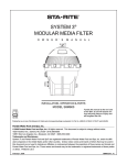
1
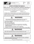
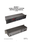
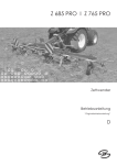
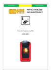
Manual:
Supersedes:
File:
Date:
BARD MANUFACTURING COMPANY
Bryan, Ohio 43506
Since 1914...Moving ahead, just as planned.
2100-279
Vol I, Tab 20
04-19-98
USER'S INFORMATION MANUAL
WAG-Series Combination Gas/Electric Wall-Mount™
We're pleased you've chosen our gas furnace to supply your heating needs. Please keep this manual in a
safe, yet readily available place. It contains important and useful information.
ATTENTION, INSTALLER: After installing furnace, give the user:
• User's Information Manual
• Installation Instructions
• Parts List
• Warranty Information
ATTENTION, USER! Your furnace installer should give you the above four important documents relating
to your furnace. Keep these as long as you do your furnace. Pass these documents on to later purchasers or
furnace users. If any of the four documents are missing or damaged, contact your installer or furnace
manufacturer for replacement. For efficient service, please give your furnace model and serial number,
from Section 1 or from your furnace rating plate.
WARNING
If the information in this manual is not followed exactly, a fire or explosion may
result causing property damage, personal injury or loss of life
• Do not store or use gasoline or other flammable vapors and liquids in the
vicinity of this or any other appliance.
• WHAT TO DO IF YOU SMELL GAS
• Do not try to light any appliance.
• Do not touch any electrical switch; do not use any phone in your building.
• Immediately call your gas supplier from a neighbor's phone. Follow the gas
supplier's instructions.
• If you cannot reach your gas supplier, call the fire department.
• Installation and service must be performed by a qualified installer or the gas
supplier.
WARNING
Read and follow all safety information in this manual, operating instructions and
furnace safety labels. Failure to follow safety precautions could result in damage,
injury or death.
IMPORTANT SAFETY NOTE: You must know how to turn off gas and electricity to furnace. Your
qualified installer, service agency or gas supplier can teach you to use controls and switches.
WARNING
Do not use this furnace if any part has been under water. Immediately call a qualified
service technician to inspect the furnace and to replace any part of the control system
and any gas control which has been underwater.
Thank you for reading these safety statements. Please read on so you will know
how to maintain your furnace for years of dependable service.
Contents
Section 1
Rating Plate Information ....................................... 1
Figures
Figure 1
Typical Gas Piping .............................. 4
Section 2
Important Safety Precautions ............................... 1
Figure 2
Step-by-Step Instructions
on Lighting Burners ............................. 6
Section 3
Understanding How Your Furnace Works ............ 3
Figure 3
Filter Locations ................................... 9
Figure 4
Location of Access Panels ................. 9
Figure 5
Pilot Flame Adjustment ..................... 10
Figure 6
Main Burner Flame Adjustment ......... 10
Figure 7
Start Up Procedures ......................... 10
Figure 8
Air Damper Positions ........................ 10
Section 4
Turning Off Furnace in an Emergency .................. 4
Section 5
Operating Your Furnace ....................................... 6
Section 6
Proper Maintenance of Your Furnace ................... 7
Section 7
Air Conditioning Start Up Procedure
Crankcase Heater .............................................. 10
Section 8
Fresh Air Damper Assembly .............................. 10
Section 9
Replacement Parts ............................................ 11
COPYRIGHT APRIL 1988
BARD MANUFACTURING COMPANY
BRYAN, OHIO USA 43506
SECTION 1 • RATING PLATE INFORMATION
Record the manufacturer’s name, unit model number and serial number below. These are your furnace rating plate.
Record installation date which is important for warranty purposes.
YOUR FURNACE INFORMATION
Furnace Type ___________________________________________________________________
Manufacturer’s Name _____________________________________________________________
Model Number __________________________________________________________________
Serial Number ___________________________________________________________________
Date Installed ___________________________________________________________________
Installer/Servicer _________________________________________________________________
Address ________________________________________________________________________
City/State/Zip Code _______________________________________________________________
Telephone Number ________________________________________________________
SECTION 2 • IMPORTANT SAFETY
PRECAUTIONS
2.A HAZARD ALERT SYMBOL
An explanation point surrounded by a triangle.
2.B SIGNAL WORDS
Years of safe, dependable service are assured when you
understand and follow all safety precautions.
Signal words “WARNING” and “CAUTION” alert
you to potential hazards.
“WARNING” indicates a potentially hazardous
situation which, if not avoided, could result in death or
serious injury.
“CAUTION” indicates a potentially hazardous
situation which, if not avoided, may result in minor or
moderate injury. It may also be used to alert against
unsafe practices. It can also be used to signal property
damage only potential.
2.B. SAFETY PRECAUTIONS
These are some of our most important safety
precautions; others are throughout this manual. Please
read and follow them.
2.1 GAS AND COMBUSTION PRODUCTS
WARNING
Any condition that will allow gas of combustion
products to enter furnace area can cause
nausea, asphyxiation or fire resulting in
damage, injury or death.
Natural gas and propane (LP) gas have characteristic
odors. When your furnace is operating correctly, you
should not smell any unfamiliar odor. Normally,
burning gas with air produces combustion products
which contain carbon dioxide, oxygen and water vapor.
Under abnormal conditions, combustion products and
contain aldehydes and carbon monoxide.
• Aldehydes have a strong pungent, acrid smell that
can cause nausea.
• Carbon monoxide is tasteless, colorless and odorless.
It can cause headaches, flu-like symptoms or
nausea. We refer to all these symptoms as nausea in
this manual. It can also cause death by
asphyxiation.
Manual 2100-279
Page 1
WARNING
WARNING
Any unfamiliar smell can alert you to presence
of gas or aldehydes. If you detect any
unfamiliar odor follow instruction in Section
4.B.1. Otherwise, nausea, asphyxiation or fire
could occur resulting in damage, injury or
death.
Do not operate furnace with blower door open
or removed. Do not alter furnace to allow
operation with blower door removed. Doing
either could allow combustion products to
circulate throughout the furnace area causing
nausea, asphyxiation or fire resulting in
damage, injury or death.
WARNING
WARNING
Do not block or cover combustion openings in
the furnace door or closet door. Blocking or
covering these openings could cause nausea,
asphyxiation or fire resulting in damage, injury
or death.
WARNING
Do not block or cover any openings from
outside the furnace area which supply
combustion and ventilation air to your furnace.
Keep insulation away form these openings.
Blocking or covering these openings could
cause nausea, asphyxiation or fire resulting in
damage, injury or death.
WARNING
A loud noise may mean faulty burner ignition.
If your furnace makes a loud noise, turn it off.
Follow instructions in Section 4.B.2. If you don’t
turn off your furnace, it could cause fire or an
explosion resulting in damage, injury or death.
WARNING
If your furnace is in an attic or other insulated
space, keep all insulating materials at least 12
inches away from its burner combustion air
openings. Block or covering these openings
could cause nausea, asphyxiation or fire
resulting in damage, injury or death. Examine
furnace area when the furnace is installed or
when insulation is added to that area.
Insulation materials may be combustible.
Manual 2100-279
Page 2
Front door must be in place during furnace
operation. Hot surfaces behind front door.
2.2
STORAGE AND USE OF FLAMMABLE,
CORROSIVE AND COMBUSTIBLE
PRODUCTS NEAR YOUR FURNACE
WARNING
Never store or use flammable liquids or vapors
near or on your furnace. These include
gasoline, kerosene, cigarette lighter fluid,
cleaning fluids, solvents, paint thinners or
painting compounds. Flammable vapors can
travel great distances before igniting.
WARNING
Never store or use anything near or on your
furnace that can produce vapors that are
corrosive to gas-fired furnaces. Vapors from
products containing chlorines, fluorines,
bromines and iodines can cause vent system or
heat exchanger failure. Examples of such
products are spray or aerosol containers,
detergents, bleaches, cat litter, waxes,
adhesives, solvents and other cleaning
compounds. Vent system or heat exchanger
failure could cause nausea, asphyxiation or fire
resulting in damage, injury or death.
WARNING
Never store anything combustible near or on
your furnace. These include brooms,
dustmops, vacuum cleaners, other cleaning
tools or items, plastic or plaxtic containers,
paper bags or other paper products. A fire
could occur resulting in damage, injury or
death.
2.3. ALTERATION OF FURNACE CONTROLS
WARNING
Do not alter any gas or electrical controls (gas
control, pilot or safety controls) in any manner.
Altering them could cause furnace to operate
unsafely resulting in damage, injury or death.
SECTION 3 • UNDERSTANDING HOW
YOUR FURNACE WORKS
Your installer should have given you a detailed explanation
of how the furnace operates. Shown below are the basic
operation characteristics and sequence of operation. If you
have any questions consult your installer and/or service
agency.
* * IMPORTANT * *
There are many types of thermostats
compatible with this furnace. Make sure you
understand the specific type installed. Ask
installer for detailed explanation, and retain
thermostat instruction manual for reference.
This furnace is equipped with a vent shut-off system which
monitors the combustion air into the burners by means of a
pressure sensing device. When the vent becomes blocked,
this device turns off the gas valve circuit to prevent flue
products from entering the structure. In the event that this
occurs, shut off furnace and contact a qualified service
agency.
3.1
BASIC OPERATION – HEATING CYCLE
This furnace is operated by an Electronic Blower Control
(EBC) and a gas control system which controls all functions
of the furnace.
On a call for heat from the thermostat, the EBC first turns on
the inducer motor. The pressure switch then closes
signaling the ignition control to proceed with ignition
function.
The ignition system consists of an intermittent pilot with a
hot surface igniter to light pilot burner, senses flame, and
then main gas valve opens with pilot flame lighting main
burners.
There is a 60 second delay after main burner is on until the
comfort air blower starts on heating (low) speed. After the
thermostat is satisfied, the burners will go off as gas
valve closes. The inducer will continue to run for 5
seconds, and the comfort air blower will continue to run for
two minutes.
3.2
BASIC OPERATION – COOLING CYCLE
On a call for cool the compressor and condenser fan will
start immediately, and the comfort air blower will start 6
seconds later on cooling (high) speed. When the thermostat
is satisfied the compressor and condenser fan will stop, and
the comfort air blower will continue to operate for 60
seconds.
3.2.1 COMPRESSOR LOCKOUT (CANADIAN
UNITS ONLY)
The units built for Canadian use are equipped with high and
low pressure controls. These controls protect the
compressor from extreme conditions such as high refrigerant
pressure or a loss of charge. When this happens the
compressor is held off line by a lock out relay. To reset the
lock out relay, the thermostat must be set to the “OFF”
position and then returned to the normal operating position.
The compressor is now allowed to function. If the
compressor continues to lock out, service personnel should
be called to check the unit.
3.3
MANUAL FAN (CONTINUOUS AIRFLOW)
OPERATION
If wall thermostat is set to MANUAL (ON) position to
operate comfort air blower continuously to provide air
circulation throughout the building, the blower will
operate on the heating speed rather than the cooling as is
typical with most systems. This permits the air to
circulate as desired but helps keep the operating noise
level down as well as conserving energy.
During a call for cooling, the blower automatically shifts up
to cooling speed, and remains there until 60 seconds
after thermostat is satisfied then drops back to heating
speed.
Manual 2100-279
Page 3
SECTION 4 • TURNING OFF FURNACE IN
AN EMERGENCY
FIGURE 1 – TYPICAL GAS PIPING
WARNING
Have a qualified installer, service agency or gas
supplier teach you location and operation of
gas and electrical shutoff devices. Ask them
any questions you have about this section. If
you don’t turn off your furnace in an emergency
damage, injury or death could result.
In an emergency you MUST know how to turn off gas and
electricity. Find out how BEFORE THE EMERGENCY.
WARNING
Should overheating occur or the gas supply fail
to shut off, shut off the manual gas valve to the
furnace before shutting off the electrical supply.
Failure to do so can cause a fire or explosion
which could result in damage, injury of death.
4.A GAS AND ELECTRICAL SHUTOFF DEVICES
1. GAS SHUTOFF DEVICES
In an emergency, you may not be able to reach all
the gas shutoff devices. You must know how to
turn off gas using any one of the three manual types:
a. Manual Shutoff Switch on Gas Control
Gas control location is behind the middle
access panel on the right side. See Lighting and
Shutdown Instructions in Section 5 for more
informantion.
To turn gas control furnace switch OFF, switch
it to “OFF” position. Use this same procedure
when you leave a vacation home vacant and do
not want the furnace to operate.
b. Manual In-Line Shutoff Valve in Gas Supply
Line
This valve is next to furnace. Figure 1 shows a
typical installation.
Normally, gas is ON when you turn the shutoff
valve handle parallel to gas pipe. Gas is OFF
when you turn handle 90° from gas pipe.
Manual 2100-279
Page 4
c. Manual Shutoff Valve at Natural Gas Meter
or Propane (LP) Gas Tank
Normally, natural gas is ON when you turn
shutoff parallel to gas pipe. Gas is OFF when
you turn shutoff 90° from gas pipe. Some valves
require a wrench or other tools.
2. ELECTRICAL SHUTOFF DEVICES
In an emergency, you may not be able to reach both
of your electrical shutoff devices. Therefore, you
must know how to turn off electricity using either
one of them. Here are two types of electrical shutoff
devices:
a. There should be an electrical shutoff device
located on or immediately adjacent to the
furnace.
b. There should be a separate circuit breaker or
fuse serving only the furnace located in the main
circuit breaker or fuse panel. Know its location
and make sure this device is clearly identified.
4.B POSSIBLE EMERGENCIES AND
RECOMMENDED ACTIONS
WARNING
If gas or electricity is off due to an
emergency, only a qualified installer, service
agency or gas supplier should turn it back on.
Doing it yourself could result in damage, injury
or death.
c. Your furnace should now be off. If it is, call
your service technician or gas supplier.
d. If your furnace continuers to run, leave your
home or building immediately. Call your gas
supplier or fire department from a neighbor’s
phone for help.
3. Possible Emergency: Your thermostat is set above
room temperature. The blower is on but the air
coming from your room registers is hot, then cold,
then hot, then cold in a continuing cycle. This
condition indicates lack of airflow through furnace.
ACTION:
1. Possible Emergency: Smelling gas or other
unfamiliar smell; or not knowing what may be
wrong or that to do about it.
ACTION: For your safety –
a. Leave your house or building immediately.
b. Go to a neighbor’s or another building.
c. Use their telephone.
d. Call your gas supplier. Tell them you smell gas
and give them your name and address.
a. Make sure air filter is clean and installed
correctly.
b. Check that registers and return air grilles are
open and unobstructed.
c. If condition continues, call your local qualified
service technician or gas supplier.
4. Possible Emergency: While furnace is operating,
you smell unfamiliar odors that go away when
furnace is off.
e. If you cannot reach gas supplier, call fire
department.
WARNING
Three important things not to do –
1. Don’t try to light any gas appliances.
2. Don’t touch any electrical switches
3. Don’t use the telephone in your house or
building.
Any of the above may cause a spark which
could cause a fire or explosion resulting in
damage, personal injury or death.
2. Possible Emergency: Your thermostat is set below
room temperature; yet even though the blower is on,
the air coming from your room registers continually
gets hotter.
ACTION:
a. Turn room thermostat to its lowest or OFF
setting.
b. If you can do so safely, turn gas off. Use
manual shutoff valve at gas meter or on propane
(LP) gas tank. You may need a wrench or tools.
If you can safely turn off electricity at the main
circuit panel, do so. If you cannot do these
things safely, leave your home or building
immediately. Call your gas supplier or fire
department from a neighbor’s phone for help.
WARNING
Unfamiliar odors may mean gas or aldehydes
are present which could result in damage, injury
or death.
ACTION:
a. Turn thermostat to its lowest or OFF setting.
b. Move gas valve control level to OFF.
c. If blower is not operating, immediately turn of
electricity to furnace using shutoff device near
furnace or at main circuit panel.
d. If blower is operating, wait five minutes for
furnace to cool down and then turn off electricity
to furnace using shutoff device near furnace or at
main circuit panel.
e. Call your local qualified service technician or
gas supplier.
5. Possible Emergency: Main electrical circuit
breaker for furnace cannot be reset without tripping
again or new fuses continue to blow.
ACTION:
a. Move gas valve control level to OFF.
b. Call your local qualified service technician or
gas supplier.
Manual 2100-279
Page 5
SECTION 5 • OPERATING YOUR
FURNACE
After reading the Safety Information and Precautions follow
Operating Instructions on front door of furnace and
instructions repeated here.
WARNING
If you do not follow these instructions exactly
a fire or explosion could occur resulting in
damage, injury or death.
WARNING
Never use tools to move gas control switch.
Only use your hand. If gas control switch will
not move by hand, do not force it or try to repair
it. Call a qualified installer, service agency or
gas supplier. Forcing switch can cause gas to
leak which could result in fire or explosion.
Properly operating your furnace requires certain abilities,
mechanical skills and tools. If you are uncertain about your
abilities or if you lack proper skills or tools, do not proceed.
Instead, contact a qualified installer, service agency or gas
supplier.
An automatic ignition device lights the burners. Do not try
to light manually. See Figure 2 for step by step instructions.
FIGURE 2
Manual 2100-279
Page 6
SECTION 6 • PROPER MAINTENANCE OF
YOUR FURNACE
6.D KEEP AIR FILTER(S) CLEAN
As a user, your personal responsibility is to keep air
filter(s) clean.
You need special abilities, mechanical skills and tools to
maintain your furnace properly. If you are uncertain about
your abilities or if you lack proper skills or tools, do not try
to maintain or repair you furnace yourself. Instead, contact a
qualified installer, service agency or gas supplier.
CAUTION
A dirty air filter(s) reduces system efficiency
and can cause erratic control performance.
These could result in damage to blower motor
or heat exchanger.
6.A IF YOU SMELL GAS OR ANY UNFAMILIAR
SMELL WHILE WORKING ON YOUR
FURNACE:
1. Do not try to light main burners.
2. Do not touch or turn on any electrical switch.
1. During the first four weeks after your furnace is
installed, inspect your air filter(s) for dirt every
week. Then check the filters monthly and clean as
necessary.
3. Do not use any phone in your building.
4. Immediately call your gas supplier from a
neighbor’s phone. Follow gas supplier’s
instructions.
2. If the filter(s) is of a washable type, clean filter(s)
according to the manufacturer’s specifications.
5. If you cannot reach your gas supplier, call fire
department.
WARNING
6.B LUBRICATION REQUIREMENTS
The main blower motor and the induced draft blower
motor are permanently lubricated, and no
maintenance is required.
After cleaning or changing filter(s), filter access
cover(s) must be replaced. Failure to do so
could cause nausea, asphyxiation, or fire
resulting in damage, injury or death.
6.C MAKE SURE AIR FILTER(S) IS IN PLACE
Ask your installer, local qualified service technician
or gas supplier to make sure your filter(s) is in place
properly. Become familiar with its location and
procedures for removing, cleaning and replacing it.
6.E DO NOT OBSTRUCT DUCT WORK
For proper operation, keep registers and return air
grilles open. Do not cover or block them with rugs,
carpets, drapes or furniture.
Recommended filter sizes are shown below.
6.F
MAIN SYSTEM FILTER: 20 X 30 X 1
Fiberglass disposable
FRESH AIR FILTER:
4 x 26 x 1/2
Washable
See Figure 3 for filter locations.
WARNING
Operating furnace without clean air filter(s) can
damage blower motor, heat exchanger or air
conditioning system components. This can
cause system failure which could result in
damage or injury.
HAVE YOUR FURNACE CHECKED
ANNUALLY
The furnace, vent terminal, and the combustion air
intake hood should be inspected yearly by a
qualified service agency, generally prior to the
heating season. Detailed procedures for this
inspection are contained in the instructions booklet
and should be handled by the qualified service
agency only.
A general inspection of the furnace, the furnace area
and the vent terminal should be conducted on a
regular basis by the owner/occupant. This review
should include:
1. Make sure the furnace always has the minimum
clearance as detailed on the furnace rating
plate. Special attention must be given to these
items if any remodeling is done.
2. Make sure the vent terminal is in place and
is physically sound.
Manual 2100-279
Page 7
3. Reviewing that the return air duct connection(s)
is physically sound, is sealed to the furnace
casing.
4. The physical support of the furnace is sound
without sagging, cracks, gaps, etc. around the
unit so as to provide a seal between the unit
and the structure.
5. Inspect for any obvious signs of deterioration of
the furnace.
6. Periodic examinations of the vent terminal
should also be conducted by the owner on a
regular basis, preferably every monthly but at
least every two months during the heating
season.
7. Check the entire vent terminal for any blockage.
If any debris is present remove it.
6.G THE FOLLOWING PROCEDURE SHOULD
BE FOLLOWED FOR THE PERIODIC
INSPECTION AS CONDUCTED BY THE
OWNER/OCCUPANT.
1. Set the wall thermostat to the OFF position or
lower the set point lever to a temperature will
below the existing room temperature. Shut off
electric power to the furnace. A switch should
be mounted either on the outside of the furnace
or adjacent to the furnace for this purpose.
2. Remove the burner access door. See Figure 4.
3. Use flashlight or trouble light to observe the
burner compartment and burners. There should
be very minimal scaling or sooting in this area.
Some loose debris may have fallen down on to
the floor of the heat exchanger form the tube
passageways, and this may be vacuumed out.
Also observe the sides of the heat exchanger
tubes for “hot spots” due to improper burner
alignment or overfiring and give particular
attention to any area where it looks like there
may be any deterioration from corrosion or
rusting. Observe for any corrosion on the
burners themselves. Should anything appear
questionable, contact your service agency.
Manual 2100-279
Page 8
4. Inspect the vent terminal, observing for any
debris from weather, birds, and the like. Clean
if necessary. Also check the small cover
assembly on Induced Draft Blower Door to make
sure it is clear. See Figure 4.
WARNING
Leakage of products of combustion into the
living area may result in asphyxiation resulting in
injury or death
5. Restore the electrical power to the furnace by
turning the switch back on. Adjust the
thermostat to call for heating operation.
6. Observe both the pilot flame and main burners
flames, and compare to Figures 5 and 6
respectively. The main burners should be mostly
“blue” with possibly a little orange (not yellow)
at the tips of the flames. The flames should be
in the center of the heat exchanger compartments
and impinging on the heat exchanger surfaces.
7. Observe the flames until the blower starts (there
is a normal delay 60 second period until the heat
exchanger warms up). There should be no
change in the size or shape of the flame. If there
is any wavering or blowing of the flame on the
blower start-up, it is an indication of a possible
leak in the heat exchanger. Turn off the gas
valve in the gas line leading to the furnace, and
then the main electrical switch to the furnace
and call your service agency.
8. Replace the burner access door.
FIGURE 3
MIS-058
FIGURE 4
MIS-059
Manual 2100-279
Page 9
FIGURE 5
FIGURE 6
FLAME SHOULD
ENGULF SENSOR
GROUND
STRAP
IGNITER
HEAT
EXCHANGER
SECTION
SENSOR
OUTER
CONE
INNER
CONE
NO LIFTING AWAY
FROM BURNER
PORTS
MIS-1067
SECTION 7 • AIR CONDITIONING START
UP PROCEDURE CRANKCASE HEATERS
SECTION 8 • FRESH AIR DAMPER
ASSEMBLY
Single and three phase models have an insertion well-type
heater located in the lower section of the compressor
housing. This is a self-regulating type heater that draws
only enough power to maintain the compressor at a safe
temperature.
The fresh air damper assembly permits outside fresh air to
be introduced to the building whenever the main unit
comfort air blower is operating. The damper blade may be
set to one of four positions: 1) full open, 2) 50% open, 3)
full closed, or 4) automatic (barometric) operation. In the
latter set-up the damper blade will open and close as the
main comfort air blower cycles on and off. Reference Figure
8 for details on damper positions.
Some form of crankcase heat is essential to prevent liquid
refrigerant from migrating to the compressor, causing oil
pump out on compressor start-up and possible valve failure
due to compressing a liquid.
The decal in Figure 7 is affixed to all outdoor units detailing
start-up procedures. This is very important. Please read
carefully.
FIGURE 7
IMPORTANT
There is also a cleanable filter installed at the bottom
opening of the fresh air damper that requires periodic
cleaning. The cleaning interval will be dependent upon
frequency of unit operation and local air conditions. See
Figure 3 for Fresh Air Damper and filter locations.
FIGURE 8
These procedures must be followed at
initial start-up and at any time power has
been removed for 12 hours or longer.
To prevent compressor damage which
may result from the presence of liquid
refrigerant in the compressor crankcase.
1. Make certain the room thermostat is in
the “off” position (the compressor is not
to operate).
2. Apply power by closing the system
disconnect switch. This energizes the
compressor heater which evaporates the
liquid refrigerant in the crankcase.
3. Allow 4 hours or 60 minutes per pound
of refrigerant in the system as noted on
the unit rating plate, whichever is greater.
4. After properly elapsed time, the
thermostat may be set to operate the
compressor.
5. Except as required for safety while
servicing—Do not open system
disconnect switch.
7961-061
Manual 2100-279
Page 10
FULL OPEN
NORMAL BAROMETRIC
POSITION
50% OPEN FIXED POSITION. (2)
ADDTIONAL CANOE CLIPS ARE
TAPED TO THE INSIDE OF
DAMPER ASSEMBLY
TOTALLY CLOSED
POSITON
MIS-957
SECTION 9 • REPLACEMENT PARTS
Replacement parts for the gas/electric units are available
through local distributors.
A replacement parts list manual is supplied with each unit.
When ordering parts or making inquiries pertaining to any
of the units covered by these instructions, it is very
important to always supply the COMPLETE model number
and serial number of the unit. This is necessary to assure
that the correct parts (or an approved alternate part) are
issued to the service agency.
Manual 2100-279
Page 11