1
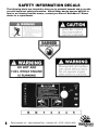
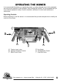
Dixon Industries, Inc. • Airport Industrial Park • Coffeyville, KS • 67337
620.251.2000 • www.dixon-ztr.com
Parts & Owner’s Manual
36” & 48” Commercial
Belt-Drive Mowers
Congratulations on the purchase of your new
Dixon mower.
Before any warranty service can be authorized you
must register this product with the manufacturer.
© Dixon Industries Inc.
Dixon Industries, Inc. • Airport Industrial Park • Coffeyville, KS • 67337
620.251.2000 • www.dixon-ztr.com
Owner’s Manual For Dixon 36” & 48”
Commercial Belt-Drive Mowers
TABLE OF CONTENTS
About This Manual . . . . . . . . . . . . . . . . . . . . . . . . . . . . . . . . . . . . . . . . . . . . . . . . . . . . . . . . . . . . . . . . . . . . . . .4
Warranty . . . . . . . . . . . . . . . . . . . . . . . . . . . . . . . . . . . . . . . . . . . . . . . . . . . . . . . . . . . . . . . . . . . . . . . . . . . . . . .5
Safety Information
Training . . . . . . . . . . . . . . . . . . . . . . . . . . . . . . . . . . . . . . . . . . . . . . . . . . . . . . . . . . . . . . . . . . . . . . . . . .6
Before Use of Equipment . . . . . . . . . . . . . . . . . . . . . . . . . . . . . . . . . . . . . . . . . . . . . . . . . . . . . . . . . . . .6
Operation Of the Equipment . . . . . . . . . . . . . . . . . . . . . . . . . . . . . . . . . . . . . . . . . . . . . . . . . . . . . . . . . .7
Safety Information Decals . . . . . . . . . . . . . . . . . . . . . . . . . . . . . . . . . . . . . . . . . . . . . . . . . . . . . . . . . . .8
Operating The Mower
Operating Controls . . . . . . . . . . . . . . . . . . . . . . . . . . . . . . . . . . . . . . . . . . . . . . . . . . . . . . . . . . . . . . . . .9
Starting the Engine . . . . . . . . . . . . . . . . . . . . . . . . . . . . . . . . . . . . . . . . . . . . . . . . . . . . . . . . . . . . . . . .10
Going Forward . . . . . . . . . . . . . . . . . . . . . . . . . . . . . . . . . . . . . . . . . . . . . . . . . . . . . . . . . . . . . . . . . . .10
Turning The Mower . . . . . . . . . . . . . . . . . . . . . . . . . . . . . . . . . . . . . . . . . . . . . . . . . . . . . . . . . . . . . . . .11
Stopping The Mower . . . . . . . . . . . . . . . . . . . . . . . . . . . . . . . . . . . . . . . . . . . . . . . . . . . . . . . . . . . . . . .11
Going In Reverse . . . . . . . . . . . . . . . . . . . . . . . . . . . . . . . . . . . . . . . . . . . . . . . . . . . . . . . . . . . . . . . . .11
Mowing . . . . . . . . . . . . . . . . . . . . . . . . . . . . . . . . . . . . . . . . . . . . . . . . . . . . . . . . . . . . . . . . . . . . . . . . .11
Height Of Cut
Measuring . . . . . . . . . . . . . . . . . . . . . . . . . . . . . . . . . . . . . . . . . . . . . . . . . . . . . . . . . . . . . . . . . .12
Adjusting Blades . . . . . . . . . . . . . . . . . . . . . . . . . . . . . . . . . . . . . . . . . . . . . . . . . . . . . . . . . . . . .12
Adjusting Front Wheels . . . . . . . . . . . . . . . . . . . . . . . . . . . . . . . . . . . . . . . . . . . . . . . . . . . . . . . .12
Service And Maintenance Of The Mower
Maintenance Schedule . . . . . . . . . . . . . . . . . . . . . . . . . . . . . . . . . . . . . . . . . . . . . . . . . . . . . . . . . . . . .14
Fuel . . . . . . . . . . . . . . . . . . . . . . . . . . . . . . . . . . . . . . . . . . . . . . . . . . . . . . . . . . . . . . . . . . . . . . . . . . .15
Engine Oil . . . . . . . . . . . . . . . . . . . . . . . . . . . . . . . . . . . . . . . . . . . . . . . . . . . . . . . . . . . . . . . . . . . . . . .15
Air Filter . . . . . . . . . . . . . . . . . . . . . . . . . . . . . . . . . . . . . . . . . . . . . . . . . . . . . . . . . . . . . . . . . . . . . . . .15
Tire Pressure . . . . . . . . . . . . . . . . . . . . . . . . . . . . . . . . . . . . . . . . . . . . . . . . . . . . . . . . . . . . . . . . . . . .15
Blades . . . . . . . . . . . . . . . . . . . . . . . . . . . . . . . . . . . . . . . . . . . . . . . . . . . . . . . . . . . . . . . . . . . . . . . . . .15
Cleaning The Mower . . . . . . . . . . . . . . . . . . . . . . . . . . . . . . . . . . . . . . . . . . . . . . . . . . . . . . . . . . . . . .15
Lubrication Points . . . . . . . . . . . . . . . . . . . . . . . . . . . . . . . . . . . . . . . . . . . . . . . . . . . . . . . . . . . . . . . . .16
Service Adjustments
Wheel Brake Adjustments . . . . . . . . . . . . . . . . . . . . . . . . . . . . . . . . . . . . . . . . . . . . . . . . . . . . . . . . . .17
Wheel Brakes . . . . . . . . . . . . . . . . . . . . . . . . . . . . . . . . . . . . . . . . . . . . . . . . . . . . . . . . . . . . . . . . . . . .17
Engine To Blade Belt . . . . . . . . . . . . . . . . . . . . . . . . . . . . . . . . . . . . . . . . . . . . . . . . . . . . . . . . . . . . . .18
Blade To Blade Belt . . . . . . . . . . . . . . . . . . . . . . . . . . . . . . . . . . . . . . . . . . . . . . . . . . . . . . . . . . . . . . .19
Engine To Transmission Belt . . . . . . . . . . . . . . . . . . . . . . . . . . . . . . . . . . . . . . . . . . . . . . . . . . . . . . . .19
Safety Interlock System . . . . . . . . . . . . . . . . . . . . . . . . . . . . . . . . . . . . . . . . . . . . . . . . . . . . . . . . . . . .19
Troubleshooting Guide . . . . . . . . . . . . . . . . . . . . . . . . . . . . . . . . . . . . . . . . . . . . . . . . . . . . . . . . . . . . . . . . . . .20
NOTES
_______________________________________________
_______________________________________________
_______________________________________________
_______________________________________________
_______________________________________________
_______________________________________________
_______________________________________________
_______________________________________________
_______________________________________________
_______________________________________________
_______________________________________________
_______________________________________________
_______________________________________________
_______________________________________________
_______________________________________________
_______________________________________________
_______________________________________________
_______________________________________________
Dixon Industries, Inc. • Airport Industrial Park • Coffeyville, KS • 67337 • 620-251-2000
3
About This Manual
This owner’s manual is considered a permanent part of the mower. It must be available to all of
the operators and/or person(s) servicing the mower. Should the mower be resold, this manual
must remain with the mower.
All information, illustrations, and specifications contained in this manual were in effect at the
time of publication. Dixon Industries, Inc. reserves the right to change, modify, and/or discontinue specifications and/or design without notice. If there is a change that has been made to
your mower which is not shown or reflected in this manual, please see your authorized Bradley
Mower dealer before operating and/or servicing the equipment.
Congratulations on the purchase of your new Dixon commercial mower. We at Dixon
Industries, Inc. are confident that this mower will provide you with years of excellent performance,
durability, and trouble free service when operated and maintained as directed in this manual.
Should you ever have any questions regarding the operation, maintenance, or safety of your
mower, please contact your authorized Dixon Mower dealer who has been specially trained on
operation and service of Dixon Mowers.
A space has been provided below to record information about your new Dixon Mower. Please
take time to record such information for future reference, especially when you contact an
authorized Dixon Mower dealer with questions.
Date Purchased:
____________________________________________________
Model Number:
____________________________________________________
Serial Number:
____________________________________________________
Purchased From: ____________________________________________________
____________________________________________________
4
Dixon Industries, Inc. • Airport Industrial Park • Coffeyville, KS • 67337 • 620-251-2000
DIXON® LIMITED WARRANTY POLICY
WalkAbout™ Mowers
DIXON® WALKABOUT™ MOWERS ARE WARRANTED AGAINST DEFECTS IN MATERIALS AND WORKMANSHIP AND PROVIDES FOR REPLACEMENT OR REPAIR OF PARTS INCLUDING LABOR COSTS.
THIS WARRANTY IS SUBJECT TO THE FOLLOWING CONDITIONS AND LIMITATIONS.
1. Dixon® WalkAbout™ mowers are warranted for one (1) year from date of purchase for residential or
commercial use.
2. Warranty applies only to original retail purchase of new and unused mowers and accessories.
3. All Dixon® warranty must be accomplished by authorized Dixon® dealers and in accordance with
Dixon® warranty policy and allowances. All warranty claims must be approved by Dixon Industries, Inc.
4. Warranty does not apply to damage in transit or incidents of misuse, negligence, accidents, or
alteration. The use of parts or components other than those supplied by Dixon Industries VOIDS ALL
WARRANTY.
5. The following items are not covered by this warranty policy:
(a) Pick up and delivery charges for transportation of mower to and from an authorized Dixon® dealer’s
place of business.
(b) Routine maintenance or adjustments.
(c) Belts, blades, tilters or tires.
(d) Engines - all engines used on Dixon® WalkAbout™ mowers are warranted by each individual
engine manufacturer.
(e) Transmission - All transmissions used on Dixon® WalkAbout™ mowers are warranted by the
transmission manufacturer.
(f) Any costs or expense of providing substitute equipment while repair work is being performed on a
warranted mower.
6. There is no other express warranty. Implied warranties, including those of merchantability and fitness
for a particular purpose are limited to the same duration if the express warranty and to the extent
permitted by law any and all implied warranties are excluded. Liabilities for consequential damages
under any and all warranties are excluded.
Dixon Industries, Inc. • Airport Industrial Park • Coffeyville, KS • 67337 • 620-251-2000
5
SAFETY INFORMATION
Read This Manual Carefully And Thoroughly Before Operating The Mower!
Training
1. Carefully and thoroughly read the owner’s manual. Allow adequate time to fully understand the controls and
operation of the equipment.
2. Never allow anyone to operate the mower that has not read and fully understood the owner’s manual.
3. Do not carry passengers. Avoid mowing while people, especially children and pets are nearby, since rotating
blades can throw rocks and other items with enough force to cause serious injury.
Before Use of Equipment
Operator:
Wear protective clothing while mowing. Long trousers and safety glasses will help reduce the risk of injury from
thrown objects. It is recommended that steel toe shoes with aggressive soles or some other type of substantial
footwear be worn to help protect your feet and maintain traction on slopes or uneven ground. Always wear hearing protection.
Mowing Area:
Thoroughly inspect the area where the equipment is to be used. Look for items such as stones, sticks, wire and
other foreign objects. When struck by the mower, these and other objects my become projectiles that could lead
to serous injury and/or death.
Mower:
For your safety and the long life of your mower, always inspect the mower before each use. Before inspection,
make sure it is on a flat and level surface, the blades are disengaged, the ignition switch off with the key
removed, and the spark plug wire is off of the spark plug(s) and hidden so that accidental contact can not be
made,
General Condition:
·
Walk around the mower looking for any fluid spills or leaks on or underneath the mower. Remove any
and all excessive debris, dirt, and/or fluids.
·
Look for signs of damage or excessive wear. Check the tightness of all nuts, bolts, pins, and screws.
Tighten any that may be loose and replace any that may have been lost during use.
·
Be sure the safety interlock controls are operating properly so that the engine can not be started unless
the ground speed control lever is in neutral and the blades disengaged.
·
·
·
·
6
Check the mower blades for any damage or abnormal wear and replace in sets so that they are balanced.
Check the tire pressure on all four tires. See page 15 for details.
Check all belts for proper wear and correct tension. See pages 17-19 for details.
Check engine oil and air filters as recommended in the engine manufacturers’ operators manual.
Dixon Industries, Inc. • Airport Industrial Park • Coffeyville, KS • 67337 • 620-251-2000
Operation of Equipment
!
DANGER: GASOLINE IS HIGHLY FLAMMABLE AND EXPLOSIVE. DO NOT ADD FUEL WHILE THE
ENGINE IS RUNNING OR IS HOT. KEEP OPEN FLAMES, SPARKS, AND HEAT AWAY FROM THE
FUEL AND STORE FUEL IN CONTAINERS SPECIFICALLY DESIGNED FOR THAT PURPOSE. ADD
FUEL OUTDOORS ONLY AND IF THE FUEL IS SPILLED, DO NOT START THE ENGINE. MANUALLY
PUSH THE MOWER AWAY FROM THE SPILL AND IMMEDIATELY WIPE UP.
Do not operate the engine in a confined space where dangerous carbon monoxide fumes can collect.
Carbon monoxide is odorless, tasteless, and can be fatal.
Mow only in daylight.
Do not park on hills without the use of wheel blocks.
Make sure the mower is in neutral and the blades are disengaged before attempting to start the engine.
Do not stop or start suddenly when going uphill. Never use riding attachments on slopes since there is an
increase risk that they might roll over.
Avoid steep slopes and use extreme caution when changing directions or speed when operating on a slope.
Be extremely careful when operating on a slope or when the grass is damp or wet. Reduced traction could
cause sliding. Never mow by pulling the mower back towards you...you might slip.
Watch for traffic when crossing surfaces other than grass. (i.e. transporting,) loading a trailer or vehicle, or
when the mower is not in use.
Never operate the mower with defective guards, shields, or without the safety devices securely mounted in
place.
Never direct discharge of material toward bystanders nor allow anyone near the mower while in operation.
Do not change the governor settings or over speed the engine.
Always stop the engine whenever you leave the mower, even for a moment.
To help reduce the risk of a fire hazard, keep the engine and the area around the engine free of grass,
leaves, or any other type of foreign material.
Beware of cutting edges. Always wear gloves for safety when performing blade maintenance activities.
Beware on multiple blades units since the rotation of one blade may cause the rotation of the other blade.
Do not store or operate the mower with the grass chute deflector in raised position. Serious injury could
occur.
Dixon Industries, Inc. • Airport Industrial Park • Coffeyville, KS • 67337 • 620-251-2000
7
SAFETY INFORMATION DECALS
The following labels are intended to alert you to potential hazards and to provide
you with important safety information. Should these decals become difficult to
read or are missing from the mower, contact your Dixon® WalkAbout™ Mower
dealer for a replacement.
8
Dixon Industries, Inc. • Airport Industrial Park • Coffeyville, KS • 67337 • 620-251-2000
OPERATING THE MOWER
It is recommended that before you operate the mower, you allow adequate time to fully understand
the controls and operation of the equipment. When reading this manual, it is recommended that you
do so with the equipment nearby for quick orientation, reference of controls and maintenance
adjustments.
Operating Controls
Before continuing to read the manual, it is recommended that you take adequate time to identify the
controls of the mower.
C
D
B
B
E
A
“A” Traction Lever Locks
“B” Operator Presence Controls
“C” Blade Control Lever
F
A
“D” Key Switch
“E” Throttle/Choke Control
“F” Gear Shift Lever
Dixon Industries, Inc. • Airport Industrial Park • Coffeyville, KS • 67337 • 620-251-2000
9
Starting The Engine:
!
DANGER: DO NOT OPERATE THE ENGINE IN A CONFINED SPACE
WHERE DANGEROUS CARBON MONOXIDE FUMES CAN COLLECT.
CARBON DIOXIDE IS ODORLESS, TASTELESS, AND CAN BE FATAL.
After going through the steps as discussed on pages (6) and (7), you
are now ready to start the engine. NOTE: THIS UNIT WAS SHIPPED
WITHOUT THE GAS, BE SURE TO ADD FRESH GAS AND TO DOUBLE CHECK THE OIL IN THE ENGINE BEFORE ATTEMPTING TO
START THE MOWER.
Figure 2
1. Make sure that the shut off valve, located at the bottom of the fuel tank
is in the “ON” position (figure 2).
2. Make sure that the traction control lever are in the neutral position(figure 3)
3. Make sure that the gear shift lever is in the neutral “N” position (figure 4)
4. Make sure that the blade control lever is in the “OFF” position. NOTE: The
safety interlock system will prevent the engine from being started if the
blade control lever is not in the “OFF” position and the gear shift lever is
not in the neutral “N” position.
5. Slide the engine speed control to the “
“ position, or to “CHOKE” if the
engine is cold.
6. Turn the key clockwise to the “RUN” position.
7. Slowly pull the start cord on the engine until just past compression. STOP!
Figure 3
Return the start cord and then pull firmly with a smooth, steady motion to
start the engine.
8. When the engine starts to run, slowly return the engine speed control out
of “CHOKE” to the desired engine speed.
Going Forward:
CAUTION Become totally familiar with the operation and characteristics of the mower before attempting to actually mow with it.
1. Making sure that the traction control levers are in the neutral position, push
down and hold the operator presence control lever “A” on the handle grips
with one hand (Figure 5).
Figure 4
2. With the other hand, move the gear shift lever to the desired speed. “1” is
slow and “5” is for transporting the mower between mowing areas (Figure
4). It is recommended that you start out in “1” and then increase your
ground speed to match the mowing conditions.
A
3. Release the traction control lever locks by squeezing up both traction control levers “C” only as much as needed while at the same time applying forward pressure in the traction control lever locks “B” with your thumbs.
4. Slowly and evenly, let both traction control levers down simultaneously and
the mower will start to go forward (Figure 5). NOTE: If the operator lets go
of both operator presence control levers while either the blade control lever
is in “ON”, and/or the gear shift control lever is out of the neutral position
the safety interlock system will stop the engine. To restart the mower, reset
all controls to the “OFF” position and neutral “N” positions.
10
B
C
Dixon Industries, Inc. • Airport Industrial Park • Coffeyville, KS • 67337 • 620-251-2000
Figure 5
Turning The Mower
To turn the mower in the direction you want to go, gently squeeze the side’s traction control lever (i.e. to go right,
squeeze the right traction control lever; to go left, squeeze the left traction control lever). The more a particular
traction control lever is squeezed, the sharper a turn the mower will make.
Stopping The Mower
To stop the mower, gently and evenly squeeze up on both of the traction control levers until the mower comes to a
complete stop. Then with your thumbs, push down on the traction lever locks until the levers are securely locked
in the neutral position. While still holding down with one hand the operator presence controls, move the gear shift
lever to the “N” position with the other hand. If the operator is leaving the operator’s position behind the mower for
any reason, disengage the blades, shut the engine off, and remove the key.
If you are leaving the operator’s position, try to park the mower on level ground. If it is not possible to do
such, be sure to block the wheels to prevent the mower from rolling away.
Using The Reverse Assist
1. Slowly and evenly squeeze up on both control levers until the mower comes to a complete stop and then with
your thumbs, push down on the traction lever locks until the levers are securely locked in the neutral position.
2. While still holding down the operator presence control with one hand, use the other and pull the blade control
lever to the “OFF” position.
3. Shift the gear shift lever to the reverse “R” position.
4. Release the traction control lever locks by squeezing by both traction control levers only as much as needed
while at the same time, applying forward pressure on the traction control lever locks with your thumbs.
5. Slowly and evenly, let both traction control levers down simultaneously and the mower will start to go in
reverse. Always use extreme caution when moving the mower backwards and never move the mower
downhill backwards.
6. To stop the mower, slowly and evenly squeeze up on both control levers until the mower comes to a complete
stop and then with your thumbs, push down on the traction lever locks until the levers are securely locked in
the neutral position and return the gear shift lever to neutral “N”.
Mowing
!
DANGER: THOROUGHLY INSPECT THE AREA WHERE THE EQUIPMENT IS TO BE USED. LOOK FOR
ITEMS SUCH AS STONES, STICKS, WIRE, AND OTHER FOREIGN OBJECTS. WHEN STRUCK BY THE
MOWER, THESE AND OTHER OBJECTS MAY BECOME PROJECTILES THAT COULD LEAD TO SERIOUS INJURY AND OR DEATH. CLEAR AREA OF ALL DEBRIS AND KEEP PEOPLE AND PETS AWAY.
!
DANGER: DO NOT OPERATE THE MOWER WITH DEFECTIVE GUARDS, SHIELDS, OR WITHOUT THE
SAFETY DEVICES SECURELY IN PLACE.
For the highest quality of cut and performance, always mow with the engine at full throttle. Quality of cut may
be determined by the ground speed and speed of the mower. Generally, the slower the mower travels across
the terrain, the better the cut.
With the mower at the beginning of the area to be mowed and traction control levers in the neutral position,
hold down with one hand the operator presence control.
With the other hand, slowly push the blade control lever forward to the “ON” position.
Move the gear shift lever to the desired speed. Always begin at a slow ground speed and increase only as the
condition of the terrain warrants.
Slowly and evenly, engage the traction control levers and begin mowing.
To stop mowing, slowly and evenly squeeze up on both traction control levers until the mower comes to a complete stop and then with your thumbs, push down on the traction lever locks until the levers are securely locked
in the neutral position. Return the gear shift lever to the neutral “N” position.
Pull the blade control lever back to the “OFF” position.
Dixon Industries, Inc. • Airport Industrial Park • Coffeyville, KS • 67337 • 620-251-2000
11
Changing The Height Of Cut:
!
DANGER: BEFORE MAKING ANY ADJUSTMENTS AND/OR SERVICING YOUR MOWER, MAKE SURE
THE MOWER IS ON LEVEL GROUND, BLADES DISENGAGED, KEYS REMOVED, AND THE ENGINE OFF
WITH THE SPARK PLUG WIRE(S) REMOVED FROM THE SPARK PLUGS(S) TO PREVENT ACCIDENTAL
CONTACT.
When your Dixon walkabout mower is shipped from the factory, the mowing height is set at 2-1/2”. The mowing
height may be raised or lowered using a combination of front wheel spacers and blade bolt assembly spacers.
It is recommended that you first set your height of cut to the highest level using the blade spacers and then
lower the height of cut using the front wheel spacers.
Measuring The Height Of Cut:
!
DANGER: BEFORE MAKING ANY ADJUSTMENTS AND/OR SERVICING YOUR MOWER, MAKE SURE
THE MOWER IS ON LEVEL GROUND, BLADES DISENGAGED, KEYS REMOVED, AND THE ENGINE OFF
WITH THE SPARK PLUG WIRE(S) REMOVED FROM THE SPARK PLUGS(S) TO PREVENT ACCIDENTAL
CONTACT.
CAUTION Beware of the cutting edges on the blades. The rotation of one blade may cause the other
blade(s) to rotate. Always wear work gloves when handling blades.
1. Park the mower on level ground.
2. With the blade control lever in the “OFF” position, the engine off with the key removed, and the spark
plug wire (s) removed from the spark plug(s), reach through the discharge chute and slowly rotate the blade
so that the length of the blade is going from the front of the mower towards the rear.
3. Using a tape measure or small ruler, measure the distance from the front tip of the blade’s cutting edge to the
ground. As a general rule, if measuring the cutting height on a hard surface such as concrete, the mower will
usually mow about 1/4” lower in grass due to the weight of the machine.
Removing And Adjusting The Blades:
1.
2.
3.
4.
5.
6.
7.
CAUTION Beware of the cutting edges on the blades. The rotation of one blade may cause the other
blade(s) to rotate. Always wear work gloves when handling blades.
Park the mower on level ground and block the rear wheels to prevent accidental rollback.
Raise the front end of the mower using a jackstand
Using two (2) 15/16” box end wrenches, use one wrench to loosen nut “A” while holding blade bolt “C” with the
other wrench (Figure 6).
Slide the blade bolt down through the mower deck and out.
To raise the blades to the height desired, remove the appropriate amount of spacers from the blade bolt.
Example: If the height of cut needs to be raised 1/2”, move two (2) of the 1/4” spacers “B” on each blade from
underneath the mower (Figure 6) to the top of the mower (Figure 7).
Reinsert the blade bolt through the cutting deck.
Install the blade spacers that were removed, back onto the blade bolt followed by the nut and tighten (Figure 6).
IMPORTANT: The amount of spacers should always be the same on each blade bolt. Never put the spacers
below the blade.
Adjusting The Front Wheels: (refer to Figure 8)
1.
2.
3.
4.
5.
6.
7.
12
Raise and support the front of the mower with a jackstand.
While supporting the front wheel with one hand, remove the flip pin from the wheel shaft.
Remove the wheel from the front wheel support arm being careful not to loose the spacers.
Remove the amount of spacers desired to lower the height of cut.
Reinsert the wheel through the support arm.
Reinstall the spacers on the top that were removed from the bottom and then secure with the flip pin.
To raise the height, repeat steps 1-3, but take the spacers from the top of the wheel support arm, and put
them on the bottom.
Dixon Industries, Inc. • Airport Industrial Park • Coffeyville, KS • 67337 • 620-251-2000
Figure 6
Figure 7
Figure 8
Dixon Industries, Inc. • Airport Industrial Park • Coffeyville, KS • 67337 • 620-251-2000
13
GENERAL MAINTENANCE
Proper maintenance and adjustment of your Dixon® WalkAbout™mower is necessary to keep the mower in good
and safe condition. The maintenance of the mower is the responsibility of the owner/operator and must be performed
at regular intervals. When replacing any parts of servicing your mower, be sure to use only genuine Dixon®
WalkAbout™ mower replacement parts to assure quality and performance of your mower.
DANGER: BEFORE MAKING ANY ADJUSTMENTS AND/OR SERVICING YOUR MOWER, MAKE
SURE THE MOWER IS ON LEVEL GROUND, BLADES DISENGAGED, KEY REMOVED, AND THE
ENGINE OFF WITH THE SPARK PLUG WIRE(S) REMOVED FROM THE SPARK PLUGS(S) TO PREVENT ACCIDENTAL CONTACT. IF ADJUSTMENT OR MAINTENANCE IS BEING PERFORMED
AFTER OPERATION OF THE MOWER, ALLOW THE UNIT TO COOL SINCE HEAT BUILD UP
COULD CAUSE SEVERE BURNS.
Maintenance Schedule
Time Interval
Procedure
Item
Break-in
(first 5 hrs)
Every 8
hours
(Daily)
Belts
Inspect (adjust if needed)
Blades
Inspect and Sharpen
•
Engine Air Filter
Inspect (See Engine Owner’s Manual)
•
Engine Cooling Areas
Clean (See Engine Owner’s Manual)
Engine Oil
Check(See Engine Owner’s Manual)
•
Every 40
hours
(Weekly)
Every 100 Every 200
hours
hours
(Bi-weekly) (Monthly)
•
•
•
Change (See Engine Owner’s Manual)
•
Engine Oil Filter
Change (See Engine Owner’s Manual)
•
Engine Spark Plug (s)
Inspect (See Engine Owner’s Manual)
Fuel Filter
Replace
•
Fuel Line
Check
•
•
•
•
Every 2 years
Replace
Grease Fittings
Refer to Page 16
Hardware
Check for proper tightness
Mower Main Frame
Remove debris from under belt cover
Safety Interlock System Check Operation and Switches
Tires
14
Check Air Pressure
•
•
•
•
•
Dixon Industries, Inc. • Airport Industrial Park • Coffeyville, KS • 67337 • 620-251-2000
Fuel
!
DANGER: GASOLINE IS HIGHLY FLAMMABLE AND EXPLOSIVE. DO NOT ADD FUEL WHILE THE ENGINE
IS RUNNING OR IS HOT. KEEP OPEN FLAMES, SPARKS, AND HEAT AWAY FROM THE FUEL AND STORE
FUEL IN CONTAINERS SPECIFICALLY DESIGNED FOR THAT PURPOSE. ADD FUEL OUTDOORS ONLY
AND IF THE FUEL IS SPILLED, DO NOT START THE ENGINE. MANUALLY PUSH THE MOWER AWAY FROM
THE SPILL AND IMMEDIATELY WIPE UP.
Refer to the Engine Owner’s Manual for the type of fuel to use.
A fuel shut off valve is located on the bottom of the fuel tank. (Refer to Figure 2, page 10). It is recommended
that the fuel be shut off when transporting between job sites and when storing the mower for extended periods
of time.
Engine Oil
CHECK THE ENGINE OIL BEFORE EACH USE. Refer to the Engine Owner’s Manual for the type of oil, oil
change intervals,and the proper procedures to check and change oil.
Air Filter
Refer to the Engine Owner’s Manual for the recommended maintenance.
Tire Pressure
The recommended tire Pressure for all four (4) wheels is 28 P.S.I. Incorrect tire pressure may cause the mower
to pull to one side and/or an uneven cut. Always use caution when filling the tire and never exceed the recommended tire pressure.
Blade
!
DANGER: BEFORE WORKING ON THE BLADES, MAKE SURE THE ENGINE IS OFF, KEY REMOVED, AND
THE SPARK PLUG(S) WIRES REMOVED FROM THE SPARK PLUG (S) TO PREVENT ACCIDENTAL CONTACT.
CAUTION Beware of the cutting edges on the blades. Always wear work gloves when performing blade
maintenance.
Blades should be inspected on a daily basis for nicks, bends, and or excessive wear. If the blades is worn,
cracked, bent, or damaged, replace with a new blade immediately before using the mower. Use only genuine
Dixon® WalkAbout™ Mowers replacement blades since substitute blades may not meet Dixon®
WalkAbout™ specifications and may be dangerous.
To remove the blades, refer to page 12, section “Removing And Adjusting The Blades.”
When sharpening the blades, sharpen only the cutting edges and try to maintain the original angle of the
blade. Do not make the cutting edge “razor sharp” and remove the same amount from each side of the blade
so that balance is maintained.
Cleaning The Mower
It is recommended that the mower be cleaned in a daily basis. Excessive accumulation of dirt, debris, oil,
etc., causes premature wear on the components and may present a potential safety hazard.
Dixon Industries, Inc. • Airport Industrial Park • Coffeyville, KS • 67337 • 620-251-2000
15
Lubrication Points
To assure proper lubrication on moving parts, it is recommended that you lubricate the following components
with a high-quality EP2 high temperature based grease or equivalent. Should the conditions of operation be
more severe than normal, the lubrication interval may be shorter than recommended. GTR/OPE Grease is the
recommended lubricant.
Transmission Output Shaft
Blade Engagement Bellcrank
(Left & Ride Sides)
Every 40 hrs./Weekly
Every 40 hrs./Weekly
Blade Engagement Pivot
(Left & Right Sides)
Every 40 hrs./Weekly
Idler Arm Pivot
(Left & Right Sides)
Every 40 hrs/Weekly
Cutterhousings
Every 100 hrs./Monthly
Wheel Brake Pivot
(Left & Right Sides)
Every 40 hrs/Weekly
Drive Wheel
(Left & Right Sides)
Every 40 hrs/Weekly
16
Front Caster Support
(Left & Right Sides)
Every 40 hrs/Weekly
Front Caster Wheel
(Left & Right Sides)
Every 40 hrs/Weekly
Dixon Industries, Inc. • Airport Industrial Park • Coffeyville, KS • 67337 • 620-251-2000
SERVICE ADJUSTMENTS
!
DANGER: BEFORE MAKING ANY ADJUSTMENTS AND/OR SERVICING YOUR MOWER, MAKE SURE
THE MOWER IS ON LEVEL GROUND, BLADES DISENGAGED, KEY REMOVED, AND THE ENGINE OFF
WITH THE SPARK PLUG WIRE(S) REMOVED FROM THE SPARK PLUG(S) TO PREVENT ACCIDENTAL
CONTACT. IF ADJUSTMENTS OR MAINTENANCE IS BEING PERFORMED AFTER OPERATION OF THE
MOWER, ALLOW THE UNIT TO COOL SINCE HEAT BUILD UP COULD CAUSE SEVERE BURNS.
Drive Belt Adjustment: (Refer to Figure 9)
1. Release the right side traction control lever into the engaged
position. Move the gear shift lever into first “1” gear, and
pull the mower backwards until the mower stops.
A
2. Remove hair pin cotter “A” and the flat washer from swivel “B”.
3. Remove swivel “B” from idler arm “C”.
4. Move traction control rod “D” until there is approximately 1/2”
clearance between the bottom of the traction control rod and
the bottom of the slot in traction control lever lock “A”
(figure 10).
C
B
D
5. While holding the rod in place, rotate swivel “B” on the traction
control rod “D” until the swivel realigns with the hole in idler
arm “C”. Push the swivel through the idler arm hole and secure
with the flat washer and hair pin cotter. Repeat for the other
side.
Figure 9
Wheel Brake Adjustment:
(Refer to Figure 11)
1. Release the left side traction control lever into the engaged
position.
2. Remove the hair pin cotter “A” from swivel “B”.
3. Remove swivel “B” from idler arm “C”.
A
4. To increase the amount of brake, rotate swivel “B” clockwise
approximately 2 to 3 turns and insert swivel “B” back into idler
arm “C”.
Figure 10
5. Check the traction control lever for the proper amount of
brake. Should more brake be necessary, repeat steps 3 and 4.
6. Once the proper amount of brake has been achieved, be sure
to secure swivel ”B” to idler arm “C” with the flat washer and
hair pin cotter.
7. Repeat for the other side if needed.
B
C
A
Figure 11
Dixon Industries, Inc. • Airport Industrial Park • Coffeyville, KS • 67337 • 620-251-2000
17
!
Engine To Blade Belt Adjustment (Refer to Figure 12)
DANGER: BEFORE MAKING ANY ADJUSTMENTS AND/OR SERVICING YOUR MOWER, MAKE SURE THE
MOWER IS ON LEVEL GROUND, BLADES DISENGAGED, KEY REMOVED, AND THE ENGINE OFF WITH THE
SPARK PLUG WIRE(S) REMOVED FROM THE SPARK PLUG(S) TO PREVENT ACCIDENTAL CONTACT. IF
ADJUSTMENTS OR MAINTENANCE IS BEING PERFORMED AFTER OPERATION OF THE MOWER, ALLOW
THE UNIT TO COOL SINCE HEAT BUILD UP COULD CAUSE SEVERE BURNS.
1. Remove the deck cover and move the blade control lever on the control console to the “ON” position.
2. With approximately 10 lbs. of pressure being applied on the engine to blade belt midway between the pulleys,
(refer to the appropriate figure for your mower) the belt should move approximately 1/2”.
3. If the belt moves more than 1/2”, move the blade control lever back to the “OFF” position.
4. Remove hair pin cotter “A” and the flat washer from swivel “B” and pull the swivel from idler arm “C”.
5. Rotate swivel “B” clockwise, or towards the rear of the mower, approximately 2 to 3 turns. Reinsert swivel “B”
back into idler arm “C” and secure with the flat washer and hair pin cotter.
6. Repeat steps 1 and 2 to check for proper tension. If more tension is needed, repeat steps 3-5 until the proper
amount is achieved.
7. Replace deck cover.
Midway Point
B
32” & 36” Gear Drive
A
C
Midway Point
48” Gear Drive
Figure 12
18
Dixon Industries, Inc. • Airport Industrial Park • Coffeyville, KS • 67337 • 620-251-2000
48” Blade To Blade Belt Adjustment: (Refer to figure 13)
1. Remove the deck cover.
2. With approximately 10 lbs. of pressure being applied on the blade to blade belt, midway between the
pulleys, the belt should move approximately 1/2”.
3. If the belt moves more than 1/2”, turn nut “A” clockwise approximately1-2 turn.
4. Recheck the tension on the blade to blade belt. If it is still loose repeat step 3. Important: Do not overtighten
the blade to blade belt. Over tension can cause premature wear on belts and blade spindles.
5. Replace deck cover
A
Midway Point
Figure 13
Engine To Transmission Belt Adjustment: (Refer to figure 14)
1. The engine to transmission belt, located underneath the rear deck, should move 3/16” with 5 lbs. of
pressure applied midway on the belt between the transmission pulley and the engine output shaft pulley.
2. To adjust the belt, loosen nut “A” on idler pulley “B”.
3. Slide idler pulley “B” to tighten or loosen and secure in place by tightening nut “A”.
Figure 14
Safety System Adjustment: (Refer to figure 15)
DANGER: DO NOT BYPASS, MODIFY, ALTER, OR DISCONNECT THE
SAFETY SYSTEM. MAKE SURE THAT THE SAFETY INTERLOCK
SYSTEM IS FULLY OPERATIONAL EACH TIME BEFORE MOWING,
FAILURE TO DO SO COULD PRESENT DANGER TO YOU AND
OTHERS AROUND YOU.
1.
2.
3.
4.
Move the blade control lever to “OFF”.
Loosen screws “A” until safety switch “B” moves freely.
Slide safety switch “B” firmly against blade bellcrank “C”.
Tighten screws “A” and check that safety switch “B” does not move.
B
C
A
Figure 15
Dixon Industries, Inc. • Airport Industrial Park • Coffeyville, KS • 67337 • 620-251-2000
19
TROUBLE SHOOTING
Problem
Engine Does Not Start
Engine Starts Hard Or
Loose Power
Engine Overheats
20
Possible Cause
Solution
Key in the OFF position
Turn key to ON
Transmission shift lever not in the
neutral position
Move lever into the neutral
(Page 10).
Blade control not in the OFF position
Move blade control lever to OFF
Fuel tank empty
Fill fuel tank
Fuel shut-off valve closed
Open fuel shut off (Page 10)
Safety interlock switches out of
adjustment
Adjust switches (Page 19)
Throttle control not in the choke
position
Move throttle control to choke
Spark plug loose or disconnected
Connect spark plug wire
Bad spark plug
Replace
Dirty air filter
Replace
Clogged fuel filter
Replace
Bad fuel
Drain and refill with fresh fuel
Dirt or water in the fuel tank
Drain and clean fuel tank
Clogged or dirty fuel filter
Replace
Air filter dirty
Replace
Faulty spark plug
Replace
Incorrect oil level
Check and adjust
Dirt in fuel line
Clean and replace
Dirty grass screen
Clean
Incorrect oil level
Check and adjust
Dirty air filter
Check and adjust
Faulty spark plug
Replace
Dixon Industries, Inc. • Airport Industrial Park • Coffeyville, KS • 67337 • 620-251-2000
TROUBLE SHOOTING
Problem
Possible Cause
Mower Does Not Move
When Traction Levers
Are Released
Solution
Transmission is in neutral
Move transmission lever (page 9)
Engine to transmission belt loose
Check and adjust (page 17)
Incorrect drive wheel belt adjustment
Check and adjust (page 17)
Drive belts worn or damaged
Check and replace if necessary
Mower Pulls To One Side
Drive belt broken or slipping
Replace or adjust (page 17)
Blades Do Not Turn
Tire pressure not the same in both
Check and adjust (page 15)
drive wheels
Uneven Cut
Rough Cut
Blade belt broken or slipping
Replace or adjust
Excessive build-up underneath
mowing deck
Check and clean
Unequal space configuration on
blades or front casters
Check and adjust (page 13)
Ground speed too fast for
mowing conditions
Reduce travel speed
Blades bent
Check and replace (page 12)
Tire pressure in wheels not equal
Check and adjust (page15)
Unequal spacer configuration on blades
or front casters
Check and adjust (page 13)
Blades dull
Sharpen or replace (page 15)
Engine not running 3600 r.p.m.
Move throttle to fast
Blades installed upside down
Remove and replace rightside up
(page 12)
Excessive build-up underneath
Check and clean mowing deck
Dixon Industries, Inc. • Airport Industrial Park • Coffeyville, KS • 67337 • 620-251-2000
21
36” Frame Assembly
1
Dixon Industries, Inc. • Airport Industrial Park • Coffeyville, KS • 67337 • 620-251-2000
36” Frame Assembly
Item No. MFG Code
1
100-001-Blue
2
100-002-Blue
3
100-003
4
100-004
5
200-001
6
100-005-Blue
7
200-002
8
200-003
9
100-006-Blue
10
132-001
11
200-004
12
200-005
13
100-007-Blue
14
100-008
15
200-006
17
200-007
18
200-021
21
100-009
22
200-006
23
200-008
24
200-009
25
200-010
26
200-011
30
100-011
31
100-012
32
200-014
33
100-116
34
200-063
35
136-001-Blue
36
136-002-Blue
Part Number
11501
11502
11503
11504
11701
11505
11702
12808
11506
11621
11704
11705
11507
11508
11706
11707
3020
11509
11706
11708
11709
3057
11711
11511
11512
11714
11616
11763
11631
11632
Description
Tank Handle Mount Bracket
Shift Console
Plain Washer 2*10.5 id *26 od
Pivot Tube
Nut M10 GB923-88
Fender
Double end bolt m10*120 GB 901-88
Hexagon Bolt M10*25 GB5783-86
Rear Deck
Axle Weldment
Hexagon Head Bolt M12*25 GB5783-86
Hexagon Head Bolt M10*240 GB5782-86
Chute Deflector
Torsion Spring
Nylon Nut, M10 GB889-86 (not shown)
Nylon Nut, M12 GB889-86
Plain Washer 8 GB95-85
Saucer Nut
Nylon Nut M10 GB889-86
Hexagon Bolt M10*110 GB5782-86
Nylon Nut M6 GB889-86
Plain Washer 10 GB95-85
Bolt M6*16 GB/T794-93
Safety Flap
Rod Safety Flap
Cotter Pin 2*20 GB91-86
Shift Plate
Rivet 2*5 GB827-86
Deck 36"
Hood 36"
Dixon Industries, Inc. • Airport Industrial Park • Coffeyville, KS • 67337 • 620-251-2000
Qty
1
1
4
2
4
2
2
14
1
1
6
1
1
1
17
6
2
4
2
2
4
4
4
1
1
2
1
2
1
1
2
48” Frame Assembly
3
Dixon Industries, Inc. • Airport Industrial Park • Coffeyville, KS • 67337 • 620-251-2000
48” Frame Assembly
Item No. MFG Code
1
100-001
2
100-002
3
100-003
4
100-004
5
200-001
6
100-005
7
200-002
8
200-003
9
100-006
10
148-001
11
200-004
12
200-005
13
100-007
14
100-008
16
148-002
17
200-007
18
200-021
19
200-015
20
148-003
21
100-009
22
200-006
23
200-008
24
200-009
25
200-011
26
200-006
27
100-011
28
100-012
29
200-014
30
100-010
31
200-012
32
200-013
33
100-116
34
200-063
Part Number
11501
11502
11503
11504
11701
11505
11702
12808
11506
11641
11704
11705
11507
11508
11642
11707
3020
11715
11643
11509
11706
11708
11709
11711
11706
11511
11512
11714
11510
11712
11713
11616
11763
Description
Tank Handle Mount Bracket
Shift Console
Plain Washer 2*10.5 id *26 od
Pivot Tube
Nut M10 GB923-88
Fender
Double End Bolt M10*120 GB901-88
Hexagon Bolt M10*25 GB5783-86
Rear Deck
Axle Weldment 48"
Hexagon Bolt M12*25 GB5783-86
Hexagon Bolt M10*240 GB5782-86
Chute Deflector
Torsion Spring
Deck 48"
Nylon Nut M12 GB889-86
Plain Washer 8 GB-95-85
Hexagon Bolt M10*140 GB5783-86
Hood 48"
Saucer Nut
Nylon Nut M10 GB889-86
Hexagon Bolt M10*110 GB5782-86
Nylon Nut M6 GB889-86
Bolt M6*16 GB/T794-93
Nylon Nut M10 GB889-86 (Not Shown)
Safety Flap
Rod safety Flap
Cotter Pin 2*20 GB91-86
Shift Lever Stop
Bolt M5*15 GB818-85
Nylon Nut M5 GB889-86
Shift Plate
Rivet 2*5 GB827-86
Dixon Industries, Inc. • Airport Industrial Park • Coffeyville, KS • 67337 • 620-251-2000
Qty
1
1
4
2
4
2
2
10
1
1
6
1
1
1
1
6
2
3
1
3
5
2
4
4
17
1
1
2
1
2
2
1
2
4
36” Front Deck Assembly
5
Dixon Industries, Inc. • Airport Industrial Park • Coffeyville, KS • 67337 • 620-251-2000
36” Front Deck Assembly
Item No. MFG Code
1
100-013
3
200-006
4
200-016
5
100-014
6
200-017
7
200-018
8
200-019
9
100-015
10
100-016
11
100-017
12
100-018
13
200-014
14
200-020
15
100-019
16
100-020
17
200-021
18
200-022
19
200-010
20
200-018
21
100-021
22
100-022
24
100-023
25
200-023
26
100-024
27
100-025
28
100-026
29
200-024
30
200-025
31
200-026
32
100-027
33
100-028
34
100-029
35
100-030
36
100-031
37
100-032
38
200-027
39
100-033
40
136-003
41
136-004
Part Number
11513
11706
11716
11514
11717
11718
11719
11515
11516
11517
11518
11714
3240
11519
11520
3020
11722
3057
11718
11521
11522
11523
11723
11524
11525
11526
3019
7372
11726
11527
11528
11529
11530
11531
11532
11727
11533
11633
11634
Description
Idler Pulley I with Flange
Nylon Nut M10 GB889-86
Nut Flange M10 GB6187-86
Key 6.35*6*50
Hexagon Nut M16*1.5
Hexagon Bolt M10*35 GB5783-86
Hexagon Bolt M10*40 GB5782-86
Plain Washer 2*26 id *38 od
Belt Guide, Spindle
Blade Rod
Swivel
Cotter Pin 2*20 GB91-86
Hexagon Bolt M10*70 GB782-86
Plain Washer 3*10.5 id *38 od
Blade Idler Arm Weldment
Plain Washer 8 GB95-85
Hexagon Bolt M10*65 GB5782-86
Plain Washer 10 GB95-85
Hexagon Bolt M10*35 GB5783-86
Cutting House Assembly
Spacer 6
Plain Washer 3*16.5 id *50 od
Bolt M16*1.5*245
Pivot Hub
Pulley, Single
H-Bushing
Lock Washer 8 GB 93-87
Hexagon Bolt M8*30 GB5783-86
Grease Fitting M6 GB1152-89
Rod End RH
Rod End LH
Link Idler Arm
Turn Buckle Rod
Spacer 12
Link Bushing 7*10.5 id*14 od
Nut Thin M10 GB6172-86
Belt Guide I
Blade 36"
Belt 36" Engine to Blade
Dixon Industries, Inc. • Airport Industrial Park • Coffeyville, KS • 67337 • 620-251-2000
Qty
1
17
4
2
2
2
1
1
4
1
1
1
1
2
1
1
1
5
8
2
10
2
2
1
2
2
4
4
3
1
1
1
1
1
1
1
1
2
1
6
48” Front Deck Assembly
7
Dixon Industries, Inc. • Airport Industrial Park • Coffeyville, KS • 67337 • 620-251-2000
48” Front Deck Assembly
Item No.
1
2
3
4
5
6
7
8
9
10
11
12
13
14
15
16
17
18
19
20
21
22
23
24
25
26
27
28
29
30
31
32
33
34
35
36
37
38
39
40
41
42
43
44
45
46
47
48
49
50
MFG Code
100-013
100-025
148-004
100-026
100-024
100-021
100-022
148-005
100-023
200-023
200-017
200-026
148-002
148-006
148-007
100-028
100-027
200-028
200-018
100-014
100-016
200-014
200-029
200-030
148-008
100-018
100-017
200-006
100-020
148-009
148-010
100-019
200-010
100-033
100-015
100-031
200-020
200-022
200-025
200-024
200-031
100-030
100-032
100-029
200-027
200-018
200-019
200-006
200-016
148-011
Part Number
11513
11525
11644
11526
11524
11521
11522
11645
11523
11723
11717
11726
11642
11646
11647
11528
11527
11728
11718
11514
11516
11714
11729
11730
11648
11518
11517
11706
11520
11649
11650
11519
3057
11533
11515
11531
3240
11722
7372
3019
3065
11530
11532
11529
11727
11718
11719
11706
11716
11651
Description
Idler Pulley with Flange
Pulley, Single
Pulley , Double
H-Bushing
Pivot Hub
Cutting Housing Assembly
Spacer 6
Blade 48"
Plain Washer 3*16.5 id*50 od
Bolt M16*1.5*245
Hexagon Nut M16*1.5
Grease Fitting M6 GB1152 89
Deck 48"
Belt 48" Engine to Blade
Belt 48" Blade to Blade
Rod End LH
Rod End RH
Hexagon Bolt M10*120 GB5782-86
Hexagon Bolt M10*35 GB5783-86
Key 6.35*6*50
Belt Guide, Spindle
Cotter Pin, 2*20 GB91-86
Nut Flange M8 GB6187-86
Nylon Nut M8 GB889-86
Idler Pulley IV with Flange
Swivel
Blade Rod
Nylon Nut M10 GB889-86
Blade Idler Arm Weldment
Deck Idler Arm Weldment
Rod Belt Tension Hook
Plain Washer 3*10.5 id*38 od
Plain Washer 10 GB95-85
Belt Guide I
Plain Washer 2*26 id *38 od
Spacer 12
Hexagon Bolt M10*70 GB5782-86
Hexagon Bolt M10*65 GB5782-86
Hexagon Bolt M8*30 GB5783 86
Lock Washer 8 GB93-87
Lock Washer 10 GB93-87
Turn Buckle Rod
Link Bushing 7*10.5 id*14 od
Link Idler Arm
Nut Thin M10 GB6172-86
Hexagon Bolt M10*35 GB5783-85
Hexagon Bolt M10*40 GB5782-86
Nylon Nut M10 GB889-86
Nut Flange M10 GB6187 86
Spacer 16
Qty
1
2
1
3
2
3
15
3
3
3
3
5
1
1
1
1
1
2
12
3
4
1
1
1
1
1
1
22
1
1
1
4
7
1
2
1
2
2
6
6
1
1
1
1
1
2
1
7
11
1
Dixon Industries, Inc. • Airport Industrial Park • Coffeyville, KS • 67337 • 620-251-2000
8
36” & 48” Brake Assembly
9
Dixon Industries, Inc. • Airport Industrial Park • Coffeyville, KS • 67337 • 620-251-2000
36” & 48” Brake Assembly
Item No. MFG Code
1
200-001
2
100-005
3
100-034
4
100-035
5
200-021
6
100-036
7
100-037
8
100-038
9
100-039
10
200-047
11
100-120
12
100-040
13
200-032
14
200-016
16
100-041
19
200-008
20
100-003
21
100-004
22
200-014
23
100-042
24
200-026
25
200-006
26
100-043
27
200-033
28
100-044
Part Number
11701
11505
11534
11535
3020
11536
11537
11538
11539
11747
11620
11540
11732
11716
11541
11708
11503
11504
11714
11542
11726
11706
11543
11733
11544
Description
Nut M10 GB923-88
Fender
Idler Arm RH
Idler Arm LH
Plain Washer 8 GB95-85
Brake Rod
Brake Lever RH
Brake Lever LH
Flat Head Rivet I
Snap Ring 16 GB894.1-86
Plain Washer 2*16 id *26 od
Brake Link
Hexagon Bolt M10*50 GB5782-86
Nut Flange M10 GB6187-86
Brake Lever Mount
Hexagon Bolt M10*110 GB5782-86
Plain Washer 2*10.5 id *26 od
Pivot Tube
Cotter Pin 2*20 GB91-86
Swivel, Brake Rod
Grease Fitting M6 GB1152-89
Nylon Nut M10 GB889-86
Flat Head Rivet II
Plain Washer 10 GB95-85
Brake Assembly Band
Dixon Industries, Inc. • Airport Industrial Park • Coffeyville, KS • 67337 • 620-251-2000
Qty
4
2
1
1
2
2
1
1
2
2
4
4
2
2
2
2
4
2
8
2
2
2
2
4
2
10
36” & 48” Transmission Drive Assembly
11
Dixon Industries, Inc. • Airport Industrial Park • Coffeyville, KS • 67337 • 620-251-2000
36” & 48” Transmission Drive Assembly
Item No. MFG Code
1
100-045
2
100-046
3
100-047
4
200-034
5
200-035
6
100-048
7
200-011
8
100-049
9
100-050
10
200-036
11
100-051
12
200-009
13
200-047
14
100-052
15
100-053
16
100-054
17
200-026
18
100-055
20
200-037
21
200-024
22
100-057
23
100-058
24
200-032
25
200-038
26
200-010
28
200-016
29
100-059
30
200-006
31
200-031
32
200-039
33
200-040
34
200-041
35
100-060
37
100-061
38
200-042
39
200-043
41
200-044
Part Number
11545
11546
11547
11734
11735
11548
11711
11549
11550
11736
11551
11709
11747
11552
11553
11554
11726
11555
11737
3019
11557
11558
11732
3384
3057
11716
11559
11706
3065
11739
11740
7386
11560
11561
3066
11743
11744
Description
Flat Grip
Transmission Shift Lever Upper
Output Pulley
Nut 3/8-24
Screws M8*10 GB71-85
Washer Rubber
Bolt M6*16GB/T794-93
Flange Bearing
Traction Belt
Hexagon Bolt M6*20 GB5783-86
Belt Guide II
Nylon Nut M6 GB889-86
Snap Ring 16 GB894.1-86
Woodruff Key
Output Shaft
Coupling
Grease Fitting M6 GB1152-89
Neutral Switch Transmission
Hexagon Bolt 5/16-18
Lock Washer 8 GB93-87
Traction Spring
Idler Pulley II
Hexagon Bolt M10*50 GB5782-86
Hexagon Bolt M10*60 GB5782-86
Plain washer 10 GB95-85
Nut Flange M10 GB6187-86
Transmission Shift Lever Lower
Nylon Nut M10 GB889-86
Lock washer 10 GB93-87
Nylon Nut M4 GB889-86
Plain Washer 4 GB95-85
Bolt M4*30 GB818-85
Switch
Compression Spring
Plain Washer 6 GB95-85
Plain Washer 6 GB5287-86
Hexagon Bolt M6*40 GB5782-86
Qty
1
1
2
1
2
1
4
2
2
5
2
10
2
2
2
2
2
1
4
4
2
2
2
2
2
2
1
2
1
2
2
2
1
1
1
1
1
Dixon Industries, Inc. • Airport Industrial Park • Coffeyville, KS • 67337 • 620-251-2000
12
36” & 48” Rear Deck Assembly
13
Dixon Industries, Inc. • Airport Industrial Park • Coffeyville, KS • 67337 • 620-251-2000
36” & 48” Rear Deck Assembly
Item No. MFG Code
2
200-045
4
100-055
5
200-046
6
200-038
7
100-063
8
100-117
9
200-006
10
200-047
11
100-064
12
200-010
13
200-006
14
100-065
15
100-025
16
100-066
17
100-067
18
200-016
19
200-009
20
100-068
21
100-069
22
200-030
23
200-048
24
200-049
25
100-026
26
200-024
27
200-025
33
200-021
34
200-024
35
148-014
Part Number
11745
11555
11746
3384
11563
11617
11706
11747
11564
3057
11706
11565
11525
11566
11567
11716
11709
11568
11569
11730
11748
11749
11526
3019
7372
3020
3019
11654
Description
Bolt M6*20 GB/T794-93
Neutral Switch Transmission
Bolt M10*45 GB/T794-93
Hexagon Bolt M10*60 GB5782-86 (for 48")
Pulley, Transmission
Woodruff Key, Transmission
Nylon Nut M10 GB889-86 (for 48")
Snap Ring 16 GB894, 1-86
Transmission Belt
Plain Washer 10 GB95-85
Nylon Nut M10 GB889-86 (for 48")
Idler Pulley III
Pulley, Single
Key 6.35*6*25
Pulley, Input
Nylon Nut M10 GB889-86 (for 48")
Nylon Nut M6 GB889-86
Belt Guide III
Belt Guide IV
Nylon Nut M8 GB889-86
Hexagon Bolt M8*20 GB5782-86
Hexagon Bolt M8*40 GB5783-86
H-Bushing
Lock Washer 8 GB 93-87
Hexagon Bolt M8*30 GB5783-86
Plain Washer 8 GB95-85
Lock Washer 8 GB93-87
Bushing, Belt Guide IV (for 48")
Dixon Industries, Inc. • Airport Industrial Park • Coffeyville, KS • 67337 • 620-251-2000
Qty
2
1
1
1
1
1
1
1
1
2
1
1
1
2
1
1
2
1
1
2
2
4
1
2
2
4
4
1
14
36” & 48” Handle Control Assembly
15
Dixon Industries, Inc. • Airport Industrial Park • Coffeyville, KS • 67337 • 620-251-2000
36” & 48” Handle Control Assembly
Item No. MFG Code
1
100-072
2
200-051
3
100-073
4
100-074
5
100-075
6
100-076
7
100-077
8
200-052
9
100-018
14
200-021
15
200-053
16
100-017
17
200-047
18
100-120
19
200-014
20
100-078
21
200-026
22
100-079
23
100-080
26
200-054
28
200-006
29
200-010
30
100-081
31
200-032
33
100-082
34
100-045
35
100-083
36
100-084
37
100-085
38
200-055
39
200-014
40
100-086
41
100-087
42
100-088
43
100-089
44
100-090
45
200-042
46
100-091
47
200-012
48
200-013
Part Number
11572
11751
11573
11574
11575
11576
11577
11752
11518
3020
11753
11517
11747
11620
11714
11578
11726
11579
11580
11754
11706
3057
11581
11732
11582
11545
11583
11584
11585
11755
11714
11586
11587
11588
11589
11590
3066
11591
11712
11713
Description
Handle Grip
Nut M6 GB923-88
Traction Control Lever
Traction Rod
Clevis Pin Traction Control Lever
Roll Pin
Opc Spring
Hexagon Bolt M10*45 GB5782-86
Swivel
Plain Washer 8 GB95-85
Lock Washer 6 GB93-87
Blade Rod
Snap-Ring 16 GB894.1-86
Plain Washer 2*16 id*26 od
Cotter Pin 2*20 GB91-86
Bell Crank
Grease Fitting M6 GB1152-89
Bell Crank Mount Bracket
Blade Rod Traction Control Lever
Hair Pin Cotter 2
Nylon Nut M10 GB889-86
Plain Washer 10 GB95-85
Compression Spring
Hexagon Bolt M10*50 GB5782-86
Blade Control Lever
Flat Grip
Flange Bushing
OPC Lever RH
OPC Lever LH
Hexagon Bolt M6*50 GB5782-86
Cotter Pin 2*20 GB91-86
Clevis Pin, Opc Lever
Bushing, Traction Lock
Traction Lock with Grip, LH
Traction Lock with Grip, RH
Top Handle Weldment
Plain Washer 6 GB95-85 (not shown)
Throttle Control
Bolt M5*20 GB818-85
Nylon Nut M5 GB889-86
Dixon Industries, Inc. • Airport Industrial Park • Coffeyville, KS • 67337 • 620-251-2000
Qty
2
2
2
1
2
4
2
4
3
2
2
1
1
2
3
1
1
1
1
1
5
4
1
1
1
1
4
1
1
2
2
2
2
1
1
1
2
1
2
2
16
36” & 48” Front Caster Assembly
17
Dixon Industries, Inc. • Airport Industrial Park • Coffeyville, KS • 67337 • 620-251-2000
36” & 48” Front Caster Assembly
Item No. MFG Code
1
200-026
2
200-003
3
200-006
4
200-010
5
200-031
6
100-092
7
100-093
9
100-015
12
200-057
13
100-096
14
100-097
15
100-098
16
100-099
17
100-100
18
100-101
19
200-007
20
200-006
Part Number
11726
12808
11706
3057
3065
11592
11593
11515
11757
11596
11597
11598
11599
11600
11601
11707
11706
Description
Grease Fitting M6 GB1152-89
Hexagon Bolt M10*25 GB 5783-86
Nylon Nut M10 GB889-86
Plain Washer 10 GB95-85
Lock Washer 10 GB93-87 (For 36")
Castor Wheel Assembly W
Pivot Tube, Castor
Plain Washer 2*26 id *38 od
Hexagon Bolt M12*140 GB5782-86
Castor Yoke
Lynch Pin
Spacer 13
Spacer 6.5
Bushing, Castor
Castor Support
Nylon Nut M12 GB889-86
Nylon Nut M10 GB889-86 (For 48")
Qty
4
8
4
4
2
2
2
2
2
2
2
6
2
4
2
2
4
Dixon Industries, Inc. • Airport Industrial Park • Coffeyville, KS • 67337 • 620-251-2000
18
36” & 48” Fuel Tank Assembly
Item No. MFG Code
1
100-102
2
100-103
3
100-104
4
200-058
5
200-042
6
200-009
7
100-105
8
100-106
9
200-059
10
100-107
11
100-108
12
100-109
19
Part Number
11602
11603
11604
11758
3066
11709
11605
11606
3649
11607
11608
11609
Description
Fuel Tank Cap
Fuel Tank Body
Fuel Tank Strap
Hexagon Bolt M6*50 GB5782-86
Plain Washer M6 GB95-85
Nylon Nut M6 GB889-86
Fuel Shut Off Valve
Fuel Line
Fuel Line Clamp
Tank Pad
Fuel Filter
Tube Insert
Dixon Industries, Inc. • Airport Industrial Park • Coffeyville, KS • 67337 • 620-251-2000
Qty
1
1
2
2
2
2
1
1
4
2
1
1
36” & 48” Traction Wheel Assembly
Item No. MFG Code
2
100-110
3
100-111
4
100-112
5
200-024
6
200-060
7
200-061
8
100-113
9
200-026
11
148-013
13
100-019
14
100-119
15
200-003
16
100-099
17
148-012
148-015
Part Number
11610
11611
11612
3019
11760
11761
11613
11726
11653
11519
11619
12808
11599
11652
11655
Description
Qty
Pulley, Traction
4
Spacer 11.5
8
Brake Hub
2
Lock Washer 8 GB93-87
8
Bolt M8*40 GB787-86
8
Bearing 6005 2RS
4
Valve
2
Grease Fitting M6 GB1152-89
2
Rim 36" & 48"
2
Plain Washer 3*10.5 id*38 od
2
Bolt M10 (left)
1
Hexagon Bolt M10*25 GB5782-86
1
Spacer 6.5 (for 36" & 48")
2
Tire 13X6.50-6 (for 36" & 48")
2
Wheel Assembly for 36", 48" (includes # 7, 8, 9, 11, 17) 2
Dixon Industries, Inc. • Airport Industrial Park • Coffeyville, KS • 67337 • 620-251-2000
20
36” & 48” Electrical Components
Item No.
1
2
3&4
5
6
21
MFG Code
100-060
200-062
100-114
100-115
100-055
Part Number
11560
11762
11614
11615
11555
Description
Switch
Wire Tie
Key Switch & Key
Wiring Harness
Neutral Switch Transmission
Dixon Industries, Inc. • Airport Industrial Park • Coffeyville, KS • 67337 • 620-251-2000
Qty
3
4
1
1
1
NOTES
_______________________________________________
_______________________________________________
_______________________________________________
_______________________________________________
_______________________________________________
_______________________________________________
_______________________________________________
_______________________________________________
_______________________________________________
_______________________________________________
_______________________________________________
_______________________________________________
_______________________________________________
_______________________________________________
_______________________________________________
_______________________________________________
_______________________________________________
_______________________________________________
_______________________________________________
_______________________________________________
Dixon Industries, Inc. • Airport Industrial Park • Coffeyville, KS • 67337 • 620-251-2000
22
Dixon Industries, Inc. • Airport Industrial Park • Coffeyville, KS • 67337 • 620-251-2000
© Dixon Industries, Inc.