1
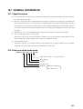
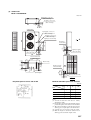
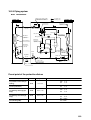
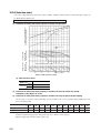
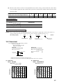
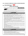
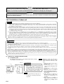
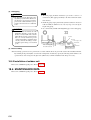
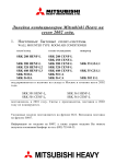
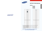
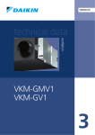
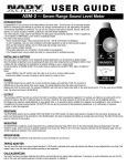
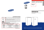
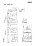
18. FLOOR STANDING TYPE
PACKAGED AIR-CONDITIONER
Split system, Air to air
heat pump type
(
)
FDF508HES-SB
601
CONTENTS
18.1 GENERAL INFORMATION ........................................................................ 603
18.1.1 Specific features ................................................................................. 603
18.1.2 How to read the model name ............................................................. 603
18.2 SELECTION DATA ..................................................................................... 604
18.2.1 Specifications ...................................................................................... 604
18.2.2 Range of usage & limitations ............................................................. 605
18.2.3 Exterior dimensions............................................................................ 606
18.2.4 Exterior appearance............................................................................ 608
18.2.5 Piping system ...................................................................................... 609
18.2.6 Selection chart .................................................................................... 610
18.2.7 Noise level ........................................................................................... 611
18.3 ELECTRICAL DATA ................................................................................... 612
18.3.1 Electrical wiring .................................................................................. 612
18.4 OUTLINE OF OPERATION CONTROL BY MICROCOMPUTER ............. 613
18.5 APPLICATION DATA ................................................................................. 613
18.5.1 Installation of indoor unit ................................................................... 614
18.5.2 Installation of outdoor unit................................................................. 616
18.6 MAINTENANCE DATA ............................................................................... 616
602
18.1 GENERAL INFORMATION
18.1.1 Specific features
(1)
Less refrigerant charge amount due to use of double phase refrigerant flow system. The total refrigerant charge amount has
been reduced by more than 50%.
(2)
The indoor outdoor interconnection signal wiring has been done away with. The microcomputer chip is installed in the
indoor and outdoor unit. There is no need for the unit to communicate between the outdoor and indoor units so the unit is
more resistant to electromagnetic noise thus the incidence of microcomputer malfunction has been reduced. The compressor
in the outdoor unit has its own self protection function, that reacts according to abnormal high pressure and excessive high
temperature.
(3)
All models have service valves protruding from the outdoor unit for faster flare connection work in the field.
(4)
The connecting piping can have a 4-way off-take.
The direction of the off-take can meet the installation conditions. Selection can be made from among all directions: left,
right, rear-right and floor pull-out. This provides a wide range of installation freedom.
(5)
Auto-Swing Design Used.
Adjustment is automatic to a maximum of 90° in the left and right direction. Up/down adjustment is done manually.
Adjustment can be made to 20° in the up direction and 30° in the down direction.
18.1.2 How to read the model name
Example: FDF
50 8
H
ES -SB
Applicable power source... See the specifications
Heat pump type
Series No.
Product capacity
Model name
FDF : Floor standing type
FDC : Outdoor unit
603
18.2 SELECTION DATA
18.2.1 Specifications
Model FDF508HES-SB
FDF508HES-SB
Model
Item
FDF508H
Nominal cooling capacity(1)
W
Nominal heating capacity(1)
W
FDC508HES3B
12500
14000
Power source
3 Phase, 380V, 50Hz
Operation data(3)
Cooling input
kW
5.42
Running current (Cooling)
A
9.8
Power factor (Cooling)
%
84
kW
4.97
Running current (Heating)
A
9.3
Power factor (Heating)
%
81
Inrush current (L.R.A)
A
Heating input
Noise level(4)
Exterior dimensions
Height × Width × Depth
Net weight
Refrigerant equipment
Compressor type & Q’ty
Motor
74
dB(A)
Hi: 49 Lo: 45
55
mm
1850 × 600 × 350
1250 × 920 × 340
kg
46
101
—
GU-A5570ES41 × 1
kW
Starting method
Heat exchanger
—
3.75
—
Line starting
Louver fines & inner grooved tubing
Refrigerant control
Slitted fines & bare tubing
Capillary tube
Refrigerant
R22
Quantity
Refrigarant oil
kg
—
r
—
1.9 [Pre-charged up to the piping length of 5m]
1.6 (BARREL FREEZE 32SAM)
Defrost control
IC controlled de-icer
High pressure control
High pressure switch
Air handling equipment
Sirocco fan × 1
Fan type & Q’ty
Moter
W
Starting method
Air flow (Standard)
CMM
Fresh air intake
Air filter, Q’ty
Shock & vibration absorber
Electric heater
Operation control
Operation switch
Room temperature control
130 × 1
65 × 2
Line starting
Line starting
Hi: 28 Lo: 23
110
Unavailable
—
Polypropylene net (washable)
—
Rubber sleeve (for fan motor)
Rubber mount (for compressor)
—
40 (Crank case heater)
Control switch
– (Indoor unit side)
— (Can be incorporated: PTC Heater 2.2 kW)
—
W
Electric heater
Propeller fan × 2
Thermostat by electronics
Safety equipment
Internal thermostat for fan motor
Frost protection thermostat.
Installation data
Refrigerant piping size
mm
(in)
—
Internal thermostat for fan motor.
Abnormal discharge temperature protection.
Liquid line: φ9.52 (3/8″) Gas line: φ19.05 (3/4″)
Connecting method
Flare piping
Drain hose
(Connectable with VP20)
Insulation for piping
—
Neccessary (both Liquid & Gas lines)
Accessories
Mounting kit.
Optional parts
Electric heater
Notes (1) The data are measured at the following conditions.
Item
Operation
Cooling
Heating
Indoor air temperature
DB
WB
27˚C
19˚C
20˚C
—
Outdoor air temperature
DB
WB
35˚C
24˚C
7˚C
6˚C
Standards
ISO-T1 JIS B8616
(2) This packaged air conditioner is manufactured and tested in conformity with the following standard. ISO-T1 "UNITARY AIR CONDITIONERS"
(3) The operation data indicate when the air-conditioner is operated at 380V 50Hz.
(4) Indicators the value at mild mode.
604
18.2.2 Range of usage & limitations
Model
FDF508HES-SB
Item
Indoor return air temperature
(Upper, lower limits)
Refer to the selection chart
Outdoor air temperature
(Upper, lower limits)
Refrigerant line (one way) length
Vertical height difference between
outdoor unit and indoor unit
Power source voltage
Voltage at starting
Max. 50 m
Max. 30 m (Outdoor unit is higher)
Max. 15 m (Outdoor unit is lower)
Rating ± 10%
Min. 85% of rating
Frequency of ON-OFF cycle
Max. 10 times/h
ON and OFF interval
Min. 3 minutes
605
18.2.3 Exterior dimensions
(1) Indoor unit
Model FDF508H
Unit: mm
Opening for exit piping & wiring (Bottom)
(ø88)
1000
100
280
274
290
298
50
Space for installation and service
50
Service
space
600
Drain (VP20)
30
30
600
62
50
Gas piping
ø19.05 (3/4")
Liquid piping
ø9.52 (3/8")
76
600
480
340
269
350
60
60
Control switch
175
635
250
Gas piping
835
Liquid piping
ø9.52 (3/8")
100
40
145
100
615
ø19.05 (3/4")
540
770
1850
526.5
Drain (VP20)
75
560
Opening for exit piping & wiring (Rear)
(ø88 knockout)
606
220
330
Opening for exit piping & wiring
(ø88 knockout on both side)
(2) Outdoor unit
Model FDC508HES3B
Unit: mm
Liquid piping: ø 9.52 (3/8")
(Flare connecting)
46
100
48
50
Gas piping: ø 19.05 (3/4")
(Flare connecting)
Terminal block
Liquid piping: ø 9.52 (3/8")
(Flare connecting)
Gas piping: ø 19.05 (3/4")
(Flare connecting)
Opening for electric wiring
1250
A
55
50
110
578
195
50
Opening for piping
and electric wiring
50
10
195
110
555
Opening for
electric wiring
50
50
27
15
Opening for piping
and electric wiring
920
Holes for anchor bolt
(M10 × 4pcs.)
580
175
15
103
295
50
15
Holes for drain
(ø 20 × 3pcs.)
50
237
Opening for piping
and electric wiring
70
50
Electric wiring
150
47
35
35
55
15
380
340
15
165
15
Opening for electric wiring
40
50
VIEW A
Required space for service and air flow
Minimum allowable space to the obstacles
Unit:mm
L3
L2
Installation
type
Air inlet
L4
Air
inlet
L1
Service
space
I
II
III
L1
Open
Open
500
L2
300
5
Open
L3
150
300
150
L4
5
5
5
Mark
Air outlet
Notes
(1) Avoid the location where four sides are entirely
surrounded by walls.
(2) Fix the unit by anchor bolts without fail. Restrict the
protrusion length of anchor bolt to 15 mm and under.
(3) When strong wind blows against the unit, direct the
discharge port at a right angle to the wind direction.
(4) Secure the space of 1 m and over at the top of unit.
(5) Make the height of obstruction wall in front of
discharge port lower than the height of unit.
607
18.2.4 Exterior appearence
(1) Indoor unit
Model
FDF508H
Air outlet grille
Ceramic white
Front panel
Ceramic white
Side panel
Ceramic white
Air inlet grille
Ceramic white
Bottom panel
Warm gray
(2) Outdoor unit
Model
FDC508HES3B
Polar white
608
18.2.5 Piping system
Model FDF508HES-SB
High pressure switch (63H2)
(For fan motor control)
Indoor unit
Cooling cycle
4-way valve
Strainer
Gas line
(ø19.05)
Outdoor unit
Heating cycle
Thermistor
(ThO-A)
Service valve
(Flare connecting)
Check joint
Check joint
Thermistor
(ThI-A)
Capillary tube
Oil separator
Thermistor
(ThO-D)
Heat exchanger
Capillary
tube
Thermistor
(ThI-R)
Compressor
Capillary
tube
Heat exchanger
Check
joint
Capillary
tube
Subcooling
coil
Solenoid
valve (SV1)
Strainer
Liquid line
(ø9.52)
Accumulators
Solenoid Thermistor
valve (SV2)
(ThO-R)
Check valve
Strainer
Strainer
Service valve
(Flare connecting)
Capillary tube
Flare connecting
Preset point of the protective divices
Parts name
Thermistor
(for protection over loading in
heating)
Mark
ThI-R
Equipped unit
FDF508HES-SB
OFF
ON
68 °C
61 °C
OFF
ON
2.5 °C
10 °C
Indoor unit
Thermistor
(for frost prevention)
Thermistor
(for detecting discharge pipe
temp.)
ThO-D
Outdoor unit
OFF
ON
135 °C
90 °C
Thermistor
(for detecting heat exchanger
temp.)
ThO-R
Outdoor unit
OFF
ON
70 °C
60 °C
High pressure switch
(for controlling FMo)
63H2
Outdoor unit
OFF 2.50MPa
ON 2.06MPa
609
18.2.6 Selection chart
Correct the cooling and heating capacity in accordance with the conditions as follows. The net cooling and heating capacity can
be obtained in the following way.
Net capacity = Capacity shown on specification × Correction factors as follows.
Coefficient of cooling and heating capacity in relation to temperature
(1) Coefficient of cooling and heating capacity in relation to temperatures
Cooling
Heating
Cooling operation
Outdoor air D.B.
temperature (˚CD.B.)
Heating operation
Indoor air D.B.
temperature (˚CD.B.)
Applicable range
Indoor air W.B. temperature (˚CW.B.) ISO-T1 Standard condition
ISO-T1 Standard condition
Outdoor air W.B. temperature (˚CW.B.)
(a) Table of bypass factor
Item
Model
FDF508HES-SB
High
0.032
Low
0.022
Air flow
(2) Correction of cooling and heating capacity in relation to air flow rate control (fan speed)
Coefficient: 1.00 at High, 0.95 at Low
(3) Correction of cooling and heating capacity in relation to one way length of refrigerant piping
It is necessary to correct the cooling and heating capacity in relation to the one way equivalent piping length between the
indoor and outdoor units.
Equivalent piping length (1)
m
7.5
10
15
20
25
30
35
40
45
50
55
Heating
1.0
1.0
1.0
1.0
1.0
0.998
0.998
0.993
0.993
0.988
0.988
Cooling
1.0
0.995
0.980
0.970
0.955
0.945
0.930
0.920
0.905
0.895
0.880
Note (1) Equivalent piping length can be obtained by calculating as follows.
[φ19.05(3/4″)]: Equivalent piping length = Real piping length + (0.15 × Number or bends in piping)
[Equivalent piping length < Limitation length of piping + 5m]
610
(4) When the outdoor unit is located at a lower height than the indoor unit in cooling operation and when the outdoor unit is
located at a higher height than the indoor unit in heating operation, the following values should be subtracted from the values
in the above table.
Height difference between the indoor unit and
outdoor unit in the vertical height difference
5m
10m
15m
20m
25m
30m
Adjustment coefficient
0.01
0.02
0.03
0.04
0.05
0.06
Piping length limitations
Model
FDF508HES-SB
Item
Max. one way piping length
50m
Max. vertical height difference
Outdoor unit is higher : 30m, Outdoor unit is lower : 15m
Note (1) Values in the table indicate the one way piping length between the indoor and outdoor units.
How to obtain the cooling and heating capacity
Example : The net cooling capacity of the model FDF508HES-SB with the air flow “High”, the piping length of 15m, the outdoor unit located
5m lower than the indoor unit, indoor wet-bulb temperature at 19.0 ˚C and outdoor dry-bulb temperature 35 ˚C is
Net cooling capacity
=
×
12500
FDF508HES-SB
×
1.00
Air flow
“High”
×
(0.98 - 0.01)
1.0
12125 w
=
Length 15m.
Height difference 5 m
Factor by air
temperatures
18.2.7 Noise level
Notes (1)The data are based on the following conditions.
Ambient air temperature:
Indoor unit 27°C DB, 19°C WB
Outdoor unit 35°C DB,
Indoor unit
Measured based on JIS B 8616
Mike position as below
Microphone
1m
1m
Indoor unit
Outdoor unit
Measured based on JIS B 8616
Mike position: at highest noise level
in position as below
Distance from front side
1m
Height
1m
(2) The data in the chart are measured in an unechonic room.
(3) The noise levels measured in the field are usually higher than the data because of reflection.
(1) Indoor unit
Model
(2) Outdoor unit
Model
FDF508H
Noise level 49 dB (A) at HIGH
45 dB (A) at LOW
FDC508HES3B
Noise level 55 dB (A)
70
70
70
70
N70
N70
60
60
N60
50
50
N50
40
40
N40
30
30
N2
125
250
500
60
N60
50
50
N50
40
40
N40
30
30
N30
0
20
63
Souud pressure level
(standard 0.0002µbar)
Souud pressure level
(standard 0.0002µbar)
60
1000
2000
4000
Mid octave band frequency (Hz)
N2
20
8000
N30
0
20
63
125
250
500
1000
2000
4000
20
8000
Mid octave band frequency (Hz)
611
RD
X05
X08
X04
X07
BL
X06
X03
WH
1 2
BK/WH
3 28
RD/WH
H L UH
X02 X03 X04
Mark
CFI
CFO1,2
CH
CM
CnA ~ Z
CT1,2
F
FMI
FMO1,2
LED
LM
LS
NR
SSR
PC
SV1,2
SW
SW3
TB
ThI-A
CF01
12 13
H L UH
(49FO2)
FMO2
Parts name
Capacitor for FMI
Capacitor for FMO
Crankcase heater
Compressor motor
Connector ( mark)
Current sensor
Fuse
Fan motor (indoor unit)
Fan motor (outdoor unit)
Indication lamp
Louver motor
Limit switch
Surge suppressor
Auxiliary relay (for LM)
Photo coupler
Solenoid coil (for control)
Switch (ON/OFF)
Changeover switch
Terminal block ( mark)
Thermistor
Meaning of marks
Printed circuit board
X02
W
CT2
CM
V
WH
X01
CT1
RD
WH
U
(49FO1)
FMO1
OR/WH
Y/GN
BL
6
OR/WH
4
CF02
52C
BR
BK
SV1
X08
22
26
27
7
6
Vao
Tro
BK/WH
BR/WH
BL/WH
Tho-R Tho-D Tho-A
14V
CnA1 CnA2
(Checker)
CnE
Parts name
X07
23 25
63H2
Auxiliary relay
Auxiliary relay
High pressure switch (for control)
Terminal (F)
Connector
Indication lamp (Green)
Indication lamp (Red)
21
SV2
X3~7
X01~08
63H2
v
■
LED-G
LED-R
X06
20
A2
Thermistor
Thermistor
Thermistor
Thermistor
Transformer (indoor unit)
Transformer (outdoor unit)
Varistor
Varistor
4-way valve solenoid
Internal thermostat for FMI
Internal thermostat for FMo
Magnetic contactor for CM
X01
19
18
A1
BR/WH
Mark
ThI-R
Tho-A
Tho-D
Tho-R
TrI
TrO
Val
Vao
20S
49FI
49FO1,2
52C
X05
17
16
14 15
20S
GR
2
BK
5
GR
BK
BK
3
BL
1
BL
52C
BL
N
P
NR
BK
BK/WH
BL
BK/RD
3
4
5
3
4
5
Mark
BK
BL
BR
GR
OR
P
RD
WH
WH
BR
BL
BK
9
2
1
14
10
Color
Black
Blue
Brown
Gray
Orange
Pink
Red
White
2
TB
RD
1
2/N
TB
1
Color mark
(Run)
LED-G
(Check)
LED-R
CnL
BK
X6
CnZ
LM
3
CnZ
Mark
BK/RD
BK/WH
BL/WH
BR/WH
OR/WH
RD/WH
Y/GN
PC
X5
L
8
X3
OR
CnF1
OR
OR
X7
CFI
X3 X6
X4 X7
X5
Color
Black/Red
Black/White
Blue/White
Brown/White
Orange/White
Red/White
Yellow/Green
5
6
OR
CnF1
FMI
(49FI)
H
7
X4
Indoor Unit
BK / WH
RD/WH
Y/GN
L2 WH
L3 BL
BK
BL
BR
WH
OR
OR
CnM1
BK
BL
BR
WH
OR
OR
CnM2
RD
F(3.15A)
DR
CH
BR
CnR
BK/RD
PC
BL/WH
PC
DR
220V
P
Outdoor Unit
BK
Val
BK
CnW1
SW3
OFF
1 2 3 4
ON
12V
BR CnW2
Tr I
BK RD
CnQ
Test
220V
Printed circuit board
13
PC
GR
TB
L1 RD
Y / GN
SSR
OR
OR
WH
WH
RD / WH
RD
Y / GN
BL / WH
BL
WH
WH
CnT
CnH
CnN
CnB
612
CnS
BL CnZ BL
BL
BL
CnK2
(3)
CnB2
CnN
RD
RD
(3)
BK
BK
BK
BK
ThI–A
Option
LS
SW
Option
Control switch
LED
ThI–R
52H
XR5
XR3
XR1
BK
BK
CnH2
XR4
XR2
Model
CnO
Power source
3 Phase 380V 50Hz
18.3 ELECTRICAL DATA
18.3.1 Electrical wiring
FDF508HES-SB
18.4 OUTLINE OF OPERATION CONTROL BY MICROCOMPUTER
This is same as FDUR heat pump series. Refer to page 306.
18.5 APPLICATION DATA
SAFETY PRECAUTIONS
• Please read these “Safety Precautions” first then accurately execute the installation work.
• Though the precautionary points indicated herein are divided under two headings. WARNING and CAUTION , those
points which are related to the strong possibility of an installation done in error resulting in death or serious injury are listed in
the WARNING section. However, there is also a possibility of serious consequences in relationship to the points listed in the
CAUTION section as well.
In either case, important safety related information is indicated, so by all means, properly observe all that is mentioned.
• After completing the installation, along with confirming that no abnormalities were seen from the operation tests, please explain
operating methods as well as maintenance methods to the user (customer) of this equipment, based on the owner’s manual.
Moreover, ask the customer to keep this sheet together with the owner’s manual.
WARNING
• This system should be applied to places of office, restaurant, residence and the like. Application to inferior
environment such as engineering shop could cause equipment malfunction.
• Please entrust installation to either the company which sold you the equipment or to a professional contractor.
Defects from improper installations can be the cause of water leakage, electric shocks and fires.
• Execute the installation accurately, based on following the installation manual. Again, improper installations can
result in water leakage, electric shocks and fires.
• When a large air-conditioning system is installed to a small room, it is necessary to have a prior planned countermeasure for the rare case of a refrigerant leakage, to prevent the exceeding of threshold concentration.
In regards to preparing this countermeasure, consult with the company from which you perchased the equipment,
and make the installation accordingly. In the rare event that a refrigerant leakage and exceeding of threshold
concentration does occur, there is the danger of a resultant oxygen deficiency accident.
• For installation, confirm that the installation site can sufficiently support heavy weight. When strength is insufficient,
injury can result from a falling of the unit.
• Execute the prescribed installation construction to prepare for earthquakes and the strong winds of typhoons and
hurricanes, etc. Improper installations can result in accidents due to a violent falling over of the unit.
• For electrical work, please see that a licensed electrician executes the work while following the safety standards
related to electrical equipment, and local regulations as well as the installation instructions, and that only exclusive
use circuits are used.
Insufficient power source circuit capacity and defective installment execution can be the cause of electric shocks
and fires.
• Accurately connect wiring using the proper cable, and insure that the external force of the cable is not conducted
to the terminal connection part, through properly securing it. Improper connection or securing can result in heat
generation or fire.
• Take care that wiring does not rise upward, and accurately install the lid/service panel. Its improper installation
can also result in heat generation or fire.
• When setting up or moving the location of the air conditioner, do not mix air etc. or anything other than the
designated refrigerant within the refrigeration cycle.
Rupture and injury caused by abnormal high pressure can result from such mixing.
• Always use accessory parts and authorized parts for installation construction. Using parts not authorized by this
company can result in water leakage, electric shock, fire and refrigerant leakage.
CAUTION
• Execute proper grounding. Do not connect the ground wire to a gas pipe, water pipe, lightning rod or a telephone
ground wire. Improper placement of ground wires can result in electric shock.
• The installation of an earth leakage breaker is necessary depending on the established location of the unit. Not
installing an earth leakage breaker may result in electric shock.
• Do not install the unit where there is a concern about leakage of combustible gas.
The rare event of leaked gas collecting around the unit could result in an outbreak of fire.
• For the drain pipe, follow the installation manual to insure that it allows proper drainage and thermally insulate it
to prevent condensation. Inadequate plumbing can result in water leakage and water damage to interior items.
613
NOTICE
All Wiring of this installation must comply with NATIONAL, STATE AND LOCAL REGULATIONS. These instructions
do not cover all variations for every kind of installation circumstance. Should further information be desired or should particular
problems occur, the matter should be referred to Mitsubishi Heavy Industries, Ltd. through your local distributor.
WARNING
BE SURE TO READ THESE INSTRUCTIONS CAREFULLY BEFORE BEGINNING INSTALLATION. FAILURE TO
FOLLOW THESE INSTRUCTIONS COULD CAUSE SERIOUS INJURY OR DEATH, EQUIPMENT MALFUNCTION
AND/OR PROPERTY DAMAGE.
18.5.1 Installation of indoor unit
Request
™Please do not install and use the air-conditioning equipment in locations such as the following:
(1) In the vicinity of equipment which generates electromagnetic waves, such as that often found in hospitals, or in the vicinity of equipment
which generates high frequency waves: Installation in such locations is to be avoided as the generation of electromagnetic noise can cause
the controller to operate incorrectly.
(2) Areas which are exposed to salt air wind, such as coastal regions: Salt air can accelerate the corrosion of outer plating and the heat exchanger.
(3) Kitchens, machinery plants, and other similar locations where splashing and/or spraying of oil and grease occurs frequently or where a large
amount of heated air is present: Grease and hot air can easily enter and disrupt the operation of the indoor unit, and thus, the unit should not
be installed in such locations. In addition, these factors can also lead to reduced performance and/or corrosion of the heat exchanger as well
as resulting in damage to plastic parts.
(4) Any location where there is a possibility that corrosive gasses (sulfurous acid, etc.) or inflammable gasses (paint thinner vapor or gasoline
vapor, etc.) could be produced or could accumulate; also, installation and use of this air conditioner equipment in locations where volatile
inflammable substances are handled is to be avoided: These factors can lead to corrosion of the heat exchanger and to damage to plastic parts.
In addition, there is also a possibility that inflammable gasses could be ignited in the presence of the air-conditioner.
™If spatter generated during welding and other similar operations comes into contact with the indoor unit, it may result in the unit being damaged.
Therefore, in addition to requesting that the utmost care be taken when performing this type of work in the vicinity of the air-conditioner
equipment, it is also requested that the unit be covered to prevent spatter from passing to its interior.
CAUTION
™It is important that the following safety precautions be followed during installation of the air-conditioning equipment:
¡Do not place the air conditioner’s remote control unit in any location where it will be exposed to direct sunlight as this can cause the remote
control unit to be damaged or warped.
¡The equipment must be grounded; the ground wire should not be connected to either gas pipe, water pipe, lightning rod, or telephone ground
wires. Incorrect operation of the air conditioner or electric shocks can result if the grounding is not performed correctly.
¡An earth leakage breaker is required to be fitted in order to provide protection against the possibility of electric shocks, fires, and other similar
accidents.
¡Ensure that the air conditioner is securely installed in a location which is fully capable of supporting its weight. Failure to do so could result in a
number of different problems such as the unit toppling over and causing injury or generating increased operation noise due to vibration.
¡If there is a possibility that the in-door unit’s refrigerant concentration could exceed the threshold concentration (0.3 kg/m3) and result in
suffocation should a leakage of this gas occur, it will be necessary to provide an opening between the room containing the indoor unit and
neighboring rooms or to provide mechanical ventilating equipment which operates in response to gas leak warnings. Consult with staff at your
local sales outlet when purchasing such products.
(1) Selection of a suitable installation location
(a) Installation space
The dimensions shown below are the minimum which must be available
for installation of the indoor unit.
50
Unit: mm
100
1000
50
Service
space
614
50
600
600
Request Obtain the consent of the customer to
install the indoor unit in a location
which satisfies the following conditions:
¡ Warm and cold air must be able to
WARNING
dissipate freely.
¡ It must be possible to easily
¡ Install the indoor securely in a location
connect wiring and piping to the
which is fully capable of supporting its
outdoor.
weight. Installing in a location which is
¡
The installation of a drain must be
not sufficiently reinforced or supported
possible.
may result in the indoor unit toppling and
¡ The section of floor for installation
falling, resulting in damage or injury.
must be sufficiently reinforced.
¡ Direct sunlight must not fall on the
in-door unit.
Request
¡ There must be no obstacles or
¡ It is important that enough space is
blockages in the vicinity of the
provided for performing maintenance
suction air and discharge air
operations.
openings.
¡ There must be no possibility of
faulty operation of a fire alarm, as
must there be no possibility of short
circuits.
(2) Transporting and installing the unit
(a) Transporting
Front surface facing
upward
Request
¡ When transporting the unit to the final mounting location, keep it in its original packing as long
as feasible.
¡ When the situation demands that the unit be unpacked for transportation, wrap using nylon
sling and take care to ensure that the unit is not damaged.
Note (1) Do not hold the unit by the air inlet grill, by the air outlet grill, or by any other plastic
parts.
¡ When placing the unit down after packaging has been removed, please ensure that it is always
positioned with the front surface facing upward.
(b) Topple prevention overview
Request
Tapping screws
¡ Mount the unit on a level surface; forward,
Topple preventer
backward, left, or right inclinations must not
(Secured with
round wood screws)
The unit will topple over quite
easily; it must be secured in place
as illustrated.
L-angle
(3) Refrigerant piping
exceed 1˚.
Please refer to the outdoor unit’s instruction manual with regard to the installation of refrigerant piping.
(b) Control box position and power cord path
Control
box
(a) Piping and wiring outlets
Control box
For rear pull-out
(1 location)
(φ 88 knockout hole)
For bottom
pull-out (φ 88)
(φ 88 knock-out hole)
For side pull-out
(left and right)
Clamp
¡ Remove the suction grill to
find the control box in the
position indicated in the
diagram above. Remove the
cover to perform the necessary work.
¡ The power line must
pass through the clamp
and be secured by the
clamp.
615
(4) Drain piping
WARNING
¡ The drain must not be allowed flow into
any drainage systems where sulfurous or
any other types of poisonous gas may be
present as it could result in these gasses
passing to the interior of the air conditioned
room.
Request
¡ The drain piping should be insulated to prevent the occurrence of
condensation. (This applies particularly to the indoor unit itself and the
unit’s interior.)
¡ Install the piping sloping downwards (with an declination of between
1/50 and 1/100); in addition do not create any traps or rises along the
length of the piping.
CAUTION
¡ Follow carefully the instructions in the
installation manual to ensure that the
drain is securely installed in a manner
which allows free flow of water and also
that it is correctly insulated to prevent
condensation. Failure to install the drain
correctly can lead to the leakage of water
and subsequent damage to household
goods.
¡ Use commercially available VP-20 rigid PVC pipe for the drain piping.
No rises
No traps
Do not place the
end in water.
Make the drain piping
short and downward.
(5) Electrical wiring
• Electrical wiring operations are to be performed in accordance with the directions given in the outdoor unit’s installation manual.
By switching the dip switch (SW3-3) on the indoor unit printed circuit board (“Specify the following switch number.”), the
operation mode can be changed to the quiet mode (mild mode). Confirm at installation and change if necessary.
18.5.2 Installation of outdoor unit
This is same as FDUR heat pump series. Refer to page 330.
18.6 MAINTENANCE DATA
This is same as FDUR heat pump series. Refer to page 340.
616