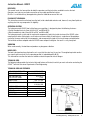
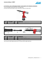
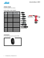
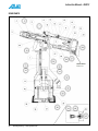
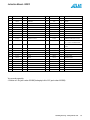
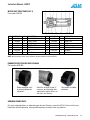
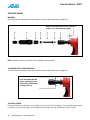
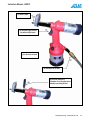
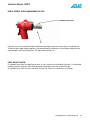
1
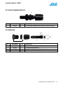
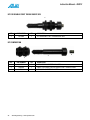
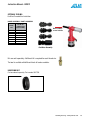
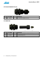
RIV912
PULL-TO-STROKE SPIN-PULL TOOL
FOR RIVET NUTS FROM #4-40 to 1/2” and M3 TO M12
AND RIVET STUDS #8-32 TO 5/16” AND M4 TO M8
Operating Instructions
Instruction Manual - RIV912
2
PennEngineering • www.pemnet.com
Instruction Manual - RIV912
NOTE: THE RIV912 TOOL COMES WITHOUT NOSE ASSEMBLY KITS.
NOSE ASSEMBLY KITS HAVE TO BE ORDERED SEPARATELY ACCORDING TO THE USER NEEDS.
1. Kit assembly with toothed ring nut (wrench is no longer necessary).
2. Tie rods are now replaced by commercial screws.
3. One position trigger mechanism.
4. Light weight.
5. Convenient.
6. The adjustment ring can be blocked using the nut.
7. Easily adjusted after tooling changeover.
PennEngineering • www.pemnet.com
3
Instruction Manual - RIV912
GENERAL INFORMATION
MANUFACTURER
Rivit S.r.l. was born in 1973, it produces and distributes in Fasteners and Tools for Fixings (tools for rivets and rivet
nuts). The Company boasts much technical experience and offers a wide range of products related to fastening
systems.
ASSISTANCE
In case you need any assistance concerning the use and the maintenance of the tool, or in case you need to order
any spare parts, you shall contact your local authorised dealer (or Rivit S.r.l. directly) specifying the identification/
serial numbers of the tool, written on its outer casing.
CERTIFICATION AND EC MARKING
The tool is manufactured in compliance with the European Directives, which are in force when the tool itself is put
on the market. As the tool is not included in ENCLOSURE IV of DIRECTIVE 2006/42/EC, Rivit S.r.l. issues a selfcertification to apply the EC marking.
WARRANTY
The warranty has a validity of 12 months, as of the date indicated on the invoice.
The warranty only covers replaced parts; labor is not included.
The following are not covered by warranty: standard accessories and tool damages caused by:
• transport and/or handling, user’s mistakes,
• failed servicing/maintenance, as indicated in section 7 of this manual,
• faults and/or breakages that are not attributable to tool anomalies,
• normal consumption of consumables.
The warranty is invalidated both in case of unauthorized tampering/replacements of tool components and in case of
use of accessories, tools or consumables different to those recommended by the manufacturer, which could even
cause injuries to the tool’s user.
Rivit S.r.l. assumes responsibilities only if the tool is originally defective, but declines all forms of responsibility if
the user fails to follow the instructions given.
OPERATING SYSTEM
The hydro-pneumatic RIV912 tool, with oil pressure regulation, is designed to place female threaded inserts (from
#4-40 to 1/2” and M3 to M12) and male threaded inserts (from #8-32 to 5/16” and M3 to M8). The hydro-pneumatic
system and the mechanical components used inside the RIV912, when compared with other riveting tools, are more
reliable. There is less wear and tear of the components, consequently the tool will last much longer and work better.
The technical solutions adopted make the RIV912 more compact and lighter.
MANUAL STRUCTURE
This instruction manual must be read with particular attention by the Customer, as the correct pre-arrangement,
installation and use of the tool, are the correct basis for a good relationship between Manufacturer and Customer.
PURPOSE AND CONTENTS
The manual herein has the purpose of providing the Customer with all the information needed not only to use the
tool correctly, but also to manage it self-sufficiently and safely. It includes information concerning technical aspects,
operation, maintenance, spare parts and safety.
Users and Qualified Technicians must read the instructions given herein thoroughly before starting to use the
tool. If you have any doubts on the meaning of the instructions given, please do not hesitate to contact Rivit S.r.l.
for further explanations.
4
PennEngineering • www.pemnet.com
Instruction Manual - RIV912
RECEIVERS
The manual herein has been written for both the operators and the technicians enabled to service the tool.
Operators must not carry out jobs reserved to service and/or qualified technicians.
Rivit S.r.l. is not liable for any damage deriving from the failed observance of this rule.
PLACING OF THE MANUAL
This instruction manual must be kept near the tool, inside a dedicated container and, above all, away from liquids or
anything else that may compromise its legibility.
OPERATING SYSTEM
The hydro-pneumatic RIV912 tool, with oil pressure regulation, is designed to place the following fasteners:
• Female threaded rivet nuts (from #4-40 to 1/2” and M3 to M12)
• Male threaded rivet studs (from #8-32 to 5/16” and M4 to M8)
The hydro-pneumatic system and the mechanical components used in the inside structure of the RIV912, when
compared with other riveting tools, result to be much more reliable. A tool feature is a reduction of the problems
caused by the wear and tear of the components, and consequently the tool will last much longer and work better.
The technical solutions adopted make the RIV912 more compact and lighter: the result is a very handy tool.
VIBRATION
When used correctly, the tool does not produce any dangerous vibration.
NOISE LEVEL
The tool is designed and manufactured in such a way that the noise level is very low. The weighed equivalent continuous acoustic pressure level A in the operator position is indeed below 80 dB (A).
This information can allow the tool user to better evaluate the possible risks of danger.
TECHNICAL DATA
The following table provides the technical data and features of the tool, to which you must refer when contacting the
ATLAS® Technical Assistance Department at PennEngineering.
TECHNICAL DATA AND FEATURES
AIR WORKING PRESSURE
MAX AIR PRESSURE
AIR CONSUMPTION PER CYCLE AT 6 BAR
MAX STROKE
MAX. AXIAL PULLING LOAD
MOTOR SPEED (SPIN ON)
MOTOR SPEED (SPIN OFF)
WEIGHT
VIBRATIONS
NOISE LEVEL
90 PSI / 6 BAR
70 to 100 PSI / 5 to 7 BAR
457.5 cu. in.
7.5 liter
.256” / 6.5 mm
4721 lbs @ 90 PSI
21 kN @ 6 BAR
1600 rpm
2000 rpm
5 lbs. / 2.3 kg
< 2.5 m/s2
78.5 dB (A)
PennEngineering • www.pemnet.com
5
Instruction Manual - RIV912
NOSE ASSEMBLIES AND STANDARD ACCESSORIES
The nose assemblies stated hereafter refers to standard tools.
Any special tool could consequently require special parts, different than those listed.
REF.
1
2
3
4
5
—
PART NUMBER
3440900
2533800
0207300
3064400
4091400
—
QTY
1
1
1
1
1
1
DESCRIPTION
RIV912-HYDRO-PNEUMATIC TOOL FOR INSERTS (IN PVC CASE)
EMERGENCY AND STROKE REGULATION PIN
UNIVERSAL KEY
HYDRAULIC OIL TYPE ISO VG 32 100CC
RUBBER PROTECTION
INSTRUCTION MANUAL
OPTIONAL ACCESSORIES
Depending on the fastener style, different accessories are available.
6
PennEngineering • www.pemnet.com
Instruction Manual - RIV912
KIT FOR SPECIAL HEAD. EXTENSION ON REQUEST: NOT INCLUDED IN THE STANDARD ACCESSORIES
The nose assemblies stated hereafter refers to standard tools.
Any special tool could consequently require special parts, different than those listed.
1
REF.
1
REF.
2
3
PART NUMBER
3531800
QTY
1
DESCRIPTION
KIT 912 - SPECIAL EXTENDED HEAD
PART NUMBER
3446600
3446900
QTY
1
1
DESCRIPTION
90 MM EXTENDED SLEEVE
90 MM INTERNAL EXTENDED SLEEVE
You can reach a total head extension of 6.5”/165 mm with the above two items.
PennEngineering • www.pemnet.com
7
Instruction Manual - RIV912
OPTIONAL TOOLING
For Blind Threaded Insert Installation.
NOSE ASSEMBLY PART NUMBERS
Thread
Size
#4-40
#6-32 #8-32 #10-24
#10-32 1/4-20
1/4-28
5/16-18
5/16-24
3/8-16
3/8-24
1/2-13
M3
M4 M5 M6
M8 M10
M12
Part No. For
Complete Insert
Nose Assembly
Part No. For
Replacement
SHCS / Mandrel(1)
4326700
3755100
3755500
—
3755900
3756100
—
3756300
—
3756700
—
4361600
3441100
3441200
3441300
3441400
3441500
3441600
3441700
MC-91251A078 (50/box)
IN-14328 (100/box)
IN-03190 (100/box)
IN-08823 (100/box)
IN-07085 (100/box)
IN-05336 (100/box)
IN-08057 (100/box)
IN-04153 (100/box)
IN-10834 (100/box)
IN-15776 (100/box)
IN-16488 (50/box)
—
IN-06219 (200/box)
IN-03023 (200/box)
IN-03038 (200/box)
IN-13128 (200/box)
IN-21070 (100/box)
IN-03088 (100/box)
—
(1) Replacement mandrels sold in box quantities shown above.
HEAD RING NUT
Can be ordered separately. Part number 0327700.
8
PennEngineering • www.pemnet.com
Nose assembly
screws into here
Insert Nose Assembly
Instruction Manual - RIV912
KIT FOR BLIND THREADED INSERT #4-40
1
REF.
1
PART NUMBER
4326700
QTY
1
DESCRIPTION
KIT FOR BLIND THREADED INSERT #4-40 SOCKET HEAD CAP SCREW
KIT COMPOSITION
4
5
3
2
REF.
2
3
4
5
PART NUMBER
4326300
4326400
MC-91251A078 (50/box)
4326500
QTY
1
1
1
1
DESCRIPTION
HEAD WITH RING NUT FOR #4-40 SCREW
ADAPTER FOR #4-40 SCREW (HOLE Ø 3.0)
SOCKET CAP SCREW #4-40 X 1.5”
HEXAGONAL JOINT WITH SPRING FOR #4-40 SCREW
PennEngineering • www.pemnet.com
9
Instruction Manual - RIV912
KIT FOR BLIND THREADED INSERT #6-32
1
REF.
1
PART NUMBER
3755100
QTY
1
DESCRIPTION
KIT FOR BLIND THREADED INSERT #6-32 SOCKET HEAD CAP SCREW
KIT COMPOSITION
4
3
2
REF.
10
2
3
4
5
PART NUMBER
3755200
3753300
IN-14328 (100/box)
3753400
QTY
1
1
1
1
PennEngineering • www.pemnet.com
DESCRIPTION
HEAD WITH RING NUT FOR #6-32 SCREW
ADAPTER FOR #6-32 SCREW (HOLE Ø 3.6)
SOCKET CAP SCREW #6-32 X 1.5”
HEXAGONAL JOINT WITH SPRING FOR #6-32 SCREW
5
Instruction Manual - RIV912
KIT FOR BLIND THREADED INSERT #8-32
1
REF.
1
PART NUMBER
3755500
QTY
1
DESCRIPTION
KIT FOR BLIND THREADED INSERT #8-32 SOCKET HEAD CAP SCREW
KIT COMPOSITION
4
5
3
2
REF.
2
3
4
5
PART NUMBER
3755600
3753800
IN-03190 (100/box)
3753900
QTY
1
1
1
1
DESCRIPTION
HEAD WITH RING NUT FOR #8-32 SCREW
ADAPTER FOR #8-32 SCREW (HOLE Ø 4.2)
SOCKET CAP SCREW #8-32 X 1.5”
HEXAGONAL JOINT WITH SPRING FOR #8-32 SCREW
PennEngineering • www.pemnet.com
11
Instruction Manual - RIV912
KIT FOR BLIND THREADED INSERT #10-32
1
REF.
1
PART NUMBER
37555900
QTY
1
DESCRIPTION
KIT FOR BLIND THREADED INSERT #10-32 SOCKET HEAD CAP SCREW
KIT COMPOSITION
4
3
2
REF.
12
2
3
4
4
5
PART NUMBER
3755600
3471700
IN-07085 (100/box)
IN-08823 (100/box)
3472000
QTY
1
1
1
1
1
PennEngineering • www.pemnet.com
DESCRIPTION
HEAD WITH RING NUT FOR #10-32 SCREW
ADAPTER FOR #10-32 SCREW (HOLE Ø 5.0)
SOCKET CAP SCREW #10-32 X 2.25”
SOCKET CAP SCREW #10-24 X 2.25”
HEXAGONAL JOINT FOR #10-32 SCREW
5
Instruction Manual - RIV912
KIT FOR BLIND THREADED INSERT 1/4-20
1
REF.
1
PART NUMBER
3756100
QTY
1
DESCRIPTION
KIT FOR BLIND THREADED INSERT 1/4-20 SOCKET HEAD CAP SCREW
KIT COMPOSITION
4
5
3
2
REF.
2
3
4
4
5
PART NUMBER
3756200
3754600
IN-05336 (100/box)
IN-08057 (100/box)
3754700
QTY
1
1
1
1
1
DESCRIPTION
HEAD WITH RING NUT FOR 1/4-20 SCREW
ADAPTER FOR 1/4-20 SCREW (HOLE Ø 6.5)
SOCKET CAP SCREW 1/4-20 X 2.25”
SOCKET CAP SCREW 1/4-28 X 2.25”
HEXAGONAL JOINT FOR 1/4-20 SCREW
PennEngineering • www.pemnet.com
13
Instruction Manual - RIV912
KIT FOR BLIND THREADED INSERT 5/16-18
1
REF.
1
PART NUMBER
3756300
QTY
1
DESCRIPTION
KIT FOR BLIND THREADED INSERT 5/16-18 SOCKET HEAD CAP SCREW
KIT COMPOSITION
3
4
2
REF.
14
2
3
4
4
5
PART NUMBER
3756400
3755300
IN-04153 (100/box)
IN-10834 (100/box)
3755000
QTY
1
1
1
1
1
PennEngineering • www.pemnet.com
DESCRIPTION
HEAD WITH RING NUT FOR 5/16-18 SCREW
ADAPTER FOR 5/16-18 SCREW (HOLE Ø 8.1)
SOCKET CAP SCREW 5/16-18 X 2.25”
SOCKET CAP SCREW 5/16-24 X 2.25”
HEXAGONAL JOINT FOR 5/16-18 SCREW
5
Instruction Manual - RIV912
KIT FOR BLIND THREADED INSERT 3/8-16
1
REF.
1
PART NUMBER
3756700
QTY
1
DESCRIPTION
KIT FOR BLIND THREADED INSERT 3/8-16 SOCKET HEAD CAP SCREW
KIT COMPOSITION
4
3
2
REF.
2
3
3
4
PART NUMBER
3756800
IN-15776 (100/box)
IN-16488 (50/box)
3755700
QTY
1
1
1
1
DESCRIPTION
HEAD WITH RING NUT FOR 3/8-16 SCREW
SOCKET CAP SCREW 3/8-16 X 2.5”
SOCKET CAP SCREW 3/8-24 X 2.5”
HEXAGONAL JOINT FOR 3/8-16 SCREW
PennEngineering • www.pemnet.com
15
Instruction Manual - RIV912
KIT FOR BLIND THREADED INSERT 1/2-13
1
REF.
PART NUMBER
4361600
1
QTY
1
DESCRIPTION
KIT FOR BLIND THREADED INSERT 1/2-13
KIT COMPOSITION
2
REF.
16
2
3
4
5
6
7
3
PART NUMBER
4378400
4378500
4378600
3472600
4187000
3472900
4
QTY
1
1
1
1
1
1
PennEngineering • www.pemnet.com
5
6
DESCRIPTION
M8X6 SOCKET CAP SCREW NUT
M8 - 1/2-13 UNC DOUBLE THREAD BUSH
HEAD (HOLE Ø 8.1)
ADAPTER (HOLE Ø 8.1)
M8X70 SOCKET HEAD CAP SCREW 8.8, UNI 5931
HEXAGONAL JOINT FOR M8 SCREW
7
Instruction Manual - RIV912
KIT FOR BLIND THREADED INSERT M3
1
REF.
1
PART NUMBER
3441100
QTY
1
DESCRIPTION
KIT FOR BLIND THREADED INSERT M3 SOCKET HEAD CAP SCREW
KIT COMPOSITION
4
5
3
2
REF.
2
3
4
5
PART NUMBER
3457500
3457400
IN-06219 (200/box)
3466200
QTY
1
1
1
1
DESCRIPTION
HEAD WITH RING NUT FOR M3 SCREW
ADAPTER FOR M3 SCREW
SOCKET CAP SCREW M3X40 12.9 UNI5931/DIN912
HEXAGONAL JOINT WITH SPRING FOR M3 SCREW
On request, we can provide a longer screw than the standard one.
REF.
4a
PART NUMBER
2193500
QTY
1
DESCRIPTION
SOCKET CAP SCREW M3X50 12.9 UNI5931/DIN912
PennEngineering • www.pemnet.com
17
Instruction Manual - RIV912
KIT FOR BLIND THREADED INSERT M4
1
REF.
1
PART NUMBER
3441200
QTY
1
DESCRIPTION
KIT FOR BLIND THREADED INSERT M4 SOCKET HEAD CAP SCREW
KIT COMPOSITION
4
3
2
REF.
2
3
4
5
PART NUMBER
3470200
3466300
IN-03023 (200/box)
3470600
QTY
1
1
1
1
DESCRIPTION
HEAD WITH RING NUT FOR M4 SCREW
ADAPTER FOR M4 SCREW
SOCKET CAP SCREW M4X55 12.9 UNI5931/DIN912
HEXAGONAL JOINT WITH SPRING FOR M4 SCREW
On request, we can provide a longer screw than the standard one.
REF.
18
4a
PART NUMBER
4186400
QTY
1
PennEngineering • www.pemnet.com
DESCRIPTION
SOCKET CAP SCREW M4X65 12.9 UNI5931/DIN912
5
Instruction Manual - RIV912
KIT FOR BLIND THREADED INSERT M5
1
REF.
1
PART NUMBER
3441300
QTY
1
DESCRIPTION
KIT FOR BLIND THREADED INSERT M5 SOCKET HEAD CAP SCREW
KIT COMPOSITION
4
5
3
2
REF.
2
3
4
5
PART NUMBER
3471800
3471700
IN-03038 (200/box)
3472000
QTY
1
1
1
1
DESCRIPTION
HEAD WITH RING NUT FOR M5 SCREW
ADAPTER FOR M5 SCREW
SOCKET CAP SCREW M5X55 12.9 UNI5931/DIN912
HEXAGONAL JOINT FOR M5 SCREW
On request, we can provide a longer screw than the standard one.
REF.
4a
PART NUMBER
4285500
QTY
1
DESCRIPTION
SOCKET CAP SCREW M5X65 12.9 UNI5931/DIN912
PennEngineering • www.pemnet.com
19
Instruction Manual - RIV912
KIT FOR BLIND THREADED INSERT M6
1
REF.
1
PART NUMBER
3441400
QTY
1
DESCRIPTION
KIT FOR BLIND THREADED INSERT M6 SOCKET HEAD CAP SCREW
KIT COMPOSITION
4
3
2
REF.
2
3
4
5
PART NUMBER
3472200
3472100
IN-13128 (200/box)
3472500
QTY
1
1
1
1
DESCRIPTION
HEAD WITH RING NUT FOR M6 SCREW
ADAPTER FOR M6 SCREW
SOCKET CAP SCREW M6X55 12.9 UNI5931/DIN912
HEXAGONAL JOINT FOR M6 SCREW
On request, we can provide a longer screw than the standard one.
REF.
20
4a
PART NUMBER
4285300
QTY
1
PennEngineering • www.pemnet.com
DESCRIPTION
SOCKET CAP SCREW M6X65 12.9 UNI5931/DIN912
5
Instruction Manual - RIV912
KIT FOR BLIND THREADED INSERT M8
1
REF.
1
PART NUMBER
3441500
QTY
1
DESCRIPTION
KIT FOR BLIND THREADED INSERT M8 SOCKET HEAD CAP SCREW
KIT COMPOSITION
3
4
5
2
REF.
2
3
4
5
PART NUMBER
3472700
3472600
IN-21070 (100/box)
3472900
QTY
1
1
1
1
DESCRIPTION
HEAD WITH RING NUT FOR M8 SCREW
ADAPTER FOR M8 SCREW
SOCKET CAP SCREW M8X60 12.9 UNI5931/DIN912
HEXAGONAL JOINT FOR M8 SCREW
On request, we can provide a longer screw than the standard one.
REF.
4a
PART NUMBER
2192800
QTY
1
DESCRIPTION
SOCKET CAP SCREW M8X65 12.9 UNI5931/DIN912
PennEngineering • www.pemnet.com
21
Instruction Manual - RIV912
KIT FOR BLIND THREADED INSERT M10
1
REF.
1
PART NUMBER
3441600
QTY
1
DESCRIPTION
KIT FOR BLIND THREADED INSERT M10 SOCKET HEAD CAP SCREW
KIT COMPOSITION
3
2
REF.
2
3
4
PART NUMBER
0329000
IN-03088 (100/box)
3441800
QTY
1
1
1
DESCRIPTION
HEAD WITH RING NUT FOR M10 SCREW
SOCKET CAP SCREW M10X60 12.9 UNI5931/DIN912
HEXAGONAL JOINT FOR M10 SCREW
On request, we can provide a longer screw than the standard one.
REF.
22
3a
3b
PART NUMBER
2428500
4180100
QTY
1
1
PennEngineering • www.pemnet.com
DESCRIPTION
SOCKET CAP SCREW M10X70 12.9 UNI5931/DIN912
SOCKET CAP SCREW M10X1.25X60 12.9 UNI5931/DIN912
4
Instruction Manual - RIV912
KIT FOR BLIND THREADED INSERT M12
1
REF.
1
PART NUMBER
3441600
QTY
1
DESCRIPTION
KIT FOR BLIND THREADED INSERT M12 SOCKET HEAD CAP SCREW
KIT COMPOSITION
3
4
5
2
REF.
2
3
4
5
PART NUMBER
0329000
4316200
3473100
3441800
QTY
1
1
1
1
DESCRIPTION
HEAD WITH RING NUT FOR M12 SCREW
TOOTHED BLOCKING RING NUT
SOCKET CAP SCREW M12X60 12.9 UNI5931/DIN912
HEXAGONAL JOINT FOR M12 SCREW
PennEngineering • www.pemnet.com
23
Instruction Manual - RIV912
KIT FOR DOUBLE START THREAD INSERT Ø10
1
REF.
1
PART NUMBER
4311900
QTY
1
DESCRIPTION
KIT FOR DOUBLE START THREAD INSERT Ø10
KIT COMPOSITION
3
2
REF.
24
2
3
4
PART NUMBER
0329000
4309700
3472900
QTY
1
1
1
PennEngineering • www.pemnet.com
4
DESCRIPTION
HEAD WITH RING NUT FOR M10 SCREW
SOCKET CAP SCREW, SPECIAL DOUBLE START THREAD Ø 10X65
HEXAGONAL JOINT FOR M8 SCREW
Instruction Manual - RIV912
OPTIONAL TOOLING
For Blind Threaded Stud Installation.
NOSE ASSEMBLY PART NUMBERS
Thread
Size
#8-32 #10-24
1/4-20
5/16-18
M4 M5 M6
M8 Part No. For
Complete Stud
Nose Assembly
Nose assembly
screws into here
4361900
4362000
4362100
4362200
3442300
3442400
3442500
3442600
Stud Nose Assembly
Kits are sold separately. A different kit is required for each thread size.
The tool is available with different kinds of head assemblies.
HEAD RING NUT
Can be ordered separately. Part number 0327700.
PennEngineering • www.pemnet.com
25
Instruction Manual - RIV912
KIT FOR BLIND THREADED STUD #8-32
1
REF.
1
PART NUMBER
4361900
QTY
1
DESCRIPTION
KIT FOR BLIND THREADED STUD #8-32
KIT COMPOSITION
2
REF.
26
2
3
4
PART NUMBER
2561200
4377000
3441800
3
QTY
1
1
1
PennEngineering • www.pemnet.com
4
DESCRIPTION
HEAD WITH RING NUT FOR #8-32 STUD (HOLE Ø 4.25)
TIE ROD FOR #8-32 STUD
HEXAGONAL JOINT
Instruction Manual - RIV912
KIT FOR BLIND THREADED STUD #10-32
1
REF.
1
PART NUMBER
4362000
QTY
1
DESCRIPTION
KIT FOR BLIND THREADED STUD #10-32
KIT COMPOSITION
2
REF.
2
3
4
PART NUMBER
2561300
4376700
3441800
3
QTY
1
1
1
4
DESCRIPTION
HEAD WITH RING NUT FOR #10-32 STUD (HOLE Ø 5.1)
TIE ROD FOR #10-32 STUD
HEXAGONAL JOINT
PennEngineering • www.pemnet.com
27
Instruction Manual - RIV912
KIT FOR BLIND THREADED STUD 1/4-20
1
REF.
1
PART NUMBER
4362100
QTY
1
DESCRIPTION
KIT FOR BLIND THREADED STUD 1/4-20
KIT COMPOSITION
2
REF.
28
2
3
4
PART NUMBER
4376800
4376900
3441800
3
QTY
1
1
1
PennEngineering • www.pemnet.com
4
DESCRIPTION
HEAD WITH RING NUT FOR 1/4-20 STUD (HOLE Ø 6.5)
TIE ROD FOR 1/4-20 STUD
HEXAGONAL JOINT
Instruction Manual - RIV912
KIT FOR BLIND THREADED STUD 5/16-18
1
REF.
1
PART NUMBER
4362200
QTY
1
DESCRIPTION
KIT FOR BLIND THREADED STUD 5/16-18
KIT COMPOSITION
2
REF.
2
3
4
5
PART NUMBER
2700500
4316200
4376200
3441800
3
QTY
1
1
1
1
4
5
DESCRIPTION
HEAD WITH RING NUT FOR 5/16-18 STUD (HOLE Ø 8.1)
TOOTHED LOCKING RING NUT
TIE ROD FOR 5/16-18 STUD
HEXAGONAL JOINT
PennEngineering • www.pemnet.com
29
Instruction Manual - RIV912
KIT FOR BLIND THREADED STUD M4
1
REF.
1
PART NUMBER
3442300
QTY
1
DESCRIPTION
KIT FOR BLIND THREADED STUD M4
KIT COMPOSITION
3
4
2
REF.
30
2
3
4
PART NUMBER
2561200
3441900
3441800
QTY
1
1
1
PennEngineering • www.pemnet.com
DESCRIPTION
HEAD WITH RING NUT FOR M4 STUD
TIE ROD FOR M4 STUD
HEXAGONAL JOINT FOR M4 SOCKET CAP SCREW STUD
Instruction Manual - RIV912
KIT FOR BLIND THREADED STUD M5
1
REF.
1
PART NUMBER
3442400
QTY
1
DESCRIPTION
KIT FOR BLIND THREADED STUD M5
KIT COMPOSITION
3
4
2
REF.
2
3
4
PART NUMBER
2561300
3442000
3441800
QTY
1
1
1
DESCRIPTION
HEAD WITH RING NUT FOR M5 STUD
TIE ROD FOR M5 STUD
HEXAGONAL JOINT FOR M5 SOCKET CAP SCREW STUD
PennEngineering • www.pemnet.com
31
Instruction Manual - RIV912
KIT FOR BLIND THREADED STUD M6
1
REF.
1
PART NUMBER
3442500
QTY
1
DESCRIPTION
KIT FOR BLIND THREADED STUD M6
KIT COMPOSITION
3
4
2
REF.
32
2
3
4
PART NUMBER
2561400
3442100
3441800
QTY
1
1
1
PennEngineering • www.pemnet.com
DESCRIPTION
HEAD WITH RING NUT FOR M6 STUD
TIE ROD FOR M6 STUD
HEXAGONAL JOINT FOR M6 SOCKET CAP SCREW STUD
Instruction Manual - RIV912
KIT FOR BLIND THREADED STUD M8
1
REF.
1
PART NUMBER
3442600
QTY
1
DESCRIPTION
KIT FOR BLIND THREADED STUD M8
KIT COMPOSITION
3
4
5
2
REF.
2
3
4
5
PART NUMBER
2700500
4316200
3442200
3441800
QTY
1
1
1
1
DESCRIPTION
HEAD WITH RING NUT FOR M8 STUD
TOOTHED LOCKING RING NUT
TIE ROD FOR M8 STUD
HEXAGONAL JOINT FOR M8 SOCKET CAP SCREW STUD
PennEngineering • www.pemnet.com
33
Instruction Manual - RIV912
SPARE PARTS
34
PennEngineering • www.pemnet.com
Instruction Manual - RIV912
REF.
PART NUMBER
1
3542500
QTY
DESCRIPTION
1Handle casing
REF.
PART NUMBER
23
2
3540700
1ENGINE UNIT
24
3539900
1
25
3
OUTER CONE
4175300
41761
4175600
QTY
DESCRIPTION
2SCREW
1BOTTOM
1
AIR HOSES KIT WITH O-RING 6 PIECES
4
4172400
1
TOOTHED BLOCKING RING NUT M3-M10
26
4175500
1
ROTATING PIN + SKIMMER
5
4174200
1
QUICK KIT WITH SPRING
26b
3097900
1
SKIMMER WASHER
6
4277200
1
RING NUT (LOCK NUT)
27
4175400
1
OIL PISTON
7
4174300
1
GASKET KIT + SEEGER 4 PIECES
28
4175700
1
OIL CAP KIT WITH O-RING
8
4174400
1
SCREW + WASHER
29
4175800
1
ENGINE PROTECTION KIT 11 PIECES
9
4176500
1
ENGINE CASING
30
4175900
1
WASHER KIT 3 PIECES
10
4174500
1
TRIGGER KIT 5 PIECES
31
4176000
1
COMPLETE STEM GUIDE KIT 4 PIECES
11
4174600
1
KIT WITH O-RINGS 6 PIECES
32
3542900
1
AIR CONNECTION THREAD
1/8” + 1/4” GAS + ALUMINUM WASHER
PNEUMATIC PISTON KIT WITH O-RING 6
12
2542200
1
ROD
33
4176200
1
PIECES
13
4175000
1
O-RING KIT 4 PIECES
34
4176300
1
O-RING KIT 4 PIECES
14
3094100
1SPRING
35
3543700
2 SCREW
15
4174700
1
SPACER
36
4176400
1
NUTS - WASHERS - O-RING KIT 8 PIECES
16
4174800
1
SPRING
CAP WITH O-RING
3096400
1SCREW
17
18
19
4174900
1
3545600
4SCREW
STROKE TOP
37
3543400
1
38
3543100
1PNEUMATIC CASING
39
3543200
1
40
3543000
1TRACTION PIPE
RUBBER BASE
20
3096900
1
BALL
41
4191300
1
O-RING KIT 4 PIECES
21
4175100
1
O-RING DISPENSER KIT 9 PIECES
42
4176600
1
BAFFLE KIT 5 PIECES (WITH SPRING)
22
4175200
1
DISTRIBUTOR
43
4176700
1
VALUE UNIT WITH O-RING 7 PIECES
44
4277300
1
SAFETY RING
You can order separately:
• Deflector ref. 42a (part number 3544000) belonging to kit ref. 42 (part number 4291600).
PennEngineering • www.pemnet.com
35
Instruction Manual - RIV912
QUICK KIT COMPLETE WITH SPRING
1
QUICK KIT COMPLETE WITH SPRING WITHOUT TOOTHED RING NUT
2
TOOTHED RING NUT ASSEMBLED ON THE TOOL
3
SPECIAL TOOTHED RING NUT FOR SOCKET CAP SCREW M8
NO NEED FOR REDUCTION (PART NUMBER 3472600) (OPTIONAL)
Hole Ø 8
36
REF.
1
2
3
4
PART NUMBER
4174200
4176900
4172400
4280300
QTY
1
1
1
1
PennEngineering • www.pemnet.com
4
DESCRIPTION
Quick kit complete with spring
Quick kit with spring and without toothed ring nut
Toothed ring nut M3 - M10
Special toothed ring nut, hole Ø 8
Instruction Manual - RIV912
MOTOR UNIT SPARE PARTS (KIT 2)
Part number 3540700.
REF. PART NUMBER
1
3240500
2
3238400
3 3326800
4 3326900
5 3327000
6 3327100
7 3327200
QTY DESCRIPTION
1
PLANET Wheel holder
3
PLANET WHEEL
1SPACER
1FRONT PLATE
1STATOR
5Fin
1Roller
REF. PART NUMBER
9
3327300
10
3327400
11 3523400
12 3327500
13 3327600
14 3327700
15 3327800
QTY DESCRIPTION
1
Bearing
1
Rear plate
1ROTOR
1BEARING
1CROWN WHEEL
1BEARING
1Snap ring
NOTE: When placing an order, always reference the part number and the description.
RUBBER PROTECTION FOR RIV912 ENGINE
Part number 4091400.
Rubber protection must
be removed before tool
adjustment.
Adjust the stroke of the tool. If
necessary, lock the button after
adjustment using the M4 x 4 nut
with the 2 mm allen key.
Reassemble the rubber
protection.
ORDERING SPARE PARTS
Only local authorized dealers are allowed to repair the tool. Otherwise, contact the ATLAS® Technical Assistance
Department of PennEngineering, where qualified engineers can help to solve any problems.
PennEngineering • www.pemnet.com
37
Instruction Manual - RIV912
GENERAL WARNINGS
The operator must read carefully the information given in the present manual, especially with regard to the safety
precautions listed in this chapter. The operator must also observe the warnings listed below:
• The tool shall be used exclusively by trained personnel.
• The tool and the work area shall be kept clean and tidy.
• The tool shall be rested upright on the rubber base on a flat surface to prevent it from falling.
• The tool shall only be used in normal operating conditions.
• The user shall wear suitable clothing taking care to avoid entanglement of loose parts, ties, long hair, cleaning
rags etc. in the tool itself.
• When using the tool, the operator and others nearby should wear safety glasses to protect against fastener
ejection. We also recommend wearing gloves when using the tool.
• The user shall use the accessories supplied when servicing and/or adjusting the tool.
• The plates applied on the tool by Rivit S.r.l. shall not be removed or altered.
• Unauthorized personnel shall not be allowed to touch the tool.
• Make sure that the air supply hoses are correctly sized.
• Do not drag the tool holding it by the hose when it is connected to the power supply. Keep the hose away from
sources of heat and from sharp objects.
• Remember to remove service or adjustment keys after having making a repair and/or adjustment.
• Before disconnecting the compressed air hose from the tool, ensure it is not pressurized.
• Disconnect the air supply before cleaning or making tool repairs.
• Air supply must be disconnected before making tool repairs and cleaning.
• When filling with oil, only use fluids with the characteristics indicated herein.
• If you should accidentally spill oil on your skin, rinse and wash thoroughly with soap and water.
• Where possible, you are recommended to use a safety balance to support the tool.
• Pay attention to possible risk of whiplash with the air supply hoses.
• Do not operate the tool when it is directed towards anyone.
INTENDED USE
The tool is designed exclusively to be used with female threaded type inserts with thread sizes #4-40 to 1/2” / M3 to
M12 and male threaded type studs #8-32 to 5/16” / M4 to M8.
UNINTENDED USE
The tool shall not be used:
• In explosive or aggressive atmosphere or when there is an excessive amount of dust or oil in the air.
• In atmosphere subject to the risk of fire.
• When it is exposed to weather conditions.
RESIDUE RISK
During the normal working cycle and when servicing the tool, the operators are exposed to some residue risks
which, due to the nature of the operations to be carried out, cannot be totally eliminated.
It is therefore absolutely crucial not to exceed the maximum pressure indicated in the technical data section on
page 5.
38
PennEngineering • www.pemnet.com
Instruction Manual - RIV912
IDENTIFICATION/SERIAL NUMBER
Model and serial number
etched in the outer casing
Adhesive label indicating the tool
model, the name of the manufacturer and the EC marking
HANDLING
The tool can be hand carried. It is recommended to store the tool in its case after using it.
The tool can be transported safely if is has been correctly put away in its case.
Damages to the tool caused during transport and/or handling are not covered by WARRANTY.
Repairs or replacements of damaged parts are at Customer’s charge.
STORAGE
If you are not going to use the tool for a long time, you must put it away according to the following suggestions:
• Store the tool indoors.
• Protect the tool from impacts and stresses by keeping it in its case.
• Protect the tool from damp and excessive heat.
• Keep the tool away from corrosive substances.
CONNECTIONS
To avoid problems when starting the tool, observe the following:
PNEUMATIC
The pneumatic line is connected by a quick-release coupling hose to be attached to the air connection, thread size
1/4”, supplied with the tool. The air supply hose must be flexible and must meet the safety requirements of the tool.
AIR SUPPLY
The air supply line must be free from dirt and moisture to prevent early wear of moving components on the tool.
Therefore, it is recommended to use dry air: i.e. not greased.
PRELIMINARY CHECKS
Before putting the tool into service you need to make a few inspections and checks in order to prevent errors or
accidents while starting it.
• Check if the tool has been damaged during transportation.
• Check if the compressed air hose is accurately connected to the air supply line.
• Check if the tool turns freely and if the motor runs freely.
PennEngineering • www.pemnet.com
39
Instruction Manual - RIV912
OPERATORS
The tool is designed to be used by one operator only.
Tool operators must satisfy the requirements stated hereafter (or they must be informed and trained accordingly).
They must be aware of the manual herein and of all information relevant to safety:
• They must have some general and technical education, to a sufficient level to be able to understand the manual
and to interpret the drawings and the diagrams correctly.
• They must be acquainted with the safety rules, and with the industrial-safety and technical instructions.
• They must have an overall knowledge of the line and of the factory in which the tool is installed.
• They must know how to act in case of emergency, where to find the individual protection means and how to use
them correctly.
Together with the above-mentioned requirements, the service technicians must also have appropriate technical
training.
MOTOR SCREWING ROTATES NONSTOP
When the rotating pin (26 part number 4175500) is broken and you replace it, the motor may rotate continuously,
which means that the shaft (12 part number 3542200) is too long; in this case it will have to be shortened by a few
tenths to obtain the closure of the ball (20 part number 3096900). When the air is on, the shaft shall have no end
float.
MOTOR UNSCREWING DOES NOT ROTATE
Unlike the situation above, the shaft is too short and it has to be replaced with a new one, fitting it without end float,
with the air on, in order to obtain the closure of the ball (20 part number 3096900).
40
PennEngineering • www.pemnet.com
Instruction Manual - RIV912
TOOL PREPARATION AND SCREW REPLACEMENT
The following instructions are indicative, in order to avoid breaking the screw when setting the insert on the
tool. You should use a calliper when adjusting the stroke.
With the air connected,
put the insert close to the
nut and grip it.
Stroke regulator
WARNING: The black
part must not protrude
more than 12 mm, or it
may get stuck and not
unscrew
Keeping the trigger pushed, block
the regulation ring-nut
Set the tool according to the insert you have to install, and follow the table on the tool.
When the air is connected you can adjust it up to 6.0 mm with a 1.0 mm stoke remaining. If you close the
protrusion to 5.0 mm, the stoke will be 0.
PennEngineering • www.pemnet.com
41
Instruction Manual - RIV912
SCREW REPLACEMENT
WARNING!!!
Tool setting and screw replacement must be carried out with the tool disconnected from air supply time.
Between the casting and the nut, there must be a
distance of 1.5 mm for motor unscrewing.
NOTE: Hereunder instructions are relevant to KIT assembling and disassembling.
TO UNSCREW THE KIT HOLDER QUICK RING
Tool setting and screw replacement must be carried out with the tool disconnected from air supply time.
Press small buttons with two
fingers, pushing them inside
the hole while simultaneously
unscrewing the ring.
TO REPLACE SCREWS:
Unscrew the toothed ring 1 from the tool. Insert joint 2. Insert screw 3. Insert screw adapter 4. Screw the toothed ring 1 making
sure that the screw (or tie rod) rotates, then try and find the most suitable joint (see intended ring). Screw on 5 and 6.
42
PennEngineering • www.pemnet.com
Instruction Manual - RIV912
(1) Insert is stuck.
(2) Keep the trigger pressed
and rotate to help loosen.
(3) If this does not work.
(4) Disconnect the air hose.
(5) Insert the Emergency
Regulation Pin in the proper holes,
manually unscrewing the tool.
PennEngineering • www.pemnet.com
43
Instruction Manual - RIV912
MAINTENANCE
Maintenance operations must be carried out with the tool stopped and disconnected from the pneumatic supply line.
Warnings:
• The tool maintenance instructions must be followed carefully.
• To ensure safety and perfect tool efficiency, it is recommended to use exclusively ORIGINAL spare parts.
CLEANING
It is a good rule to completely clean and grease the tool on a periodic basis (depending on the type and frequency of
use). These operations must be carried out at least once a year.
Shut-off all sources of power to the tool.
The operator must wear and use suitable personal protections before starting to clean the tool.
ORDINARY MAINTENANCE
In order to prevent stoppages and faults of the tool, an ordinary maintenance (including inspections, checks and
operations) must be scheduled to keep the following under systematic control:
• State of lubrication of the tool.
• State of wear of consumable parts.
REFILLING THE HYDRAULIC CIRCUIT WITH OIL
The hydraulic circuit needs to be refilled with oil after a continuous use, and when you notice a reduction in the tool
stroke.
4 mm allen spanner (Ref. 8)
Screw + washer (Ref. 8)
5 mm allen spanner. Remove
cap and relevant washer.
Proceed as follows (see photo above):
• Disconnect the airline from the tool inlet.
• Unscrew cap with relevant washer 27.
• Put the tool in horizontal position and slowly pour in the hydraulic oil (ISO VG 32 type) 84 until the circuit is full.
• Screw cap back on, together with relevant washer 27.
• Connect the tool to compressed air line and start up a couple of idle cycles. Stop pulling the trigger and slowly
loosen screw 8 allowing the surplus oil to come out; screw again screw 8 and the tool is ready to be used.
Wear gloves when managing the oil.
Do not throw the old oil outdoors. Hand it over to an authorized waste disposal center.
Warning!: If you should accidentally spill oil on your skin, wash and rinse thoroughly with soap and water.
44
PennEngineering • www.pemnet.com
Instruction Manual - RIV912
HOW TO PREPARE, SERVICE AND ASSEMBLE THE TOOL
Inserted engine piston.
If possible, the air must not be lubricated to keep from removing the grease from the o-rings in the motor piston.
To keep the tool in good working condition, we recommend routine maintenance, disassembling and greasing the
mentioned pieces with grease for gaskets. The tool work well with dry air.
PARTS SUBJECT TO WEAR
On a periodic basis check the rubber base for wear, as this is what ensures the stability of the tool. If it should need
replacing, order the spare base from PennEngineering indicating the year/serial number of the tool.
On a periodic basis check the screws and heads for wear and, if necessary, replace them as indicated.
PennEngineering • www.pemnet.com
45
Instruction Manual - RIV912
FAULT DIAGNOSIS
CAUSE
SOLUTION
No traction.
Tool needs oil.
Remove the engine cover (M), remove the bottom (1) and check
that hole Ø 0.8 is open.
Air leaks from the engine (M), with
air on (4) and (3).
Remove the engine cover (M): a substantial leak of air means that
o-ring Ø 30 (4) is broken. If only a small quantity of air comes out of
the small tubes (5) you have to replace the o-rings.
If air leaks from the two holes (2) make sure that o-rings are not
broken or worn.
If there are no leaks from the engine (M), you must check the
lubrication, greasing the o-rings (3) and (4).
Pressing the trigger you start the
piston traction, but the piston return
is slower or absent; air leaks from
the muffler (6).
46
PennEngineering • www.pemnet.com
6
7
Make sure that you have all the above components, clean the
muffler (6) with air, grease and reassemble everything. In case
cleaning do does not work, you need to replace the muffler (6). If air
still leaks, replace the o-ring (7).
Instruction Manual - RIV912
CAUSE
SOLUTION
Motor screwing
When the rotating pin (26 part number 4175500) is broken and you
replace it, the motor may rotate continuously, which means that the
shaft (12 part number 3542200) is too long; in this case it will have
to be shortened by a few tenths to obtain the closure of the ball (20
part number 3096900).
Unlike the situation above, the shaft is too short and it has to be
replaced with a new one, fitting it without end float, with the air on,
in order to obtain the closure of the ball (20 part number 3096900).
Quick kit assembly
When assembling the quick kit (code 4176900), with air off, make
sure to create an axial space of 1.5mm allowing the pin to move
freely.
PennEngineering • www.pemnet.com
47
Instruction Manual - RIV912
FAULT DIAGNOSIS AND REPAIRS
REPAIRS
To ensure the operational efficiency and safety of the tool, all repair jobs shall be carried out exclusively by the local
authorized dealer or by the Technical Assistance Service of PennEngineering.
REQUESTING ASSISTANCE
For any information concerning Use, Maintenance, Installation, Repair etc., PennEngineering is at the Customer’s
full disposal for all enquiries.
When making inquiries, the customer is requested to be absolutely clear and to always refer to this Manual.
DISMANTLING INSTRUCTIONS
DISMANTLING INSTRUCTIONS
When disposing the tool you need to separate the plastic parts, which are to be disposed of in compliance with
current Regulations.
As for the bulk metal part of the tool, simply split-up the steel parts from those in other metals or alloys and send to
be melted down and recycled.
The oil drained from the tool must not be thrown outdoors but handed over to an authorized oil disposal center.
48
PennEngineering • www.pemnet.com
©2013
Rev.713