1
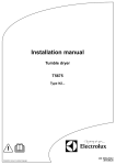
Installation manual
Tumble dryer
T5290
Type N2...
Installation manual in original language
438 9054-00/EN
2011.09.12
Contents
Contents
1 Safety Precautions ............................................................................................................. 5
2 Technical data .................................................................................................................... 7
2.1 Drawing ...................................................................................................................... 7
2.2 Technical data............................................................................................................. 8
2.3 Connections................................................................................................................ 8
3 Setup.................................................................................................................................. 9
3.1 Unpacking................................................................................................................... 9
3.2 Siting........................................................................................................................... 10
3.3 Mechanical installation ............................................................................................... 10
4 Marine installation .............................................................................................................. 11
5 Reversing the door............................................................................................................. 12
6 Evacuation system ............................................................................................................. 15
6.1 Air principle................................................................................................................. 15
6.2 Fresh air ..................................................................................................................... 16
6.3 Exhaust duct............................................................................................................... 17
6.4 Shared exhaust duct................................................................................................... 18
6.5 Exhaust dimensioning ................................................................................................ 19
7 Steam connection .............................................................................................................. 20
7.1 Connecting the steam................................................................................................. 20
7.2 Steam calorifier........................................................................................................... 21
8 Gas connection .................................................................................................................. 23
8.1 Fasten the label .......................................................................................................... 23
8.2 General....................................................................................................................... 23
8.3 Gas installation ........................................................................................................... 24
8.4 Table of pressure and adjustment .............................................................................. 25
8.5 Test run....................................................................................................................... 26
8.6 Converting instructions ............................................................................................... 27
8.7 Data label ................................................................................................................... 29
9 Electrical connection .......................................................................................................... 30
9.1 Electrical installation ................................................................................................... 30
9.2 Single-phase connection ............................................................................................ 31
9.3 Three-phase connection............................................................................................. 32
9.4 Electrical connections................................................................................................. 33
9.5 Functions for I/O-cards ............................................................................................... 34
9.5.1 Central payment (22J) ........................................................................................ 34
9.5.2 Central payment (22J) ........................................................................................ 35
9.5.3 External coin meter/Central payment (22K)........................................................ 36
9.5.4 Price reduction (22K) .......................................................................................... 37
9.5 Option ......................................................................................................................... 38
9.5.1 External connection 100 mA ............................................................................... 38
10 Function check ................................................................................................................. 39
The manufacturer reserves the right to make changes to design and component specifications.
Safety Precautions
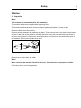
1 Safety Precautions
The machine is not intended for use by persons (including children) with reduced physical, sensory or
mental capabilities, or lack of experience and knowledge, unless they have been given supervision or
instruction concerning use of the appliance by a person responsible for their safety.
Children should be supervised to ensure that they do not play with the machine.
The machine is not to be used if industrial chemicals have been used for cleaning.
Do not dry unwashed items in the machine.
Items that have been soiled with substances such as cooking oil, acetone, alcohol, petrol, kerosene, spot
removers, turpentine, waxes and wax removers should be washed in hot water with an extra amount
of detergent before being dried in the machine.
Items such as foam rubber (latex foam), shower caps, waterproof textiles, rubber backed articles and
clothes or pillows fitted with foam rubber pads should not be dried in the machine.
Fabric softeners or similar products should be used as specified by the fabric softener instructions.
The final part of a drying cycle occurs without heat (cool down cycle) to ensure that the items are left at a
temperature that ensures that the items will not be damaged.
Remove all objects from pockets such as lighters and matches.
WARNING. Never stop the machine before the end of the drying cycle unless all items are quickly removed
and spread out so that the heat is dissipated.
Adequate ventilation has to be provided to avoid the back flow of gases into the room for appliances
burning other fuels, including open fires.
Exhaust air must not be discharged into a flue which is used for exhausting fumes from appliances burning
gas or other fuels.
The machine must not be installed behind a lockable door, a sliding door or a door with a hinge on the
opposite side to that of the machine.
If the machine has a lint trap this has to be cleaned frequently.
The lint must not be accumulated around the machine.
Gas heated tumble dryer:
The machine is not to be installed in rooms containing cleaning machines with perchloroethylene,
TRICHLOROETHYLENE or CHLOROFLUOROCONTAINING HYDROCARBONS as cleaning agents.
If you can smell gas:
• Do not switch on any equipment
• Do not use electrical switches
• Do not use telephones in the building
• Evacuate the room, building or area
• Contact the person responsible for the machine
All external equipment which is connected to the machine must be CE/EMC-approved and connected using
an approved shielded cable.
5
6
Safety Precautions
In order to prevent damage to the electronics (and other parts) that may occur as the result of condensation,
the machine should be placed in room temperature for 24 hours before being used for the first time.
Technical data
7
2 Technical data
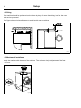
2.1 Drawing
B(b)
B(a)
A
H
1
K
3
L
3
4
7
7
N
C
6
2
J
G
6
D E
5
5
I
F
1
Operating panel
2
Door opening, ⌀ 580 mm
3
Electrical connection
4
Gas connection
5
Exhaust connection
6
Steam: in
7
Steam: out
mm
mm
A
B(a)
B(b)
C
D
E
F
G
710
1155
1335
1675
725
780
140
1310
H
I
J
K
L
M
N
70
155
1380
55
355
685
605
M
8
Technical data
2.2 Technical data
Weight, net
kg
220
litres
290
Drum diameter
mm
680
Drum depth
mm
770
Drum speed
rpm
50
Drum volume
0.94
G-factor, max.
Capacity, filling factor 1:18 (Max. load)
kg
16.1
Capacity, filling factor 1:22 (Recommended. load)
kg
13.2
kW
18
kW
13.5
Heating: Gas
kW
21
Heating: Steam
kW
25
Air consumption, Electric heating, 13.5 kW
m3/h
380
Air consumption, Electric heating, 18.0 kW
m3/h
450
Air consumption, Gas heating
m3/h
550
Air consumption, Steam heating
m3/h
640
dB(A)
70
Pressure drop, Electric heating, 13.5 kW
Max. Pa
400
Pressure drop, Electric heating, 18.0 kW
Max. Pa
350
Pressure drop, Gas heating
Max. Pa
350
Pressure drop, Steam heating
Max. Pa
350
⌀ mm
200
Heating: Electricity
Airborne sound level
2.3 Connections
Air outlet
Steam outlet
Condensate outlet
Gas connection
1”
ISO 7/1–Rp1/2
-
ISO 7/1–Rp1/2
1/2”
ISO 7/1–R1/2
Setup
3 Setup
3.1 Unpacking
Note!
Two persons are recommended for the unpacking.
The machine is delivered complete with supporting feet.
The machine is delivered bolted onto the transport pallet and packed in a crate or box.
Remove packing from the machine.
Remove the bolts between the machine and pallet. There are two bolts in the front of the machine
and two in the back of the machine. Remove the lower front panel and remove the two bolts in
the front of the machine. Remove the lower back panel and remove the two bolts in the back of
the machine. Remount the panels when done.
fig.7189A
①
Remove the machine from the pallet.
Note!
When removing the machine, handle it with care. The drum has no transport securities.
Place the machine on its final position.
9
Setup
10
3.2 Siting
The machine should be positioned so that there is plenty of room for working, both for the user
and service personnel.
The figure shows minimum distance to a wall and/or other machines.
Max. 50 mm /
1 15/16 inch
500 mm /
20 inch
10 mm /
3/8 inch
10 mm /
3/8 inch
Min.150 mm / 5 7/8 inch
Min. 20 mm /
13/16 inch
fig.7187
②
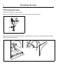
3.3 Mechanical installation
Level the machine with the feet of the machine. The maximum height adjustment of the feet
is 15 mm.
fig.7188
③
Marine installation
11
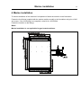
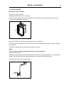
4 Marine installation
To ensure steadiness of the machine it is important to fasten the machine to the foundation.
Fasten the four fittings (supplied with the marine machine model) to the foundation using four x M10
set screws. If the four fittings is not supplied, order kit Nr. 487193544.
Fasten the machine to the fittings.
Note!
Marine installation is not applicable for gas heated machines.
1005.6 mm / 39 5/8 inch
M10
73 mm / 2 7/8 inch
43.3 mm / 1 11/16 inch
1065 mm / 41 15/16 inch
15.3 mm / 9/16 inch
677.1 mm / 26 5/8 inch
617.6 mm / 24 5/16 inch
45 mm / 1 3/4 inch
④
12
Reversing the door
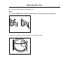
5 Reversing the door
Disconnect the power to the machine.
Demount the hinges and remove the door. Remove the upper hinge first.
fig.7166
⑤
Remove the screws on the front panel and carefully loosen the panel. Disconnect the door switch
cable and remove the panel.
fig.7179A
⑥
Reversing the door
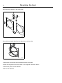
Move the door switch cable to the opposite site.
Note!
The plastic plug MUST be placed in the hole where the door switch cable was before.
fig.7170
⑦
Loosen the nuts and move the two brackets to the opposite side.
fig.7171
⑧
13
Reversing the door
14
Move the door switch on the front panel.
2
3
1
4
fig.7172
⑨
Move the four metal clips from the right side to the left side.
fig.7174
⑩
Connect the door switch cable and remount the front panel.
Fasten the hinges and mount the door on the opposite side than before.
Connect the power to the machine.
Test run the machine.
Evacuation system
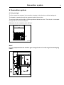
6 Evacuation system
6.1 Air principle
The fan creates low pressure in the machine, drawing air into the drum via the heating unit.
The heated air passes through the garments and the drum holes.
The air then flows outh through a lint filter positioned below the drum. Then the air is evacuated
through the fan and exhaust system.
Dimension for air evacuation (A) is 200 mm.
A
fig.W00264
⑪
Note!
It is very important that the machine gets enough fresh air in order to get the best drying
result.
⑫
15
Evacuation system
16
6.2 Fresh air
For maximum efficiency and the shortest possible drying time, it is important to ensure that fresh air
is able to enter the room from the outside in the same volume as that blown out of the room
To avoid draught in the room it is important to place the air inlet behind the machine.
The area of the air inlet opening must be five times the size of the exhaust pipe area. The
area of the inlet opening is the area through which the air can flow without resistance from the
grating/slatted cover.
A
5x A
fig.7183
⑬
Note!
Gratings/slatted covers often block half of the total fresh air vent area. Remember to take
this into account.
Evacuation system
6.3 Exhaust duct
• Only rigid or flexible metal duct should be used for exhausting.
• Plastic ducting is not to be used.
• Recommended material for exhaust is galvanised steel.
• The duct is not to be assembled with screws of other fastening means that extend into the
duct and catch lint.
• The exhaust air should not be vented into a wall, a ceiling, or a concealed space of building.
• The exhaust duct must lead clear of the building as condensation may cause frost damage
to the building.
• The exhaust duct must lead to the outdoors.
• The exhaust duct must be placed in such a way that it is protected on the outside.
• The exhaust duct must be smooth on the inside (low air resistance).
• The exhaust duct must have gentle bends.
• The exhaust duct must not be a shared duct between machines and appliances using gas or
other fuels as their energy source.
⑭
17
Evacuation system
18
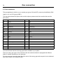
6.4 Shared exhaust duct
It is recommended that each machine is connected to a separate exhaust duct.
When several machines shall use the same exhaust duct the exhaust duct must increase after
each machine.
⑮
1
2
3
4
5
6
7
8
9
10
Exhaust duct ⌀ mm
200
280
315
355
400
450
475
500
535
560
Minimum area of fresh-air intake
m2
0.15
0.30
0.45
0.60
0.75
0.90
1.05
1.20
1.35
1.50
Number of machines
The exhaust duct diameter must not be reduced.
Evacuation system
6.5 Exhaust dimensioning
It is important that the machine has correct air volume compared to each machines power.
If the air volume is smaller or bigger this will result in a longer drying period.
The machine is designed to work with 25 m outlet pipe and two 90 degree bends. Each bend is
equal to 2.5 m. If more than two bends is needed the length should maximum be shortened with
2.5 m per bend.
If the outlet pipe is longer or the ventilation is not properly designed we recommend to clean the
outlet pipes periodically.
The exhaust pipes shall be short in order for the machine to work in the best way.
All cover plates must be mounted in order for the machine to work in the best way.
19
Steam connection
20
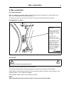
7 Steam connection
7.1 Connecting the steam
Note!
The steam pipe must be cut off and must not be under pressure.
• The branch pipe’s must be located at the top of the main steam pipe to prevent condensation in
the steam.
• The branch pipe must have a descending gradient and must end at a height above the inlet
connecting branch (5). For measurements M, N and O, please refer to the dimension drawing.
• Mount a plug valve (a) and a dirt collector (c) in the brach pipe.
a
b
5
N
6
b
c
a
M
L
fig.7194
⑯
Condensate return
It is important that the brach pipe for condensed water on return to the main condensate pipe has a
descending gradient and is lower than the outlet connecting branch (6).
• Mount a dirt collector (b) in the return pipe.
• Mount a mechanical water discharger behind the dirt collector (c).
• Mount a plug valve (a).
• Mount pressure hoses between the branch pipes and the machine. Note that hoses are not
supplied.
Pipe insulation
All pipes must be insulated in order to reduce risk of burning. Insulation also reduces loss of heat
to the surroundings.
Steam connection
21
7.2 Steam calorifier
Mount the steam calorifier
Unpack the steam calorifier.
Demount the back plate on the machine.
Demount the supporting rail on the machine (A). Note which way the supporting rail turns as it
has to be remounted the same way.
A
⑰
Hang the calorifier on the bottom supporting rail on the machine.
Hold the calorifier towards the machine and remount the supporting rail. Make sure that it grasps
the calorifier.
Fasten the calorifier into the supporting rail with the screws.
Note!
There must be no space between the machine and the calorifier.
Mount the back plate.
Attatch the pressure hoses to the machines inlet and outlet connecting branches. It is important to
support the inlet and the outlet connecting brances in order to prevent deformation.
The pressure hoses must not hang down.
fig.7195
⑱
22
When ready
Leak test the system.
Clean the dirt collectors.
Perform a function chek.
Steam connection
Gas connection
23
8 Gas connection
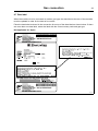
8.1 Fasten the label
Before installing the machine fasten the label “Read the user instructions” on the inside of the
door in a suitable place and at the front panel.
The label must have the correct country code, choose the correct label from the gas kit.
Not applicable for Japan.
GB, IE
Read the tec hnica l
ins tructions be fore
ins ta lling the a pplianc e .
, IE
ic a l
GB
chn
e te fo re
d th s b e
R e a u c tio n e a p p liin s tr llin g th
in s ta .
e
a nc
er
e u s fo re
d th s b e n c e .
R e a u c tio n a p p lia
in s tr n g th e
ti
ay
lig h
c e min a
lia n
a p p ta lle d
Th is b e in s ro o m a te
ri
o n ly if th e p p ro p
a
m
ro o ts th e q u ire th e
re
m e e la tio n ifie d inn
ti
c
ve n ts s p e ta lla tio
s
m e n n a l in .
o
n a ti la tio n s
.....
u
......
re g
No .
Art.
Read the us e r
ins tructions be fore
lighting the a pplia nce .
This a pplia nce ma y
only be ins ta lle d in a
room if the room
me e ts the a ppropria te
ve ntila tion re quire me nts s pe cifie d in the
nati onal ins ta lla tion
regul ations .
Art. No. ...........
fig.7113
⑲
8.2 General
May only be carried out by qualified personnel.
Mount a shut-off valve upstream from the machine.
The factory nozzle pressure setting corresponds to the fuel value given on the data label.
Check that the nozzle pressure and fuel value correspond with the values in the gas tables on the
following pages. If not, contact the supplier.
Bleed the pipe system before connecting the machine.
Note!
After connection all joints must be checked. There must not be any leaks.
Gas connection
24
8.3 Gas installation
This gas appliance is build to run on natural gas (group I2H and I2E), commonly identified by GNH.
Japan to run on LPG (group I3B/P).
The data label shows the injector size and the injector pressure and the countries that use this
gas quality:
AL
Albania
IS
Iceland
AT
Austria
IT
Italy
BE
Belgium
JP
Japan
BG
Bulgaria
LT
Lithuania
CH
Switzerland
LU
Luxembourg
CY
Cyprus
LV
Latvia
CZ
Czech Republic
MK
Republic of Macedonia
DE
Germany
MT
Malta
DK
Denmark
NL
Netherlands
EE
Estonia
NEC
Non-european countries
ES
Spain
NO
Norway
FI
Finland
PL
Poland
FR
France
PT
Portugal
GB
United Kingdom
RO
Romania
GR
Greece
SE
Sweden
HR
Croatia
SI
Slovenia
HU
Hungary
SK
Slovakia
IE
Ireland
TR
Turkey
You should check the kind of energy gas that is available in your place.
There are many gas types of the same kind but the machine should be equipped with different
kinds of nozzles depending on the gas type.
For non-european countries check the heat value of the energy gas and compare it to the delcared
heat value of gas in the attached label.
Gas connection
25
8.4 Table of pressure and adjustment
Liquied
petroleum
gases
Gas
category
Inlet
pressure
(mbar)
Burner
pressure
(mbar)
Injector size
(mm)
Butane
I3B/P
30, 37 or 50
28
Propane
I3P
30, 37 or 50
Propan
and butane
mixture
I3+
Natural gas
Air reducing
plate (mm)
Label
number
May be
available
in following
countries
2.3
490375644
BE, CY, DK,
EE, FR, GB,
HU, IT, LT,
NL, NO, SE,
SI, SK, RO,
HR, TR, BG,
IS, LU, MT,
AT, CH, DE
28
2.4
490375645
FI, NL, RO,
BE, CH, CZ,
IE, IT, ES,
FR, GR, GB,
HR, LT, NL,
PT, SI, SK,
AT, DE, LU
28-30 for
butane
and 37 for
Propane
No
regulation
2.3
490375643
BE, CH, CY,
CZ, ES, FR,
GB, GR, IE,
IT, LT, LU,
LV, PT, SK,
SI
Gas
category
Inlet
pressure
(mbar)
Burner
pressure
(mbar)
Injector size
(mm)
Label
number
May be
available
in following
countries
I2H, I2E
20
8
4.0
490375646
AT, BG, CZ,
DK, EE, FI,
GR, HR, HU,
IS, IE, IT, LV,
LT, NO, PT,
RO, SK, SI,
ES, SE, CH,
TR, GB, DE,
PL, LU
I2L, I2LL
25, 20
12
4.0
490375642
NL, DE
I2E+
20 or 25
No
regulation
3.3
490375641
BE, FR
Air reducing
plate (mm)
Gas connection
26
8.5 Test run
Loose the pressure measuring tap screw (2) 1/4 of a turn.
Connect a manometer to the measuring tap.
Select a program that uses heat.
Start the machine.
Check the nozzle pressure, see table.
If necessary adjust the regulator setting screw (4) behind the cover screw (3). Replace the cover
screw (3) if removed.
Check that the gas is burning evenly.
2
3, 4
fig.7120
⑳
Gas connection
27
8.6 Converting instructions
Not applicable for Japan.
Disconnect the power to the machine.
Demount the lower back panel.
Remove the nozzle (1).
Mount the new supplied nozzle.
1
fig.7127
21
Loosen the measuring branch screw (2) 1/4 turn; connect a manometer to the measuring branch.
Connect the power to the machine and select a program with heat.
Start the machine.
Set the correct nozzle pressure according to the table on setting screw (4) under the cover screw (3).
2
3, 4
fig.7120
22
28
Gas connection
Check that the gas flame burns evenly.
Mount the cover screw (3).
Remount the lower back panel.
Gas connection
29
8.7 Data label
When the machine is to be converted to another gas type, the data label at the rear of the machine
must be updated in order for the data to be correct.
Place the data label enclosed in the conversion kit on top of the data label as shown below. If there
are more than one data label, select the label with the correct country code and gas type.
Not applicable for Japan.
Product no.:
Serial no.:
OC:
Program:
Typ e :
WXXXXX
9868XXXXXX
09XXX / 99XXXXX
09XXXXXX
10XX
432XXXXXX,5XXX
432XXXXXXXX
WN3...WN3XXXX
Vo lta g e :
WXXXXX
9868XXXXXX
09XXX / 99XXXXX
Date(YYMM): 10XX
09XXXXXX
X kg
WN3...WN3XXXX
380 400V
3N
50Hz
Rated Input:
1,6kW
Product no.:
Serial no.:
OC number:
Capacity:
Typ e /Mo d e l:
~
DK,NO,SE,FI,GB,ES,GR,I E,IT,P T,AT: 12H-20 MBAR
DE: 12E( LL)-20MBAR
ID.nr. 359BQ491
MANIF. PRESSURE : 10 M BAR. INJ ECTOR. Ø3,10 MM
NATURAL GAS : G20-20 MBAR
(INLET P RES : 20 MBAR, CAL. VAL. 37400 KJ /M3)
Art. No. ..........
10A
DK,NO,SE,FI,CH,CZ,EE,L T,S I,TR,BG,RO : I2H
GB,ES,GR,IE,IT ,PT,AT,LV,HU,IS ,S K : I2H
DE,PL,LU : I2E(LL)
PIN No 359BS703
MANIF. PRESSURE : 9 MBAR. INJECT OR: Ø2,58 MM
NATURAL GAS : G20
IP 24D
(INLET PRES: 20 MBAR, CAL. V AL. 37400 KJ/M3)
For safety reasons use only genuine spar
e par ts.
Mad e in S we d e n
Ele ctrolux La undry S ys te ms AB
341 80 Ljungby, S we de n.
Product no.:
Serial no.:
OC:
Program:
Typ e :
WXXXXX
9868XXXXXX
09XXX / 99XXXXX
09XXXXXX
10XX
432XXXXXX,5XXX
432XXXXXXXX
WN3...WN3XXXX
fig.7110
23
30
Electrical connection
9 Electrical connection
9.1 Electrical installation
The electrical installation may only be carried out by qualified personnel.
Machines with frequency-controlled motors can be incompatible with certain types of earth leakage circuit
breaker. It is important to know that the machines are designed to provide a high level of personal safety,
which is why items of external equipment such as earth leakage circuit breakers are not necessary. If you
still want to connect your machine across an earth leakage circuit breaker, please remember the following:
• contact a skilled, authorised installation company to ensure that the appropriate type of breaker is chosen
and that the dimensioning is correct
• for maximum reliability, connect only one machine per earth leakage circuit breaker
• it is important that the earth wire is properly connected, including to the earth leakage circuit breaker.
In instances where the machine is not equipped with an omni-polar switch, one must be installed
beforehand.
Mount a multi-pole switch prior to the machine to facilitate installation and service operations.
The connecting cable should hang in a gentle curve.
Fuse size, see table.
Electrical connection
9.2 Single-phase connection
Demount the cover plate from the supply unit. Connect the earth and other wires as shown.
1NAC
1AC
1AC
L1
L2/N
When the installation is completed remount the cover plate and check:
• that the drum is empty.
• that the machine operates by turning on the mains switch and start a program with heat.
31
Electrical connection
32
9.3 Three-phase connection
Demount the cover plate from the supply unit. Connect the earth and other wires as shown.
3AC
3AC
L1
L2
L3
L1
L2
L3
3NAC
3NAC
N
When the installation is completed remount the cover plate and check:
• that the drum is empty.
• that the machine operates by turning on the mains switch and start a program with heat.
Electrical connection
33
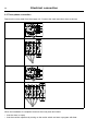
9.4 Electrical connections
Heating
alternative
Main voltage
Electric heating
Gas
heating/Steam
heating
Hz
Heating power
kW
Total power
kW
Recommended
fuse
A
400–415V 3N ~
50/60
13.5
14.5
25
400–415V 3N ~
50/60
18.0
18.9
35
440–480V 3 ~
60
13.5
14.5
20
440–480V 3 ~
60
18.0
19.0
35
230–240V 3 ~
50/60
18.0
19.0
50
230–240V 3 ~
50/60
13.5
14.5
50
230–240V 1 ~
50/60
13.5
14.3
63
230–240V 1 ~
50/60
18.0
18.8
100
200V 3N ~
50/60
13.5
14.4
50
200V 3N ~
50/60
18.0
18.8
63
400–415V 3N ~
50/60
-
1.0
10
60
-
1.0
10
50/60
-
1.0
10
230–240V 1 ~
50/60
-
1.0
10
200V 3N ~
50/60
-
0.9
10
440–480V 3 ~
230–240V 3 ~
34
Electrical connection
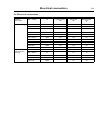
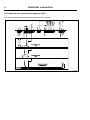
9.5 Functions for I/O-cards
The electrical schematic can be one of the following:
9.5.1 Central payment (22J)
To start the machine from a central payment system, the payment system must transmit a start
pulse to the machine. The start pulse can be either 230V or 24V. In order to receive a feedback
signal once the machine has started, 230V or 24V must be connected to connection 19. The
feedback signal on connection 18 remains active (high) during the entire program.
fig.7440
24
Electrical connection
35
9.5.2 Central payment (22J)
P rogra m run
The central payment or booking system shall transmit an active (high) signal to the machine once
permission has been granted to start the machine. The signal must remain active (high) until the
machine starts. The signal can be either 230V or 24V. In order to receive a feedback signal once
the machine has started, 230V or 24V must be connected to connection 19. The feedback signal
remains active (high) during the entire program.
fig.7439
25
36
Electrical connection
9.5.3 External coin meter/Central payment (22K)
The signal received from external coin meters must be a pulse.
fig.7438
26
Electrical connection
37
9.5.4 Price reduction (22K)
By maintaining an activated (high) signal on connection 5 ("Price red"), the price of the program can
be reduced. This function has a number of uses, including providing reductions during a specific
period of the day. Whilst the signal remains active (high), the price of the program is reduced by the
percentage entered in the price programming menu.
fig.7441
27
Electrical connection
38
9.5 Option
9.5.1 External connection 100 mA
A special connection terminal is located on the connection console.
This connection can be used as external control of a fan.
The terminal for external control is equipped with 220–240V max.100 mA and is intended solely for
the operation of a contactor
Max. connection 100 mA.
Gnd. must not be used for earthing of external board.
X1
X2 Gnd.
fig.7154
28
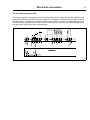
Function check
10 Function check
May only be carried out by qualified personnel.
A function check must be made when the installation is finished and before the machine can be
used.
Check the automatic stop of the machine
• Start the machine.
• Check if the micro switches are working properly:
The machine must stop if the door is opened.
Check the direction of rotation (only on machines with 3–phase power supply)
• Demount the lower back panel of the machine.
• Check that the direction of the fan wheel is correct.
fig.7118
29
39
40
Function check
If the direction is wrong, swop two of the three phases to the left on the connection terminal.
fig.7119
30
Check the heat
• Let the machine work for five minutes on a program with heat.
• Check that the heating is working by opening the door and feel if there is heat in the drum.
Ready to use
If all tests are OK the machine is now ready to be used.
If some of the tests failed, or deficiencies or errors are detected, please contact your local service
organisation or dealer.
Washer extractors, Tumble dryers, Hydro extractors
Types: W.55H., W3..., WN3..., W4.H., EXSM.X., H1..., N1130.., N1190.., N2..., N3..., N4..., N5...
Product standards:EN 60335-2-4, -7, -11
EMF standards:
EN 50366:2003 + A1
EMC standards:
EN 61000-6-1 (2001) W.55H., W3..., W4.H., N1130, N1190, N2..., N3...
EN 61000-6-3 (2001) W.55H., W3..., WN3..., W4.H., EXSM.X., N1130, N1190, N2..., N3...
A11 (2003) WN3..., N5...
EN 61000-3-11 (2001) EXSM.X.
EN 61000-6-2 (2005) WN3..., N4..., N5...
EN 61000-6-3 (2007) N4...
Försäkran om överensstämmelse
EF-samsvarserklæring
Vi,
Electrolux Laundry Systems Sweden AB
SE-341 80 Ljungby, Sverige
försäkrar under eget ansvar att denna produkt, med typbeteckning och enl. ovan, är tillverkad i
överensstämmelse med följande direktiv:
• LVD Directive 2006/95/EC
• EMC Directive 2004/108/EC
• GAS Directive 2009/142/EC (gäller endast N'''''' och WN3...)
• CE Marking Directive 93/68/EEC
• RoHS Directive 2002/95/EC
• WEEE Directive 2002/96/EC
• MD Directive 2006/42/EC
Vi,
Electrolux Laundry Systems Sweden AB
SE-341 80 Ljungby, Sverige,
erklærer på eget ansvar at dette produktet, med typebetegnelse og produksjonsnummer som
angitt nedenfor, er produsert i samsvar med bestemmelsene i følgende direktiver:
• LVD Directive 2006/95/EC
• EMC Directive 2004/108/EC
• GAS Directive 2009/142/EC (gjelder bare N'''''' og WN3... )
• CE Marking Directive 93/68/EEC
• RoHS Directive 2002/95/EC
• WEEE Directive 2002/96/EC
• MD Directive 2006/42/EC
CE Declaration of conformity
EG-Conformiteitsverklaring
We,
Electrolux Laundry Systems Sweden AB
SE-341 80 Ljungby, Sweden
declare under our sole responsibility that the product of the type stated above is manufactured in
conformity with the following EU directives:
Wij,
Electrolux Laundry Systems Sweden AB
SE-341 80 Ljungby, Zweden
verklaren hierbij op eigen verantwoordelijkheid dat het produkt van het type en met het serienummer zoals hieronder vermeld, is vervaardigd conform de volgende normen:
• LVD Directive 2006/95/EC
• EMC Directive 2004/108/EC
• GAS Directive 2009/142/EC (alleen N'''''' en WN3...)
• CE Marking Directive 93/68/EEC
• RoHS Directive 2002/95/EC
• WEEE Directive 2002/96/EC
• MD Directive 2006/42/EC
•
•
•
•
•
•
•
LVD Directive 2006/95/EC
EMC Directive 2004/108/EC
GAS Directive 2009/142/EC (N''''''... and WN3... only)
CE Marking Directive 93/68/EEC
RoHS Directive 2002/95/EC
WEEE Directive 2002/96/EC
MD Directive 2006/42/EC
EG-Konformitätserklärung
Wir, die, Electrolux Laundry Systems Sweden AB
SE-341 80 Ljungby, Schweden
erklären hiermit in alleiniger Verantwortung, daß das Produkt mit der oben genannten Typenbezeichnung mit folgenden EU-Richtlinien übereinstimmt:
•
•
•
•
•
•
•
LVD Directive 2006/95/EC
EMC Directive 2004/108/EC
GAS Directive 2009/142/EC (Nur N'''''' und WN3...)
CE Marking Directive 93/68/EEC
RoHS Directive 2002/95/EC
WEEE Directive 2002/96/EC
MD Directive 2006/42/EC
Déclaration de conformité CE Nous,
Electrolux Laundry Systems Sweden AB
SE-341 80 Ljungby, Suède
déclarons sous notre seule et unique responsabilité que le produit des type et numéro de série
indiqués ci-dessus est fabriqué conformément aux directives UE suivantes:
•
•
•
•
•
•
•
LVD Directive 2006/95/EC
EMC Directive 2004/108/EC
GAS Directive 2009/142/EC (N'''''' et WN3... uniquement)
CE Marking Directive 93/68/EEC
RoHS Directive 2002/95/EC
WEEE Directive 2002/96/EC
MD Directive 2006/42/EC
Declaración de conformidad CE
Electrolux Laundry Systems Sweden AB
con sede en SE-341 80 Ljungby, Suecia
declara bajo su exclusiva responsabilidad que el producto cuyo tipo se especifica en el
encabezado se ha fabricado conforme a las siguientes directivas:
•
•
•
•
•
•
•
LVD Directive 2006/95/EC
EMC Directive 2004/108/EC
GAS Directive 2009/142/EC (vale sólo N'''''' y WN3)
CE Marking Directive 93/68/EEC RoHS Directive 2002/95/EC
WEEE Directive 2002/96/EC
MD Directive 2006/42/EC
Erklæring om EU-overensstemmelse
Vi
Electrolux Laundry Systems Sweden AB
SE-341 80 Ljungby, Sverige
erklærer på eget ansvar, at produktet med typebetegnelse som angivet er fremstillet i overens
stemmelse med følgende EU-direktiver:
•
•
•
•
•
•
•
LVD Directive 2006/95/EC
EMC Directive 2004/108/EC
GAS Directive 2009/142/EC (gælder kun N'''''' og WN3...)
CE Marking Directive 93/68/EEC
RoHS Directive 2002/95/EC
WEEE Directive 2002/96/EC
MD Directive 2006/42/EC
Dichiarazione CE di conformità
Noi
Electrolux Laundry Systems Sweden AB
SE-341 80 Ljungby, Svezia
dichiariamo sotto la nostra esclusiva responsabilità che il prodotto del tipo specificato sopra è
conforme alle seguenti direttive [UE]:
• LVD Directive 2006/95/EC
• EMC Directive 2004/108/EC
• GAS Directive 2009/142/EC (solo N'''''' e WN3...)
• CE Marking Directive 93/68/EEC
• RoHS Directive 2002/95/EC
• WEEE Directive 2002/96/EC
• MD Directive 2006/42/EC
Declaração CE de conformidade
Nós,
Electrolux Laundry Systems Sweden AB
SE-341 80 Ljungby, Suécia
declaramos sob nossa inteira responsabilidade que o produto com os números de série e de tipo
abaixo indicados é fabricado em conformidade com as seguintes directivas [UE]:
• LVD Directive 2006/95/EC
• EMC Directive 2004/108/EC
• GAS Directive 2009/142/EC (apenas N'''''' e WN3...)
• CE Marking Directive 93/68/EEC
• RoHS Directive 2002/95/EC
• WEEE Directive 2002/96/EC
• MD Directive 2006/42/EC
ΔΗΛΩΣΗ ΠΙΣΤΟΤΗΤΑΣ ΕΚ
H
Electrolux Laundry Systems Sweden AB
SE-341 80 Ljungby, Σουηδία
δηλώνει με αποκλειστική της ευθύνη ότι το προϊόν του ανωτέρω αναφερόμενου τύπου
κατασκευάζεται σύμφωνα με τις ακόλουθες οδηγίες της Ευρωπαϊκής Ένωσης:
• LVD Directive 2006/95/EC
• EMC Directive 2004/108/EC
• GAS Directive 2009/142/EC (N'''''' και WN3... μόνο)
• CE Marking Directive 93/68/EEC
• RoHS Directive 2002/95/EC
• WEEE Directive 2002/96/EC
• MD Directive 2006/42/EC
CE megfelelöségi nyilatkozat
Mi, az
Electrolux Laundry Systems Sweden AB
SE-341 8 Ljungby, Svédország
felelöségünk teljes tudatában kijelentjük, hogy az alább megadott típusú termék gyártása a
következö EU-irányelvekkel összhangban történik:
• LVD Directive 2006/95/EC
• EMC Directive 2004/108/EC
• GAS Directive 2009/142/EC (csak az N'''''' és WN3... esetén)
• CE Marking Directive 93/68/EEC
• RoHS Directive 2002/95/EC
• WEEE Directive 2002/96/EC
• MD Directive 2006/42/EC
Ljungby 2011.06.21
EY-Vaatimustenmukaisuusvakuutus
Me
Electrolux Laundry Systems Sweden AB
SE-341 80 Ljungby, Ruotsi
vakuutamme yksinomaan omalla vastuullamme, että tuote, jonka tyyppitunnus lukee yllä, on valmistettu seuraavien [EU]-direktiivien mukaisesti:
•
•
•
•
•
•
•
LVD Directive 2006/95/EC
EMC Directive 2004/108/EC
GAS Directive 2009/142/EC (vain N'''''' ja WN3...)
CE Marking Directive 93/68/EEC
RoHS Directive 2002/95/EC
WEEE Directive 2002/96/EC
MD Directive 2006/42/EC
Franco Panno
Vice President Technical Operations
471 1531-43/21
Page 1/2
Translation table for model name to type of approval
Commercial name
Type
Commercial name
Type
W455H
W.55H.
T4300S
N3...
W465H
W3...
T4290
N4...
W475H
W3...
T4530
N4...
W4105H
W3...
T4650
N4...
W4130H
W3...
T4900
N4...
W4180H
W3...
T41200
N4...
W4240H
W3...
T4900CR
N4...
W4300H
W3...
T41200CR
N4...
FOM71 CLS
W3...
T4300LE
N5...
WB4130H
W3...
WB4180H
W3...
PW9
W3...
W475S
W3...
W485S
W3...
W4105S
W3...
W4130S
W3...
W4180S
W3...
W4250S
W3...
W4330S
W3...
W475N
W3...
W485N
W3...
W4105N
W3...
W4130N
W3...
W4180N
W3...
W4250N
W3...
W4330N
W3...
WD4130H
WN3...
WD4240H
WN3...
W4400H
W4.H.
W4600H
W4.H.
W4850H
W4.H.
W41100H
W4.H.
W4280X
EXSM.X.
W4350X
EXSM.X.
W4600X
EXSM.X.
C240
H1...
C260
H1...
C240R
H1...
C260R
H1...
C290R
H1...
T4130
N1130..
T4190
N1190..
PD9
N1190..
T4250
N2...
T4350
N2...
T5290
N2...
T5550
N2...
T5675
N2...
Ljungby 2011.06.21
Franco Panno
Vice President Technical Operations
471 1531-43/21
Page 2/2
Skrotning av maskin
När maskinen inte längre skall användas måste den lämnas till en återvinningsstation för destruktion. Många detaljer i maskinen går att återanvända,
men den innehåller även annat material som måste tas om hand på ett korrekt sätt. Lämna därför aldrig maskinen eller delar av maskinen i
hushållsavfallet, eftersom det kan leda till hälsorisker eller skador på miljön.
Scrapping of machine
When the machine is no longer to be used, it must be submitted to a recycling facility for destruction. The majority of the components in the machine
can be reused, but it also contains other material that must be taken care of in the correct way. Therefore, never mix the machine or its parts with
domestic waste as this may lead to health hazards or damage to the environment.
Entsorgung des Geräts
Wenn das Gerät nicht länger im Gebrauch ist, muss dieses einer Recyclingstation zur Entsorgung zugeführt werden. Viele Komponenten des Geräts
sind recyclingfähig, enthalten aber auch Materialien, die vorschriftsmäßig entsorgt werden müssen. Entsorgen Sie daher das Gerät oder Geräteteile
niemals im Hausmüll, da dies Gefahren für die Gesundheit oder Umweltschäden nach sich ziehen kann.
Mise au rebut de machine
Lorsque la machine n’est plus utilisée, elle doit être déposée à une installation de recyclage pour y être détruite. La majorité des composants de la
machine peuvent être réutilisés mais celle-ci contient également d’autres matériaux qui doivent être traités correctement. C’est pourquoi vous ne
devez jamais mélanger la machine ou ses pièces avec les ordures ménagères, risque de polution pour l’environnement ou la santé.
Desguace de la máquina
Cuando la máquina no tenga que utilizarse más, ha de entregarse a una instalación de destrucción para su reciclado. La mayor parte de sus
componentes pueden volver a utilizarse, pero consta también de otros materiales que han de ser tratados de la manera correcta. Por esa razón
nunca mezclar la máquina ni sus partes con la basura doméstica pues esto podría constituir un peligro para la salud o dañar el medio ambiente.
Bortskaffelse af maskinen
Når maskinen ikke længere er i brug, skal den afleveres til destruktion på en genbrugsstation. Mange dele i maskinen kan genanvendes, men den
indeholder også andre materialer, der skal håndteres korrekt. Smid derfor ikke maskinen eller dele af den ud sammen med husholdningens
almindelige affald, da det kan være forbundet med sundhedsrisiko eller give miljøskader.
Koneen hävittäminen
Kun konetta ei enää käytetä, se pitää luovuttaa kierrätyskeskukseen tuhottavaksi. Suurinta osaa koneen osista voidaan käyttää uudelleen, mutta se
sisältää myös materiaaleja, jotka pitää käsitellä asianmukaisesti. Älä sen vuoksi koskaan laita konetta tai sen osia kotitalousjätteen sekaan, sillä se
saattaa aiheuttaa terveysriskejä tai vahinkoa ympäristölle.
Skroting av maskin
Når maskinen ikke lenger skal brukes, må den leveres til en gjenvinningsstasjon for destruksjon. Det går an å gjenbruke mange deler av maskinen,
men den inneholder også annet materiale som man må ta hånd om på riktig måte. Legg derfor aldri maskinen eller deler av maskinen i
husholdningsavfallet, siden det kan føre til helse- eller miljøskader.
Afdanken van de machine
Als de machine niet langer gebruikt gaat worden, moet deze ter vernietiging worden aangeboden bij een recyclinginrichting. De meeste
componenten van de machine kunnen worden hergebruikt, maar hij bevat ook ander materiaal dat op een juiste wijze moet worden behandeld.
Daarom de machine of zijn onderdelen nooit bij het huisvuil zetten, want dat kan leiden tot gezondheidsrisico’s of schade aan het milieu.
Rottamazione della macchina
Quando la macchina non può più essere utilizzata, deve essere affidata a un centro di riciclaggio che ne effettui la rottamazione. La maggior parte
dei componenti della macchina sono riciclabili, ma ce ne sono anche alcuni che devono essere smaltiti in modo appropriato. Perciò, non mischiare
mai la macchina o parti di essa con i normali rifiuti domestici, poiché ciò potrebbe comportare rischi per la salute o per l’ambiente.
Złomowanie maszyny
Wycofaną z użytkowania maszynę należy przekazać do zakładu utylizacji w celu złomowania. Większość podzespołów maszyny nadaje się do
powtórnego wykorzystania, lecz zawiera ona także inne materiały, z którymi należy postępować w odpowiedni sposób. Z tego powodu niedozwolone
jest łączenie maszyny lub jej części z odpadami domowymi, gdyż może to prowadzić do zagrożenia zdrowia lub szkody dla środowiska.
Vyřazení přístroje
Přístroj, který již nebude používán, by měl být odevzdán k likvidaci do ekodvora. Většina součástek přístroje může být opětovně použita, některé ale
vyžadují likvidaci přesně daným způsobem. A proto nikdy nemíchejte dohromady přístoje nebo jejich části s domácím odpadem, mohlo by to vést ke
zdravotním rizikům nebo k poškození životního prostředí.
Οριστική απόσυρση μηχανήματος
Όταν το μηχάνημα δεν προορίζεται για περαιτέρω χρήση, θα πρέπει να οδηγείται σε εγκατάσταση ανακύκλωσης για καταστροφήΤο
μεγαλύτερο ποσοστό των εξαρτημάτων του μηχανήματος μπορεί να χρησιμοποιηθεί ξανά, αλλά το μηχάνημα περιλαμβάνει και άλλα
υλικά η διαλογή των οποίων θα πρέπει να πραγματοποιείται με τον κατάλληλο τρόποΚατά συνέπεια, μην αναμιγνύετε ποτέ το
μηχάνημα ή τα εξαρτήματά του με οικιακά απορρίμματα καθώς αυτό μπορεί να αποβεί επικίνδυνο για την υγεία ή επιβλαβές για το
περιβάλλον.
Art. No. 438 9041-90 / 06.21
lastpage
Electrolux Laundry Systems Sweden AB
341 80 Ljungby, Sweden
www.electrolux.com/laundrysystems
Share more of our thinking at www.electrolux.com